EP0926247B1 - Kühlplatte für metallurgische Schachtöfen - Google Patents
Kühlplatte für metallurgische Schachtöfen Download PDFInfo
- Publication number
- EP0926247B1 EP0926247B1 EP98124424A EP98124424A EP0926247B1 EP 0926247 B1 EP0926247 B1 EP 0926247B1 EP 98124424 A EP98124424 A EP 98124424A EP 98124424 A EP98124424 A EP 98124424A EP 0926247 B1 EP0926247 B1 EP 0926247B1
- Authority
- EP
- European Patent Office
- Prior art keywords
- structural member
- refractories
- inner furnace
- furnace
- metallic
- Prior art date
- Legal status (The legal status is an assumption and is not a legal conclusion. Google has not performed a legal analysis and makes no representation as to the accuracy of the status listed.)
- Expired - Lifetime
Links
Images


Classifications
-
- F—MECHANICAL ENGINEERING; LIGHTING; HEATING; WEAPONS; BLASTING
- F27—FURNACES; KILNS; OVENS; RETORTS
- F27D—DETAILS OR ACCESSORIES OF FURNACES, KILNS, OVENS OR RETORTS, IN SO FAR AS THEY ARE OF KINDS OCCURRING IN MORE THAN ONE KIND OF FURNACE
- F27D1/00—Casings; Linings; Walls; Roofs
- F27D1/12—Casings; Linings; Walls; Roofs incorporating cooling arrangements
-
- C—CHEMISTRY; METALLURGY
- C21—METALLURGY OF IRON
- C21B—MANUFACTURE OF IRON OR STEEL
- C21B7/00—Blast furnaces
- C21B7/10—Cooling; Devices therefor
-
- F—MECHANICAL ENGINEERING; LIGHTING; HEATING; WEAPONS; BLASTING
- F27—FURNACES; KILNS; OVENS; RETORTS
- F27D—DETAILS OR ACCESSORIES OF FURNACES, KILNS, OVENS OR RETORTS, IN SO FAR AS THEY ARE OF KINDS OCCURRING IN MORE THAN ONE KIND OF FURNACE
- F27D1/00—Casings; Linings; Walls; Roofs
- F27D1/14—Supports for linings
- F27D1/141—Anchors therefor
-
- F—MECHANICAL ENGINEERING; LIGHTING; HEATING; WEAPONS; BLASTING
- F27—FURNACES; KILNS; OVENS; RETORTS
- F27D—DETAILS OR ACCESSORIES OF FURNACES, KILNS, OVENS OR RETORTS, IN SO FAR AS THEY ARE OF KINDS OCCURRING IN MORE THAN ONE KIND OF FURNACE
- F27D1/00—Casings; Linings; Walls; Roofs
- F27D1/16—Making or repairing linings ; Increasing the durability of linings; Breaking away linings
-
- F—MECHANICAL ENGINEERING; LIGHTING; HEATING; WEAPONS; BLASTING
- F27—FURNACES; KILNS; OVENS; RETORTS
- F27D—DETAILS OR ACCESSORIES OF FURNACES, KILNS, OVENS OR RETORTS, IN SO FAR AS THEY ARE OF KINDS OCCURRING IN MORE THAN ONE KIND OF FURNACE
- F27D9/00—Cooling of furnaces or of charges therein
- F27D2009/0002—Cooling of furnaces
- F27D2009/0045—Cooling of furnaces the cooling medium passing a block, e.g. metallic
Definitions
- the present invention relates to a structural member of a furnace body having a cooling mechanism which is used for constructing a furnace wall or a bottom of a furnace of a metallurgical shaft furnace.
- a stave cooler has superior properties in uniformly cooling the refractories in the furnace, so that this is universally used for blast furnaces.
- the stave cooler has a configuration in which refractories (refractory bricks) are fixed on an inner side of a furnace of a cast metal portion, in which are cast cooling tubes.
- a cooling apparatus for a furnace body in which a cast metal portion in which are cast cooling tubes and inner furnace refractories arranged so as to be intercalated by a heat insulating buffer member, and the inner furnace refractories are supported by inserting a supporting member for connecting into a hole for mounting provided at the inner furnace refractories, the supporting member for connecting being made of refractories protrudingly provided at a cast metal portion.
- the supporting member for connecting the inner furnace refractories is constructed by refractories having high thermal conductivity and strength at a high temperature whose main component is molybdenum or molybdenum/zirconia or the like. Heat exchange is performed between the cooling tubes at the cast metal portion and the inner furnace refractories through the supporting member for connecting, so that the inner furnace refractories are satisfactorily cooled.
- Unexamined Japanese Patent Application No. 60-140089 discloses a furnace wall structure which integrates bricks with support plates by a concave/convex fitting.
- a number of bricks are fixed to the support plate by fitting a concavity disposed in the centre of each brick within the support convex on the support plate.
- a thermally deforming absorber made of rock wool is placed in the concavity and on the surface of the brick to absorb deformation caused from the difference in thermal expansion coefficients between the brick and the support plate.
- a sand mold is formed and molten steel is poured into the mold to form the support plate.
- a supporting member for connecting is particularly constructed for refractories having high thermal conductivity and being made of molybdenum or the like as a main component, and the inner furnace refractories are cooled from the inside due to cooling properties based on high thermal conductivity of the supporting member for connecting.
- this supporting construction of the inner furnace refractories itself is a main factor causing the inner furnace refractories to fall off.
- the supporting member for connecting made of refractories in which a main component is molybdenum or the like has low bending strength, resulting in easy breakage due to an impact load or the like. Furthermore, thermal inhomogeneities occur within the refractories due to cooling of the inside of the refractories with the supporting member for connecting so as to readily cause damage such as cracking of the refractories. It is clear that the breakage of the supporting member for connecting and the damage to the inner furnace refractories due to cooling by the supporting member for connecting are main causes of falling off of the inner furnace refractories.
- the inner furnace refractories can be effectively prevented from falling off, because a material of the supporting member for connecting, which cannot breakdown is employed, and at the inside of the inner furnace refractories, it is possible to maximally avoid cooling by the supporting member for connecting in contrast to the conventional art, so as to prevent the inside of the refractories from producing thermal inhomogeneities.
- the inner furnace refractories are properly cooled only by a rear surface which is brought into contact with a stave side, although the inside of the inner furnace refractories of are cooled by the supporting member for connecting.
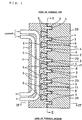
- Figs. 1 to 5 show structural members of a furnace body according to an embodiment in accordance with the present invention.
- Fig. 1 is a longitudinal sectional view thereof.
- Fig. 2 is a cross-sectional view taken along line II-II of Fig. 1.
- Fig. 3 is an enlarged fragmentary longitudinal sectional view of a supporting member for connecting and a rear brick.
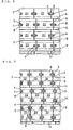
- Fig. 4 is a cross-sectional view taken along line IV-IV of Fig. 1.
- Fig. 5 is an isometric view of a refractory brick which makes up inner furnace refractories.
- reference numeral 1 denotes a metallic structural member having flow paths for a coolant within itself.
- Reference numeral 2 denotes inner furnace refractories (front bricks) provided on a cooling surface x of the metallic structural member 1.
- Reference numeral 3 denotes a supporting member for connecting which is protrudingly provided at a plurality of areas on the cooling surface x of the metallic structural member 1, and which supports an inner furnace refractories 2 by being inserted into a groove 8 which is provided on a rear surface side of the inner furnace refractories.
- Reference numeral 4 denotes a heat insulating member which is inserted between the supporting member for connecting 3 and the inner surface of the groove 8.
- Reference numeral 5 denotes a heat insulating buffer member which is inserted between the cooling surface x of the metallic structural member and the rear surface of the inner furnace refractories 2.
- the metallic structural member 1 comprises cooling tubes 6 which are flow paths for a coolant, and a cast metal portion 7 which is cast around the cooling tubes 6.
- the cooling tubes 6 are made of hollow steel tubes
- the cast metal portion 7 is made of cast iron.
- the inner furnace refractories 2 are provided on the cooling surface x of the metallic structural member 1 by being intercalated with the heat insulating buffer member 5.
- the inner furnace refractories 2 are made of a plurality of refractory bricks 20 which are arranged vertically and horizontally on the cooling surface x of the metallic structural member 1.
- a compressible heat insulating member 11 is inserted between the adjacent refractory bricks 20 to absorb thermal expansion.
- the heat insulating member 11 is made of glass-wool, rock wool, or the like.
- Each refractory brick 20 has a plurality of grooves 8 on the rear surface side thereof for inserting the supporting members for connecting 3 which are protrudingly provided on the cooling surface x of the metallic structural member 1.
- the refractory brick 20 according to this embodiment has two grooves 8 at an upper and a lower region of both side portions on the rear surface side thereof, as shown in Figs. 2 and 5.
- the depth of this groove 8 is not equal to the entire thickness of the refractory brick 20, and the groove 8 is formed so as to have a proper depth being provided from the rear surface side (the depth is about 10 to 50 % of the entire thickness of the brick).
- the groove 8 is preferably formed in such a manner that a length a of the groove 8 in the width direction of the refractory brick and a distance L between the groove 8 and the upper end surface of the refractory brick satisfy the relationship L > a (when two grooves 8 are provided at an upper and a lower region of the rear surface side of the refractory brick according to the present embodiment, the upper groove 8 preferably satisfies the above-mentioned relationship).
- the lower groove 8 is preferably formed in such a manner that a length a ' of the groove 8 in the width direction of the refractory brick and a distance L ' between the groove 8 and the lower surface of the refractory brick satisfy the relationship L ' > a '.
- the refractory brick 20 is preferably made of an SiC based refractory brick (for example, SiC : 70 to 100 wt%, SiO 2 : 0 to 30 wt%) or the like from the stand point of durability.
- SiC based refractory brick for example, SiC : 70 to 100 wt%, SiO 2 : 0 to 30 wt%) or the like from the stand point of durability.
- a rear brick 9 is protrudingly provided between the adjacent supporting members for connecting 3 at a rear surface of the inner furnace refractories 2 and is fixed to the inner furnace refractories using mortar 10 as shown in Fig. 3, in order to prevent a steep thermal gradient from occurring in the inner furnace refractories 2 (front brick) and to obtain a certain insulating effect even if the inner furnace refractories 2 fall off.
- a cross-sectional view of this rear brick 9 is an approximate trapezium and the raised bottom thereof is fixed to the rear surface of the inner furnace refractories.
- a cooling surface x of the metallic structural member 1 is formed along the concavo-convex rear surface the inner furnace refractories 2 including an outer surface of the rear brick 9.
- the heat insulating buffer member 5 is provided for absorbing thermal shock to the refractory brick 20 at casting of the cast metal portion 7, and is inserted between the rear surface the inner furnace refractories 2 including the outer surface of the rear brick 9 and the cooling surface x of the metallic structural member 1.
- This heat insulating buffer member 5 is made of glass wool, rock wool, or the like.
- the supporting member for connecting 3 is protrudingly provided on the cooling surface x of the metallic structural member 1 by fixing one end of a cylindrical bar to the cast metal portion 7 which is used to construct the metallic structural member 1 (the fixation is performed by casting one end of the cylindrical bar into the cast metal portion 7 when the cast metal portion 7 is cast), and inserted into the groove 8 in the inner furnace refractories 2 so as to support the inner furnace refractories 2 to the metallic structural member 1.
- a length of the supporting member for connecting 3 (a protruding length from the cooling surface x ) is determined at 10 to 50% the thickness of the refractory brick 20.
- this supporting member for connecting 3 is constructed of a cylindrical bar according to the present embodiment, the strength of the supporting member for connecting itself is most easily ensured. And then, this construction is most preferable with respect to the strength of the refractory brick because of the possibility of making the size of the groove 8 small.
- the construction is not limited thereto, and the supporting member for connecting 3 may be constructed of a plate as described below in another embodiment.
- the supporting member for connecting 3 is preferably made of a metal having high heat resistance and high strength at a high temperature.
- a material thereof is not particularly limited, in particular, the material preferably includes a stainless steel such as SUS-310S, a heat resistant steel such as SS-400 and HA-230, or the like.
- the supporting member for connecting 3 preferably has enough tensile strength and enough bending strength for supporting the refractories at a high temperature of 300 to 400 °C.
- the heat insulating member 4 is inserted between the supporting member for connecting 3 and the inner surface of the groove 8 for maximally suppressing thermal conductivity between thereof.
- Rock wool, glass wool, or the like can be used as the heat insulating member 4.
- the heat insulating member 4 is filled or inserted between the supporting member for connecting 3 and the groove 8 by being wound around or by being attached with a laminated form to the outer side of the supporting member for connecting 3, by being inserted into the groove 8 with the supporting member for connecting 3 with this state, and by being filled with a heat insulating material into a gap within the groove as the need arises.
- the heat insulating member 4 has a function for ensuring a clearance (usually 1 to 5 mm at room temperature) between the supporting member for connecting 3 and the groove 8 to absorb thermal expansion of the metallic supporting member for connecting 3.
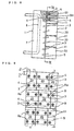
- Figs. 6 and 7 are cross-sectional views of other embodiments of a supported construction of inner furnace refractories 2 by a supporting member for connecting 3 in the same way as Fig. 2.
- a height of each refractory brick 20 which makes up the inner furnace refractories 2 is made to be small, a groove 8 is provided at each one area of both side portions of the rear surface side of the refractory brick 20, and the supporting member for connecting 3 is inserted into the groove 8.
- a groove 8 is provided at a similar position as that in Fig. 2, and a supporting member for connecting 3 is constructed of a plate member, so that both end portions of the supporting member for connecting 3 having a plate shape are inserted into both grooves 8 of the adjacent refractory bricks 20 in the width direction of a structural member of a furnace body.
- a supporting member for connecting 3 and a supported configuration of inner furnace refractories 2 thereby may have a variety of configurations other than the above-described embodiments.
- the groove for mounting 8 is provided on the rear surface side of the refractory brick 20 for supporting the inner furnace refractories 2 by the supporting member for connecting 3, a hole for mounting may be provided instead of the groove 8.
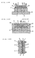
- Figs. 8 to 10 show an embodiment in which a hole for mounting 8a is formed on a rear surface of a refractory brick 20 for inserting a supporting member for connecting 3.
- Fig. 8 is a partially cut off side view
- Fig. 9 is a cross-sectional view taken along line IX-IX of Fig. 8
- Fig. 10 is an enlarged fragmentary longitudinal sectional view of a supporting member for connecting 3.
- each refractory brick 20 which makes up inner furnace refractories 2 has a plurality of holes for mounting 8a for inserting of the supporting member for connecting 3 on the rear surface side of the refractory brick.
- These holes for mounting 8a are formed at four areas, that is, upper, lower, right and left areas of each refractory brick 20, as shown in Fig. 9.
- the holes for mounting 8a are preferably formed in such a manner that a distance a '' between the inner end surface of the hole for mounting 8a within the refractory brick and the side end surface of the refractory brick and a distance L " between the upper end surface of the holes for mounting 8a and the upper end surface of the refractory brick satisfy the relationship L '' > a '' (when the holes for mounting 8a are provided at an upper and a lower region of the rear surface side of the refractory brick, the upper hole for mounting 8a is preferably formed so as to satisfy the above-described relationship).
- the supporting member for connecting 3 which is protrudingly provided on a cooling surface x of a metallic structural member 1 is made of a metallic cylindrical bar.
- the inner furnace refractories 2 are supported to the metallic structural member 1 by inserting the supporting member for connecting 3 into the hole for mounting 8a through the heat insulating member 4.
- the supporting member for connecting 3 is upwardly inclined having an inclination angle ⁇ 1 or ⁇ 2 for preventing the refractory brick 20 from falling off from the supporting member for connecting 3, as shown in Fig. 10, and the inclination angles ⁇ 1 and ⁇ 2 of above and below supporting members for connecting 3 are different from each other. Since adjacent supporting members for connecting 3 above and below have a different inclination angle ⁇ 1 or ⁇ 2 , the refractory brick 20 hardly falls off from the supporting member for connecting 3.
- the inclination angle is optionally selected from a range of 5 to 25°.
- a rear brick 9 is also provided on a rear surface side of inner furnace refractories 2 with respect to the present embodiment in the same way as the embodiments shown in Figs. 1 to 5.
- a metallic structural member 1 which is used to construct a structural member of a furnace in accordance with the present invention preferably has a configuration in which a cast metal portion 7 is cast around a cooling tube 6 while taking into consideration ease of manufacturing, integrity in the construction, and the like as the above-described embodiments.
- other configurations may be employed in such a manner that a body of a metallic structural member is manufactured by casting, rolling or the like, and a cooling tube is attached to the metallic structural member or a flow path for a coolant is formed by a boring process or the like.
- an optional metal material such as Cu or Cu alloys other than cast steel can be employed as a material of the metallic structural member 1.
- the above-described structural member of a furnace body in accordance with the present invention is used for constructing a wall and a bottom of a vertical metallurgical furnace such as a blast furnace, a scrap smelting furnace, or the like.
- a vertical metallurgical furnace such as a blast furnace, a scrap smelting furnace, or the like.
- the structural member of a furnace body is usually cumulated in the inside of the furnace body shell, and the furnace wall is constructed by fixing the metallic structural member 1 to the furnace body shell.
- inner furnace refractories 2 are properly cooled by a cooling surface x of a metallic structural member 1 having a cooling tube 6.
- a supporting member for connecting 3 which supports the inner furnace refractories 2 is made of a metal such as stainless steel or the like, so that breakage hardly occurs.
- a supporting member for connecting 3 is made of metal and a heat insulating member 4 is also inserted between the supporting member for connecting 3 and a groove for mounting 8 or a hole for mounting 8a, cooling of the inside of the inner furnace refractories is properly suppressed.
- each refractory brick 20 which will make up inner furnace refractories 2 is arranged on a flat base 12 in such a manner that a groove for mounting 8 faces upward.
- a heat insulating member 11 is inserted between adjacent refractory bricks 20.
- a metallic cylindrical bar 30 which will be used to construct a supporting member for connecting 3 is inserted into each groove 8.
- a heat insulating material is wound around the outer side of the cylindrical bar 30 and the metallic cylindrical bar 30 is inserted into the groove 8, being attached with the heat insulating material, so that a heat insulating member 4 (not shown) is inserted between the supporting member for connecting 3 and the inner surface of the groove 8.
- a rear brick 9 is attached between the adjacent cylindrical bars 30 on the upper surface (rear surface) of the refractory brick 20 using mortar 10.
- a heat insulating buffer member 5 is fixed on the upper surface (rear surface) of the refractory brick 20 including the rear brick 9.
- a cooling tube 6 which will be used to construct a part of a metallic structural member 1 is provided above the refractory brick 20 using a proper holding means.
- the inner furnace refractories 2 and the cooling tubes 6 which are provided above the inner furnace refractories 2 are covered with a mold 13.
- a space inside the mold 13 including the cooling tubes 6 is cast.
- a metallic structural member 1 in which a cast metal portion 7 is cast around the cooling tubes 6 is formed.
- each cylindrical bar 30 is integrated with the cast metal portion 7, and a supporting member for connecting 3 which is protrudingly provided on a cooling surface x of the metallic structural member 1 is formed.
- thermal shock to the refractory brick 20 due to pouring is absorbed by the heat insulating buffer member 5.
- the mold 13 is taken off, so that a structural member of a furnace body in which the metallic structural member 1 is connected with the inner furnace refractories 2 through the supporting member for connecting 3 is obtained.
- inner furnace refractories are properly cooled and effectively prevented from deterioration.
- the inner furnace refractories are effectively prevented from falling off due to damage to the inner furnace refractories and breakage of a supporting member for connecting, so that the service life of a metallurgical shaft furnace such as a blast furnace can be prolonged to a large extent.
Landscapes
- Engineering & Computer Science (AREA)
- Chemical & Material Sciences (AREA)
- Mechanical Engineering (AREA)
- General Engineering & Computer Science (AREA)
- Manufacturing & Machinery (AREA)
- Materials Engineering (AREA)
- Metallurgy (AREA)
- Organic Chemistry (AREA)
- Furnace Housings, Linings, Walls, And Ceilings (AREA)
- Blast Furnaces (AREA)
Claims (7)
- Bauteil eines Ofengestells für einen metallurgischen Schaftofen, wobei vorgesehen sind:gekennzeichnet durchein metallisches Bauteil (1), in welchem ein Flussweg für Kühlmittel vorgesehen ist;innere Ofenfeuerfeststeine (2), die auf einer Kühloberfläche (x) des metallischen Bauteils (1) angeordnet sind;metallische Halteteile (3) zum Verbinden, welche die inneren Ofenfeuerfeststeine (2) dadurch haltern, dass sie vorspringend auf der Kühloberfläche (x) des metallischen Bauteils (1) vorgesehen sind, und in Montagenuten (8) oder Montagelöcher (8a) eingeführt sind, die an der Seite einer hinteren Oberfläche der inneren Ofenfeuerfeststeine (2) vorgesehen sind; undWärmeisolierteile (4), die zwischen die Halteteile (3) und innere Oberflächen der Nuten (8) oder der Löcher (8a) eingeführt sind;
hintere Steine (9), die vorspringend zwischen benachbarten Halteteilen (3) zum Verbinden einer hinteren Oberfläche der inneren Ofenfeuerfeststeine (2) vorgesehen sind, um das Auftreten eines steilen Wärmegradienten in den inneren Ofenfeuerfeststeinen (2) zu verhindern, und eine Isolierwirkung selbst dann zu erzielen, wenn die inneren Ofenfeuerfeststeine herunterfallen. - Bauteil nach Anspruch 1, bei welchem das metallische Bauteil (1) ein Kühlrohr (6) aufweist, welches den Flussweg für das Kühlmittel bildet, sowie einen gegossenen Metallabschnitt (7), der um das Kühlrohr (6) herumgegossen ist.
- Bauteil nach Anspruch 1, welches weiterhin ein wärmeisolierendes Pufferteil (5) aufweist, das zwischen die Kühloberfläche (x) des metallischen Bauteils (1) und die hintere Oberfläche der inneren Ofenfeuerfeststeine (2) eingeführt ist.
- Bauteil nach Anspruch 1, bei welchem
die inneren Ofenfeuerfeststeine (2) mehrere Feuerfeststeine (20) umfassen; und
die Montagenuten (8) an beiden Seitenabschnitten der Seite einer hinteren Oberfläche jedes Feuerfeststeins (20) vorgesehen sind, um die Halteteile (3) einzuführen. - Bauteil nach Anspruch 4, bei welchem
die Montagenut (8) eine Länge "a" in Richtung der Breite des Feuerfeststeins (20) und eine Entfernung "L" zwischen der Nut (8) und einer oberen Endoberfläche des Feuerfeststeins (20) aufweist; und
die Länge "a" und die Entfernung "L" der Bedingung L > a genügen. - Bauteil nach Anspruch 1, bei welchem das Halteteil (3) eine metallische, zylindrische Stange (30) aufweist.
- Bauteil nach Anspruch 4, welches weiterhin Wärmeisolierteile (11) aufweist, die zwischen benachbarten Feuerfeststeinen (20) angeordnet sind.
Applications Claiming Priority (2)
| Application Number | Priority Date | Filing Date | Title |
|---|---|---|---|
| JP36842897 | 1997-12-26 | ||
| JP36842897A JP3397113B2 (ja) | 1997-12-26 | 1997-12-26 | 竪型冶金炉用の炉体構造部材 |
Publications (2)
| Publication Number | Publication Date |
|---|---|
| EP0926247A1 EP0926247A1 (de) | 1999-06-30 |
| EP0926247B1 true EP0926247B1 (de) | 2004-03-03 |
Family
ID=18491795
Family Applications (1)
| Application Number | Title | Priority Date | Filing Date |
|---|---|---|---|
| EP98124424A Expired - Lifetime EP0926247B1 (de) | 1997-12-26 | 1998-12-22 | Kühlplatte für metallurgische Schachtöfen |
Country Status (8)
| Country | Link |
|---|---|
| US (1) | US6258315B1 (de) |
| EP (1) | EP0926247B1 (de) |
| JP (1) | JP3397113B2 (de) |
| KR (1) | KR100288055B1 (de) |
| AU (1) | AU730381B2 (de) |
| BR (1) | BR9805689A (de) |
| DE (1) | DE69822107T2 (de) |
| TW (1) | TW393562B (de) |
Families Citing this family (13)
| Publication number | Priority date | Publication date | Assignee | Title |
|---|---|---|---|---|
| JP2000248305A (ja) * | 1999-02-26 | 2000-09-12 | Nippon Steel Corp | ステーブクーラー |
| FI109937B (fi) * | 1999-05-26 | 2002-10-31 | Outokumpu Oy | Menetelmä metallurgisen reaktorin sulatilan komposiitti-jäähdytyselementin valmistamiseksi ja menetelmällä valmistettu komposiittijäähdytyselementti |
| US6796362B2 (en) * | 2000-06-01 | 2004-09-28 | Brunswick Corporation | Apparatus for producing a metallic slurry material for use in semi-solid forming of shaped parts |
| DE10061359C2 (de) * | 2000-12-09 | 2003-01-02 | Didier M & P Energietechnik Gm | Kühleinrichtung für Schachtöfen |
| JP4064387B2 (ja) * | 2004-09-03 | 2008-03-19 | 日鉱金属株式会社 | 炉体水冷ジャケット |
| JP5442196B2 (ja) * | 2007-11-29 | 2014-03-12 | 新日鉄住金エンジニアリング株式会社 | 廃棄物ガス化溶融炉の炉体冷却装置および炉体冷却方法 |
| DE102008008477A1 (de) * | 2008-02-08 | 2009-08-13 | Sms Demag Ag | Kühlelement zur Kühlung der feuerfesten Auskleidung eines metallurgischen Ofens (AC,DC) |
| KR20120017439A (ko) * | 2009-05-06 | 2012-02-28 | 루바타 에스푸 오와이 | 건식야금 반응기를 위한 냉각 요소를 제조하는 방법 및 그 냉각 요소 |
| US20120266826A1 (en) * | 2011-04-22 | 2012-10-25 | Saint-Gobain Ceramics & Plastics, Inc. | System, method and apparatus for thermally conductive refractory tiles for waste to energy boiler walls |
| LU92472B1 (en) | 2014-06-06 | 2015-12-07 | Wurth Paul Sa | Heat protection assembly for a charging installation of a metallurgical reactor |
| JP7214814B2 (ja) * | 2016-12-30 | 2023-01-30 | アルセロールミタル | 溶鉱炉のための、耐摩耗性インサートを有する銅の冷却プレート |
| EP3562963B1 (de) * | 2016-12-30 | 2021-11-17 | Arcelormittal | Kupferkühlplatte mit verschleissbeständigen einsätzen für einen hochofen |
| CN113390266A (zh) * | 2021-04-02 | 2021-09-14 | 山东墨龙石油机械股份有限公司 | 一种用于熔融还原炉过渡区的冷却装置 |
Family Cites Families (9)
| Publication number | Priority date | Publication date | Assignee | Title |
|---|---|---|---|---|
| DE2719165C2 (de) * | 1977-04-29 | 1983-02-03 | Thyssen AG vorm. August Thyssen-Hütte, 4100 Duisburg | Kühlelement für einen metallurgischen Ofen |
| JPS5579986A (en) | 1978-12-12 | 1980-06-16 | Nippon Steel Corp | Stave for metallurgical furnace |
| SU949003A1 (ru) * | 1981-01-21 | 1982-08-07 | Днепропетровский Ордена Трудового Красного Знамени Металлургический Институт | Плитовый холодильник доменной печи |
| JPS60140089A (ja) * | 1983-12-27 | 1985-07-24 | 住友金属工業株式会社 | 炉壁構造 |
| FR2592145B1 (fr) | 1985-12-23 | 1989-08-18 | Cometherm Sa Cie Expl Thermiqu | Procede de realisation de parois refractaires de protection de fours ou chambres de combustion et brique refractaire pour la mise en oeuvre dudit procede. |
| JPH02163307A (ja) * | 1988-05-25 | 1990-06-22 | Nippon Steel Corp | ステイーブクーラの煉瓦鋳込み方法 |
| JPH06158130A (ja) * | 1992-11-27 | 1994-06-07 | Nippon Steel Corp | ステーブクーラー |
| JP2765449B2 (ja) | 1993-09-20 | 1998-06-18 | 日本鋼管株式会社 | 高炉炉体冷却装置 |
| JP2932985B2 (ja) * | 1995-11-13 | 1999-08-09 | 住友金属工業株式会社 | ステーブクーラ |
-
1997
- 1997-12-26 JP JP36842897A patent/JP3397113B2/ja not_active Expired - Fee Related
-
1998
- 1998-12-21 US US09/217,562 patent/US6258315B1/en not_active Expired - Fee Related
- 1998-12-22 DE DE69822107T patent/DE69822107T2/de not_active Expired - Fee Related
- 1998-12-22 EP EP98124424A patent/EP0926247B1/de not_active Expired - Lifetime
- 1998-12-23 KR KR1019980057680A patent/KR100288055B1/ko not_active Expired - Fee Related
- 1998-12-23 AU AU98164/98A patent/AU730381B2/en not_active Ceased
- 1998-12-24 TW TW087121603A patent/TW393562B/zh not_active IP Right Cessation
- 1998-12-24 BR BR9805689-1A patent/BR9805689A/pt not_active IP Right Cessation
Also Published As
| Publication number | Publication date |
|---|---|
| EP0926247A1 (de) | 1999-06-30 |
| DE69822107T2 (de) | 2005-01-20 |
| DE69822107D1 (de) | 2004-04-08 |
| JPH11193407A (ja) | 1999-07-21 |
| AU730381B2 (en) | 2001-03-08 |
| BR9805689A (pt) | 2000-01-04 |
| KR19990063380A (ko) | 1999-07-26 |
| TW393562B (en) | 2000-06-11 |
| KR100288055B1 (ko) | 2002-09-19 |
| US6258315B1 (en) | 2001-07-10 |
| JP3397113B2 (ja) | 2003-04-14 |
| AU9816498A (en) | 1999-07-15 |
Similar Documents
| Publication | Publication Date | Title |
|---|---|---|
| EP0926247B1 (de) | Kühlplatte für metallurgische Schachtöfen | |
| AU713079B2 (en) | Cooling plate for use in shaft furnaces | |
| MX2011010820A (es) | Placa de enfriamiento para un horno metalurgico. | |
| KR101270919B1 (ko) | 냉각 요소 | |
| US3984089A (en) | Cooled refractory lined shaft furnace and stave-cooler to be used therefore | |
| JP2003183712A (ja) | 竪型冶金炉用の炉体構造部材 | |
| JP6162982B2 (ja) | スキッドボタン | |
| JP2000256716A (ja) | 炉体の耐火物保持構造 | |
| JP2765449B2 (ja) | 高炉炉体冷却装置 | |
| AU754513B2 (en) | Pouring tube | |
| JPH11335711A (ja) | 竪型冶金炉用のステーブの製造方法 | |
| JP2000256715A (ja) | 炉の耐火物保持構造 | |
| JP2000297308A (ja) | ステーブクーラー | |
| JP7843624B2 (ja) | 取鍋 | |
| KR102759774B1 (ko) | 열 변형을 개선한 턴디쉬 커버 | |
| JP7610117B2 (ja) | タンディッシュ | |
| JP3267908B2 (ja) | 連続鋳造用ロングノズル | |
| JP2778339B2 (ja) | 熱応力緩和型傾斜機能材料を備えたステーブクーラ | |
| JP4026528B2 (ja) | ステーブクーラ | |
| JP4088007B2 (ja) | 真空脱ガス装置用浸漬管 | |
| JPH08120313A (ja) | ステーブ | |
| JP2000026910A (ja) | 高炉炉体 | |
| JPH0343219Y2 (de) | ||
| JP2001123209A (ja) | ステーブクーラー | |
| JPH01127610A (ja) | ステーブクーラー及びステーブクーラーの煉瓦鋳ぐるみ方法 |
Legal Events
| Date | Code | Title | Description |
|---|---|---|---|
| PUAI | Public reference made under article 153(3) epc to a published international application that has entered the european phase |
Free format text: ORIGINAL CODE: 0009012 |
|
| 17P | Request for examination filed |
Effective date: 19981222 |
|
| AK | Designated contracting states |
Kind code of ref document: A1 Designated state(s): DE GB |
|
| AX | Request for extension of the european patent |
Free format text: AL;LT;LV;MK;RO;SI |
|
| AKX | Designation fees paid |
Free format text: DE GB |
|
| 17Q | First examination report despatched |
Effective date: 20010330 |
|
| GRAP | Despatch of communication of intention to grant a patent |
Free format text: ORIGINAL CODE: EPIDOSNIGR1 |
|
| GRAS | Grant fee paid |
Free format text: ORIGINAL CODE: EPIDOSNIGR3 |
|
| GRAA | (expected) grant |
Free format text: ORIGINAL CODE: 0009210 |
|
| AK | Designated contracting states |
Kind code of ref document: B1 Designated state(s): DE GB |
|
| REG | Reference to a national code |
Ref country code: GB Ref legal event code: FG4D |
|
| REF | Corresponds to: |
Ref document number: 69822107 Country of ref document: DE Date of ref document: 20040408 Kind code of ref document: P |
|
| PLBE | No opposition filed within time limit |
Free format text: ORIGINAL CODE: 0009261 |
|
| STAA | Information on the status of an ep patent application or granted ep patent |
Free format text: STATUS: NO OPPOSITION FILED WITHIN TIME LIMIT |
|
| 26N | No opposition filed |
Effective date: 20041206 |
|
| PGFP | Annual fee paid to national office [announced via postgrant information from national office to epo] |
Ref country code: DE Payment date: 20051215 Year of fee payment: 8 |
|
| PGFP | Annual fee paid to national office [announced via postgrant information from national office to epo] |
Ref country code: GB Payment date: 20051221 Year of fee payment: 8 |
|
| PG25 | Lapsed in a contracting state [announced via postgrant information from national office to epo] |
Ref country code: DE Free format text: LAPSE BECAUSE OF NON-PAYMENT OF DUE FEES Effective date: 20070703 |
|
| GBPC | Gb: european patent ceased through non-payment of renewal fee |
Effective date: 20061222 |
|
| PG25 | Lapsed in a contracting state [announced via postgrant information from national office to epo] |
Ref country code: GB Free format text: LAPSE BECAUSE OF NON-PAYMENT OF DUE FEES Effective date: 20061222 |