EP0926340A2 - Revêtement du palier d'un plateau en biais - Google Patents
Revêtement du palier d'un plateau en biais Download PDFInfo
- Publication number
- EP0926340A2 EP0926340A2 EP98124481A EP98124481A EP0926340A2 EP 0926340 A2 EP0926340 A2 EP 0926340A2 EP 98124481 A EP98124481 A EP 98124481A EP 98124481 A EP98124481 A EP 98124481A EP 0926340 A2 EP0926340 A2 EP 0926340A2
- Authority
- EP
- European Patent Office
- Prior art keywords
- swash plate
- plate
- swash
- layer
- solid lubricant
- Prior art date
- Legal status (The legal status is an assumption and is not a legal conclusion. Google has not performed a legal analysis and makes no representation as to the accuracy of the status listed.)
- Granted
Links
- 238000000576 coating method Methods 0.000 title claims abstract description 31
- 239000011248 coating agent Substances 0.000 title claims abstract description 26
- 239000000314 lubricant Substances 0.000 claims abstract description 97
- 239000000463 material Substances 0.000 claims abstract description 96
- 239000007787 solid Substances 0.000 claims abstract description 95
- 239000003507 refrigerant Substances 0.000 claims abstract description 70
- 230000002093 peripheral effect Effects 0.000 claims abstract description 37
- CWQXQMHSOZUFJS-UHFFFAOYSA-N molybdenum disulfide Chemical compound S=[Mo]=S CWQXQMHSOZUFJS-UHFFFAOYSA-N 0.000 claims abstract description 23
- 229910052982 molybdenum disulfide Inorganic materials 0.000 claims abstract description 23
- 238000000034 method Methods 0.000 claims description 42
- 230000008569 process Effects 0.000 claims description 26
- 229920005989 resin Polymers 0.000 claims description 20
- 239000011347 resin Substances 0.000 claims description 20
- 238000004381 surface treatment Methods 0.000 claims description 10
- 238000000227 grinding Methods 0.000 claims description 9
- ATJFFYVFTNAWJD-UHFFFAOYSA-N Tin Chemical compound [Sn] ATJFFYVFTNAWJD-UHFFFAOYSA-N 0.000 claims description 6
- 230000001050 lubricating effect Effects 0.000 claims description 4
- 238000007788 roughening Methods 0.000 claims description 4
- 229910052582 BN Inorganic materials 0.000 claims description 3
- PZNSFCLAULLKQX-UHFFFAOYSA-N Boron nitride Chemical compound N#B PZNSFCLAULLKQX-UHFFFAOYSA-N 0.000 claims description 3
- OKTJSMMVPCPJKN-UHFFFAOYSA-N Carbon Chemical compound [C] OKTJSMMVPCPJKN-UHFFFAOYSA-N 0.000 claims description 3
- 229910000410 antimony oxide Inorganic materials 0.000 claims description 3
- NBVXSUQYWXRMNV-UHFFFAOYSA-N fluoromethane Chemical compound FC NBVXSUQYWXRMNV-UHFFFAOYSA-N 0.000 claims description 3
- 229910002804 graphite Inorganic materials 0.000 claims description 3
- 239000010439 graphite Substances 0.000 claims description 3
- 229910052738 indium Inorganic materials 0.000 claims description 3
- APFVFJFRJDLVQX-UHFFFAOYSA-N indium atom Chemical compound [In] APFVFJFRJDLVQX-UHFFFAOYSA-N 0.000 claims description 3
- 229910000464 lead oxide Inorganic materials 0.000 claims description 3
- VTRUBDSFZJNXHI-UHFFFAOYSA-N oxoantimony Chemical compound [Sb]=O VTRUBDSFZJNXHI-UHFFFAOYSA-N 0.000 claims description 3
- YEXPOXQUZXUXJW-UHFFFAOYSA-N oxolead Chemical compound [Pb]=O YEXPOXQUZXUXJW-UHFFFAOYSA-N 0.000 claims description 3
- ITRNXVSDJBHYNJ-UHFFFAOYSA-N tungsten disulfide Chemical compound S=[W]=S ITRNXVSDJBHYNJ-UHFFFAOYSA-N 0.000 claims description 3
- 230000008859 change Effects 0.000 claims description 2
- 230000001747 exhibiting effect Effects 0.000 claims 1
- 239000010410 layer Substances 0.000 description 205
- 229910052751 metal Inorganic materials 0.000 description 28
- 239000002184 metal Substances 0.000 description 28
- 229910045601 alloy Inorganic materials 0.000 description 22
- 239000000956 alloy Substances 0.000 description 22
- 229920002312 polyamide-imide Polymers 0.000 description 19
- 238000005507 spraying Methods 0.000 description 15
- 239000011247 coating layer Substances 0.000 description 14
- 230000000052 comparative effect Effects 0.000 description 14
- 239000002245 particle Substances 0.000 description 14
- 230000006835 compression Effects 0.000 description 13
- 238000007906 compression Methods 0.000 description 13
- 238000010971 suitability test Methods 0.000 description 12
- 238000006243 chemical reaction Methods 0.000 description 9
- 230000007547 defect Effects 0.000 description 8
- 239000010687 lubricating oil Substances 0.000 description 8
- 238000012546 transfer Methods 0.000 description 8
- 238000005299 abrasion Methods 0.000 description 7
- 229910052961 molybdenite Inorganic materials 0.000 description 7
- MUBZPKHOEPUJKR-UHFFFAOYSA-N Oxalic acid Chemical compound OC(=O)C(O)=O MUBZPKHOEPUJKR-UHFFFAOYSA-N 0.000 description 6
- 238000004378 air conditioning Methods 0.000 description 6
- 238000004519 manufacturing process Methods 0.000 description 6
- 238000010276 construction Methods 0.000 description 5
- 238000001816 cooling Methods 0.000 description 5
- 239000010949 copper Substances 0.000 description 5
- 239000000843 powder Substances 0.000 description 5
- 239000002344 surface layer Substances 0.000 description 5
- XEEYBQQBJWHFJM-UHFFFAOYSA-N Iron Chemical compound [Fe] XEEYBQQBJWHFJM-UHFFFAOYSA-N 0.000 description 4
- QAOWNCQODCNURD-UHFFFAOYSA-N Sulfuric acid Chemical compound OS(O)(=O)=O QAOWNCQODCNURD-UHFFFAOYSA-N 0.000 description 4
- 229910052782 aluminium Inorganic materials 0.000 description 4
- XAGFODPZIPBFFR-UHFFFAOYSA-N aluminium Chemical compound [Al] XAGFODPZIPBFFR-UHFFFAOYSA-N 0.000 description 4
- 238000013459 approach Methods 0.000 description 4
- 238000005336 cracking Methods 0.000 description 4
- 230000007423 decrease Effects 0.000 description 4
- 230000007246 mechanism Effects 0.000 description 4
- 229920001343 polytetrafluoroethylene Polymers 0.000 description 4
- 239000004810 polytetrafluoroethylene Substances 0.000 description 4
- 229910000838 Al alloy Inorganic materials 0.000 description 3
- RYGMFSIKBFXOCR-UHFFFAOYSA-N Copper Chemical compound [Cu] RYGMFSIKBFXOCR-UHFFFAOYSA-N 0.000 description 3
- 238000007743 anodising Methods 0.000 description 3
- 229910052802 copper Inorganic materials 0.000 description 3
- 230000006872 improvement Effects 0.000 description 3
- 238000007747 plating Methods 0.000 description 3
- -1 polytetrafluoroethylene Polymers 0.000 description 3
- 229910000831 Steel Inorganic materials 0.000 description 2
- 230000008901 benefit Effects 0.000 description 2
- 238000007796 conventional method Methods 0.000 description 2
- 230000000694 effects Effects 0.000 description 2
- 229910052742 iron Inorganic materials 0.000 description 2
- 230000013011 mating Effects 0.000 description 2
- 238000005259 measurement Methods 0.000 description 2
- 238000002844 melting Methods 0.000 description 2
- 230000008018 melting Effects 0.000 description 2
- 239000003595 mist Substances 0.000 description 2
- 238000012986 modification Methods 0.000 description 2
- 230000004048 modification Effects 0.000 description 2
- 235000006408 oxalic acid Nutrition 0.000 description 2
- 238000005192 partition Methods 0.000 description 2
- 239000010959 steel Substances 0.000 description 2
- XLYOFNOQVPJJNP-UHFFFAOYSA-N water Substances O XLYOFNOQVPJJNP-UHFFFAOYSA-N 0.000 description 2
- 229910021364 Al-Si alloy Inorganic materials 0.000 description 1
- 229910018566 Al—Si—Mg Inorganic materials 0.000 description 1
- 229910017755 Cu-Sn Inorganic materials 0.000 description 1
- 229910017818 Cu—Mg Inorganic materials 0.000 description 1
- 229910017927 Cu—Sn Inorganic materials 0.000 description 1
- OAICVXFJPJFONN-UHFFFAOYSA-N Phosphorus Chemical compound [P] OAICVXFJPJFONN-UHFFFAOYSA-N 0.000 description 1
- BQCADISMDOOEFD-UHFFFAOYSA-N Silver Chemical compound [Ag] BQCADISMDOOEFD-UHFFFAOYSA-N 0.000 description 1
- 230000009471 action Effects 0.000 description 1
- 239000010953 base metal Substances 0.000 description 1
- 230000015572 biosynthetic process Effects 0.000 description 1
- KUNSUQLRTQLHQQ-UHFFFAOYSA-N copper tin Chemical compound [Cu].[Sn] KUNSUQLRTQLHQQ-UHFFFAOYSA-N 0.000 description 1
- 230000001419 dependent effect Effects 0.000 description 1
- 238000011161 development Methods 0.000 description 1
- 229910003460 diamond Inorganic materials 0.000 description 1
- 239000010432 diamond Substances 0.000 description 1
- 238000006073 displacement reaction Methods 0.000 description 1
- 230000002708 enhancing effect Effects 0.000 description 1
- 238000000605 extraction Methods 0.000 description 1
- 230000005484 gravity Effects 0.000 description 1
- 229910003480 inorganic solid Inorganic materials 0.000 description 1
- 229910000765 intermetallic Inorganic materials 0.000 description 1
- 238000005461 lubrication Methods 0.000 description 1
- 238000003754 machining Methods 0.000 description 1
- 230000003647 oxidation Effects 0.000 description 1
- 238000007254 oxidation reaction Methods 0.000 description 1
- 229910052698 phosphorus Inorganic materials 0.000 description 1
- 239000011574 phosphorus Substances 0.000 description 1
- 239000011241 protective layer Substances 0.000 description 1
- 238000005057 refrigeration Methods 0.000 description 1
- 230000004044 response Effects 0.000 description 1
- 230000000717 retained effect Effects 0.000 description 1
- 238000005488 sandblasting Methods 0.000 description 1
- 229910052709 silver Inorganic materials 0.000 description 1
- 239000004332 silver Substances 0.000 description 1
- 238000005728 strengthening Methods 0.000 description 1
- 230000003746 surface roughness Effects 0.000 description 1
- 238000012360 testing method Methods 0.000 description 1
- 229920006337 unsaturated polyester resin Polymers 0.000 description 1
Images

Classifications
-
- F—MECHANICAL ENGINEERING; LIGHTING; HEATING; WEAPONS; BLASTING
- F04—POSITIVE - DISPLACEMENT MACHINES FOR LIQUIDS; PUMPS FOR LIQUIDS OR ELASTIC FLUIDS
- F04B—POSITIVE-DISPLACEMENT MACHINES FOR LIQUIDS; PUMPS
- F04B27/00—Multi-cylinder pumps specially adapted for elastic fluids and characterised by number or arrangement of cylinders
- F04B27/08—Multi-cylinder pumps specially adapted for elastic fluids and characterised by number or arrangement of cylinders having cylinders coaxial with, or parallel or inclined to, main shaft axis
- F04B27/10—Multi-cylinder pumps specially adapted for elastic fluids and characterised by number or arrangement of cylinders having cylinders coaxial with, or parallel or inclined to, main shaft axis having stationary cylinders
- F04B27/1036—Component parts, details, e.g. sealings, lubrication
- F04B27/1054—Actuating elements
-
- F—MECHANICAL ENGINEERING; LIGHTING; HEATING; WEAPONS; BLASTING
- F05—INDEXING SCHEMES RELATING TO ENGINES OR PUMPS IN VARIOUS SUBCLASSES OF CLASSES F01-F04
- F05C—INDEXING SCHEME RELATING TO MATERIALS, MATERIAL PROPERTIES OR MATERIAL CHARACTERISTICS FOR MACHINES, ENGINES OR PUMPS OTHER THAN NON-POSITIVE-DISPLACEMENT MACHINES OR ENGINES
- F05C2201/00—Metals
- F05C2201/04—Heavy metals
- F05C2201/0469—Other heavy metals
- F05C2201/0475—Copper or alloys thereof
-
- F—MECHANICAL ENGINEERING; LIGHTING; HEATING; WEAPONS; BLASTING
- F05—INDEXING SCHEMES RELATING TO ENGINES OR PUMPS IN VARIOUS SUBCLASSES OF CLASSES F01-F04
- F05C—INDEXING SCHEME RELATING TO MATERIALS, MATERIAL PROPERTIES OR MATERIAL CHARACTERISTICS FOR MACHINES, ENGINES OR PUMPS OTHER THAN NON-POSITIVE-DISPLACEMENT MACHINES OR ENGINES
- F05C2201/00—Metals
- F05C2201/04—Heavy metals
- F05C2201/0469—Other heavy metals
- F05C2201/049—Lead
-
- F—MECHANICAL ENGINEERING; LIGHTING; HEATING; WEAPONS; BLASTING
- F05—INDEXING SCHEMES RELATING TO ENGINES OR PUMPS IN VARIOUS SUBCLASSES OF CLASSES F01-F04
- F05C—INDEXING SCHEME RELATING TO MATERIALS, MATERIAL PROPERTIES OR MATERIAL CHARACTERISTICS FOR MACHINES, ENGINES OR PUMPS OTHER THAN NON-POSITIVE-DISPLACEMENT MACHINES OR ENGINES
- F05C2201/00—Metals
- F05C2201/04—Heavy metals
- F05C2201/0469—Other heavy metals
- F05C2201/0493—Tin
-
- F—MECHANICAL ENGINEERING; LIGHTING; HEATING; WEAPONS; BLASTING
- F05—INDEXING SCHEMES RELATING TO ENGINES OR PUMPS IN VARIOUS SUBCLASSES OF CLASSES F01-F04
- F05C—INDEXING SCHEME RELATING TO MATERIALS, MATERIAL PROPERTIES OR MATERIAL CHARACTERISTICS FOR MACHINES, ENGINES OR PUMPS OTHER THAN NON-POSITIVE-DISPLACEMENT MACHINES OR ENGINES
- F05C2203/00—Non-metallic inorganic materials
- F05C2203/08—Ceramics; Oxides
- F05C2203/0804—Non-oxide ceramics
- F05C2203/0856—Sulfides
- F05C2203/086—Sulfides of molybdenum
-
- F—MECHANICAL ENGINEERING; LIGHTING; HEATING; WEAPONS; BLASTING
- F05—INDEXING SCHEMES RELATING TO ENGINES OR PUMPS IN VARIOUS SUBCLASSES OF CLASSES F01-F04
- F05C—INDEXING SCHEME RELATING TO MATERIALS, MATERIAL PROPERTIES OR MATERIAL CHARACTERISTICS FOR MACHINES, ENGINES OR PUMPS OTHER THAN NON-POSITIVE-DISPLACEMENT MACHINES OR ENGINES
- F05C2253/00—Other material characteristics; Treatment of material
- F05C2253/12—Coating
Definitions
- the present invention relates to a single-headed piston type refrigerant compressor of the type in which rotation of a swash plate is converted into a reciprocation of a plurality of single-headed pistons via a plurality of pairs of shoes arranged between an outer periphery of the swash plate and the single-headed pistons.
- the present invention also relates to a method of producing a swash plate suitable for being incorporated in the above-mentioned type of single-headed piston type refrigerant compressor.
- a swash-plate-operated refrigerant compressor either a double-headed piston type refrigerant compressor or a single-headed piston type refrigerant compressor, has a housing assembly including a cylinder block provided with a plurality of cylinder bores formed therein, a plurality of pistons respectively slidably fitted in the cylinder bores, a drive shaft supported by the housing assembly to be rotatable about an axis of rotation, and a swash plate fixedly mounted on the drive shaft within a crank chamber at a constant inclination with respect to a plane perpendicular to the axis of rotation of the drive shaft or mounted on the drive shaft so that its inclination can be adjustably changed in the crank chamber.
- each piston i.e., a substantially middle part if the piston is of a double-headed type or an end part opposite the compressing end surface if the piston is of a single-headed type, is connected to a peripheral part of the swash plate via a pair of shoes to provide an operative engagement between each piston and the swash plate.
- This operative engagement of each piston and the swash plate permits the conversion of rotating motion of the drive shaft and the swash plate into a reciprocating motion of each piston.
- a refrigerant gas entraining a lubricating oil mist is circulated through the swash plate compressor to lubricate movable components of the compressor.
- the refrigerant gas washes off the lubricating oil remaining on the sliding surfaces of the swash plate before the lubricating oil mist reaches the swash plate and hence the surfaces of the swash plate are in a dried-surface condition having no lubricating oil, and therefore the swash plate and the shoes must unavoidably start to slide relative to each other without lubrication.
- the swash plate must be exposed to a very severe operating condition during the initial stage of sliding motion thereof.
- a new refrigerant such as R134a, which has recently become used instead of the conventional refrigerant for the protection of the ozonosphere is more effective in creating a dried-surface condition than the conventional refrigerant. Accordingly, demand for an improvement in the lubricating property of the surfaces of the swash plate has progressively increased.
- the typical conventional method disclosed in Japanese Unexamined Patent Publication (Kokai) No. 8-199327 includes forming of a sprayed metal coating of a copper-base or aluminum-base material on a swash plate made of a base metal, and forming of a plated coating of lead-base material or a film of a polytetrafluoroethylene over the sprayed metal coating.
- the plated film or the film of the polytetrafluoroethylene is formed over the surface of the sprayed metal coating in order to improve the antiseizing property of the sprayed metal coating and to prevent the sprayed metal coating from cracking.
- a special consideration is provided to determination of the amount of stroke of the pistons, in order to reduce a top clearance between each piston and a valve plate assembly when the piston is at its top dead center, i.e., the minimum volume of the cylinder bore during the compression stroke of the piston, to the smallest possible amount near zero.
- the determination of the amount of stroke of each piston largely depends on a production accuracy in the thickness of the swash plate with respect to a designed thickness.
- an object of the present invention is to provide a single-headed piston type swash-plate-operated refrigerant compressor in which sliding contact of a swash plate with shoes is improved so as to obtain a good antiseizing property, an enhanced abrasion resistance and a thickness accuracy, to thereby result in an achievement of a good compression efficiency.
- Another object of the present invention is to provide a novel method of producing a swash plate for a single-headed piston type swash-plate-operated refrigerant compressor, in which both an application of a surface treatment to a swash plate and easy controlling of a thickness of the swash plate can be concurrently achieved to eventually produce a swash plate having a high thickness accuracy.
- a single-headed piston type swash-plate-operated refrigerant compressor which comprises:
- the physical surface properties of the front and rear surfaces of the swash plate are made different by forming the uppermost layers of the front and rear surfaces of different materials.
- the physical surface properties of the front and rear surfaces of the swash plate are made different by applying different surface treatment processes to the uppermost layers of the front and rear surfaces.
- a suction reaction force resulting from application of a force to the piston to suck a refrigerant gas into an associated cylinder bore in which the piston is fitted acts mainly on the front surface of the swash plate through a front side shoe of the pair of shoes
- a compression reaction force resulting from application of a force on the piston to compress the refrigerant gas within the associated cylinder bore acts mainly on the rear surface of the swash plate through a rear side shoe of the pair of shoes.
- the compression reaction force is far greater than the suction reaction force. Therefore, it is necessary to improve the slide-contact performance of the rear surface of the swash plate more than the slide-contact performance of the front surface of the swash plate.
- the improvement of the slide-contact performance of the rear surface of the swash plate should be made prior to that of the front surface of the swash plate.
- the formation of the uppermost layer of the front surface of the swash plate is conducted first by considering the fact that the slide-contact performance of the front surface of the swash plate may be inferior to that of the rear surface thereof and, subsequently, forming of the uppermost layer formed in the rear surface of the swash plate can be achieved while adjustably controlling the thickness of the uppermost layer of the rear surface by using the first-formed front surface as a reference plane.
- the controlling of the thickness of the uppermost layer formed in the rear surface of the swash plate and the thickness of the swash plate per se during the production thereof can be of very high quality.
- both surfaces require a simultaneous control of layer thickness and accordingly, a reference plane must be formed in some part of the awash plate other than the front and the rear surfaces.
- the measurement of the thickness of the formed layer or the swash plate might include an error and hence an accurate control of the thickness of the layer or the swash plate will be made difficult.
- the compressed refrigerant gas to be discharged into the discharge pressure region has a high pressure and a high temperature.
- the swash plate produced in accordance with the present invention is very effective for preventing an occurrence of seizing and abrasion in the contacting area between the swash plate and the shoes of the single-headed piston type swash-plate-operated variable compressor.
- a solid lubricant layer containing a solid lubricant at least in a part thereof is formed in the uppermost layer of the rear surface of the swash plate.
- the solid lubricant contained in the solid lubricant layer improves the slide-contact performance exhibited by the rear surface of the swash plate in slide-contact with the rear side shoe and improves the antiseizing property and abrasion resistance of the rear surface.
- the thickness of the solid lubricant layer can be measured and controlled by using the front surface of the swash plate as a reference plane.
- the described single-headed piston type swash-plate-operated compressor may be provided with a piston which is made of an aluminum-base material, a pair of shoes which are made of an iron-base material, and a swash plate having the front surface thereof formed of a nonferrous material and the rear surface thereof coated by a solid lubricant layer containing a solid lubricant at least in part thereof.
- a piston which is made of an aluminum-base material
- a pair of shoes which are made of an iron-base material
- a swash plate having the front surface thereof formed of a nonferrous material and the rear surface thereof coated by a solid lubricant layer containing a solid lubricant at least in part thereof.
- the solid lubricant contained in the solid lubricant layer formed on the rear surface of the swash plate improves the slide-contact performance exhibited by a contacting area between the shoes and the rear surface of the swash plate, and the antiseizing property and abrasion resistance of the swash plate.
- the thickness of the solid lubricant layer is measured and controlled by using the front surface of the swash plate as a reference plane.
- the nonferrous material forming the front surface of the swash plate may be any one of copper-base materials, tin-base materials and aluminum-base materials including alumite.
- the base material of the swash plate may be an iron-base material, and an intermediate layer of a copper-base or a tin-base material may be formed between a part of the iron-base material of the swash plate, and the solid lubricant layer formed on the rear surface of the swash plate.
- the intermediate layer of the copper-base or the tin-base material can prevent the uppermost layer of the rear surface of the swash plate from being immediately exposed and from coming into direct contact with the shoes made of an iron-base material to cause seizing even if a part of the solid lubricant layer coating the uppermost layer of the rear surface of the swash plate is damaged by an unpredictable cause.
- the intermediate layer is effective in improving slide-contact performance exhibited by a contact area between the shoes and the swash plate.
- the intermediate layer is a sprayed metal coating of a copper-base material
- the solid lubricant layer coating the intermediate layer serves as a protective layer. If the sprayed metal coating of a copper-base material forms the boundary of the rear surface of the swash plate, local seizing and cracking are liable to occur in the sprayed metal coating due to the sliding contact of the shoe of an iron-base material with the rear surface of the swash plate because the sprayed metal coating is hard and is difficult to be distorted according to external force exerted thereon.
- the solid lubricant layer formed over the sprayed metal coating of a copper-base material formed on the rear surface of the swash plate reduces frictional resistance of a contact part of the swash plate and stress induced in the sprayed metal coating, so that the sprayed metal coating is prevented from cracking.
- the base material of the swash plate may be an aluminum-base material, and the intermediate layer of a tin-base material or alumite may be formed between a part of the aluminum-base material of the swash plate, and the solid lubricant layer formed on the rear surface of the swash plate.
- the intermediate layer made of a tin-base material or alumite can prevent the aluminum-base material of the swash plate from being exposed and from coming into contact with the shoe and causing seizing when the solid lubricant layer formed on the rear surface of the swash plate is damaged by an unpredictable cause.
- the intermediate layer of alumite is effective in enhancing the adhesion of the solid lubricant layer to the aluminum-base material of the swash plate.
- the base material of the swash plate may be an aluminum-base material
- the solid lubricant layer may be formed on the rear surface of the base material of the swash plate.
- the solid lubricant layer is formed on the rear surface of the aluminum-base material of the swash plate which surface is finished by a surface roughening process. The surface roughening process enhances the adhesion of the solid lubricant layer to the aluminum-base of the swash plate.
- the above-described solid lubricant may be at least one of lubricating materials including molybdenum disulfide, tungsten disulfide, graphite, boron nitride, antimony oxide, lead oxide, lead, indium, tin and fluorocarbon resins. Those lubricating materials have proved effective in improving the slide-contact performance exhibited by a contacting area between the shoes and the swash plate.
- a method of producing a swash plate, for a single-headed piston type swash-plate-operated refrigerant compressor in which a rotating motion of a swash plate mounted on a drive shaft rotatable about an axis of rotation extending from a front to a rear side of the compressor is converted through a pair of shoes into a reciprocating motion of a piston which comprises:
- the swash plate can be produced so that the solid lubricant layer of the swash plate and the swash plate per se can have respective thicknesses precisely coinciding with desired thickness values by grinding the solid lubricant layer.
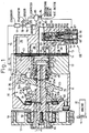
- a single-headed piston type swash plate compressor embodying the present invention for an automotive air conditioning system will be described prior to the description of the construction of a swash plate, which is an essential part of the present invention, and a method of producing the swash plate.
- a clutchless swash plate compressor has a cylinder block 12, a front housing 11 fixedly joined to the front end of the cylinder block 12, and a rear housing 13 fixedly joined to the rear end of the cylinder block 12 with a valve plate 14 sandwiched between the cylinder block 12 and the rear housing 13.
- the front housing 11 and the cylinder block 12 define a crank chamber 15.
- a drive shaft 16 is extended across the crank chamber 15 and is supported for rotation on the front housing 11 and the cylinder block 12.
- a pulley 17 is supported for rotation on an angular-contact bearing 18 mounted on a front end part of the front housing 11, and is fixed to a front end part of the drive shaft 16 projecting from the front housing 11.
- a belt 19 is wound around the pulley 17 to connect the pulley 17 operatively to an engine 20 of a vehicle, i.e., a drive-power source, without using any clutch mechanism, such as a solenoid clutch.
- a lip seal 21 is fitted in a space between the outer circumference of the front end part of the drive shaft 16 and the front housing 11 to seal the front end of the crank chamber 15.
- a rotating support member 22 is fixedly mounted on the drive shift 16 in the crank chamber 15.
- a swash plate 23, i.e., a cam plate, is arranged in the crank chamber 15.
- the drive shaft 16 is extended through a central through hole 23a, formed in the swash plate 23 to support the swash plate thereon, so that the swash plate 23 is able to slide axially along and to incline to the axis L1 of the drive shaft 16.
- the rotating support member 22 and the swash plate 23 are interlocked by a hinge mechanism 10.
- the swash plate 23 is provided with a counterweight 23b on the opposite side of the hinge mechanism 10 with respect to the drive shaft 16.
- the hinge mechanism 10 comprises a pair of support arms 24 (only one of them is shown) projecting from the rear surface of the rotating support member 22, and a pair of guide pins 25 (only one of them is shown) projecting from the front surface of the swash plate 23.
- Each support arm 24 is provided in its end part with a guide hole 24a
- each guide pin 25 is provided in its end part with a spherical part 25a.
- the spherical parts 25a of the guide pins 25 are fitted in the guide holes 24a of the corresponding support arms 24, respectively.
- the swash plate 23 can be inclined to the drive shaft 16 and can be rotated together with the drive shaft by the combined action of the support arms 24 and the guide pins 25.
- the guide holes 24a guide the spherical parts 25a for sliding movement, and the drive shaft 16 allows the swash plate 23 to slide thereon.
- the inclination of the swash plate 23 decreases as the swash plate 23 approaches the cylinder block 12.
- a coil spring 26 wound around the drive shaft 16 and arranged between the rotating support member 22 and the swash plate 23 biases the swash plate 23 toward the cylinder block 12 so as to assist the decrease of the inclination of the swash plate 23.
- a limiting projection 22a formed on the rear surface of the rotating support member 22 comes into contact with a part of the swash plate 23 as shown in Fig. 1 to determine a maximum inclination at which the swash plate 23 can be inclined.
- the cylinder block 12 is provided in its central part with a cavity 27.
- a suction passage 32 is formed in a central part of the rear housing 13 so as to be connected to the cavity 27.
- a positioning surface 33 is formed around one end of the suction passage 32 on the side of the cavity 27.
- the cavity 27 and the suction passage 32 form part of a suction pressure region of the compressor.
- a passage disconnecting piston 28 is fitted slidably in the cavity 27.
- a suction passage opening spring (coil spring) 29 is arranged between the passage disconnecting piston 28 and a shoulder formed in the cavity 27 to bias the passage disconnecting piston 28 toward the swash plate 23.
- a rear end part of the drive shaft 16 is inserted in the passage disconnecting piston 28 and is supported in a radial bearing 30 fitted in the passage disconnecting piston 28.
- the radial bearing 30 is retained in the passage disconnecting piston 28 by a snap ring 31 and is axially movable together with the drive shaft 16 along the axis L.
- the rear end part of the drive shaft 16 is supported in the radial bearing 30 for rotation on the passage disconnecting piston 28 fitted in the cavity 27.
- a closing surface 34 is formed on the rear end of the bottom wall of the passage disconnecting piston 28.
- the closing surface 34 comes into contact with and is separated from the positioning surface 33 as the passage disconnecting piston 28 moves axially.
- the closing surface 34 is in contact with the positioning surface 33, the suction passage 32 is disconnected from a space in the cavity 27.
- a thrust bearing 35 is supported slidably on the drive shaft 16 between the swash plate 23 and the passage disconnecting piston 28.
- the swash plate 23, the thrust bearing 35 and the passage disconnecting piston 28 are kept in contact with each other by the resilience of the coil spring 26 and the suction passage opening spring 29. Therefore, as the swash plate 23 slides toward the passage disconnecting piston 28 and the inclination of the swash plate 23 increases, the passage disconnecting piston 28 is forced to move toward the positioning surface 33 against the resilience of the suction passage opening spring 29 and, eventually, the closing surface 34 of the passage disconnecting piston 28 comes into contact with the positioning surface 33 to limit the further inclination of the swash plate 23. In this state, the swash plate 23 is inclined at a minimum inclination slightly greater than 0°.
- the cylinder block 12 is provided with a plurality of cylinder bores 12a around the drive shaft 16, and single-headed pistons 36 are fitted for reciprocation in the cylinder bores 12a, respectively.
- a front end part of each piston 36 (an end part opposite the compression end surface) is linked by a pair of shoes 37 to a peripheral part of the swash plate 23.
- each piston is operatively connected to the swash plate 23 by the shoes 37 to convert a rotating motion of the swash plate 23 into a reciprocating motion of the piston 36 operatively connected to the swash plate 23 by the shoes 37.
- the rear housing 13 is provided with a substantially annular suction chamber 38, which forms a part of the suction pressure region, and a substantially annular discharge chamber 39, which forms a discharge pressure region, formed around the annular suction chamber 38.
- the suction chamber 38 communicates with the cavity 27 by means of a port 45 formed in the valve plate 14. When the closing surface 34 of the passage disconnecting piston 28 is brought into contact with the positioning surface 33, the port 45 is disconnected from the suction passage 32.
- the valve plate 14 is provided with suction ports respectively opening into the cylinder bores 12a, suction valves 41 respectively for opening and closing the suction ports 40, discharge ports 42, and discharge valves 43 respectively for opening and closing the discharge ports 42.
- a refrigerant gas supplied from an external device into the suction chamber 38 is sucked through the suction port 40 and the suction valve 41 into the cylinder bore 12a by the suction stroke of each piston 36.
- the refrigerant gas taken into the cylinder bore 12a is discharged through the discharge port 42 and the discharge valve 43 by the compression stroke of the piston 36 into the discharge chamber 39.
- a compression reaction force that acts on the rotating support member 22 through the piston 36 when the piston 36 compresses the refrigerant gas is born by a thrust bearing 44 arranged between the rotating support member 22 and the inner surface of the front end wall of the front housing 11.
- a passage 46 is formed in the drive shaft 16 along its axis.
- the passage 46 has a front end 46a opening into a region near the lip seal 21 in the crank chamber 15, and a rear end 46b opening into a space defined by the passage disconnecting piston 28.
- the passage disconnecting piston 28 is provided in its side wall with a pressure relief passage 47 opening into the cavity 27.
- the passage 46 and the pressure relief passage 47 form a bleed passage.
- a supply passage 48 is formed through the cylinder block 12 and the rear housing 13 to connect the discharge chamber 39 and the crank chamber 15.
- a capacity control valve 49 is placed in the supply passage 48.
- a pressure sensing passage 50 is formed in the rear housing 13 so as to connect the capacity control valve 49 and the suction passage 32.
- valve housing 51 and a solenoid unit 52 are joined together in a middle part of the capacity control valve 49.
- a valve chamber 53 is formed between the valve housing and the solenoid unit 52.
- a valve element 54 is placed in the valve chamber 53.
- a valve hole is extended along the axis of the valve housing 51 and opposite to the valve element 54.
- a valve opening spring 56 is placed between the valve element 54 and a wall defining the valve chamber 53 to bias the valve element 54 in a direction to open the valve hole 55.
- the valve chamber 53 communicates with the discharge chamber 39 by means of the supply passage 48.
- a pressure sensing chamber 58 is formed in an upper part of the valve housing 51 and is connected to the pressure sensing passage 50.
- a bellows 60 i.e., a pressure sensing device, is contained in the pressure sensing chamber 58.
- the pressure sensing chamber 58 and the valve chamber 53 are separated from each other by a partition wall 57 of the valve housing 51, and a through hole 61 is formed in the partition wall 57 to connect the chambers 58 and 53.
- a section of the through hole 61 on the side of the valve element 54 serves as the valve hole 55.
- a pressure sensing rod 62 is slidably fitted in the through hole 61.
- the valve element 54 and the bellows 60 are operatively connected by the pressure sensing rod 62.
- a section of the pressure sensing rod 62 on the side of the valve element 54 is reduced to form a passage for the refrigerant gas in the valve hole 55.
- a port 63 is formed in the valve housing 51 in a part between the valve chamber 53 and the pressure sensing chamber 58 so as to intersect the valve hole 55 perpendicularly.
- the port 63 communicates with the crank chamber 15 by means of the supply passage 48; that is, the valve chamber 53, the valve hole 55 and the port 63 are parts of the supply passage 48.
- a stationary core 64 is fitted in an upper part of a core chamber 65 formed in the solenoid unit 52 to define a solenoid chamber 66.
- a movable core 67 having the shape of a bottomed cylinder is fitted axially movably in the solenoid chamber 66.
- a spring 68 is arranged between the movable core 67 and the bottom wall of the core chamber 65. The spring constant of the spring 68 is smaller than that of the valve opening spring 56.
- the stationary core 64 is provided with an axial through hole 69 opening into the solenoid chamber and the valve chamber 53.
- a solenoid rod 70 formed integrally with the valve element 54 is fitted slidably in the through hole 69.
- One end of the solenoid rod 70 on the side of the movable core 67 is held in contact with the movable core 67 by the biasing forces of the valve opening spring 56 and the spring 68.
- the movable core 67 and the valve element 54 are connected operatively by the solenoid rod 70.
- a cylindrical solenoid 74 is arranged around the stationary core 64 and the movable core 67 so as to extend over both the cores 64 and 67.
- the swash plate compressor is connected to an external refrigerant circuit 76 by the suction passage 32 through which the refrigerant gas is taken into the suction chamber 38, and a discharge flange 75 through which the refrigerant gas is discharged from the discharge chamber 39.
- the external refrigerant circuit 76 is provided with a condenser 77, an expansion valve 78 and an evaporator 79.
- the swash plate compressor, the condenser 77, the expansion valve 78 and the evaporator 79 are the components of the automotive air conditioning system.
- An evaporator temperature sensor 81, a passenger compartment temperature sensor 82, an air conditioning system operating switch 83, a passenger compartment temperature setting device 84 and the solenoid 74 of the capacity control valve 49 are connected to a control computer 85.
- the control computer 85 controls the current to be supplied to the solenoid 74 on the basis of measured temperatures measured by the temperature sensors 81 and 82, a signal indicating the condition of the air conditioning system operating switch 83, and a set temperature signal indicating a set temperature set by operating the passenger compartment temperature setting device 84.
- the control computer 85 gives a command to energize the solenoid 74. Then a predetermined current is supplied to the solenoid 74, and an attraction of a magnitude proportional to the current supplied to the solenoid 74 acts between the cores 64 and 67. The attraction is transmitted through the solenoid rod 70 to the valve element 54 and acts in a direction to reduce the opening of the capacity control valve 49 against the resilience of the valve opening spring 56.
- a movable end of the bellows 60 is displaced according to the variation of the suction pressure prevailing in the suction passage 32 and acting through the pressure sensing passage 50 on the pressure sensing chamber 58.
- the bellows 60 responds to the suction pressure when the solenoid 74 is energized.
- the displacement of the movable end of the bellows is transmitted through the pressure sensing rod 62 to the valve element 54.
- the opening of the capacity control valve 49 is dependent on the balance of the force produced by the solenoid unit 52, the force produced by the bellows 60 and the force produced by the valve opening spring 56.
- the difference between the passenger compartment temperature measured by the passenger compartment temperature senior 82 and the set temperature set by the passenger compartment temperature setting device 84 is large when cooling load is high.
- the control computer 85 controls the current to be supplied to the solenoid 74 to vary the set-suction pressure on the basis of the measured passenger compartment temperature and the set passenger compartment temperature; that is, the control computer 85 increases the current according to the increase of the difference between the measured passenger compartment temperature and the set passenger compartment temperature. Consequently, the attraction acting between the stationary core 64 and the movable core 67 increases to increase the force acting on the valve element 54 to reduce the opening of the capacity control valve 49, and the valve element 54 is operated for an opening and closing operation at a lower suction pressure.
- the capacity control valve 49 operates to hold the suction pressure on a lower level when the current supplied to the solenoid 74 is increased.
- the control computer 85 gives a command to supply lower currents for lower passenger chamber temperature. Therefore, the attraction acting between the stationary core 64 and the movable core 67 is low and the force acting on the valve element 54 in a direction to reduce the opening of the capacity control valve 49 is reduced.
- the valve element 45 is operated for opening and closing by a higher suction pressure.
- the capacity control valve 49 operates to hold the suction pressure on a higher level when the current supplied to the solenoid 74 is reduced.
- the control computer 85 provides a command to de-energize the solenoid 74.
- the control computer 85 provides a command to de-energize the solenoid 74 also when the air conditioning system control switch 83 is opened.
- the operation of the capacity control valve 49 varies according to the intensity of the electric current supplied to the solenoid 74.
- the capacity control valve 49 is operated at a low suction pressure when the electric current is large and is operated at a high suction pressure when the electric current is small.
- the compressor changes the angle of inclination of the swash plate 23 and its discharge capacity to maintain the suction pressure at the set suction pressure. Namely, the capacity control valve 49 operates for both changing the set suction pressure by changing the input current and making the compressor operate at its minimum capacity regardless of the suction pressure.
- the compressor provided with the capacity control valve 49 changes the refrigerating capacity of a refrigeration circuit.
- the closing surface 34 of the passage disconnecting piston 28 comes into contact with the positioning surface 33 to disconnect the suction passage 32 from the cavity 27.
- the effective sectional area of the suction passage 32 is zero and the flow of the refrigerant gas from the external refrigerant circuit 76 into the suction chamber 38 is intercepted.
- the minimum angle of inclination of the swash plate 23 is slightly greater than 0°.
- the swash plate 23 is inclined at the minimum inclination when the passage disconnecting piston 28 is located at a disconnecting position where the passage disconnecting piston 28 disconnects the suction passage 32 from the cavity 27.
- the position of the passage disconnecting piston 28 varies between the disconnecting position and a connecting position to connect the suction passage 32 and the cavity 27 according to the variation of the inclination of the swash plate 23.
- the refrigerant gas is discharged from the cylinder bores 12a into the discharge chamber 39 while the compressor is operating with the swash plate 23 inclined at the minimum inclination.
- the refrigerant gas discharged from the cylinder bores 12a into the discharge chamber 39 flows through the supply passage 48 into the crank chamber 15 and flows further through the passage 46 and the pressure relief passage 47 into the suction chamber 38. Then the refrigerant gas is taken from the suction chamber 38 into the cylinder bores 12a and then discharged again into the discharge chamber 39.
- a circulation circuit passing the discharge chamber 39, i.e., the discharge pressure region, the supply passage 48, the crank chamber 15, the passage 46, the pressure relief passage 47, the cavity 27, the suction chamber 38, i.e., the suction pressure region, and the cylinder bores 12a is formed in the compressor when the swash plate 23 is inclined at the minimum inclination.
- the discharge chamber 39, and the crank chamber 15 and the suction chamber 38 there is pressure difference between the discharge chamber 39, and the crank chamber 15 and the suction chamber 38. Therefore, lubricating oil entailed by the refrigerant gas can be supplied to the sliding surfaces of the components of the compressor as the refrigerant' gas circulates through the circulating circuit.
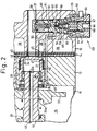
- the swash plate 23 has a central land part 91 and a peripheral part 92 surrounding the land part 91 and having the shape of a flange.
- the thickness of the land part 91 is greater than that of the peripheral part 92.
- the land part 91 is provided with the central through hole 23a and the counterweight 23b.
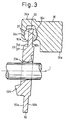
- the peripheral part 92 of the swash plate 23 has a front surface 92a facing the rotating support member 22 arranged in the crank chamber 15, and a rear surface 92b facing the head parts 36a of the single-headed pistons 36. As shown in Figs.
- the tail end part 36b of each single-headed piston 36 opposite the head part 36a of the same is provided with a pair of spherical surfaces 36c for guiding the pair of shoes 37 for sliding movement along a guide circle indicate by long and short dash lines in Fig. 4.
- the shoes 37 are held between the pair of spherical surfaces 36c and the peripheral part 92 of the swash plate 23 inserted in the space between the spherical surfaces 36c.
- the shoes 37 are held for turning on the tail end part 36b of the single-headed piston 36, and the tail end part 36b is linked to the peripheral part 92 of the swash plate 23 by the shoes 37.
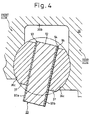
- Figure 4 illustrates surface layers formed on the opposite surfaces 92a and 92b of the peripheral part 92 of the swash plate 23.
- a front layer 93 is formed on the front surface of the peripheral part 92
- a first rear layer 94 is formed on the rear surface of the peripheral part 92
- a second rear layer 95 is formed on the first rear layer 94.
- the front layer 93 is the outermost surface layer on the front side of the swash plate 23.
- the second rear layer 95 is the outermost surface layer on the rear side of the swash plate 23, and the first rear layer 94 is an intermediate layer sandwiched between the outermost layer and the peripheral part of the swash plate 23.
- a part of the swash plate 23 excluding the front layer 93, the first rear layer 94 and the second rear layer 95, i.e., a part consisting of the land part 91 and the peripheral part 92, will be called a 'body'.
- the body of the swash plate 23 is made of an iron-base or an aluminum-base material.
- Each of the single-headed pistons 36 is made of an aluminum-base material in a lightweight member.
- the shoes 37 are made of an iron-base material, such as a bearing steel.
- the term, 'iron-base material' indicates pure iron or an alloy containing iron as a principal component
- the term, 'aluminum-base material' indicates pure aluminum, an alloy containing aluminum as a principal component or an intermetallic compound containing aluminum.
- Aluminum alloys suitable for forming the body of the swash plate are Al-Si alloys, Al-Si-Mg alloys, Al-Si-Cu-Mg alloys and aluminum alloys not containing Si.
- the front layer 93 and the first rear layer 94 are formed of the same material.
- the front layer 93 and the first rear layer 94 are copper-base alloy layers, tin-base alloy layers or alumite layers (layers formed by the anodic oxidation of aluminum), depending on the material of the body (91, 92).
- the respective thicknesses of the front layer 93 and the first rear layer 94 are in the range of 2 to 500 micrometers ( ⁇ m).
- the copper-base alloy layers are formed by a metal spraying process.
- the metal spraying process may be conducted by either a method of forming a layer in which a molten metal produced by entirely melting a metal powder to be sprayed is solidified or a method of partly melting a metal powder to be sprayed without changing the structure of the metal powder.
- pure copper Cu
- the Cu-base alloy may contain 2 through 30% by weight lead (Pb), which provides conformability and a low frictional property.
- the Cu-base alloy may further contain 0.1% by weight or less phosphorus (P) and 5% by weight of less silver (Ag).
- a copper spraying process applicable to the present invention is described in detail in International Publication WO95/25224.
- the tin-base alloy layers of a tin-base alloy can be formed by a similar metal spraying process.
- a pure tin may be used instead of the tin-base alloy.
- the alumite layers can be formed by subjecting the body of an aluminum-base material to a standard anodizing process.
- the thickness of the alumite layer i.e., an anodic coating
- the anodic coating is dense, hard and has high abrasion resistance and excellent adhesion to a base of an aluminum alloy.
- the second rear layer 95 i.e., an outermost rear layer, is a solid lubricant layer containing a solid lubricant at least in a part thereof.
- the thickness of the solid lubricant layer is in the range of 0.5 through 50 ⁇ m, more preferably, in the range of 0.5 through 10 ⁇ m.
- the solid lubricant layer is a layer of an inorganic or an organic solid lubricant or a resin layer containing an inorganic or an organic solid lubricant.
- Possible inorganic solid lubricants are molybdenum disulfide, tungsten disulfide, graphite, boron nitride, antimony oxide, lead oxide, lead (Pb), indium (In) and tin (Sn).
- Possible organic solid lubricants are fluorocarbon resins, such as polytetrafluoroethylene resins (PTFE resins), and unsaturated polyester resins.
- a copper-base alloy containing 5 through 10% by weight Sn and 1 through 10% by weight Pb was sprayed at a powder feed rate of 50 gram/min with a spraying gun (Diamond jet gun available from the manufacturing company in Japan, named "Daiichi Metakon") over the opposite surfaces of the body of an iron-base material of a swash plate.
- the front and the rear surface of the peripheral part 92 of the body were ground, after the sprayed copper-base alloy coatings cooled off, to form a front layer 93 and a first rear layer 94 of about 150 ⁇ m in thickness.
- the surfaces of the front layer 93 and the first rear layer 94 were cleaned and degreased, and then the surface of the first rear layer 94 was coated with a coating layer of a material prepared by dispersing molybdenum disulfide particles of particle sizes in the range of 0.5 through 20 ⁇ m in a polyamidimide resin by a spray coating process.
- the coating layer was baked at 200°C.
- the rear surface 92b of the peripheral part of the swash plate was ground to form a 10 ⁇ m thick second rear layer 95.
- the swash plate thus fabricated was incorporated into the foregoing single-headed piston type swash plate compressor and the single-headed piston type swash plate compressor was operated for the operational suitability test of the swash plate.
- a lubricating oil was supplied at a rate equal to about 10% of a rate at which the lubricating oil is supplied for the practical operation of the single-headed piston type swash plate compressor, and the drive shaft 16 was rotated at about 3,000 rpm for fifteen minutes.
- the front and the rear surface of the swash plate was observed to examine the front and rear surfaces for cracking and seizing after the operational suitability test. No defect was found.
- a tin-base alloy was sprayed at a powder feed rate of 50 gram/min with the same spraying gun over the opposite surfaces of the body of an iron-base material of a swash plate.
- the front and the rear surface of the peripheral part 92 were ground, after the sprayed tin-base alloy coatings cooled off, to form a front layer 93 and a first rear layer 94 of about 150 ⁇ m in thickness.
- the surfaces of the front layer 93 and the first rear layer 94 were cleaned and degreased, and then the surface of the first rear layer 94 was coated with a coating layer of a material prepared by dispersing molybdenum disulfide particles of particle sizes in the range of 0.5 to 20 ⁇ m in a polyamidimide resin by a spray coating process.
- the coating layer was baked at 200°C.
- the rear surface 92b of the swash plate was ground to form a 10 ⁇ m thick second rear layer 95.
- the swash plate thus produced was incorporated into the foregoing single-headed piston type swash plate compressor and the single-headed piston type swash plate compressor was operated for the same operational suitability test of the swash plate. No defects, such as cracks and abrasively damaged parts in the layers, were found.
- Tin-base alloy coatings were formed by plating on the opposite surfaces of the body of an aluminum-base material of a swash plate.
- the front and the rear surface of the peripheral part 92 were ground to form a front layer 93 and a first rear layer 94 of about 150 ⁇ m in thickness.
- the surfaces of the front layer 93 and the first rear layer 94 were cleaned and degreased, and then the surface of the first rear layer 94 was coated with a coating layer of a material prepared by dispersing molybdenum disulfide particles of particle sizes in the range of 0.5 through 20 ⁇ m in a polyamidimide resin by a spray coating process.
- the coating layer was baked at 200°C.
- the rear surface 92b of the peripheral part of the swash plate was ground to form a 10 ⁇ m thick second rear layer 95.
- the swash plate thus produced was incorporated into the foregoing single-headed piston type swash plate compressor and the single-headed piston type swash plate compressor was operated for the same operational suitability test of the swash plate. No defects, such as cracks and abrasively damaged parts, were found.
- the body of an aluminum-base material of a swash plate was immersed in a sulfuric acid solution or an oxalic acid solution and was subjected to an anodizing process to form an oxide film (alumite layer) over the surface of the body made of the aluminum-base material.
- the body of the swash plate was washed with water.
- the respective measured thicknesses of the alumite layers forming the front layer 93 and the rear layer 94 were about 15 ⁇ m.
- the surfaces of the alumite layers were cleaned and degreased, and then the surface of the first rear layer 94 was coated with a coating layer of a material prepared by dispersing molybdenum disulfide particles of particle sizes in the range of 0.5 through 20 ⁇ m in a polyamidimide resin by a spray coating process.
- the coating layer was baked at 200°C.
- the rear surface 92b of the peripheral part of the swash plate was ground to form a 10 ⁇ m thick second rear layer 95.
- the swash plate thus fabricated was incorporated into the foregoing single-headed piston type swash-plate-operated refrigerant compressor and the single-headed piston type swash-plate-operated refrigerant compressor was operated for the same operational suitability test of the swash plate. No defects, such as cracks and abrasively damaged parts, were found.
- a body made of an aluminum-base material of a swash plate was cleaned and degreased, and only the rear surface of the body was roughened by a sand blasting process. Only the rear surface of the body was coated with a coating layer of a material prepared by dispersing molybdenum disulfide particles of particle sizes in the range of 0.5 through 20 ⁇ m in a polyamidimide resin by a transfer coating process. The coating layer was baked at 200°C. The rear surface 92b of the swash plate was ground to form a 10 ⁇ m thick solid lubricant layer of the polyamidimide resin containing molybdenum disulfide.
- the swash plate in Example 5 does have any layers corresponding to the front layer 93 and the first rear layer 94 of the swash plate in Example 4, and the solid lubricant layer of the polyamidimide resin containing molybdenum disulfide corresponding to the second rear layer 95 is formed directly on the body of the aluminum-base material.
- the surface roughness Rz of the body of the swash plate is in the range of 0.4 through 15 ⁇ m, more preferably, in the range of 4 through 10 ⁇ m.
- the surface roughening process improves the adhesion of the solid lubricant layer to the surface of the body.
- the transfer coating method applies a resin containing a solid lubricant to a transfer surface of a transfer pad, and presses the transfer surface of the transfer pad against the surface of the body of the swash plate to transfer the resin containing a solid lubricant from the transfer surface to the surface of the body of the swash plate.
- the swash plate thus produced was incorporated into the foregoing single-headed piston type swash plate compressor and the single-headed piston type swash plate compressor was operated for the same operational suitability test of the swash plate. No defects, such as cracks and abrasively damaged parts, were found.
- a tin-base alloy coating was formed by plating only on the rear surfaces of the body of an aluminum-base material of a swash plate.
- a peripheral part 92 was ground to form a first rear layer 94 of about 150 ⁇ m in thickness.
- the surface of the plated first rear layer 94 was cleaned and degreased, and then the surface of the first rear layer 94 was coated with a coating layer of a material prepared by dispersing molybdenum disulfide particles of particle sizes in the range of 0.5 through 20 ⁇ m in a polyamidimide resin by a spray coating process.
- the coating layer was baked at 200°C.
- the rear surface 92b of the swash plate was ground to form a 10 ⁇ m thick second rear layer 95.
- the swash plate thus produced was incorporated into the foregoing single-headed piston type swash plate compressor and the single-headed piston type swash plate compressor was operated for the see operational suitability test of the swash plate. No defects, such as cracks and abrasively damaged parts, were found in the front and the rear surface of the swash plate.
- the body of an aluminum-base material of a swash plate was immersed in a sulfuric acid solution or an oxalic acid solution and was subjected to an anodizing process using the body as an anode to form an oxide film (alumite layer) over the rear surface of the body made of the aluminum-base material.
- the body of the swash plate was washed with water.
- the measured thickness of the alumite layer forming the rear layer 94 was about 15 ⁇ m.
- the surface of the alumite layer was cleaned and degreased, and then the surface of the first rear layer 94 was coated with a Coating layer of a material prepared by dispersing molybdenum disulfide particles of particle sizes in the range of 0.5 through 20 ⁇ m in a polyamidimide resin by a spray coating process.
- the coating layer was baked at 200°C.
- the rear surface 92b of the swash plate was ground to form a 10 ⁇ m thick second rear layer 95.
- the swash plate thus produced was incorporated into the foregoing single-headed piston type swash plate compressor and the single-headed piston type swash plate compressor was operated for the same operational suitability test of the swash plate. No defects, such as cracks and abrasively damaged parts, were found.
- a swash plate in Comparative example 1 was produced by coating a body similar to that of the swash plate in Example 1 with only the same front layer 93 and the same first rear layer 94 as those of the copper-base alloy of Example 1 formed by the metal spraying process.
- the swash plate in Comparative example 1 corresponds to a swash plate obtained by omitting the second rear layer 95 of the polyamidimide resin containing molybdenum disulfide from the swash plate in Example 1.
- the swash plate was incorporated into the foregoing single-headed piston type swash plate compressor and the single-headed piston type swash plate compressor was operated for the same operational suitability test of the swash plate. Cracks were found in the first rear surface 94 of the copper-base alloy formed by metal spraying.
- a swash plate in Comparative example 2 was produced by coating a body similar to that of the swash plate in Example 4 with only the same front layer 93 and the same first rear layer 94 as those of alumite of Example 4.
- the swash plate in Comparative example 2 corresponds to a swash plate obtained by omitting the second rear layer 95 of the polyamidimide resin containing molybdenum disulfide from the swash plate in Example 4.
- the swash plate was incorporated into the foregoing single-headed piston type swath plate compressor and the single-headed piston type swash plate compressor was operated for the same operational suitability test of the swash plate. Abrasively damaged parts were found in the first rear surface 94 of alumite.
- the swash plates in Examples 1 to 7 are provided with the solid lubricant layer (a layer of a polyamidimide resin containing molybdenum disulfide) only on the rear side of the peripheral part 92.
- the thickness of the solid lubricant layer is adjusted to 10 ⁇ m by grinding after forming a solid lubricant coating and baking the solid lubricant coating.
- the solid lubricant layer is ground for thickness adjustment by using the front surface 92a, i.e., the surface of the front layer 93 not coated with any solid lubricant layer, as a reference plane as illustrated in Fig. 5.
- Such thickness adjustment is possible because the front surface of the peripheral part 92 of the swash plate is not provided with any solid lubricant layer.
- the advantage of forming said lubricant layers only on the rear side of the peripheral part of the swash plate is apparent as contrasted with the disadvantage of forming solid lubricant layers on both sides of the peripheral part 92 of the swash plate
- Figure 6 illustrates a swash plate formed by forming first layers 96a and 96b, such as sprayed layers of copper or tin or alumite layers, on the front and the rear side of a peripheral part 92 of the body of a swash plate, and forming second layers 97a and 97b, i.e., solid lubricant layers, on the first layers 96a and 96b, respectively.
- first layers 96a and 96b such as sprayed layers of copper or tin or alumite layers
- second layers 97a and 97b i.e., solid lubricant layers
- the rear end surface 91a of the land part 91 is used as a reference plane, a block gage 98 is put on the reference plane, the tip of the plunger of a dial indicator 99 is brought into contact with the surface of the solid lubricant layer 97b.
- the height H1 of the rear end surface 91a, i.e., the reference plane, from the surface of the solid lubricant layer 97b is compared with the height H2 of the same from the surface of the first layer 96a.
- the thickness of the solid lubricant layer 97a on the front side of the peripheral part 92 is measured and managed similarly.
- a surface apart from the measured surface must be used as the reference plane when the solid lubricant layers are formed respectively on both the sides of the peripheral part 92 and, therefore, the improvement of accuracy in thickness measurement is limited and hence the severe management of the thickness of the layer and hence that of the thickness of the swash plate is difficult.
- the surface of the front layer 92 finished by grinding and not coated with any layer can be used as the reference plane.
- the front layer 93 and the first rear layer 94 are formed and finished by grinding, and the distance between the surface of the front layer 93 and that of the first rear surface 94, i.e., a primary thickness T1, is measured by using the surface of front layer 93 as a reference plane.
- the second rear layer 95 is formed on the first rear layer 94, and the distance between the surface of the front layer 93 and that of the second rear layer 95, i.e., a secondary thickness T2, is measured.
- the thickness of the second rear layer 95 can be accurately determined by calculating the difference (T2 - T1), i.e., the difference between the secondary thickness T2 and the primary thickness T1. Since the surface nearest to the peripheral part 92 which needs thickness management can be used as the reference plane in the construction shown in Fig. 5, accuracy in measuring the thickness of the layer can be improved, severe control of the thickness of the layer can be achieved, and the control of the thickness of the swash plate can easily be achieved.
- the swash plate 23 has a large inertia.
- the large inertia of the swash plate does not deteriorate the response of the swash plate for changing its inclination even when the clutchless compressor unavoidably operates at a high operating speed according to the operation of the engine 20 at a high engine speed.
- the accuracy of the thickness of the swash plate is secured and the compression efficiency of the single-headed piston type swash plate compressor is reliably improved while the slide-friction between the swash plate and the shoes is improved and the antiseizing property and the abrasion resistance of the swash plate are improved.
- the swash plate production method of the present invention facilitates the controlling of the thickness of the swash plate of the single-headed piston type swash-plate-operated compressor even if the swash plate is provided on its rear side with the solid lubricant layer for improving the slide-friction between the rear surface of the swash plate and the shoes, which enables machining accuracy in adjusting the thickness of the swash plate to a desired value.
Landscapes
- Engineering & Computer Science (AREA)
- Mechanical Engineering (AREA)
- General Engineering & Computer Science (AREA)
- Compressors, Vaccum Pumps And Other Relevant Systems (AREA)
Applications Claiming Priority (2)
| Application Number | Priority Date | Filing Date | Title |
|---|---|---|---|
| JP9360155A JPH11193780A (ja) | 1997-12-26 | 1997-12-26 | 片頭ピストン型斜板式圧縮機および斜板の製造方法 |
| JP36015597 | 1997-12-26 |
Publications (3)
| Publication Number | Publication Date |
|---|---|
| EP0926340A2 true EP0926340A2 (fr) | 1999-06-30 |
| EP0926340A3 EP0926340A3 (fr) | 2000-05-24 |
| EP0926340B1 EP0926340B1 (fr) | 2004-08-04 |
Family
ID=18468148
Family Applications (1)
| Application Number | Title | Priority Date | Filing Date |
|---|---|---|---|
| EP98124481A Expired - Lifetime EP0926340B1 (fr) | 1997-12-26 | 1998-12-23 | Revêtement du palier d'un plateau en biais |
Country Status (4)
| Country | Link |
|---|---|
| US (1) | US6189434B1 (fr) |
| EP (1) | EP0926340B1 (fr) |
| JP (1) | JPH11193780A (fr) |
| DE (1) | DE69825406T2 (fr) |
Cited By (14)
| Publication number | Priority date | Publication date | Assignee | Title |
|---|---|---|---|---|
| EP1106704A1 (fr) * | 1999-12-01 | 2001-06-13 | Visteon Global Technologies, Inc. | Revêtements sans plomb, à base de cuivre et contenant du bismuth pour compresseurs à plateau oscillant |
| WO2002029249A1 (fr) * | 2000-10-03 | 2002-04-11 | Kabushiki Kaisha Toyota Jidoshokki | Plateau oscillant de compresseur a plateau oscillant |
| WO2002075172A1 (fr) * | 2001-03-16 | 2002-09-26 | Taiho Kogyo Co., Ltd. | Materiau de glissement |
| US6543333B2 (en) | 2001-06-01 | 2003-04-08 | Visteon Global Technologies, Inc. | Enriched cobalt-tin swashplate coating alloy |
| EP1256717A3 (fr) * | 2001-05-10 | 2003-05-28 | Kabushiki Kaisha Toyota Jidoshokki | Patin pour un compresseur à plateau en biais |
| EP1188923A3 (fr) * | 2000-09-18 | 2003-06-18 | Kabushiki Kaisha Toyota Jidoshokki | Revêtement d'un plateau-came d'un compresseur |
| EP1128065A3 (fr) * | 2000-02-22 | 2003-09-17 | Kabushiki Kaisha Toyota Jidoshokki | Application d'un revêtement lubrifiant sur un plateau en biais d'un compresseur |
| EP1134413A3 (fr) * | 2000-03-17 | 2004-01-02 | Kabushiki Kaisha Toyota Jidoshokki | Plateau en biais pour un compresseur |
| EP1482075A1 (fr) * | 2003-05-29 | 2004-12-01 | Dana Corporation | Revêtement d'un segment de piston |
| EP1251274A3 (fr) * | 2001-04-20 | 2004-12-22 | Kabushiki Kaisha Toyota Jidoshokki | Plateau en biais pour un compresseur |
| EP1508693A3 (fr) * | 2003-08-18 | 2011-06-22 | Senju Metal Industry Co., Ltd. | Revêtement de palier multicouches et sa méthode de fabrication |
| EP2669399A1 (fr) * | 2012-06-01 | 2013-12-04 | Sulzer Metco AG | Partie de stockage ainsi que procédé de pulvérisation thermique |
| EP2832997A4 (fr) * | 2012-03-29 | 2016-03-30 | Taiho Kogyo Co Ltd | Plateau oscillant |
| EP2832995A4 (fr) * | 2012-03-26 | 2016-03-30 | Taiho Kogyo Co Ltd | Plateau oscillant |
Families Citing this family (28)
| Publication number | Priority date | Publication date | Assignee | Title |
|---|---|---|---|---|
| JP2000257555A (ja) * | 1999-03-08 | 2000-09-19 | Toyota Autom Loom Works Ltd | 圧縮機 |
| JP3251562B2 (ja) * | 1999-07-09 | 2002-01-28 | 大豊工業株式会社 | 斜板式コンプレッサーの斜板 |
| JP2001041150A (ja) * | 1999-07-27 | 2001-02-13 | Toyota Autom Loom Works Ltd | 機械部品における皮膜形成方法 |
| JP2001065452A (ja) * | 1999-08-26 | 2001-03-16 | Toyota Autom Loom Works Ltd | ダイカストピストンおよびそれの製造方法 |
| JP2001234860A (ja) | 2000-02-22 | 2001-08-31 | Toyota Autom Loom Works Ltd | 圧縮機の皮膜形成対象部品及び皮膜形成対象部品における皮膜形成方法 |
| JP2001335812A (ja) * | 2000-03-24 | 2001-12-04 | Senju Metal Ind Co Ltd | 鉛フリー平軸受およびその製造方法 |
| JP2002005013A (ja) | 2000-06-27 | 2002-01-09 | Toyota Industries Corp | 斜板式圧縮機 |
| US6582200B2 (en) * | 2000-07-14 | 2003-06-24 | Kabushiki Kaisha Toyoda Jidoshokki Seisakusho | Swash plate compressor having shoes made of a magnesium-based material |
| EP1172556A3 (fr) * | 2000-07-14 | 2004-05-12 | Kabushiki Kaisha Toyota Jidoshokki | Disposition de patin glissant pour compresseur à plateau en biais |
| JP2002138954A (ja) * | 2000-08-24 | 2002-05-17 | Zexel Valeo Climate Control Corp | 回転斜板式圧縮機 |
| JP2002115657A (ja) | 2000-10-05 | 2002-04-19 | Toyota Industries Corp | ピストン式圧縮機におけるシリンダ |
| JP2002126850A (ja) * | 2000-10-23 | 2002-05-08 | Chuetsu Metal Works Co Ltd | 可変容量圧縮機用複合斜板の製造方法 |
| JP2002295473A (ja) | 2001-03-28 | 2002-10-09 | Senju Metal Ind Co Ltd | 鉛フリージャーナル軸受 |
| JP4496662B2 (ja) * | 2001-04-20 | 2010-07-07 | 株式会社豊田自動織機 | 斜板式圧縮機における斜板 |
| JP2003172254A (ja) * | 2001-12-06 | 2003-06-20 | Sanden Corp | 斜板式圧縮機 |
| US7025167B2 (en) * | 2002-02-15 | 2006-04-11 | Automotive Components Holdings, Llc | Shaft to transfer torque in a vehicle |
| JP2003278742A (ja) * | 2002-03-26 | 2003-10-02 | Daido Metal Co Ltd | 両面摺動スラスト軸受 |
| JP2004251256A (ja) * | 2003-02-21 | 2004-09-09 | Sanden Corp | 斜板式圧縮機 |
| US7331274B2 (en) | 2004-05-21 | 2008-02-19 | Kabushiki Kaisha Toyota Jidoshokki | Sliding film, sliding member, composition for sliding film, sliding device, swash-plate type compressor, process for forming sliding film, and process for producing sliding member |
| KR100619592B1 (ko) | 2004-10-19 | 2006-09-13 | 재단법인 포항산업과학연구원 | 가변식 압축기 사판의 제조를 위한 용사코팅용 합금재 및 이를 이용한 가변식 압축기 사판의 제조방법 |
| US7281465B2 (en) * | 2006-01-09 | 2007-10-16 | Delphi Technologies, Inc. | Compressor piston ball pocket coating |
| DE102007001793A1 (de) * | 2007-01-05 | 2008-07-10 | Robert Bosch Gmbh | Hydraulische Kolbenmaschine |
| JP5033432B2 (ja) | 2007-01-30 | 2012-09-26 | 株式会社豊田自動織機 | 摺動部品 |
| JP2008274762A (ja) | 2007-04-25 | 2008-11-13 | Toyota Industries Corp | 圧縮機用斜板及びその製造方法 |
| JP2011017269A (ja) * | 2009-07-08 | 2011-01-27 | Valeo Thermal Systems Japan Corp | 斜板式圧縮機 |
| JP5190473B2 (ja) * | 2010-02-09 | 2013-04-24 | 本田技研工業株式会社 | 複層潤滑被膜用組成物及び内燃機関のピストン |
| CN103629074A (zh) * | 2012-08-24 | 2014-03-12 | 苏州轩昌机电科技有限公司 | 压缩机斜盘及其制造方法和工装模具 |
| CN103470475A (zh) * | 2013-09-26 | 2013-12-25 | 常熟市淼泉压缩机配件有限公司 | 一种旋转斜盘式空调压缩机的斜盘 |
Citations (4)
| Publication number | Priority date | Publication date | Assignee | Title |
|---|---|---|---|---|
| JPS6022080A (ja) | 1983-07-15 | 1985-02-04 | Taiho Kogyo Co Ltd | 斜板式コンプレツサ |
| JPH0510513A (ja) | 1991-06-28 | 1993-01-19 | Noritz Corp | 燃焼装置 |
| WO1995025224A1 (fr) | 1994-03-16 | 1995-09-21 | Taiho Kogyo Co., Ltd. | Plateau oscillant de compresseur du type a plateau oscillant |
| JPH08199327A (ja) | 1995-01-27 | 1996-08-06 | Taiho Kogyo Co Ltd | 斜板式コンプレッサーの斜板 |
Family Cites Families (7)
| Publication number | Priority date | Publication date | Assignee | Title |
|---|---|---|---|---|
| JPS6019972A (ja) * | 1983-07-13 | 1985-02-01 | Taiho Kogyo Co Ltd | 斜板式コンプレツサ |
| JPH0697033B2 (ja) | 1988-11-11 | 1994-11-30 | 株式会社豊田自動織機製作所 | 斜板式圧縮機 |
| US5630355A (en) * | 1993-06-21 | 1997-05-20 | Kabushiki Kaisha Toyoda Jidoshokki Seisakusho | Reciprocating type compressor with improved cylinder block |
| JP3568061B2 (ja) * | 1995-05-17 | 2004-09-22 | 大豊工業株式会社 | 斜板式コンプレッサーの斜板及び斜板とシューとの組合わせ |
| US5655432A (en) * | 1995-12-07 | 1997-08-12 | Ford Motor Company | Swash plate with polyfluoro elastomer coating |
| JPH09209926A (ja) * | 1996-01-29 | 1997-08-12 | Calsonic Corp | 斜板式コンプレッサ |
| JP3695724B2 (ja) * | 1996-03-19 | 2005-09-14 | カルソニックカンセイ株式会社 | 斜板式コンプレッサの片頭式ピストンの製造方法 |
-
1997
- 1997-12-26 JP JP9360155A patent/JPH11193780A/ja active Pending
-
1998
- 1998-12-23 DE DE69825406T patent/DE69825406T2/de not_active Expired - Lifetime
- 1998-12-23 US US09/221,288 patent/US6189434B1/en not_active Expired - Fee Related
- 1998-12-23 EP EP98124481A patent/EP0926340B1/fr not_active Expired - Lifetime
Patent Citations (4)
| Publication number | Priority date | Publication date | Assignee | Title |
|---|---|---|---|---|
| JPS6022080A (ja) | 1983-07-15 | 1985-02-04 | Taiho Kogyo Co Ltd | 斜板式コンプレツサ |
| JPH0510513A (ja) | 1991-06-28 | 1993-01-19 | Noritz Corp | 燃焼装置 |
| WO1995025224A1 (fr) | 1994-03-16 | 1995-09-21 | Taiho Kogyo Co., Ltd. | Plateau oscillant de compresseur du type a plateau oscillant |
| JPH08199327A (ja) | 1995-01-27 | 1996-08-06 | Taiho Kogyo Co Ltd | 斜板式コンプレッサーの斜板 |
Cited By (24)
| Publication number | Priority date | Publication date | Assignee | Title |
|---|---|---|---|---|
| EP1106704A1 (fr) * | 1999-12-01 | 2001-06-13 | Visteon Global Technologies, Inc. | Revêtements sans plomb, à base de cuivre et contenant du bismuth pour compresseurs à plateau oscillant |
| US6926779B1 (en) | 1999-12-01 | 2005-08-09 | Visteon Global Technologies, Inc. | Lead-free copper-based coatings with bismuth for swashplate compressors |
| EP1128065A3 (fr) * | 2000-02-22 | 2003-09-17 | Kabushiki Kaisha Toyota Jidoshokki | Application d'un revêtement lubrifiant sur un plateau en biais d'un compresseur |
| EP1134413A3 (fr) * | 2000-03-17 | 2004-01-02 | Kabushiki Kaisha Toyota Jidoshokki | Plateau en biais pour un compresseur |
| EP1188923A3 (fr) * | 2000-09-18 | 2003-06-18 | Kabushiki Kaisha Toyota Jidoshokki | Revêtement d'un plateau-came d'un compresseur |
| EP1331394A4 (fr) * | 2000-10-03 | 2003-09-17 | Toyoda Automatic Loom Works | Plateau oscillant de compresseur a plateau oscillant |
| WO2002029249A1 (fr) * | 2000-10-03 | 2002-04-11 | Kabushiki Kaisha Toyota Jidoshokki | Plateau oscillant de compresseur a plateau oscillant |
| EP1281881A4 (fr) * | 2001-03-16 | 2011-03-02 | Taiho Kogyo Co Ltd | Materiau de glissement |
| WO2002075172A1 (fr) * | 2001-03-16 | 2002-09-26 | Taiho Kogyo Co., Ltd. | Materiau de glissement |
| US6921205B2 (en) | 2001-03-16 | 2005-07-26 | Taiho Kogyo Co., Ltd. | Sliding material |
| EP1251274A3 (fr) * | 2001-04-20 | 2004-12-22 | Kabushiki Kaisha Toyota Jidoshokki | Plateau en biais pour un compresseur |
| EP1256717A3 (fr) * | 2001-05-10 | 2003-05-28 | Kabushiki Kaisha Toyota Jidoshokki | Patin pour un compresseur à plateau en biais |
| US6543333B2 (en) | 2001-06-01 | 2003-04-08 | Visteon Global Technologies, Inc. | Enriched cobalt-tin swashplate coating alloy |
| EP1482075A1 (fr) * | 2003-05-29 | 2004-12-01 | Dana Corporation | Revêtement d'un segment de piston |
| EP1508693A3 (fr) * | 2003-08-18 | 2011-06-22 | Senju Metal Industry Co., Ltd. | Revêtement de palier multicouches et sa méthode de fabrication |
| EP2832995A4 (fr) * | 2012-03-26 | 2016-03-30 | Taiho Kogyo Co Ltd | Plateau oscillant |
| US9528504B2 (en) | 2012-03-26 | 2016-12-27 | Taiho Kogyo Co., Ltd. | Swash plate |
| EP2832997A4 (fr) * | 2012-03-29 | 2016-03-30 | Taiho Kogyo Co Ltd | Plateau oscillant |
| EP2669400A1 (fr) * | 2012-06-01 | 2013-12-04 | Sulzer Metco AG | Poudre mouillable sans zinc, couche de diffusion thermique contenant du cuivre, ainsi que procédé de génération d'une couche de diffusion thermique cuivreuse |
| CN103453018A (zh) * | 2012-06-01 | 2013-12-18 | 苏舍美特科公司 | 轴承部件和热喷涂方法 |
| US9097276B2 (en) | 2012-06-01 | 2015-08-04 | Oerlikon Metco Ag | Bearing part and thermal spray method |
| EP2669399A1 (fr) * | 2012-06-01 | 2013-12-04 | Sulzer Metco AG | Partie de stockage ainsi que procédé de pulvérisation thermique |
| CN103453018B (zh) * | 2012-06-01 | 2017-10-13 | 苏舍美特科公司 | 轴承部件和热喷涂方法 |
| US9885382B2 (en) | 2012-06-01 | 2018-02-06 | Oerlikon Metco Ag, Wohlen | Zinc-free spray powder, copper-containing thermal spray layer, as well as method of manufacturing a copper-containing thermal spray layer |
Also Published As
| Publication number | Publication date |
|---|---|
| DE69825406T2 (de) | 2005-06-30 |
| EP0926340B1 (fr) | 2004-08-04 |
| EP0926340A3 (fr) | 2000-05-24 |
| US6189434B1 (en) | 2001-02-20 |
| DE69825406D1 (de) | 2004-09-09 |
| JPH11193780A (ja) | 1999-07-21 |
Similar Documents
| Publication | Publication Date | Title |
|---|---|---|
| EP0926340B1 (fr) | Revêtement du palier d'un plateau en biais | |
| US6378415B1 (en) | Compressor | |
| JP3918516B2 (ja) | 斜板式圧縮機 | |
| US6308615B1 (en) | Compressor | |
| EP1281863B1 (fr) | Revêtement de compresseur | |
| EP0844390B1 (fr) | Compresseur à plateau en biais comportant un plateau en matériel très résistant à l'usure | |
| US6289785B1 (en) | Swash plate type compressor | |
| US20020104432A1 (en) | Compressor and sliding member thereof | |
| EP1167761A2 (fr) | Compresseur à plateau en biais | |
| EP1253318A2 (fr) | Patin pour un compresseur à plateau en biais | |
| EP1134413A2 (fr) | Plateau en biais pour un compresseur | |
| EP1251274B1 (fr) | Plateau en biais pour un compresseur | |
| US20030000379A1 (en) | Shoe and the same for swash plate type compressor | |
| US20020046647A1 (en) | Compressors | |
| KR20030043605A (ko) | 압축기용 슬라이딩재 | |
| EP1342919A2 (fr) | Patin pour un compresseur à plateau en biais et procédé de fabrication du patin | |
| EP0943800A1 (fr) | Compresseur a plateau oscillant | |
| US20020046646A1 (en) | Compressors | |
| EP1158163A2 (fr) | Piston pour compresseur à plateau en biais | |
| JP2003183685A (ja) | 摺動部材 | |
| EP1092873A2 (fr) | Alésages dans le cylindre d'un compresseur à plateau en biais | |
| JPH0783169A (ja) | 密閉形電動圧縮機およびその製造方法 |
Legal Events
| Date | Code | Title | Description |
|---|---|---|---|
| PUAI | Public reference made under article 153(3) epc to a published international application that has entered the european phase |
Free format text: ORIGINAL CODE: 0009012 |
|
| AK | Designated contracting states |
Kind code of ref document: A2 Designated state(s): DE FR IT |
|
| AX | Request for extension of the european patent |
Free format text: AL;LT;LV;MK;RO;SI |
|
| PUAL | Search report despatched |
Free format text: ORIGINAL CODE: 0009013 |
|
| AK | Designated contracting states |
Kind code of ref document: A3 Designated state(s): AT BE CH CY DE DK ES FI FR GB GR IE IT LI LU MC NL PT SE |
|
| AX | Request for extension of the european patent |
Free format text: AL;LT;LV;MK;RO;SI |
|
| 17P | Request for examination filed |
Effective date: 20000707 |
|
| AKX | Designation fees paid |
Free format text: DE FR IT |
|
| RAP1 | Party data changed (applicant data changed or rights of an application transferred) |
Owner name: KABUSHIKI KAISHA TOYOTA JIDOSHOKKI |
|
| 17Q | First examination report despatched |
Effective date: 20030218 |
|
| GRAP | Despatch of communication of intention to grant a patent |
Free format text: ORIGINAL CODE: EPIDOSNIGR1 |
|
| GRAS | Grant fee paid |
Free format text: ORIGINAL CODE: EPIDOSNIGR3 |
|
| GRAA | (expected) grant |
Free format text: ORIGINAL CODE: 0009210 |
|
| AK | Designated contracting states |
Kind code of ref document: B1 Designated state(s): DE FR IT |
|
| REF | Corresponds to: |
Ref document number: 69825406 Country of ref document: DE Date of ref document: 20040909 Kind code of ref document: P |
|
| ET | Fr: translation filed | ||
| PLBE | No opposition filed within time limit |
Free format text: ORIGINAL CODE: 0009261 |
|
| STAA | Information on the status of an ep patent application or granted ep patent |
Free format text: STATUS: NO OPPOSITION FILED WITHIN TIME LIMIT |
|
| 26N | No opposition filed |
Effective date: 20050506 |
|
| PGFP | Annual fee paid to national office [announced via postgrant information from national office to epo] |
Ref country code: IT Payment date: 20101224 Year of fee payment: 13 |
|
| PGFP | Annual fee paid to national office [announced via postgrant information from national office to epo] |
Ref country code: FR Payment date: 20111219 Year of fee payment: 14 |
|
| PGFP | Annual fee paid to national office [announced via postgrant information from national office to epo] |
Ref country code: DE Payment date: 20111221 Year of fee payment: 14 |
|
| REG | Reference to a national code |
Ref country code: FR Ref legal event code: ST Effective date: 20130830 |
|
| REG | Reference to a national code |
Ref country code: DE Ref legal event code: R119 Ref document number: 69825406 Country of ref document: DE Effective date: 20130702 |
|
| PG25 | Lapsed in a contracting state [announced via postgrant information from national office to epo] |
Ref country code: DE Free format text: LAPSE BECAUSE OF NON-PAYMENT OF DUE FEES Effective date: 20130702 |
|
| PG25 | Lapsed in a contracting state [announced via postgrant information from national office to epo] |
Ref country code: FR Free format text: LAPSE BECAUSE OF NON-PAYMENT OF DUE FEES Effective date: 20130102 |
|
| PG25 | Lapsed in a contracting state [announced via postgrant information from national office to epo] |
Ref country code: IT Free format text: LAPSE BECAUSE OF NON-PAYMENT OF DUE FEES Effective date: 20121223 |