EP0926451B1 - Appareil pour chauffage et refroidissement encastré dans un plafond - Google Patents
Appareil pour chauffage et refroidissement encastré dans un plafond Download PDFInfo
- Publication number
- EP0926451B1 EP0926451B1 EP97830721A EP97830721A EP0926451B1 EP 0926451 B1 EP0926451 B1 EP 0926451B1 EP 97830721 A EP97830721 A EP 97830721A EP 97830721 A EP97830721 A EP 97830721A EP 0926451 B1 EP0926451 B1 EP 0926451B1
- Authority
- EP
- European Patent Office
- Prior art keywords
- air
- wall
- rotatable
- heat exchange
- louver
- Prior art date
- Legal status (The legal status is an assumption and is not a legal conclusion. Google has not performed a legal analysis and makes no representation as to the accuracy of the status listed.)
- Expired - Lifetime
Links
- 238000001816 cooling Methods 0.000 title claims description 33
- 238000010438 heat treatment Methods 0.000 title claims description 30
- 238000012545 processing Methods 0.000 description 3
- 239000004793 Polystyrene Substances 0.000 description 2
- 230000008859 change Effects 0.000 description 2
- 229920002223 polystyrene Polymers 0.000 description 2
- 238000011144 upstream manufacturing Methods 0.000 description 2
- 238000004378 air conditioning Methods 0.000 description 1
- 230000004075 alteration Effects 0.000 description 1
- 230000001143 conditioned effect Effects 0.000 description 1
- 230000007423 decrease Effects 0.000 description 1
- 230000006872 improvement Effects 0.000 description 1
- 230000007774 longterm Effects 0.000 description 1
- 238000005259 measurement Methods 0.000 description 1
- 238000000034 method Methods 0.000 description 1
- 238000012986 modification Methods 0.000 description 1
- 230000004048 modification Effects 0.000 description 1
- 239000004033 plastic Substances 0.000 description 1
- 230000008569 process Effects 0.000 description 1
- 230000003134 recirculating effect Effects 0.000 description 1
Images




Classifications
-
- F—MECHANICAL ENGINEERING; LIGHTING; HEATING; WEAPONS; BLASTING
- F24—HEATING; RANGES; VENTILATING
- F24F—AIR-CONDITIONING; AIR-HUMIDIFICATION; VENTILATION; USE OF AIR CURRENTS FOR SCREENING
- F24F13/00—Details common to, or for air-conditioning, air-humidification, ventilation or use of air currents for screening
- F24F13/08—Air-flow control members, e.g. louvres, grilles, flaps or guide plates
- F24F13/081—Air-flow control members, e.g. louvres, grilles, flaps or guide plates for guiding air around a curve
-
- F—MECHANICAL ENGINEERING; LIGHTING; HEATING; WEAPONS; BLASTING
- F24—HEATING; RANGES; VENTILATING
- F24F—AIR-CONDITIONING; AIR-HUMIDIFICATION; VENTILATION; USE OF AIR CURRENTS FOR SCREENING
- F24F1/00—Room units for air-conditioning, e.g. separate or self-contained units or units receiving primary air from a central station
- F24F1/0007—Indoor units, e.g. fan coil units
- F24F1/0018—Indoor units, e.g. fan coil units characterised by fans
- F24F1/0022—Centrifugal or radial fans
-
- F—MECHANICAL ENGINEERING; LIGHTING; HEATING; WEAPONS; BLASTING
- F24—HEATING; RANGES; VENTILATING
- F24F—AIR-CONDITIONING; AIR-HUMIDIFICATION; VENTILATION; USE OF AIR CURRENTS FOR SCREENING
- F24F1/00—Room units for air-conditioning, e.g. separate or self-contained units or units receiving primary air from a central station
- F24F1/0007—Indoor units, e.g. fan coil units
- F24F1/0043—Indoor units, e.g. fan coil units characterised by mounting arrangements
- F24F1/0047—Indoor units, e.g. fan coil units characterised by mounting arrangements mounted in the ceiling or at the ceiling
-
- F—MECHANICAL ENGINEERING; LIGHTING; HEATING; WEAPONS; BLASTING
- F24—HEATING; RANGES; VENTILATING
- F24F—AIR-CONDITIONING; AIR-HUMIDIFICATION; VENTILATION; USE OF AIR CURRENTS FOR SCREENING
- F24F1/00—Room units for air-conditioning, e.g. separate or self-contained units or units receiving primary air from a central station
- F24F1/0007—Indoor units, e.g. fan coil units
- F24F1/0059—Indoor units, e.g. fan coil units characterised by heat exchangers
-
- F—MECHANICAL ENGINEERING; LIGHTING; HEATING; WEAPONS; BLASTING
- F24—HEATING; RANGES; VENTILATING
- F24F—AIR-CONDITIONING; AIR-HUMIDIFICATION; VENTILATION; USE OF AIR CURRENTS FOR SCREENING
- F24F13/00—Details common to, or for air-conditioning, air-humidification, ventilation or use of air currents for screening
- F24F13/02—Ducting arrangements
-
- F—MECHANICAL ENGINEERING; LIGHTING; HEATING; WEAPONS; BLASTING
- F24—HEATING; RANGES; VENTILATING
- F24F—AIR-CONDITIONING; AIR-HUMIDIFICATION; VENTILATION; USE OF AIR CURRENTS FOR SCREENING
- F24F13/00—Details common to, or for air-conditioning, air-humidification, ventilation or use of air currents for screening
- F24F13/02—Ducting arrangements
- F24F13/06—Outlets for directing or distributing air into rooms or spaces, e.g. ceiling air diffuser
- F24F2013/0616—Outlets that have intake openings
Definitions
- This invention relates to heating or cooling apparatus mounted within a suspended ceiling in a home, office, or other building space.
- this invention relates to the processing of air through such apparatus.
- the ceiling mounted apparatus typically includes a fan device for drawing in the air that is to be processed and discharged.
- This fan device may create a significant suction pressure at the air inlet. This suction pressure can draw the air being discharged from the ceiling mounted apparatus back into the apparatus. Re-circulation of this discharged air back through the heat exchange elements lowers the heating or cooling efficiency of the apparatus. It may also affect the long term integrity of the heat exchange elements that are being exposed to the re-circulated air that does not need to be further heated or cooled.
- US-A-5 577 958 discloses a wind direction adjusting device having a deflecting guide in the wind path.
- DE-01-29601794 discloses an air-conditioning unit having a de deflecting device in the flow path.
- JP-A-01 075823 describes an air-conditioner having a wind deflector in the air discharge passage.
- JP-A-08 100 942 describes an air-conditioner having a pivoting horizontal blade at the air-outlet part. It has however been found that this directional discharge is hard to achieve when the air outlets are relatively close to the air inlet.
- a ceiling mounted heating or cooling apparatus draws air upwardly into an inlet and processes the air through heat exchange elements before distributing the air downwardly.
- the air is preferably distributed downwardly by air discharge structure surrounding the heat exchange elements.
- the air is ultimately discharged through one or more air discharge ducts positioned relatively close to the air inlet.
- Each discharge duct includes a rotatable louver mounted therein that guides the air within the duct.
- a wall of each discharge duct includes a smoothly curved bend of a prescribed angular arc that directs the discharged air away from the air inlet of the apparatus. This wall in each duct is relatively close to the air inlet.
- the rotatable louver in each air discharge duct preferably rotates between either of two positions depending on whether warm or cool air is to be discharged.
- the position of the louver when warm air is to be discharged produces a substantially downward air flow path to the air exiting the duct.
- the position of the louver when cool air is to be discharged produces a substantially lateral air flow path to the air exiting the duct.
- the air is preferably discharged at a minimum distance from the ceiling so as to avoid any smudging of the ceiling. This is accomplished by a gradually curved wall in each air duct that extends laterally outwardly so as to define where the air exits from the duct at the minimum distance from the ceiling.
- a ceiling mounted apparatus 10 for heating or cooling air is illustrated in mounted position with respect to a ceiling 12.
- the apparatus is seen to include a centrally located air intake grill 14, which allows air to be drawn in from the space being heated or cooled.
- the heating and cooling apparatus also includes four air ' discharge slots 16, 18, 20 and 22. These air discharge slots each form part of respective air discharge ducts which distribute processed air from the apparatus back into the space being heated or cooled. It is to be noted that each discharge slot is located relatively close to the centrally located grill 14.
- the heating and cooling apparatus 10 is shown before being mounted within the ceiling 12. It is to be noted that the heating and cooling apparatus includes a housing 24 containing the various components for processing the air that is drawn into the apparatus through the air intake grill 14.
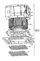
- the heating and cooling apparatus 10 is illustrated in an exploded view form.
- the bottom portion of the heating and cooling apparatus is seen to include a frame 26 in which four air discharge ducts, such as duct 28, are formed .
- Each discharge duct defines one of the respective discharge slots 16, 18, 20 and 22 in the frame 26.
- a rotatable louver such as 30 is positioned within each air discharge duct.
- the rotatable louver 30 is seen to extend along the entire length of the duct 28.
- An air filter 32 and the intake grill 14 preferably fit into a central opening in the frame 26 and are appropriately secured thereto.
- the intake grill 14 is preferably square in shape and is curved slightly upwardly toward its center from all four sides.
- a centrifugal fan 34 draws air upwardly through the intake grill 14 and the air filter 32. This fan distributes the drawn up air radially outwardly toward heat exchange elements 36.
- the heat exchange elements preferably consist of a series of coils arranged around the periphery of the centrifugal fan. These coils carry a heat exchange medium which transfers heat to or from a series of heat exchange fins in thermal conducting contact with the coils.
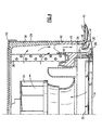
- the outwardly flowing air from the centrifugal flow fan 32 is deflected downwardly by air channel structure 38 as shown in Figure 4.
- the air channel structure 38 is preferably molded out of polystyrene so as to form a single light insulative piece that fits into the housing 24.
- the air channel structure 38 is seen to extend inwardly along a top portion 40 of the heating and cooling apparatus to a point beyond the inner perimeter of the fins of the heat exchange elements.
- the air channel structure also extends downwardly along the inner wall of the housing 24.
- the air channel structure 38 also is slanted toward the inner wall of the housing 24 so as to define a continuously increasing radial spacing from the heat exchange elements.
- the air channel structure 38 extends downwardly at this definable slant to the top of a drain pan 42 that is more clearly shown in Figure 3.
- the bottoms of the fins of the heat exchange elements 36 rest in the drain pan 42 so as to allow any condensate from the coils of the heat exchange elements to be collected and drained away in a slot 44.
- a slotted hole 45 in the drain pan is aligned with respect to the air channel structure 38 so as to define a continuous air channel down to the air duct 28 formed in the frame 26. It is to be noted that similar slotted holes in the drain pan define continuous air channels down to the other respective air discharge ducts in the frame 26.
- the cross-section of the frame in Figure 4 reveals that the frame consists of two different structures.
- the frame includes an exterior portion 46 preferably molded of a hard plastic.
- the frame furthermore includes a lightweight molded polystyrene structure 47 above the exterior portion 46.
- this structure forms a continuous, smooth, inner wall surface for deflecting the air downwardly.
- the upper portion of this continuous, smooth, inner wall surface is preferably a curved arc having a constant radius of curvature.
- the slanted portion of this inner wall is preferably three to five degrees from the vertical. This smooth continuous inner wall assures that all air flows smoothly down to the slotted hole 46 in the drain pan and hence to the air passage duct 28 formed in the frame 26.
- the heating or cooling apparatus will either provide warm or cool air to the air discharge ducts in the frame 26.
- the louver 30 is attached at each end to rotatable members such as 48 which rotates within a bracket 50.
- the louver 30 is rotated to either of two positions depending on whether warm or cool air is flowing through the air discharge duct 28.
- the rotation of the louver 30 may either be by a motor or through manual adjustment.
- similar louvers are rotatably mounted and driven to respective positions in each of the other air discharge ducts formed in the frame 26.
- the air discharge duct 28 within the frame 26 is further illustrated in an enlarged cross-sectional view.
- the air discharge duct 28 is seen to comprise two continuous wall surfaces denoted as an inner wall surface 52 and an outer wall surface 54.
- the inner wall surface 52 is relatively close to the intake grill 14 whereas the outer wall surface 54 is further away from the grill.
- the outer wall surface 54 is seen to be a part of the frame 26 that extends outwardly in a lateral direction away from the portion of the frame 26 that fits up into the ceiling. This portion of the frame forms a lip 56 that generally fits up against the ceiling when the heating or cooling apparatus is mounted thereto. It is to be noted that the outer wall 54 extends outwardly to a point located at a distance "h" below the top of the lip 56.
- the distance "h” is preferably in the range of fifteen to twenty millimeters. This height assures that no smudging will occur to the ceiling when air flows out along the smoothly curved wall 54. It is finally to be noted that the beginning of the outer wall surface 54 is substantially vertical before sharply curving to a point where the lip 56 begins. This point is vertically below where the frame 26 fits into the ceiling. The outer wall surface continues almost laterally from this point at a substantially large radius of curvature until reaching the discharge point at the distance "h" below the top of the lip 56 of the frame 26.
- this wall begins within the frame 26 upstream of where the louver 30 is rotatably mounted within the duct 28. This wall slants slightly from vertical to a point vertically below the horizontal plane containing the axis of rotation of the rotatable member 48.
- the inner wall 52 thereafter comprises a substantially curved arc before tangentially meeting a straight slanted wall surface immediately upstream of the exit point of the air from the duct 28.
- the total angular change of the inner wall 52 from the first slanted portion of this wall beginning where the duct 28 is formed in the frame 26 to the second slanted straight wall portion ending where the air exits from the duct 28 is denoted by the angle ⁇ .
- This angle is determined by the curved arc portion of the inner wall 52 that joins the first and second slanted wall portions of the inner wall.
- This angular change in the inner wall 52 is preferably within the range of one hundred ten to one hundred thirty degrees. It has been found that when ⁇ is greater than one hundred thirty degrees, there is the potential for re-circulation of the air back into the inlet grill 14. It has also been found that when ⁇ is less than one hundred ten degrees, there is a poor discharge of heated air.
- this louver comprises two leg portions joined together by a curved arc portion therebetween.
- the curved arc portion defines an angle ⁇ between the two straight leg portions of the louver.
- the curved arc portion preferably has a constant radius of curvature so that the angle ⁇ defines the total angular measurement in degrees of arc defined by such a radius.
- the angle ⁇ is preferably in the range of one hundred ten to one hundred twenty degrees.
- the two straight leg portions of the louver 30 preferably define linear dimensions "A" and "B". These linear dimensions are defined by extending the center lines of these leg portions until they intersect at a point in the vicinity of the curved arc portion.
- the dimension "A” is measured from the tip of the upper leg portion along the center line of this upper leg portion of the louver to the aforementioned point of intersection of the center lines.
- the dimension "B” is measured along the center line of the lower straight leg portion from the aforementioned point of intersection to the tip of the lower leg of the louver.
- the ratio "A/B" of these dimensions is preferably in the range of 0.4 to 0.6. It has been found that an A/B ratio of less than 0.4 produces poor discharge of air with the potential for re-circulation problems with respect to the air intake grill 14. An A/B ratio greater than 0.6 creates a louver that is too sensitive to rotational positioning.
- the louver 30 is shown in Figure 5 in its normal position for processing cooled air within the air discharge duct 28.
- the point of intersection of the dimensioned lengths "A" and “B” of the louver is preferably at a lateral distance "F” from the point of the inner wall 52 where the curved arc portion begins.
- the point of intersection of the lengths "A” and “B” of the louver is also at a lateral distance "G” from the top most point of the outer wall 54.
- the ratio of these dimensions, F/G is preferably between 0.8 and 1.2.
- the lower leg of the louver 30 during cooling is preferably at an angle ⁇ of sixty to seventy-five degrees from vertical. This angle allows for substantial air flow to either side of the louver. This thus positioned louver produces a directional discharge of air from the duct 28 defined by the angle ⁇ .
- the angle ⁇ as measured from horizontal will be between five and twenty degrees when the lower leg of the louver is at the angle ⁇ .
- the louver 30 is illustrated in the heating mode position.
- the louver 30 has been preferably rotated clockwise by twenty-five degrees from the cooling mode position so that the lower leg portion moves toward the inner wall 52 whereas the upper leg portion moves towards the outer wall 54.
- the lower leg portion of the louver 30 is now at a angle ⁇ of thirty-five to fifty degrees from vertical.
- the thus positioned louver now tends to deflect the air from its otherwise normal outward flow dictated by the slant of the inner wall 52 at the air exit point from the duct 28.
- the lower leg of the louver 30 tends to deflect the heated air substantially downwardly with less of a lateral component than when the louver 30 is in the cooling mode position.
- the angle of discharge, 0, is preferably in the range of forty to fifty-five degrees from horizontal. It is to be noted that this angle has a lateral component that is substantially less than the lateral component of the angle ⁇ defining the air discharge direction in the cooling mode.
- This angular slope is denoted as ⁇ in Figure 6.
- This angle as measured from vertical is preferably midway between a given value of K and a given value of ⁇ used in a particularly designed duct. This normally results in the angle ⁇ being in the range of fifty-five to sixty-five degrees. This allows the air flow closest to the inner wall to have a substantial lateral component in both heating and cooling so as to reduce the risk of any recirculating air to the air intake grill 14.
- angles ⁇ and ⁇ denoting the angular arc of curvature of the inner wall surface 52 and the louver 30, respectively. It is to be noted that these angular arcs allow for a substantial air flow along the inner wall 52 of the air duct 28 in both heating and cooling. If the angle ⁇ of the arc of the inner wall is however less than one hundred-ten degrees, then the exit slope angle ⁇ of this wall increases thereby producing excessive pressure loss on the inner wall side of the louver during heating mode. On the other hand, if the angle ⁇ is greater than one hundred-thirty degrees, then the exit slope ⁇ decreases to the point where discharged air may recirculate into the grill.
- the thus shaped air duct passage 28 in combination with the thus shaped louver 30 defines two separate distinct air paths to either side of the louver. These paths produce a first directional air discharge for cooling versus cooling a second directional discharge for heating.
- the air discharge path for cooling moves the air substantially laterally outwardly from the apparatus so as to avoid creating a cold draft on people within the room being cooled by the ceiling apparatus.
- the air discharge in heating is substantially more downward to counteract the tendency of heated air to normally rise and thereby not circulate toward the people in the room.
Landscapes
- Engineering & Computer Science (AREA)
- Chemical & Material Sciences (AREA)
- Combustion & Propulsion (AREA)
- Mechanical Engineering (AREA)
- General Engineering & Computer Science (AREA)
- Physics & Mathematics (AREA)
- Thermal Sciences (AREA)
- Air-Flow Control Members (AREA)
- Devices For Blowing Cold Air, Devices For Blowing Warm Air, And Means For Preventing Water Condensation In Air Conditioning Units (AREA)
- Air Filters, Heat-Exchange Apparatuses, And Housings Of Air-Conditioning Units (AREA)
- Cold Air Circulating Systems And Constructional Details In Refrigerators (AREA)
Claims (15)
- Appareil (10) montable au plafond pour chauffer ou refroidir de l'air, ledit appareil comprenant :un boítier externe (24) ;un bâti (26) contenant une entrée d'air (14), ledit bâti (26) s'adaptant audit boítier externe (24) ;un ventilateur (34) à l'intérieur du boítier externe (24) pour introduire de l'air vers le haut à travers l'entrée d'air (14) dans ledit bâti (26) et pour distribuer en conséquence l'air introduit radialement vers l'extérieur ;une pluralité d'éléments d'échange de chaleur (36) positionnés radialement vers l'extérieur dudit ventilateur (34) pour chauffer ou refroidir l'air distribué radialement à partir dudit ventilateur (34) ;une structure de canal d'air (38) positionnée à l'intérieur du boítier externe (24) par rapport audit ventilateur (34) afin de dévier l'air distribué radialement à partir dudit ventilateur (34) vers le bas ; etau moins un conduit de décharge d'air (28) dans ledit bâti (26) contenant l'entrée d'air (14), ledit conduit de décharge (28) comprenant une première paroi (52) située à proximité d'au moins un bord de l'entrée d'air (14) et une seconde paroi (54) opposée à ladite première paroi (52) qui est située davantage vers l'extérieur à partir du bord de l'entrée d'air (14) que ladite première paroi (52), dans lequel lesdites première et seconde parois sont lisses, des parois continues formées dans ledit bâti (26), et dans lequel ladite première paroi (52) dans ledit conduit de décharge (28) comprend une première partie de paroi droite suivie d'une partie de paroi courbée suivie d'une seconde partie de paroi droite se terminant où l'air est déchargé à partir du conduit de décharge (28), ladite seconde partie de paroi droite étant à un angle (α) par rapport à ladite première partie de paroi droite afin de diriger l'air déchargé à partir du conduit de décharge (28) éloigné de l'entrée d'air (14).
- Appareil (10) selon la revendication 1, dans lequel la partie de paroi courbée de ladite première paroi (52) définit un arc angulaire (α) dans la plage comprise entre cent-dix et cent-trente degrés entre lesdites première et seconde parties droites de ladite première paroi (52).
- Appareil (10) selon la revendication 1 ou 2, dans lequel la seconde partie de paroi droite se terminant où l'air est déchargé à partir du conduit de décharge (28) est à un angle à partir de la verticale dans la plage comprise entre cinquante-cinq et soixante-cinq degrés.
- Appareil (10) selon l'une quelconque des revendications précédentes, comprenant en outre :un louvre rotatif (30) monté à l'intérieur dudit conduit de décharge (28), ledit louvre rotatif (30) comprenant des première et seconde parties de montant droites qui sont jointes ensembles par une partie d'arc courbée entre elles.
- Appareil (10) selon la revendication 4, dans lequel ladite partie d'arc courbée entre lesdites première et seconde parties de montant droites comprennent un arc (β) dans la plage comprise entre cent-dix et cent-vingt degrés.
- Appareil (10) selon la revendication 4 ou 5, dans lequel les axes desdites première et seconde parties de montant droites se coupent à un point de manière à définir une première longueur de dimension linéaire (A) le long de l'axe du premier montant allant du point d'intersection à la pointe dudit premier montant et une seconde longueur de dimension linéaire (B) le long de l'axe du second montant allant du point d'intersection à la pointe du second montant et dans lequel le rapport de la première longueur de dimension linéaire à la seconde longueur de dimension linéaire (A/B) est dans la plage comprise entre 0,4 et 0,6.
- Appareil (10) selon la revendication 6 dans lequel le louvre rotatif (30) est rotatif dans une première position lorsque l'air est refroidi par lesdits éléments d'échange de chaleur (36), dans laquelle le point d'intersection desdits premier et second axes est à une première distance horizontale (F) allant du point de la première paroi (52) où la première partie de paroi droite se termine et où la partie de paroi courbée commence et à une seconde distance horizontale (G) allant du point supérieur de la seconde paroi (54) formée dans le bâti dans lequel le rapport de la première distance horizontale sur la seconde distance horizontale (F/G) est de 0,8 à 1,2.
- Appareil (10) selon l'une quelconque des revendications 4 à 7, dans lequel la seconde partie de montant droite dudit louvre rotatif (30) est à un angle à partir de la verticale entre soixante et soixante-quinze degrés lorsque ledit louvre rotatif (30) est dans la première position.
- Appareil (10) selon la revendication 7 ou 8, dans lequel ledit louvre rotatif (30) est rotatif dans une seconde position lorsque l'air est chauffé par lesdits éléments d'échange de chaleur (36), dans laquelle la seconde partie de montant droite dudit louvre rotatif (30) est à un angle à partir de la verticale entre trente-cinq et cinquante degrés.
- Appareil (10) selon la revendication 5, dans lequel ledit louvre rotatif (30) est rotatif dans une première position lorsque l'air est refroidi par lesdits éléments d'échange de chaleur (36) dans laquelle la seconde partie de montant droite dudit louvre rotatif (30) est à un angle à partir de la verticale entre soixante et soixante-quinze degrés.
- Appareil (10) selon la revendication 10, dans lequel ledit louvre rotatif (30) est rotatif dans une seconde position lorsque l'air est chauffé par lesdits éléments d'échange de chaleur (36), dans laquelle la seconde partie de montant droite dudit louvre rotatif (30) est à un angle à partir de la verticale entre trente-cinq et cinquante degrés.
- Appareil (10) selon la revendication 1, dans lequel la seconde paroi (54) dans ledit conduit de décharge (28) comprend une partie courbée en continu s'étendant latéralement vers l'extérieur en direction d'un bord extérieur dudit bâti (26), ladite partie courbée définissant le point de sortie d'air le plus proche d'une surface de plafond lorsque l'appareil (10) montable au plafond est monté sur un plafond.
- Appareil (10) selon la revendication 12, dans lequel le point de sortie d'air le plus proche d'une surface de plafond est à une distance verticale de la surface de plafond qui est dans une plage comprise entre quinze et vingt millimètres.
- Appareil (10) selon l'une quelconque des revendications précédentes dans lequel ladite structure de canal d'air (38) positionnée à l'intérieur du boítier externe (24) comprend :une structure continue entourant lesdits éléments d'échange de chaleur (36) et espacée radialement de ceux-ci à des distances radiales croissantes à mesure que ladite structure continue s'étend vers le bas à partir d'un point au-dessus desdits éléments d'échange de chaleur (36) à un point au-dessous desdits éléments d'échange de chaleur (36).
- Appareil (10) selon la revendication 14, dans lequel ladite structure continue se courbe davantage radialement vers l'intérieur au-dessus desdits éléments d'échange de chaleur (36) afin de définir un canal d'air courbé lisse commençant au-dessus desdits éléments d'échange de chaleur (36).
Priority Applications (7)
| Application Number | Priority Date | Filing Date | Title |
|---|---|---|---|
| DE69724627T DE69724627T2 (de) | 1997-12-24 | 1997-12-24 | Deckenmontierte Vorrichtung für Heizung und Kühlung |
| ES97830721T ES2201261T3 (es) | 1997-12-24 | 1997-12-24 | Aparato de calefaccion y refrigeracion montado en el techo. |
| EP97830721A EP0926451B1 (fr) | 1997-12-24 | 1997-12-24 | Appareil pour chauffage et refroidissement encastré dans un plafond |
| SG9803411A SG89263A1 (en) | 1997-12-24 | 1998-09-03 | Ceiling mounted apparatus for heating and cooling |
| JP35526598A JP3408440B2 (ja) | 1997-12-24 | 1998-12-15 | 天井に取り付けられた冷暖房装置 |
| KR1019980057602A KR100303755B1 (ko) | 1997-12-24 | 1998-12-23 | 천장장착식냉난방장치 |
| HK99106123.9A HK1021018B (en) | 1999-12-24 | Ceiling mounted apparatus for heating and cooling |
Applications Claiming Priority (1)
| Application Number | Priority Date | Filing Date | Title |
|---|---|---|---|
| EP97830721A EP0926451B1 (fr) | 1997-12-24 | 1997-12-24 | Appareil pour chauffage et refroidissement encastré dans un plafond |
Publications (2)
| Publication Number | Publication Date |
|---|---|
| EP0926451A1 EP0926451A1 (fr) | 1999-06-30 |
| EP0926451B1 true EP0926451B1 (fr) | 2003-09-03 |
Family
ID=8230924
Family Applications (1)
| Application Number | Title | Priority Date | Filing Date |
|---|---|---|---|
| EP97830721A Expired - Lifetime EP0926451B1 (fr) | 1997-12-24 | 1997-12-24 | Appareil pour chauffage et refroidissement encastré dans un plafond |
Country Status (6)
| Country | Link |
|---|---|
| EP (1) | EP0926451B1 (fr) |
| JP (1) | JP3408440B2 (fr) |
| KR (1) | KR100303755B1 (fr) |
| DE (1) | DE69724627T2 (fr) |
| ES (1) | ES2201261T3 (fr) |
| SG (1) | SG89263A1 (fr) |
Families Citing this family (18)
| Publication number | Priority date | Publication date | Assignee | Title |
|---|---|---|---|---|
| JP3268279B2 (ja) * | 1999-01-18 | 2002-03-25 | 三菱電機株式会社 | 空気調和機 |
| JP3408983B2 (ja) * | 1999-01-25 | 2003-05-19 | 三菱電機株式会社 | 天井埋込型空気調和機 |
| JP3624808B2 (ja) * | 2000-08-11 | 2005-03-02 | ダイキン工業株式会社 | 空気調和装置の化粧パネル、吹出口ユニット、及び空気調和装置 |
| JP3820182B2 (ja) * | 2002-05-10 | 2006-09-13 | 三菱重工業株式会社 | 空調装置のルーバー及び空調装置の気流制御構造、並びに空調装置 |
| EP1589292A1 (fr) * | 2004-04-23 | 2005-10-26 | Unico Consumer Products Co., Ltd. | Appareil de traitement de l'air encastrés dans un plafond |
| JP2014126282A (ja) * | 2012-12-26 | 2014-07-07 | Daikin Ind Ltd | 天井設置型室内機 |
| KR101702169B1 (ko) | 2013-10-02 | 2017-02-02 | 엘지전자 주식회사 | 카세트형 공기조화기의 실내기 |
| KR101706812B1 (ko) | 2013-10-02 | 2017-02-14 | 엘지전자 주식회사 | 카세트형 공기조화기의 실내기 |
| KR20150041340A (ko) * | 2013-10-08 | 2015-04-16 | 엘지전자 주식회사 | 카세트형 공기조화기의 실내기 |
| KR20150043573A (ko) | 2013-10-11 | 2015-04-23 | 엘지전자 주식회사 | 공기조화기의 실내기 |
| KR101662377B1 (ko) | 2014-01-27 | 2016-10-04 | 엘지전자 주식회사 | 공기조화기의 실내기 |
| CN106403016B (zh) | 2015-07-30 | 2019-07-26 | Lg电子株式会社 | 空调机的室内机 |
| WO2017081965A1 (fr) * | 2015-11-12 | 2017-05-18 | 株式会社デンソー | Dispositif d'évacuation d'air |
| CN106403220A (zh) * | 2016-10-27 | 2017-02-15 | 珠海格力电器股份有限公司 | 空调进风格栅安装结构和空调装置 |
| EP3842703A4 (fr) * | 2018-08-21 | 2022-03-30 | Hitachi-Johnson Controls Air Conditioning, Inc. | Unité intérieure pour climatiseur |
| CN112013528A (zh) * | 2019-05-30 | 2020-12-01 | 青岛海尔空调电子有限公司 | 空调器的导风组件 |
| CN112013527A (zh) * | 2019-05-30 | 2020-12-01 | 青岛海尔空调电子有限公司 | 空调器的导风组件 |
| CN113357733B (zh) * | 2021-07-12 | 2024-12-27 | 浙江艾玛特环境设备科技有限公司 | 纤薄设计正反通用的全热交换除霾一体机 |
Family Cites Families (8)
| Publication number | Priority date | Publication date | Assignee | Title |
|---|---|---|---|---|
| JPS6099935A (ja) * | 1983-11-02 | 1985-06-03 | Matsushita Refrig Co | 天井埋込型空気調和機 |
| JPS6099936A (ja) * | 1983-11-02 | 1985-06-03 | Matsushita Refrig Co | 天井埋込型空気調和機 |
| JPS6475823A (en) * | 1987-09-17 | 1989-03-22 | Sanyo Electric Co | Ceiling-embedded type air conditioner |
| JPH0678242A (ja) * | 1992-08-07 | 1994-03-18 | Sony Corp | キードafc回路およびキードパルス有無判別回路 |
| JP3240854B2 (ja) * | 1994-09-26 | 2001-12-25 | 三菱電機株式会社 | 空気調和機の吹出口 |
| JP3269280B2 (ja) * | 1994-09-30 | 2002-03-25 | ダイキン工業株式会社 | 天井埋込型空気調和機 |
| JP3506400B2 (ja) * | 1995-09-22 | 2004-03-15 | 三洋電機株式会社 | 空気調和機 |
| DE29601794U1 (de) * | 1996-02-02 | 1996-03-14 | Gesellschaft für Luftschleieranlagen mbH, 73278 Schlierbach | Deckenlüftungsgerät zum Heizen und Klimatisieren von Räumen |
-
1997
- 1997-12-24 ES ES97830721T patent/ES2201261T3/es not_active Expired - Lifetime
- 1997-12-24 DE DE69724627T patent/DE69724627T2/de not_active Expired - Lifetime
- 1997-12-24 EP EP97830721A patent/EP0926451B1/fr not_active Expired - Lifetime
-
1998
- 1998-09-03 SG SG9803411A patent/SG89263A1/en unknown
- 1998-12-15 JP JP35526598A patent/JP3408440B2/ja not_active Expired - Fee Related
- 1998-12-23 KR KR1019980057602A patent/KR100303755B1/ko not_active Expired - Fee Related
Also Published As
| Publication number | Publication date |
|---|---|
| KR100303755B1 (ko) | 2002-04-17 |
| JPH11248189A (ja) | 1999-09-14 |
| DE69724627T2 (de) | 2004-06-24 |
| HK1021018A1 (en) | 2000-05-26 |
| KR19990066863A (ko) | 1999-08-16 |
| DE69724627D1 (de) | 2003-10-09 |
| JP3408440B2 (ja) | 2003-05-19 |
| ES2201261T3 (es) | 2004-03-16 |
| EP0926451A1 (fr) | 1999-06-30 |
| SG89263A1 (en) | 2002-06-18 |
Similar Documents
| Publication | Publication Date | Title |
|---|---|---|
| US6250373B1 (en) | Ceiling mounted apparatus for heating and cooling | |
| EP0926451B1 (fr) | Appareil pour chauffage et refroidissement encastré dans un plafond | |
| EP1326054B1 (fr) | Panneau decoratif pour systemes de climatisation, unite de sortie d'air, et systeme de climatisation | |
| US12366368B2 (en) | Indoor unit for air conditioner | |
| US6141983A (en) | Air conditioner | |
| EP1041351B1 (fr) | Section interieure pour conditionneur d'air | |
| EP1310743B1 (fr) | Panneau decoratif et unite de diffuseur d'un climatiseur et climatiseur | |
| CN107449040A (zh) | 空调柜机及其控制方法 | |
| EP1316760B1 (fr) | Panneau de decoration pour systeme de climatisation, unite d'echappement d'air de sortie, et systeme de climatisation | |
| CN113217995A (zh) | 壁挂式空调室内机 | |
| US5722484A (en) | Louver assembly for fan discharge duct | |
| EP0962716B1 (fr) | Appareil de conditionnement d'air | |
| HK1021018B (en) | Ceiling mounted apparatus for heating and cooling | |
| JP3081476B2 (ja) | 送風方向制御装置 | |
| CN213514112U (zh) | 空调柜机 | |
| CN211903079U (zh) | 天花机 | |
| US12422149B2 (en) | Air conditioner | |
| KR20070033531A (ko) | 천장형 공기조화기 | |
| JPH0240424A (ja) | 天井埋込型空気調和機 | |
| JP3178579B2 (ja) | 空気調和機 | |
| JP2574592Y2 (ja) | 空調装置 | |
| JPH062876A (ja) | 空調機 | |
| CN119436274A (zh) | 柜式空调器及其控制方法 | |
| CN121140073A (zh) | 空调室内机和空调器 | |
| JP2000199642A (ja) | 空気調和機の整流機構 |
Legal Events
| Date | Code | Title | Description |
|---|---|---|---|
| PUAI | Public reference made under article 153(3) epc to a published international application that has entered the european phase |
Free format text: ORIGINAL CODE: 0009012 |
|
| AK | Designated contracting states |
Kind code of ref document: A1 Designated state(s): DE ES FR GB GR IT NL |
|
| AX | Request for extension of the european patent |
Free format text: AL;LT;LV;MK;RO;SI |
|
| 17P | Request for examination filed |
Effective date: 19991203 |
|
| AKX | Designation fees paid |
Free format text: DE ES FR GB GR IT NL |
|
| 17Q | First examination report despatched |
Effective date: 20020812 |
|
| GRAH | Despatch of communication of intention to grant a patent |
Free format text: ORIGINAL CODE: EPIDOS IGRA |
|
| RIN1 | Information on inventor provided before grant (corrected) |
Inventor name: TETU, LEE G. Inventor name: RABITO, MAURIZIO Inventor name: RUSIGNUOLO, GIORGIO Inventor name: VECCHI, GIANLUCA |
|
| GRAS | Grant fee paid |
Free format text: ORIGINAL CODE: EPIDOSNIGR3 |
|
| GRAA | (expected) grant |
Free format text: ORIGINAL CODE: 0009210 |
|
| AK | Designated contracting states |
Kind code of ref document: B1 Designated state(s): DE ES FR GB GR IT NL |
|
| REG | Reference to a national code |
Ref country code: GB Ref legal event code: FG4D |
|
| REF | Corresponds to: |
Ref document number: 69724627 Country of ref document: DE Date of ref document: 20031009 Kind code of ref document: P |
|
| REG | Reference to a national code |
Ref country code: GR Ref legal event code: EP Ref document number: 20030404586 Country of ref document: GR |
|
| REG | Reference to a national code |
Ref country code: ES Ref legal event code: FG2A Ref document number: 2201261 Country of ref document: ES Kind code of ref document: T3 |
|
| ET | Fr: translation filed | ||
| PLBE | No opposition filed within time limit |
Free format text: ORIGINAL CODE: 0009261 |
|
| STAA | Information on the status of an ep patent application or granted ep patent |
Free format text: STATUS: NO OPPOSITION FILED WITHIN TIME LIMIT |
|
| REG | Reference to a national code |
Ref country code: HK Ref legal event code: GR Ref document number: 1021018 Country of ref document: HK |
|
| 26N | No opposition filed |
Effective date: 20040604 |
|
| PGFP | Annual fee paid to national office [announced via postgrant information from national office to epo] |
Ref country code: NL Payment date: 20071109 Year of fee payment: 11 |
|
| PGFP | Annual fee paid to national office [announced via postgrant information from national office to epo] |
Ref country code: GR Payment date: 20071025 Year of fee payment: 11 |
|
| NLV4 | Nl: lapsed or anulled due to non-payment of the annual fee |
Effective date: 20090701 |
|
| PG25 | Lapsed in a contracting state [announced via postgrant information from national office to epo] |
Ref country code: NL Free format text: LAPSE BECAUSE OF NON-PAYMENT OF DUE FEES Effective date: 20090701 |
|
| PG25 | Lapsed in a contracting state [announced via postgrant information from national office to epo] |
Ref country code: GR Free format text: LAPSE BECAUSE OF NON-PAYMENT OF DUE FEES Effective date: 20090703 |
|
| PGFP | Annual fee paid to national office [announced via postgrant information from national office to epo] |
Ref country code: FR Payment date: 20101224 Year of fee payment: 14 |
|
| PGFP | Annual fee paid to national office [announced via postgrant information from national office to epo] |
Ref country code: GB Payment date: 20101222 Year of fee payment: 14 |
|
| PGFP | Annual fee paid to national office [announced via postgrant information from national office to epo] |
Ref country code: DE Payment date: 20101222 Year of fee payment: 14 |
|
| PGFP | Annual fee paid to national office [announced via postgrant information from national office to epo] |
Ref country code: ES Payment date: 20110120 Year of fee payment: 14 |
|
| PGFP | Annual fee paid to national office [announced via postgrant information from national office to epo] |
Ref country code: IT Payment date: 20111228 Year of fee payment: 15 |
|
| GBPC | Gb: european patent ceased through non-payment of renewal fee |
Effective date: 20111224 |
|
| REG | Reference to a national code |
Ref country code: FR Ref legal event code: ST Effective date: 20120831 |
|
| PG25 | Lapsed in a contracting state [announced via postgrant information from national office to epo] |
Ref country code: GB Free format text: LAPSE BECAUSE OF NON-PAYMENT OF DUE FEES Effective date: 20111224 Ref country code: DE Free format text: LAPSE BECAUSE OF NON-PAYMENT OF DUE FEES Effective date: 20120703 |
|
| REG | Reference to a national code |
Ref country code: DE Ref legal event code: R119 Ref document number: 69724627 Country of ref document: DE Effective date: 20120703 |
|
| PG25 | Lapsed in a contracting state [announced via postgrant information from national office to epo] |
Ref country code: FR Free format text: LAPSE BECAUSE OF NON-PAYMENT OF DUE FEES Effective date: 20120102 |
|
| REG | Reference to a national code |
Ref country code: ES Ref legal event code: FD2A Effective date: 20130704 |
|
| PG25 | Lapsed in a contracting state [announced via postgrant information from national office to epo] |
Ref country code: ES Free format text: LAPSE BECAUSE OF NON-PAYMENT OF DUE FEES Effective date: 20111225 |
|
| PG25 | Lapsed in a contracting state [announced via postgrant information from national office to epo] |
Ref country code: IT Free format text: LAPSE BECAUSE OF NON-PAYMENT OF DUE FEES Effective date: 20121224 |