EP0933444B1 - Dispositif de pulverisation cathodique a magnetron a feuille - Google Patents
Dispositif de pulverisation cathodique a magnetron a feuille Download PDFInfo
- Publication number
- EP0933444B1 EP0933444B1 EP98932581A EP98932581A EP0933444B1 EP 0933444 B1 EP0933444 B1 EP 0933444B1 EP 98932581 A EP98932581 A EP 98932581A EP 98932581 A EP98932581 A EP 98932581A EP 0933444 B1 EP0933444 B1 EP 0933444B1
- Authority
- EP
- European Patent Office
- Prior art keywords
- disk
- chamber
- sputtering chamber
- substrate processing
- sputtering apparatus
- Prior art date
- Legal status (The legal status is an assumption and is not a legal conclusion. Google has not performed a legal analysis and makes no representation as to the accuracy of the status listed.)
- Expired - Lifetime
Links
- 238000001755 magnetron sputter deposition Methods 0.000 title claims abstract description 36
- 239000000758 substrate Substances 0.000 claims abstract description 135
- 238000004544 sputter deposition Methods 0.000 claims abstract description 101
- 230000032258 transport Effects 0.000 claims abstract description 25
- XLYOFNOQVPJJNP-UHFFFAOYSA-N water Substances O XLYOFNOQVPJJNP-UHFFFAOYSA-N 0.000 claims description 15
- 238000001816 cooling Methods 0.000 claims description 13
- 239000000463 material Substances 0.000 claims description 6
- 230000007423 decrease Effects 0.000 claims description 5
- 230000007246 mechanism Effects 0.000 abstract description 13
- 238000000151 deposition Methods 0.000 abstract description 7
- 238000000034 method Methods 0.000 abstract description 3
- 239000000498 cooling water Substances 0.000 description 11
- 239000010949 copper Substances 0.000 description 6
- 238000009826 distribution Methods 0.000 description 6
- RYGMFSIKBFXOCR-UHFFFAOYSA-N Copper Chemical compound [Cu] RYGMFSIKBFXOCR-UHFFFAOYSA-N 0.000 description 5
- 229910052802 copper Inorganic materials 0.000 description 5
- 230000008021 deposition Effects 0.000 description 4
- 238000010893 electron trap Methods 0.000 description 3
- 239000012212 insulator Substances 0.000 description 3
- 238000004519 manufacturing process Methods 0.000 description 3
- 239000013077 target material Substances 0.000 description 3
- XKRFYHLGVUSROY-UHFFFAOYSA-N Argon Chemical compound [Ar] XKRFYHLGVUSROY-UHFFFAOYSA-N 0.000 description 2
- 239000007789 gas Substances 0.000 description 2
- 230000000873 masking effect Effects 0.000 description 2
- 239000000203 mixture Substances 0.000 description 2
- 229910052786 argon Inorganic materials 0.000 description 1
- 230000000903 blocking effect Effects 0.000 description 1
- 230000003247 decreasing effect Effects 0.000 description 1
- 230000000694 effects Effects 0.000 description 1
- 230000003628 erosive effect Effects 0.000 description 1
- 238000002474 experimental method Methods 0.000 description 1
- 238000012423 maintenance Methods 0.000 description 1
- 239000002184 metal Substances 0.000 description 1
- 229910052751 metal Inorganic materials 0.000 description 1
- 239000002245 particle Substances 0.000 description 1
- 238000003825 pressing Methods 0.000 description 1
- 230000002265 prevention Effects 0.000 description 1
- 238000004088 simulation Methods 0.000 description 1
- 229910001220 stainless steel Inorganic materials 0.000 description 1
- 239000010935 stainless steel Substances 0.000 description 1
- 238000009827 uniform distribution Methods 0.000 description 1
Images


Classifications
-
- C—CHEMISTRY; METALLURGY
- C23—COATING METALLIC MATERIAL; COATING MATERIAL WITH METALLIC MATERIAL; CHEMICAL SURFACE TREATMENT; DIFFUSION TREATMENT OF METALLIC MATERIAL; COATING BY VACUUM EVAPORATION, BY SPUTTERING, BY ION IMPLANTATION OR BY CHEMICAL VAPOUR DEPOSITION, IN GENERAL; INHIBITING CORROSION OF METALLIC MATERIAL OR INCRUSTATION IN GENERAL
- C23C—COATING METALLIC MATERIAL; COATING MATERIAL WITH METALLIC MATERIAL; SURFACE TREATMENT OF METALLIC MATERIAL BY DIFFUSION INTO THE SURFACE, BY CHEMICAL CONVERSION OR SUBSTITUTION; COATING BY VACUUM EVAPORATION, BY SPUTTERING, BY ION IMPLANTATION OR BY CHEMICAL VAPOUR DEPOSITION, IN GENERAL
- C23C14/00—Coating by vacuum evaporation, by sputtering or by ion implantation of the coating forming material
- C23C14/22—Coating by vacuum evaporation, by sputtering or by ion implantation of the coating forming material characterised by the process of coating
- C23C14/34—Sputtering
- C23C14/35—Sputtering by application of a magnetic field, e.g. magnetron sputtering
-
- C—CHEMISTRY; METALLURGY
- C23—COATING METALLIC MATERIAL; COATING MATERIAL WITH METALLIC MATERIAL; CHEMICAL SURFACE TREATMENT; DIFFUSION TREATMENT OF METALLIC MATERIAL; COATING BY VACUUM EVAPORATION, BY SPUTTERING, BY ION IMPLANTATION OR BY CHEMICAL VAPOUR DEPOSITION, IN GENERAL; INHIBITING CORROSION OF METALLIC MATERIAL OR INCRUSTATION IN GENERAL
- C23C—COATING METALLIC MATERIAL; COATING MATERIAL WITH METALLIC MATERIAL; SURFACE TREATMENT OF METALLIC MATERIAL BY DIFFUSION INTO THE SURFACE, BY CHEMICAL CONVERSION OR SUBSTITUTION; COATING BY VACUUM EVAPORATION, BY SPUTTERING, BY ION IMPLANTATION OR BY CHEMICAL VAPOUR DEPOSITION, IN GENERAL
- C23C14/00—Coating by vacuum evaporation, by sputtering or by ion implantation of the coating forming material
- C23C14/22—Coating by vacuum evaporation, by sputtering or by ion implantation of the coating forming material characterised by the process of coating
- C23C14/50—Substrate holders
- C23C14/505—Substrate holders for rotation of the substrates
-
- C—CHEMISTRY; METALLURGY
- C23—COATING METALLIC MATERIAL; COATING MATERIAL WITH METALLIC MATERIAL; CHEMICAL SURFACE TREATMENT; DIFFUSION TREATMENT OF METALLIC MATERIAL; COATING BY VACUUM EVAPORATION, BY SPUTTERING, BY ION IMPLANTATION OR BY CHEMICAL VAPOUR DEPOSITION, IN GENERAL; INHIBITING CORROSION OF METALLIC MATERIAL OR INCRUSTATION IN GENERAL
- C23C—COATING METALLIC MATERIAL; COATING MATERIAL WITH METALLIC MATERIAL; SURFACE TREATMENT OF METALLIC MATERIAL BY DIFFUSION INTO THE SURFACE, BY CHEMICAL CONVERSION OR SUBSTITUTION; COATING BY VACUUM EVAPORATION, BY SPUTTERING, BY ION IMPLANTATION OR BY CHEMICAL VAPOUR DEPOSITION, IN GENERAL
- C23C14/00—Coating by vacuum evaporation, by sputtering or by ion implantation of the coating forming material
- C23C14/04—Coating on selected surface areas, e.g. using masks
- C23C14/042—Coating on selected surface areas, e.g. using masks using masks
-
- C—CHEMISTRY; METALLURGY
- C23—COATING METALLIC MATERIAL; COATING MATERIAL WITH METALLIC MATERIAL; CHEMICAL SURFACE TREATMENT; DIFFUSION TREATMENT OF METALLIC MATERIAL; COATING BY VACUUM EVAPORATION, BY SPUTTERING, BY ION IMPLANTATION OR BY CHEMICAL VAPOUR DEPOSITION, IN GENERAL; INHIBITING CORROSION OF METALLIC MATERIAL OR INCRUSTATION IN GENERAL
- C23C—COATING METALLIC MATERIAL; COATING MATERIAL WITH METALLIC MATERIAL; SURFACE TREATMENT OF METALLIC MATERIAL BY DIFFUSION INTO THE SURFACE, BY CHEMICAL CONVERSION OR SUBSTITUTION; COATING BY VACUUM EVAPORATION, BY SPUTTERING, BY ION IMPLANTATION OR BY CHEMICAL VAPOUR DEPOSITION, IN GENERAL
- C23C14/00—Coating by vacuum evaporation, by sputtering or by ion implantation of the coating forming material
- C23C14/22—Coating by vacuum evaporation, by sputtering or by ion implantation of the coating forming material characterised by the process of coating
- C23C14/56—Apparatus specially adapted for continuous coating; Arrangements for maintaining the vacuum, e.g. vacuum locks
-
- G—PHYSICS
- G11—INFORMATION STORAGE
- G11B—INFORMATION STORAGE BASED ON RELATIVE MOVEMENT BETWEEN RECORD CARRIER AND TRANSDUCER
- G11B7/00—Recording or reproducing by optical means, e.g. recording using a thermal beam of optical radiation by modifying optical properties or the physical structure, reproducing using an optical beam at lower power by sensing optical properties; Record carriers therefor
- G11B7/24—Record carriers characterised by shape, structure or physical properties, or by the selection of the material
- G11B7/26—Apparatus or processes specially adapted for the manufacture of record carriers
-
- H—ELECTRICITY
- H01—ELECTRIC ELEMENTS
- H01J—ELECTRIC DISCHARGE TUBES OR DISCHARGE LAMPS
- H01J37/00—Discharge tubes with provision for introducing objects or material to be exposed to the discharge, e.g. for the purpose of examination or processing thereof
- H01J37/32—Gas-filled discharge tubes
- H01J37/34—Gas-filled discharge tubes operating with cathodic sputtering
- H01J37/3402—Gas-filled discharge tubes operating with cathodic sputtering using supplementary magnetic fields
- H01J37/3405—Magnetron sputtering
- H01J37/3408—Planar magnetron sputtering
Definitions
- the present invention relates to a sputtering apparatus, especially to a magnetron sputtering apparatus for single substrate processing suitable for manufacturing information recording media.
- the disk substrates are fixedly positioned opposing to the target which was provided in the vacuum chamber that composes the sputtering chamber. Sputtering was carried out through the masks fixed in the reaction chamber separately from the disk substrates, to cover the center portion and periphery portion of the disk substrates.
- composition distribution of the film formed at the surface of disk substrates especially the distribution uniformity along the circumference and along the diameter of the disk substrate is not adequate, so it is impossible to form a film with satisfactory characteristics.
- a magnetron sputtering apparatus for single substrate processing of the present invention comprises ; a sputtering chamber wherein an airtight discharge space is provided, a magnetic field generating means arranged above said sputtering chamber, a target arranged at the upper portion of inside said sputtering chamber so that the magnetic field is applied by said magnetic field generating means, a disk transport chamber forming an airtight space which is connected to said sputtering chamber through the opening formed at the bottom wall of said sputtering chamber, - a disk pusher provided in the disk transport chamber for supporting the disk substrate thereon, for transporting the disk substrate for depositing sputter film thereon to said opening portion of the sputtering chamber and for rotating said disk substrate in its surface plane, and a rotating center mask for contacting with central portion of the upper surface of said disk substrate placed on said disk pusher which is rotably provided with the disk substrate in said sputtering chamber.
- said rotating center mask is journaled by a bearing extended from the center portion of said target.
- the rotation axis for of said disk pusher is eccentrically arranged from the center of said target.
- said "L" shaped cross section bearing is connected to a cylindrical water cooling jacket with clamp bolt.
- said ring shaped outer mask is placed on the step formed at the periphery of the opening formed in the bottom wall of said sputtering chamber.
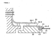
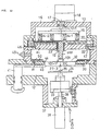
- An opening portion 32 for exposing the upper surface of the disk substrate 31 at sputtering chamber 11 is provided on the bottom wall 30 dividing the sputtering chamber 11 and the transport chamber 12.
- the disk pusher 34 is a metal disk having, at the center portion of the upper surface, a projection 36 extending through the center hole 35 of the disk substrate 31.
- the shaft 39 of the cylinder 38 moves upward and the disk pusher 34 inserts its projection 36 into the center hole 35 to push the disk substrate 31 above the susceptor portion 42.
- the upward motion is stopped when the disk substrate 31 is in contact with the concave portion 27-2 of the center mask 27.
- the disk substrate 31 is placed in the opening portion 32 provided in the bottom wall 30 of the sputtering chamber 11.
- the ring shaped outer mask 44 placed at a step portion 43 formed in the wall around the opening portion 32 of the bottom wall 30, is pushed upward to be placed on the periphery of the disk substrate 31.
- the vacuum motor 33 begins to rotate and the sputtering is carried on.
- the center mask 27 rotates together with the disk substrate 31 by " L" shaped bearing on which bearing 26 is fixed, since the projection 36 of the disk pusher 34 is inserted into the concave portion 27-2 of the center mask 27.
- the center mask 27 has not only a masking function of preventing the deposition of the sputter material on the central portion of the rotating disk substrate 31, but also has a function of stable holding of the disk substrate 31 on the disk pusher 34 by continuously applying pressure on the surface of the rotating disk substrate 31.
- an electron trap 50 composed from a pair of copper plates 50-1, 50-2 arranged to face each other with a narrow gap, is provided on the bottom wall 30 of the sputtering chamber 11.
- the target 21 is made of an insulator such as Si
- insulator material deposits on the inside wall of the sputtering chamber 11 by sputtering, resulting in prevention of the flow of electrons generated in the discharge space of the sputtering chamber 11 into the inside wall of the sputtering chamber 11 making it difficult to maintain a stable discharge.
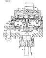
- Fig.3 is a cross section of the sputtering apparatus showing another embodiment of the invention
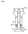
- Fig.4 is an enlarged view of the main portion of Fig.3.
- the rotation axis 27-3 of the disk substrate 31 is arranged concentrically with the center shaft 21-1 of the target 21, instead of being eccentrical.
- the funnel shaped center mask 61 having a concave portion 61-1 into which the projection 36 of the disk pusher 34 is inserted is coupled rotably through the ball bearing mechanism 62-1 with the bottom end of the cylindrical bearing 62 which is extended downward through the center hole 23 of the target 21.
- the ball bearing mechanism 62-1 is provided around the bolt 63 coupled at the hollow portion of the cylindrical bearing 62.
- the funnel shaped center mask 61 is coupled with the ball bearing mechanism 62-1 wherein the ball bearing mechanism 62-1 is stored inside the upper end hollow portion of the funnel shaped center mask 61 as is shown in Fig.4.
- the upper portion of the cylindrical bearing 62 is cooled by the cylindrical water cooling jacket 19-2 of the backing plate 20 and the center mask connected therewith is also cooled.
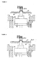
- Fig.5 is an enlarged view of the center mask portion showing further different embodiment of the invention.
- the center mask 71 comprises a cylindrical portion 71-1 extending downward through the center hole 23 of the target 21, a funnel shaped large diameter portion 71-2 provided at the lower end, a ball bearing mechanism 72 embedded rotably around the shaft column 71-3 and a ring shaped rotating disc 73 provided around the shift column 71-3 by the ball bearing mechanism 72.
- the ring shaped rotation disk 73 comprises a horizontal portion 73-1 contacting with the surface of disk substrate around the center hole 35 and a vertical portion 73-2 forming a part of the ball bearing mechanism 72.
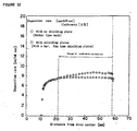
- the deposition rate distribution and refractive index of the sputtered film vary from ⁇ 3.0 to ⁇ 5.3 and ⁇ 3.7 to ⁇ 4.9, respectively.
- the growth rate distribution and the refractive index of the surface of the disk substrate by the sputtering apparatus of the invention wherein the disk substrate rotates the circumferential distribution vary from ⁇ 0.7 to ⁇ 3.5, and from ⁇ 0.3 to ⁇ 1.1, respectively , showing a remarkable decrease in fluctuation.
- the disk substrate 31 transported to the disk pusher 34 from the susceptor 42 provided on the end of the disk transport arm 40 is rotated by the vacuum motor 33 together with the center mask 91 in the situation that the projection 36 of the disk pusher 34 is fitting with the convex portion of the center mask 91 at the rise of cylinder shaft 39.
- the various shapes of the shielding plates 94-1, 94-2 fixed on the support bar 92 in this embodiment can be designed so as to make thickness uniformity uniform, by simulations or experiments.
- the center mask which does not rotate by itself and keeps stationary at a position slightly apart from the surface of the disk substrate as mentioned above, is applicable for the apparatus shown in Fig.1 or Fig.10.
Landscapes
- Chemical & Material Sciences (AREA)
- Engineering & Computer Science (AREA)
- Chemical Kinetics & Catalysis (AREA)
- Materials Engineering (AREA)
- Mechanical Engineering (AREA)
- Metallurgy (AREA)
- Organic Chemistry (AREA)
- Physics & Mathematics (AREA)
- Manufacturing & Machinery (AREA)
- Plasma & Fusion (AREA)
- Analytical Chemistry (AREA)
- Physical Vapour Deposition (AREA)
- Manufacturing Optical Record Carriers (AREA)
- Manufacturing Of Magnetic Record Carriers (AREA)
- Manufacturing Of Printed Wiring (AREA)
- Cleaning Implements For Floors, Carpets, Furniture, Walls, And The Like (AREA)
- Casting Or Compression Moulding Of Plastics Or The Like (AREA)
Claims (17)
- Appareil de pulvérisation cathodique à magnétron pour traiter un substrat unique comprenant :une chambre de pulvérisation cathodique (11) dans laquelle on prévoit un espace de décharge étanche à l'air,des moyens de génération de champ magnétique (13, 14-1, 14-2,15, 17, 18) situés au-dessus de ladite chambre de pulvérisation cathodique,une cible (21) prévue à la partie supérieure de ladite chambre de pulvérisation cathodique afin que le champ magnétique desdits moyens de génération de champ magnétique y soit appliqué,une chambre de transport de disque (12) offrant un espace étanche à l'air raccordé à ladite chambre de pulvérisation cathodique par l'intermédiaire d'une ouverture (32) formée dans une paroi inférieure (30) de ladite chambre de pulvérisation cathodique,un poussoir de disque (34) prévu à l'intérieur de ladite chambre de transport de disque pour transporter un substrat formant disque (31), sur lequel un film de pulvérisation cathodique est à former, jusqu'à la partie d'ouverture de ladite chambre de pulvérisation cathodique et pour faire tourner ledit substrat formant disque sur celui-ci,et un masque central rotatif (27, 61, 91) pour entrer en contact avec la partie centrale supérieure dudit substrat formant disque (31) et étant prévu à l'intérieur de ladite chambre de pulvérisation cathodique pour pouvoir tourner avec la rotation dudit substrat formant disque.
- Appareil de pulvérisation cathodique à magnétron pour traiter un substrat unique selon la revendication 1, ledit masque central rotatif (27, 61) étant supporté en rotation par un palier (24, 62) s'étendant à partir d'une partie centrale de ladite cible (21).
- Appareil de pulvérisation cathodique à magnétron pour traiter un substrat unique selon la revendication 2, une chemise de refroidissement par eau cylindrique (19) étant prévue qui s'étend à travers la partie centrale de ladite cible, ledit palier (24) étant raccordé à ladite chemise de refroidissement par eau.
- Appareil de pulvérisation cathodique à magnétron pour traiter un substrat unique selon la revendication 1, l'arbre de rotation (39) dudit poussoir de disque (34) étant agencé de manière excentrique par rapport au centre de ladite cible (21).
- Appareil de pulvérisation cathodique à magnétron pour traiter un substrat unique selon la revendication 1, ledit masque central (27) étant supporté en rotation par un palier de rotation (24) ayant une section transversale en forme de « L » qui s'étend à partir de la partie centrale de ladite cible (21).
- Appareil de pulvérisation cathodique à magnétron pour traiter un substrat unique selon revendications 3 et 5, ledit palier en forme de « L » (24) étant raccordé à la chemise de refroidissement par eau cylindrique (19) par des boulons de blocage (25).
- Appareil de pulvérisation cathodique à magnétron pour traiter un substrat unique selon la revendication 1, ledit masque central rotatif (91) étant supporté de manière rotative au niveau de la partie centrale d'une barre de support (92) enjambant l'ouverture (32) formée dans la paroi inférieure (30) de ladite chambre de pulvérisation cathodique, ladite barre de support étant équipée de plaques de protection (94-1, 94-2) pour empêcher le matériau de pulvérisation cathodique provenant de ladite cible d'atteindre la surface dudit substrat.
- Appareil de pulvérisation cathodique à magnétron pour traiter un substrat unique selon la revendication 7, lesdites plaques de protection (94-1, 94-2) étant prévues sur au moins un côté entre les deux extrémités et la partie centrale de ladite barre de support (92), et ayant une telle forme que la largeur desdites plaques de protection augmente progressivement, et ensuite diminue progressivement, le long de la direction longitudinale le long de ladite barre de support (92).
- Appareil de pulvérisation cathodique à magnétron pour traiter un substrat unique selon la revendication 8, ladite barre de support (92) étant équipée d'une chemise de refroidissement (95).
- Appareil de pulvérisation cathodique à magnétron pour traiter un substrat unique selon la revendication 1, un masque externe de forme annulaire (44) étant prévu sur la périphérie de l'ouverture (32) de ladite chambre de pulvérisation cathodique et lorsque ledit poussoir de disque (34) transporte le substrat de disque (31) vers l'ouverture de ladite chambre de pulvérisation cathodique, ledit masque externe de forme annulaire est placé sur la périphérie externe dudit substrat de disque (31) et est entraîné en rotation avec la rotation du substrat de disque.
- Appareil de pulvérisation cathodique à magnétron pour traiter un substrat unique selon la revendication 10, ledit masque externe de forme annulaire (44) étant situé sur une marche (43) prévue au niveau de la périphérie de l'ouverture (32) de ladite chambre de pulvérisation cathodique (11).
- Appareil de pulvérisation cathodique à magnétron pour traiter un substrat unique, comprenant :une chambre de pulvérisation cathodique (11) dans laquelle on prévoit un espace de décharge étanche à l'air,des moyens de génération de champ magnétique (13, 14-1,14-2, 15, 17, 18) pour générer un champ magnétique à l'intérieur de ladite chambre de pulvérisation cathodique,une cible (21) agencée à l'intérieur de ladite chambre de pulvérisation cathodique de sorte que l'on peut appliquer le champ magnétique par lesdits moyens de génération de champ magnétique,une chambre de transport de disque (12) pour offrir un espace étanche à l'air raccordé à ladite chambre de pulvérisation cathodique par l'intermédiaire d'une ouverture (32) formée dans une paroi inférieure (30) de ladite chambre de pulvérisation cathodique (11),un poussoir de disque (34) prévu dans ladite chambre de transport de disque pour supporter un substrat en forme de disque (31), pour le transport jusqu'à l'ouverture de ladite chambre de pulvérisation cathodique (11) et pour faire tourner ledit substrat en forme de disque dans un plan,et un masque central (27, 91, 101) agencé de manière fixe en ménageant un espace avec la partie centrale de la surface du substrat de disque maintenu sur ledit poussoir de disque.
- Appareil de pulvérisation cathodique à magnétron pour traiter un substrat unique selon la revendication 12, ledit masque central étant fixé sur un support cylindrique (27-3, 102) s'étendant à partir d'une partie centrale de ladite cible (21).
- Appareil de pulvérisation cathodique à magnétron pour traiter un substrat unique selon la revendication 13, l'arbre de rotation (39) dudit poussoir de disque étant agencé de manière excentrique par rapport au centre de ladite cible.
- Appareil de pulvérisation cathodique à magnétron pour traiter un substrat unique selon la revendication 12, ledit masque central étant supporté sur la partie centrale d'une barre de support (92) enjambant le pont sur l'ouverture (32) formée dans la paroi inférieure de ladite chambre de pulvérisation cathodique, et ladite barre de support étant équipée avec de plaques de protection (94-1, 94-2) pour empêcher le matériau de pulvérisation cathodique provenant de ladite cible d'atteindre la surface dudit substrat de disque.
- Appareil de pulvérisation cathodique à magnétron pour traiter un substrat unique selon la revendication 15, lesdites plaques de protection (94-1, 94-2) étant prévues au moins en partie entre les deux extrémités et la partie centrale de ladite barre de support, et les formes desdites plaques de protection étant telles que leur largeur augmente progressivement et diminue ensuite le long de la direction longitudinale de ladite barre de support (92).
- Appareil de pulvérisation cathodique à magnétron pour traiter un substrat unique selon la revendication 16, ladite barre de support étant équipée d'une chemise de refroidissement (95).
Applications Claiming Priority (3)
| Application Number | Priority Date | Filing Date | Title |
|---|---|---|---|
| JP19353097 | 1997-07-18 | ||
| JP09193530A JP3096258B2 (ja) | 1997-07-18 | 1997-07-18 | 毎葉式マグネトロンスパッタ装置 |
| PCT/JP1998/003236 WO1999004058A1 (fr) | 1997-07-18 | 1998-07-17 | Dispositif de pulverisation cathodique a magnetron a feuille |
Publications (3)
| Publication Number | Publication Date |
|---|---|
| EP0933444A1 EP0933444A1 (fr) | 1999-08-04 |
| EP0933444A4 EP0933444A4 (fr) | 2004-05-26 |
| EP0933444B1 true EP0933444B1 (fr) | 2008-01-02 |
Family
ID=16309613
Family Applications (1)
| Application Number | Title | Priority Date | Filing Date |
|---|---|---|---|
| EP98932581A Expired - Lifetime EP0933444B1 (fr) | 1997-07-18 | 1998-07-17 | Dispositif de pulverisation cathodique a magnetron a feuille |
Country Status (9)
| Country | Link |
|---|---|
| US (1) | US6083364A (fr) |
| EP (1) | EP0933444B1 (fr) |
| JP (1) | JP3096258B2 (fr) |
| KR (1) | KR100378752B1 (fr) |
| CN (1) | CN1173071C (fr) |
| AT (1) | ATE382721T1 (fr) |
| DE (1) | DE69838937T2 (fr) |
| TW (1) | TW520403B (fr) |
| WO (1) | WO1999004058A1 (fr) |
Families Citing this family (12)
| Publication number | Priority date | Publication date | Assignee | Title |
|---|---|---|---|---|
| EP1250471A1 (fr) * | 2000-01-18 | 2002-10-23 | Unaxis Balzers Aktiengesellschaft | Chambre a pulverisation cathodique et chambre de transport a vide, et installations de traitement du vide comportant des chambres de ce type |
| US6887356B2 (en) * | 2000-11-27 | 2005-05-03 | Cabot Corporation | Hollow cathode target and methods of making same |
| US6740209B2 (en) * | 2001-07-27 | 2004-05-25 | Anelva Corporation | Multilayer film deposition apparatus, and method and apparatus for manufacturing perpendicular-magnetic-recording media |
| US6776887B2 (en) * | 2002-03-29 | 2004-08-17 | Imation Corp. | Method and apparatus for thin film center shielding |
| JP2003293131A (ja) * | 2002-04-04 | 2003-10-15 | Tdk Corp | スパッタリング装置、スパッタリングによる薄膜形成方法および当該装置を用いたディスク状記録媒体の製造方法 |
| TWI396766B (zh) * | 2005-03-11 | 2013-05-21 | 索雷拉斯先進塗料公司 | 用於支承可旋轉濺射目標的扁平端塊 |
| JP4412293B2 (ja) * | 2006-02-08 | 2010-02-10 | セイコーエプソン株式会社 | スパッタ装置 |
| CN110050325B (zh) * | 2016-12-19 | 2021-11-09 | 应用材料公司 | 溅射沉积源、具有该溅射沉积源的溅射沉积设备以及将层沉积于基板上的方法 |
| CN110997974A (zh) * | 2017-08-21 | 2020-04-10 | 堺显示器制品株式会社 | 蒸镀装置、蒸镀方法以及有机el显示装置的制造方法 |
| JP6514381B2 (ja) * | 2018-02-27 | 2019-05-15 | 堺ディスプレイプロダクト株式会社 | 蒸着装置、蒸着方法及び有機el表示装置の製造方法 |
| JP7326106B2 (ja) * | 2019-10-16 | 2023-08-15 | 株式会社アルバック | スパッタリング装置 |
| CN114166590B (zh) * | 2021-11-15 | 2022-07-15 | 哈尔滨工业大学(威海) | 一种用于介观尺度试样力学性能测试的磁控溅射设备 |
Family Cites Families (13)
| Publication number | Priority date | Publication date | Assignee | Title |
|---|---|---|---|---|
| JPS61213368A (ja) * | 1985-03-20 | 1986-09-22 | Hitachi Maxell Ltd | 真空成膜装置 |
| JPH01294242A (ja) * | 1988-02-22 | 1989-11-28 | Seiko Epson Corp | 光記録媒体の製造方法 |
| JPH062136A (ja) * | 1992-06-23 | 1994-01-11 | Toshiba Corp | 枚葉式成膜装置 |
| JPH0734927Y2 (ja) * | 1992-09-02 | 1995-08-09 | 中外炉工業株式会社 | マグネットチャック式基板ホルダー |
| EP0663019B1 (fr) * | 1992-09-30 | 1998-12-02 | Advanced Energy Industries, Inc. | Systeme de revetement de film mince topographiquement precis |
| JPH06116721A (ja) * | 1992-10-06 | 1994-04-26 | Nec Yamaguchi Ltd | スパッタリング装置 |
| DE4302851A1 (de) * | 1993-02-02 | 1994-08-04 | Leybold Ag | Vorrichtung zum Anbringen und/oder Entfernen einer Maske an einem Substrat |
| JPH0757233A (ja) * | 1993-08-19 | 1995-03-03 | Hitachi Ltd | 磁気記録媒体 |
| JP3398452B2 (ja) * | 1994-01-19 | 2003-04-21 | 株式会社ソニー・ディスクテクノロジー | スパッタリング装置 |
| US5800687A (en) * | 1996-04-13 | 1998-09-01 | Singulus Technologies Gmbh | Device for masking or covering substrates |
| US5863399A (en) * | 1996-04-13 | 1999-01-26 | Singulus Technologies Gmbh | Device for cathode sputtering |
| JPH09310167A (ja) * | 1996-05-21 | 1997-12-02 | Toshiba Corp | 枚葉式マグネトロンスパッタリング装置 |
| JPH10121225A (ja) * | 1996-10-09 | 1998-05-12 | Shibaura Eng Works Co Ltd | マスクの着脱装置 |
-
1997
- 1997-07-18 JP JP09193530A patent/JP3096258B2/ja not_active Expired - Fee Related
-
1998
- 1998-07-17 AT AT98932581T patent/ATE382721T1/de not_active IP Right Cessation
- 1998-07-17 KR KR10-1999-7002345A patent/KR100378752B1/ko not_active Expired - Fee Related
- 1998-07-17 WO PCT/JP1998/003236 patent/WO1999004058A1/fr not_active Ceased
- 1998-07-17 DE DE69838937T patent/DE69838937T2/de not_active Expired - Fee Related
- 1998-07-17 CN CNB98800979XA patent/CN1173071C/zh not_active Expired - Fee Related
- 1998-07-17 EP EP98932581A patent/EP0933444B1/fr not_active Expired - Lifetime
- 1998-07-17 US US09/269,051 patent/US6083364A/en not_active Expired - Fee Related
- 1998-07-18 TW TW087111740A patent/TW520403B/zh not_active IP Right Cessation
Also Published As
| Publication number | Publication date |
|---|---|
| EP0933444A4 (fr) | 2004-05-26 |
| KR20000068592A (ko) | 2000-11-25 |
| CN1234838A (zh) | 1999-11-10 |
| US6083364A (en) | 2000-07-04 |
| CN1173071C (zh) | 2004-10-27 |
| DE69838937T2 (de) | 2008-12-24 |
| DE69838937D1 (de) | 2008-02-14 |
| JP3096258B2 (ja) | 2000-10-10 |
| KR100378752B1 (ko) | 2003-04-07 |
| ATE382721T1 (de) | 2008-01-15 |
| TW520403B (en) | 2003-02-11 |
| WO1999004058A1 (fr) | 1999-01-28 |
| JPH1136075A (ja) | 1999-02-09 |
| EP0933444A1 (fr) | 1999-08-04 |
Similar Documents
| Publication | Publication Date | Title |
|---|---|---|
| EP0933444B1 (fr) | Dispositif de pulverisation cathodique a magnetron a feuille | |
| US5464518A (en) | Cylindrical magnetron shield structure | |
| US5772858A (en) | Method and apparatus for cleaning a target in a sputtering source | |
| JP2000144399A (ja) | スパッタリング装置 | |
| JPH05209266A (ja) | 分布磁界を有するマグネトロン・スパッタ・ガン・ターゲット・アセンブリ | |
| KR20010043955A (ko) | 경사진 스퍼터링 타겟 | |
| JPS5844742B2 (ja) | スパツタリング装置 | |
| KR100532805B1 (ko) | 기판상의 박막 증착 장치 및 방법 | |
| JPH09228038A (ja) | 中空のターゲットを備えた、陰極スパッタによりサブストレートを被覆するための装置 | |
| US6743342B2 (en) | Sputtering target with a partially enclosed vault | |
| US20050178653A1 (en) | Method for elimination of sputtering into the backing plate of a target/backing plate assembly | |
| JPH02285069A (ja) | スパッタ装置 | |
| US6159350A (en) | Magnetron sputtering apparatus and mask | |
| US5328582A (en) | Off-axis magnetron sputter deposition of mirrors | |
| JPH09111450A (ja) | マグネトロン型スパッタリング装置 | |
| JP2002133650A (ja) | 磁気記録ディスク用成膜装置 | |
| JP4274452B2 (ja) | スパッタ源及び成膜装置 | |
| JP2000064044A (ja) | 枚葉式マグネトロンスパッタ装置 | |
| EP1496135A1 (fr) | Dispositif de pulverisation cathodique, procede de formation de couche mince par pulverisation cathodique et procede de fabrication de support d'enregistrement en forme de disque au moyen de ce dispositif | |
| JP4378017B2 (ja) | 光ディスク用スパッタ装置 | |
| JPH07331434A (ja) | マグネトロンスパッタリング装置 | |
| JP2646260B2 (ja) | スパッタ装置 | |
| JPH1064723A (ja) | マグネトロンスパッタ用磁石 | |
| JPS61235561A (ja) | マグネトロンスパツタ装置 | |
| JPH03271369A (ja) | スパッタ装置 |
Legal Events
| Date | Code | Title | Description |
|---|---|---|---|
| PUAI | Public reference made under article 153(3) epc to a published international application that has entered the european phase |
Free format text: ORIGINAL CODE: 0009012 |
|
| AK | Designated contracting states |
Kind code of ref document: A1 Designated state(s): AT DE FR GB IE |
|
| 17P | Request for examination filed |
Effective date: 19990707 |
|
| A4 | Supplementary search report drawn up and despatched |
Effective date: 20040413 |
|
| RIC1 | Information provided on ipc code assigned before grant |
Ipc: 7G 11B 7/26 B Ipc: 7C 23C 14/50 B Ipc: 7C 23C 14/35 B Ipc: 7C 23C 14/34 B Ipc: 7H 01J 37/34 B Ipc: 7C 23C 14/04 B Ipc: 7C 23C 14/56 A |
|
| GRAP | Despatch of communication of intention to grant a patent |
Free format text: ORIGINAL CODE: EPIDOSNIGR1 |
|
| GRAS | Grant fee paid |
Free format text: ORIGINAL CODE: EPIDOSNIGR3 |
|
| RAP1 | Party data changed (applicant data changed or rights of an application transferred) |
Owner name: SHIBAURA MECHATRONICS CORPORATION |
|
| GRAA | (expected) grant |
Free format text: ORIGINAL CODE: 0009210 |
|
| AK | Designated contracting states |
Kind code of ref document: B1 Designated state(s): AT DE FR GB IE |
|
| REG | Reference to a national code |
Ref country code: GB Ref legal event code: FG4D |
|
| REG | Reference to a national code |
Ref country code: IE Ref legal event code: FG4D |
|
| REF | Corresponds to: |
Ref document number: 69838937 Country of ref document: DE Date of ref document: 20080214 Kind code of ref document: P |
|
| ET | Fr: translation filed | ||
| PLBE | No opposition filed within time limit |
Free format text: ORIGINAL CODE: 0009261 |
|
| STAA | Information on the status of an ep patent application or granted ep patent |
Free format text: STATUS: NO OPPOSITION FILED WITHIN TIME LIMIT |
|
| 26N | No opposition filed |
Effective date: 20081003 |
|
| GBPC | Gb: european patent ceased through non-payment of renewal fee |
Effective date: 20080717 |
|
| PG25 | Lapsed in a contracting state [announced via postgrant information from national office to epo] |
Ref country code: DE Free format text: LAPSE BECAUSE OF NON-PAYMENT OF DUE FEES Effective date: 20090203 |
|
| REG | Reference to a national code |
Ref country code: FR Ref legal event code: ST Effective date: 20090331 |
|
| PG25 | Lapsed in a contracting state [announced via postgrant information from national office to epo] |
Ref country code: GB Free format text: LAPSE BECAUSE OF NON-PAYMENT OF DUE FEES Effective date: 20080717 |
|
| PG25 | Lapsed in a contracting state [announced via postgrant information from national office to epo] |
Ref country code: IE Free format text: LAPSE BECAUSE OF NON-PAYMENT OF DUE FEES Effective date: 20080717 |
|
| PG25 | Lapsed in a contracting state [announced via postgrant information from national office to epo] |
Ref country code: FR Free format text: LAPSE BECAUSE OF NON-PAYMENT OF DUE FEES Effective date: 20080731 |
|
| PG25 | Lapsed in a contracting state [announced via postgrant information from national office to epo] |
Ref country code: AT Free format text: LAPSE BECAUSE OF NON-PAYMENT OF DUE FEES Effective date: 20080717 |