EP0950858A2 - Bougie à incandescence - Google Patents
Bougie à incandescence Download PDFInfo
- Publication number
- EP0950858A2 EP0950858A2 EP99302933A EP99302933A EP0950858A2 EP 0950858 A2 EP0950858 A2 EP 0950858A2 EP 99302933 A EP99302933 A EP 99302933A EP 99302933 A EP99302933 A EP 99302933A EP 0950858 A2 EP0950858 A2 EP 0950858A2
- Authority
- EP
- European Patent Office
- Prior art keywords
- sheath tube
- coil
- glow plug
- heating coil
- heating
- Prior art date
- Legal status (The legal status is an assumption and is not a legal conclusion. Google has not performed a legal analysis and makes no representation as to the accuracy of the status listed.)
- Granted
Links
- 238000010438 heat treatment Methods 0.000 claims abstract description 139
- 239000002184 metal Substances 0.000 claims abstract description 50
- 229910052751 metal Inorganic materials 0.000 claims abstract description 50
- 230000000630 rising effect Effects 0.000 claims abstract description 49
- 229920006395 saturated elastomer Polymers 0.000 claims abstract description 15
- 229910045601 alloy Inorganic materials 0.000 claims description 15
- 239000000956 alloy Substances 0.000 claims description 15
- XEEYBQQBJWHFJM-UHFFFAOYSA-N Iron Chemical compound [Fe] XEEYBQQBJWHFJM-UHFFFAOYSA-N 0.000 claims description 14
- 239000011295 pitch Substances 0.000 claims description 13
- 229910052742 iron Inorganic materials 0.000 claims description 6
- 238000005219 brazing Methods 0.000 claims description 5
- 238000003466 welding Methods 0.000 claims description 4
- 238000004804 winding Methods 0.000 claims description 4
- 229910001220 stainless steel Inorganic materials 0.000 claims description 3
- 239000010935 stainless steel Substances 0.000 claims description 3
- 239000000463 material Substances 0.000 description 23
- 238000005452 bending Methods 0.000 description 11
- 229910017060 Fe Cr Inorganic materials 0.000 description 10
- 229910002544 Fe-Cr Inorganic materials 0.000 description 10
- UPHIPHFJVNKLMR-UHFFFAOYSA-N chromium iron Chemical compound [Cr].[Fe] UPHIPHFJVNKLMR-UHFFFAOYSA-N 0.000 description 10
- CPLXHLVBOLITMK-UHFFFAOYSA-N Magnesium oxide Chemical compound [Mg]=O CPLXHLVBOLITMK-UHFFFAOYSA-N 0.000 description 8
- 238000000034 method Methods 0.000 description 8
- 229910020598 Co Fe Inorganic materials 0.000 description 7
- 229910002519 Co-Fe Inorganic materials 0.000 description 7
- 238000005304 joining Methods 0.000 description 6
- 230000008569 process Effects 0.000 description 6
- 238000012360 testing method Methods 0.000 description 6
- PXHVJJICTQNCMI-UHFFFAOYSA-N nickel Substances [Ni] PXHVJJICTQNCMI-UHFFFAOYSA-N 0.000 description 5
- 239000000843 powder Substances 0.000 description 5
- 230000009467 reduction Effects 0.000 description 5
- 230000035939 shock Effects 0.000 description 5
- 238000002788 crimping Methods 0.000 description 4
- 230000000694 effects Effects 0.000 description 4
- 239000000395 magnesium oxide Substances 0.000 description 4
- 229910001313 Cobalt-iron alloy Inorganic materials 0.000 description 3
- 238000002485 combustion reaction Methods 0.000 description 3
- 238000013461 design Methods 0.000 description 3
- 239000000203 mixture Substances 0.000 description 3
- 230000005855 radiation Effects 0.000 description 3
- 229910000975 Carbon steel Inorganic materials 0.000 description 2
- VYZAMTAEIAYCRO-UHFFFAOYSA-N Chromium Chemical compound [Cr] VYZAMTAEIAYCRO-UHFFFAOYSA-N 0.000 description 2
- 229910000963 austenitic stainless steel Inorganic materials 0.000 description 2
- 239000010962 carbon steel Substances 0.000 description 2
- 229920001971 elastomer Polymers 0.000 description 2
- 238000011156 evaluation Methods 0.000 description 2
- 238000005242 forging Methods 0.000 description 2
- 229910001026 inconel Inorganic materials 0.000 description 2
- 239000011810 insulating material Substances 0.000 description 2
- 238000003754 machining Methods 0.000 description 2
- 238000004519 manufacturing process Methods 0.000 description 2
- 238000005259 measurement Methods 0.000 description 2
- 238000012986 modification Methods 0.000 description 2
- 230000004048 modification Effects 0.000 description 2
- 238000005549 size reduction Methods 0.000 description 2
- 238000012546 transfer Methods 0.000 description 2
- 229920001342 Bakelite® Polymers 0.000 description 1
- 229910000760 Hardened steel Inorganic materials 0.000 description 1
- 239000004677 Nylon Substances 0.000 description 1
- 229910000831 Steel Inorganic materials 0.000 description 1
- 239000004637 bakelite Substances 0.000 description 1
- 230000008901 benefit Effects 0.000 description 1
- 230000015572 biosynthetic process Effects 0.000 description 1
- 230000008859 change Effects 0.000 description 1
- 229910017052 cobalt Inorganic materials 0.000 description 1
- 239000010941 cobalt Substances 0.000 description 1
- GUTLYIVDDKVIGB-UHFFFAOYSA-N cobalt atom Chemical compound [Co] GUTLYIVDDKVIGB-UHFFFAOYSA-N 0.000 description 1
- 230000000052 comparative effect Effects 0.000 description 1
- 230000001276 controlling effect Effects 0.000 description 1
- 230000007797 corrosion Effects 0.000 description 1
- 238000005260 corrosion Methods 0.000 description 1
- 238000010586 diagram Methods 0.000 description 1
- 230000001747 exhibiting effect Effects 0.000 description 1
- 238000002347 injection Methods 0.000 description 1
- 239000007924 injection Substances 0.000 description 1
- 238000011835 investigation Methods 0.000 description 1
- 238000002844 melting Methods 0.000 description 1
- 230000008018 melting Effects 0.000 description 1
- 229910052759 nickel Inorganic materials 0.000 description 1
- 229920001778 nylon Polymers 0.000 description 1
- 230000003647 oxidation Effects 0.000 description 1
- 238000007254 oxidation reaction Methods 0.000 description 1
- 238000007747 plating Methods 0.000 description 1
- 229910000753 refractory alloy Inorganic materials 0.000 description 1
- 230000001105 regulatory effect Effects 0.000 description 1
- 230000002787 reinforcement Effects 0.000 description 1
- 229920005989 resin Polymers 0.000 description 1
- 239000011347 resin Substances 0.000 description 1
- 238000000926 separation method Methods 0.000 description 1
- 229920002379 silicone rubber Polymers 0.000 description 1
- 239000010959 steel Substances 0.000 description 1
- XLYOFNOQVPJJNP-UHFFFAOYSA-N water Substances O XLYOFNOQVPJJNP-UHFFFAOYSA-N 0.000 description 1
- 238000009736 wetting Methods 0.000 description 1
Images





Classifications
-
- F—MECHANICAL ENGINEERING; LIGHTING; HEATING; WEAPONS; BLASTING
- F23—COMBUSTION APPARATUS; COMBUSTION PROCESSES
- F23Q—IGNITION; EXTINGUISHING-DEVICES
- F23Q7/00—Incandescent ignition; Igniters using electrically-produced heat, e.g. lighters for cigarettes; Electrically-heated glowing plugs
- F23Q7/001—Glowing plugs for internal-combustion engines
-
- H—ELECTRICITY
- H05—ELECTRIC TECHNIQUES NOT OTHERWISE PROVIDED FOR
- H05B—ELECTRIC HEATING; ELECTRIC LIGHT SOURCES NOT OTHERWISE PROVIDED FOR; CIRCUIT ARRANGEMENTS FOR ELECTRIC LIGHT SOURCES, IN GENERAL
- H05B3/00—Ohmic-resistance heating
- H05B3/40—Heating elements having the shape of rods or tubes
- H05B3/42—Heating elements having the shape of rods or tubes non-flexible
- H05B3/44—Heating elements having the shape of rods or tubes non-flexible heating conductor arranged within rods or tubes of insulating material
Definitions
- the present invention relates to a glow plug for use, for example, to pre-heat a diesel engine.
- the glow plug incorporates a sheath heater having a sheath tube that is made of heat resisting metal.
- a heating coil constituted by a resistance heating wire is enclosed together with insulating powder.
- a main metal shell is joined to the sheath heater.
- a thread portion formed around the outer surface of the main metal shell is used to join the glow plug to the engine block of a diesel engine such that the heating portion formed at the leading end of the sheath heater is positioned in the combustion chamber.
- the temperature rising performance of the heater is usually required to have a so-called quick heating characteristic with which a saturated temperature can quickly be realized in order to improve the starting characteristic of the engine.
- the glow plug incorporates a control coil made of a material having a positive temperature coefficient of resistance.
- the control coil is, in the sheath tube, disposed in series with the heating coil so as to improve the quick heating characteristic and prevent excessive rise in the temperature of the coil.
- the control coil has a low temperature in the initial stage of the energization. Because the electric resistance is low, a relatively large electric current is passed through the heating coil, thereby causing the heating coil to be heated quickly.
- the control coil When the temperature of the heating coil is raised, the control coil is heated with the heat of the heating coil so that the electric resistance of the control coil is raised. As a result, the electric current which is supplied to the heating coil is lowered. As a result, the temperature rising characteristic of the heater takes the form that the temperature is quickly raised in the initial stage of the energization. Then, the operation of the control coil reduces the supplied current so that the temperature is saturated.
- a temperature rising characteristic for the glow plug is a characteristic indicated such that ⁇ is equal to 4.38. That is, the preferred characteristic is such that the temperature is monotonically raised in the initial stage of the energization after which the temperature is saturated without formation of a peak.
- the inventors of the present invention have found that the above-mentioned temperature rising characteristic is not necessarily a preferred characteristic for the glow plug of a diesel engine mounted on a vehicle.
- a battery is employed to serve as a power source of the glow plug of a vehicle or the like.
- the glow plug is not always applied with a predetermined voltage (for example, 12 V) of the battery.
- a superimposed voltage applied from the alternator or the like is added to the voltage of the battery. Therefore, a voltage higher (for example, 14 V or lower) than the voltage of the battery is usually applied. If the raised voltage is applied as described above, the temperature rising characteristic of the heater raises a problem in that the temperature of the heater is raised excessively because the saturated temperature is raised in proportion to the applied voltage level.
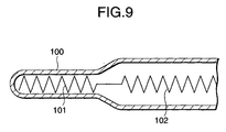
- available glow plugs have a structure as shown in Fig. 9 formed such that a portion of a sheath tube 100 for accommodating a control coil 102 has a diameter larger than that of a portion of the sheath tube 100 for accommodating a heating coil 101 so as to enlarge the thermal capacity of the portion.
- rapid rise in the temperature of the control coil 102 is prevented to realize the above-mentioned excess-rise-preventive temperature rising characteristic (refer to, for example, Unexamined Japanese Patent Publication (kokai) No. 3-99122).
- the outer diameter of the projection of the sheath tube over the main metal shell is reduced to be smaller than 5 mm. If the outer diameter of the portion of the sheath tube 100 for accommodating the enlarged control coil 102 is made to be smaller than 5 mm, the portion for accommodating the heating coil 101 is made to be smaller than the value. As a result, the mechanical strength of the portion becomes insufficient. When a shock is exerted, the portion easily broken. What is worse, the outer diameter of the heating coil is too small to obtain a satisfactory increased heating performance.
- the sheath tube has a simple shape for the purpose of preventing the above-mentioned problems. That is, it is preferable that the shape is formed such that the portions for accommodating the heating coil and the control coil have similar outer diameters.
- the simple shape of projection of the sheath tube is as well advantageous to widen the design freedom of the engine head on which the glow plug is mounted.
- It is an object of the present invention is to provide a glow plug incorporating a sheath heater having a representative excess-rise-preventive temperature rising characteristic, in which the outer diameter of the sheath tube can be reduced to be smaller than 5 mm.
- a glow plug comprises: a sheath tube having a closed leading end; a cylindrical main metal shell disposed on the outside of said sheath tube, said sheath tube having a projecting portion in a leading end of said sheath tube projecting over said main metal shell; and a plurality of resistance-wire coils disposed in the axial direction in said sheath tube, said resistance-wire coils including a heating coil and a control coil in a portion of said sheath tube projecting over said main metal shell, said heating coil being disposed adjacent to the leading end of the projecting portion, said control coil being connected to the rear end of said heating coil in series and arranged to be heated by said heating coil to raise electric resistance so as to control supply of electric power to said heating coil; wherein said projecting portion of said sheath tube has substantially the same outer diameter in the axial direction and the outer diameter is in the range of 3.0 mm to 4.4 mm so that a temperature rising characteristic at the surface of the leading end of said sheath tube is made to
- a glow plug according to the present invention has a sheath tube, a cylindrical main metal shell, and a plurality of resistance-wire coils.
- the sheath tube has a closed leading end.
- the cylindrical main metal shell disposed on the outside of the sheath tube in a state in which the leading end of the sheath tube projects over the main metal shell.
- the plurality of resistance-wire coils disposed in the axial direction in the sheath tube.
- the resistance-wire coils include a heating coil and a control coil in a portion of the sheath tube projecting over the main metal shell.
- the heating coil is disposed adjacent to the leading end of the projecting portion.
- the control coil is connected to the rear end of the heating coil in series and arranged to be heated by the heating coil to raise electric resistance so as to control supply of electric power to the heating coil.
- the projecting portion of the sheath tube has substantially the same outer diameter in the axial direction.
- the outer diameter of the projecting portion is in the range of 3.0 mm to 4.4 mm so that a temperature rising characteristic at the surface of the leading end of the sheath tube is made to have a peak temperature TP in an initial stage of energization and made to be saturated at a temperature not higher than the peak temperature TP.
- a satisfactory excess-rise-preventive temperature rising characteristic that is, a temperature rising characteristic can be realized which has a peak temperature TP in the initial stage of energization and the temperature is saturated at a level not higher than the peak temperature TP.
- the present invention is established.
- the size of the portion of the projection of the sheath tube for accommodating the heating coil is made to be substantially the same as the size of the portion for accommodating the control coil. That is, the diameter is not reduced. As a result, satisfactory mechanical strength of the portion can be realized. Even if a shock is exerted, breakage does not easily take place. In addition, also a sufficiently large outer diameter of the heating coil can be maintained because the diameter is not reduced. Therefore, satisfactory heating performance can be obtained. Since the shape of the projection of the sheath tube is simplified, the design freedom of the engine block, to which the glow plug is mounted, can be widened advantageously.
- the outer diameter of the sheath tube is smaller than 3.0 mm, the outer diameter of the heating coil is reduced excessively to obtain a required heating performance. If the outer diameter is larger than 4.4 mm, the required excess-rise-preventive temperature rising characteristic cannot be realized. It is preferable that the outer diameter is 3.5 mm to 4.0 mm.
- the reason why the reduction in the outer diameter of the sheath tube to be smaller than 4.4 mm realizes the satisfactory excess-rise-preventive temperature rising characteristic will now be described.
- the diameter of the sheath tube is reduced as described above, heat radiation from the surface of the sheath tube is enhanced. As a result, heat transfer from the heating coil to the control coil is adequately prevented. Thus, even if the distance between the two coils is somewhat shortened, excessively rapid heating of the control coil can be prevented. Therefore, a stable control of energization can easily be performed.
- the projection of the sheath tube may be formed into a cylindrical shape having substantially constant outer diameters (if the leading end of the tube is rounded, the structure is formed such that the constant outer diameter is realized except for the rounded portion).
- the control coil may directly be connected to the rear end of the heating coil at a position apart from the rear end for a gap larger than each of pitches of winding of a wire for forming the heating coil.
- the length of the gap is adjusted to 0.8 mm to 3 mm. If the size of the gap between the coils is larger than 3 mm, the heating coil cannot smoothly heat the control coil. Thus, excess heating of the heating coil easily takes place. If the size of the gap between the coils is smaller than 0.8 mm, the level of the resistance of the control coil is rapidly raised. Thus, the quick heating characteristic cannot be maintained. What is worse, the saturated temperature is lowered excessively to obtain satisfactory heating performance.
- the gap between the coils is defined as the distance in the axial direction of the coil between a position shifted along the heating coil from the junction between the heating coil and the control coil for a distance corresponding to half winding and a position similarly shifted toward the control coil for a distance corresponding to half winding.
- the size of the gap is smaller than the size of the gap (about 5 mm as shown in Fig. 7) which is required for the glow plug disclosed in Unexamined Japanese Patent Publication (kokai) No. 59-60125 and incorporating a sheath tube having an outer diameter of 5 mm to obtain the excess-rise-preventive temperature rising characteristic. It is shown that enhancement of the heat radiation from the surface of the tube caused by the reduction in the diameter of the sheath tube prevents heat transfer from the heating coil to the control coil.
- the glow plug according to the present invention and having the sheath tube which has a small diameter to somewhat shorten the distance between the two coils as compared with the conventional glow plug having a large diameter when a satisfactory excess-rise-preventive temperature rising characteristic is obtained.
- the length of the gap between the coils is 1 mm to 2 mm.
- the peak temperature TP is 900°C to l150°C. If the peak temperature TP is lower than 900°C, there is apprehension that heating becomes insufficient to satisfactorily perform previous heating of the engine. If the peak temperature TP is higher than l150°C, heating is performed excessively. In this case, there is apprehension that the lifetime of the heating coil is shortened. It is preferable that the peak temperature TP is 950°C to 1050°C.
- the difference TP - TS between the peak temperature TP and temperature TS realized 60 seconds after the energization is started is 50°C to 200°C when the temperature rising characteristic is measured with an applied voltage of 11 V at room temperature. If the TP - TS is lower than 50°C, the heater is excessively heated when the applied voltage is raised. If TP - TS is higher than 200°C, the saturated temperature is lowered excessively. Thus, required heating performance cannot be obtained. It is preferable that TP - TS is 80°C to 150°C.
- the glow plug according to the present invention that the peak temperature TP is 800°C or higher and energizing time t800 required for the temperature to be raised to 800°C is 8 seconds or shorter, more preferably, 5 seconds or shorter, when the temperature rising characteristic is measured with an applied voltage of 11 V at room temperature.
- thickness t of the projection of the sheath tube over the main metal shell is 0.3 mm to 0.75 mm and the value of t/D1 is 0.08 to 0.2 on an assumption that the outer diameter is D1. If the thickness t is smaller than 0.3 mm, the strength of the sheath tube becomes insufficient. If a shock is exerted owning to drop or the like which has occurring at a joining operation, the heater is easily broken. Since the outer diameter of the sheath tube is limited to be 4.4 mm or smaller in the present invention, the inner diameter of the sheath tube is made to be too small if the thickness t is larger than 0.75 mm.
- the thickness t satisfies a range from 0.45 mm to 0.6 mm.
- the difference CG (D2 - d1)/2 between the two radii satisfies a range from 0.1 mm to 0.8 mm. If CG is shorter than 0.1 mm, short circuit easily occurs between the inner surface of the sheath tube and the heating coil and between the inner surface and the control coil. What is worse, the heating performance sometimes deteriorates.
- CG is longer than 0.8 mm, a process for enclosing the heating coil and the control coil together with an insulating material (for example, magnesia powder) to perform a forging process so as to reduce the diameter easily encounters meander of the coil in the sheath tube. In the case, short circuit similarly easily occurs. Therefore, it is preferable that the value of CG satisfies a range from 0.2 mm to 0.6 mm.
- the outer diameter d1 of each of the heating coil and the control coil is 1.5 mm to 3.0 mm. If the outer diameter d1 is smaller than 1.5 mm, a required heating performance cannot sometimes be obtained. If the outer diameter d1 is larger than 3.0 mm, the thickness t is reduced excessively because the outer diameter of the sheath tube is limited to be 4.4 mm or smaller. In this case, there arises a problem in that the strength is insufficient. It is preferable that the ratio d1/D2 of the outer diameter d1 of the coil and the inner diameter D2 of the sheath tube satisfies a range from 0.5 to 0.8. If d1/D2 is higher than 0.8, the heating performance sometimes deteriorates. Moreover, short circuit easily occurs between the inner surface of the sheath tube and the heating coil and between the inner surface and the control coil. If d1/D2 is lower than 0.5, coil easily meanders in the tube, causing short circuit to similarly easily occurs.
- the sheath tube may be made of any one of stainless steel, iron-base heat resisting alloy and Ni-base heat resisting alloy.
- the sheath tube which is directly exposed to a hot gas flow is made of the material, the durability of the sheath tube can be improved.
- the stainless steel may be any one of various types of austenitic stainless steel materials because of excellent corrosion resistance.
- Ni-base heat resisting alloy for example, Ni-base refractory alloy, such as Inconel 601 (Inconel is trade name), may be employed.
- austenitic stainless steel containing Ni in a large quantity for example, SUS310S
- austenitic heat resisting steel for example, SUH309, SUH310 or SUH330
- the material of the heating coil may be a material similar to that of a known glow plug.
- any one of iron-chrome alloy for example, alloy mainly composed of iron and containing chrome by 13 wt% to 30 wt%) or nickel-chrome alloy (for example, alloy mainly composed of nickel and containing chrome by 8 wt% to 22 wt%) may be employed.
- the material of the control coil may be a material having a temperature coefficient of the electric specific resistance larger than that of the heating coil.
- cobalt-iron alloy alloy mainly composed of cobalt and containing iron by about 6 wt% to about 18 wt%) may be employed because of its excellent durability.
- nickel-plated iron wire or a nickel wire may be employed.
- an electric resistance ratio (RH/RC) RT at room temperature is one or greater.
- the value of the electric resistance (RH/RC) 800 at 800°C is 0.1 to 0.4. If the value of (RH/RC) RT is smaller than one, a satisfactory quick heating characteristic of the heater cannot sometimes be realized. If the value of (RH/RC) 800 is smaller than 0.1, the control coil excessively controls the energization. In this case, the heating coil cannot sometimes generate heat. If (RH/RC) 800 is higher than 0.4, the effect of controlling the energization which is performed by the control coil becomes insufficient. In this case, the heating coil is easily excessively heated.
- the length of the projection of the sheath tube over the main metal shell is 24 mm to 50 mm. If the length of the projection is shorter than 24 mm, a sufficiently large space in the projection for accommodating the heating coil and the control coil cannot be obtained. It leads to a fact that a length of the coils for obtaining a predetermined temperature rising characteristic (or heating performance) cannot sometimes be provided. If the above-mentioned length is longer than 50 mm, the strength of the projection becomes insufficient because the sheath tube has a small diameter of 4.4 mm or smaller. If a shock or the like is exerted, breakage easily occurs. Therefore, is preferable that the length of the projection is 28 mm to 40 mm.
- the resistance-wire coils (the heating coil and the control coil) disposed in the sheath tube are usually supplied with electric power through an energizing terminal shaft inserted into the sheath tube from the base end of the sheath tube.
- the leading end of the energizing terminal shaft may be connected to the rear end of the resistance-wire coil.
- the leading end of the energizing terminal shaft may be projected over the end surface of the main metal shell. If lateral force is exerted to the projection of the sheath tube, strong bending force is easily concentrated to the position at which the projection and the inner surface of an opening of the main metal shell are made in contact with each other.
- the leading end of the energizing terminal shaft is projected over the end surface of the main metal shell to reinforce the contact portion of the sheath tube. Therefore, resistance against bending can be raised.
- force is concentrated to the sheath tube when the bending force is exerted at a position adjacent to the leading end of the energizing terminal shaft. Therefore, it is preferable that the length from position to the leading end of the sheath tube is 24 mm to 50 mm, more preferably 24 mm to 42 mm.
- the inner diameter of the opening formed in the main metal shell in which the sheath tube is positioned is made to be larger than the portion of the sheath tube for accommodating the heating coil and the control coil.
- the base end of the sheath tube is enlarged to correspond to the inner diameter of the opening formed in the main metal shell.
- the enlarged portion is joined to the inside portion of the main metal shell by brazing, welding or press-fitting. Since the base end of the sheath tube is enlarged so as to be joined to the main metal shell at the enlarged portion, the joining easiness can be improved.
- Fig. 1 is an overall view showing an example of a glow plug according to the present invention and a vertical cross sectional view of the glow plug.
- the glow plug 1 incorporates a sheath heater 2 and a main metal shell 3 disposed on the outside of the sheath heater 2.
- the sheath heater 2 has a sheath tube 11 which has a closed leading end and in which two resistance-wire coils, that is a heating coil 21 disposed adjacent to the leading end of the sheath tube 11 and a control coil 23, in series, connected to the rear end of the heating coil 21 by welding or the like are enclosed.
- the two coils 21 and 23 are enclosed together with magnesia powder 27 serving as an insulating material.
- a main body 11a of the sheath tube 11 for accommodating the heating coil 21 and the control coil 23 has a leading end projecting over the main metal shell 3 so that a projection is formed.
- the main body 11a is formed into a cylindrical shape having a substantially constant outer diameter D1 (however, the leading end is rounded).
- the outer diameter D1 is 3.0 mm to 4.4 mm (preferably 3.5 mm to 4.0 mm).
- the heating coil 21 is electrically connected to the sheath tube 11 at the leading end thereof.
- the outer surfaces of the heating coil 21 and the control coil 23 and the inner surface of the sheath tube 11 are insulated from each other by dint of presence of magnesia powder 27.
- the heating coil 21 is made of a material having electric specific resistance ⁇ 20 at 20°c which is 80 ⁇ cm to 180 ⁇ cm and ratio ⁇ 800/ ⁇ 20 of about 0.9 to about 1.2 on an assumption that the electric specific resistance at 800°C is ⁇ 800.
- the material is iron-chrome alloy wire or a nickel-chrome alloy wire.
- the diameter k of the wire forming the coil is 0.15 mm to 0.4 mm
- the coil length CL1 is 5 mm to 12 mm
- the coil outer diameter dl is 1.5 mm to 3.0 mm
- the wire pitches are 0.2 mm to 0.8 mm
- the number N of wire turns is 8 to 15.
- the control coil 23 is made of a material having the electric specific resistance ⁇ 20 at 20°C which is 5 ⁇ cm to 25 ⁇ cm and a ratio ⁇ 800/ ⁇ 20 of about 7 to about 12 on an assumption that the electric specific resistance at 800°C is ⁇ 800.
- the material is iron-chrome alloy wire or nickel-chrome alloy wire.
- the diameter k of the wire forming the coil is 0.17 mm to 0.3 mm
- the coil length CL2 is 10 mm to 32 mm
- the coil outer diameter d1 is 1.5 mm to 3.0 mm
- the wire pitches are 0.2 mm to 0.8 mm
- the number N of wire turns is 25 to 40.
- Each of the heating coil 21 and the control coil 23 are adjusted to have an electric resistance ratio (RH/RC) RT at room temperature of one or greater on an assumption that the electric resistance of the heating coil is RH and the electric resistance of the control coil is RC. Moreover, the value of the electric resistance (RH/RC) 800 at 800°C is 0.1 to 0.4.
- a gap is formed between the heating coil 21 and the control coil 23, the gap being greater than the wire pitch of the heating coil 21.
- the size JL of the gap 25 between the coils is 0.8 mm to 3 mm, preferably 1 mm to 2 mm. That is, the size of the gap 25 corresponding to the wire pitch P of the heating coil 21 is 0.2 pitch to 0.8 pitch (preferably 0.3 pitch to 0.6 pitch).
- the sheath tube 11 has the main body 11a and an enlarged-diameter portion 11b having a diameter larger than that of the main body 11a and formed adjacent to the base end of the sheath tube 11.
- the thickness t of the main body 11a is 0.3 mm to 0.75 mm (preferably 0.45 mm to 0.6 mm).
- the value of t/D1 is 0.08 to 0.2 (preferably 0.11 to 0.17).
- a ratio d1/D2 of the outer diameter d1 of each of the coils 21 and 23 and the inner diameter D2 of the main body 11a is 0.5 to 0.8 (preferably 0.6 to 0.7).
- a rod-shape energizing terminal shaft 13 is inserted into the sheath tube 11 from the base end of the sheath tube 11.
- the leading end of the energizing terminal shaft 13 is connected to the rear end of the control coil 23 by welding or the like.
- a male-thread portion 13a is formed in the rear end portion of the energizing terminal shaft 13, as shown in Fig. 1.
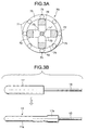
- the sheath heater 2 having the above-mentioned structure can be manufactured, for example, as follows. As shown in Fig. 3B, the heating coil and the control coil are, together with magnesia powder, enclosed in a sheath tube 11' having a diameter larger than the final diameter by an estimated value of reduction caused in the machining process. In the state, the sheath tube 11' is subjected to a rotational forging process (a swaging process) so that the main body 11a and the enlarged-diameter portion 11b are formed.
- a rotational forging process a swaging process
- the swaging process can be performed by using a swaging machine 70 structured, for example, as shown in Fig. 3A.
- the swaging machine 70 incorporates a plurality of dies 73 disposed around the sheath tube 11' and supported by corresponding hammers 72.
- the dies 73 are disposed in a main rotational shaft 74 so as to integrally be rotated.
- the main rotational shaft 74 is rotated in a cage 75 having a plurality of rollers 71 made of hardened steel.
- the dies 73 are opened by dint of the centrifugal force. Therefore, when the number of revolutions of the main rotational shaft 74 is made to be larger than a predetermined value, the compressing process using the dies 73 can be repeated.
- the main metal shell 3 is formed into a cylindrical shape having a through hole 4 formed in the axial direction, as shown in Fig. 1.
- the sheath heater 2 is inserted from either end of the opening so as to be secured in a state in which the leading end of the sheath tube 11 projects for a predetermined length.
- a tool engagement portion 9 having a hexagonal cross sectional shape to which a tool, such as a torque wrench or the like, for joining the glow plug 1 to the diesel engine is engaged is formed in the outer surface of the main metal shell 3.
- a joining thread portion 7 is formed to be continued from the tool engagement portion 9.
- the through hole 4 of the main metal shell 3 has an enlarged-diameter portion 4b positioned adjacent to an opening over which the sheath tube 11 projects and a small-diameter portion 4a formed to be continued from the enlarged-diameter portion 4b.
- the enlarged-diameter portion 11b formed adjacent to the base end of the sheath tube 11b is press-fit into the small-diameter portion 4a so as to be secured.
- a countersunk portion 3a is formed in the opposite opening of the through hole 4.
- a rubber "O" ring 15 (made of, for example, nylon) and an insulating bush 16 fitted to the outer surface of the energizing terminal shaft 13 are received in the countersunk portion 3a.
- a retaining ring 17 for preventing separation of the insulating bush 16 is fitted to the energizing terminal shaft 13 in the rear of the countersunk portion 3a.
- the retaining ring 17 has a crimping portion 17a formed on the outer surface thereof so as to be secured to the energizing terminal shaft 13.
- a knurled portion 13b for enlarging the crimping force is formed in the corresponding surface of the energizing terminal shaft 13.
- Reference numeral 19 represents a nut for securing a power supply cable to the energizing terminal shaft 13.
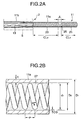
- a projection length L2 of the sheath tube 11 over the main metal shell 3 is 24 mm to 50 mm (preferably 28 mm to 40 mm). As shown in Fig. 2, the position of the leading end of the energizing terminal shaft 13 substantially coincides with the position of the end surface of the opening of the main metal shell 3.
- the glow plug 1 is joined to a cylinder block of the diesel engine at the thread portion 7 of the main metal shell 3 thereof.
- the leading end of the sheath tube 11 accommodating the heating coil 21 and the control coil 23 is located in a combustion chamber (or a sub-combustion chamber) of the engine.
- the control coil 23 In the initial stage of energization, the temperature of the control coil 23 of the sheath heater 2 of the glow plug 1 is low. Therefore, the control coil 23 has low electric resistance. Thus, a relatively large electric current passes through the heating coil 21 so that the temperature of the heating coil 21 is rapidly raised. When the temperature of the heating coil 21 is raised, the control coil 23 is heated with the heat of the heating coil 21. Thus, the electric resistance of the control coil 23 is raised, causing the value of the electric current which is supplied to the heating coil 21 to be reduced. As a result, a temperature rising characteristic of the heater is shown such that the temperature is rapidly raised in the initial stage of energization. Then, the supply of the electric current is prevented by the operation of the control coil so that the temperature is saturated.
- the main body 11a of the sheath tube 11 is formed into the cylindrical shape having a substantially constant outer diameter D1. Moreover, D1 is made to be 4.4 mm or smaller. Therefore, the excess-rise-preventive temperature rising characteristic, that is, a characteristic exhibiting an excellent quick heating characteristic can stably be realized with which the difference TP - TS between the peak temperature TP and the temperature TS realized after a lapse of 60 seconds is 50°C to 200°C, the peak temperature TP is 900°C to 1150°C and energizing time t800 required for the temperature to be raised to 800°C is 8 seconds or shorter.
- the thickness t of the sheath tube 11 is 0.3 mm to 0.75 mm. Moreover, the value of t/D1 on an assumption that the outer diameter is D1 is 0.08 to 0.2. Therefore, required heating performance can be realized even if the heater has a small diameter. Moreover, the sheath tube 11 has sufficiently large strength. Even if the heater is dropped during, for example, a joining operation, the heater is not easily broken.
- the radius difference CG between the inner diameter of the main body 11a of the sheath tube 11 and the outer diameter of each of the heating coil 21 and the control coil 23 satisfies the range from 0.1 mm to 0.8 mm. Therefore, short circuit does not easily occur between the inner surface of the sheath tube 11 and the coils 21 and 22. Therefore, the manufacturing yield can be improved.
- the ratio CL1/D1 of the coil length CL1 of the heating coil 21 and the outer diameter D1 of the main body of the sheath tube 11 shown in Fig. 2 is 1.6 to 3.5 (in this embodiment, it is about 2.5). Since the sheath tube 11 has a small diameter, heat radiation from the surface of the tube is enhanced as compared with the conventional sheath heater having a large diameter. Therefore, if CL1/D1 is smaller than 1.6, the length of the heating zone of the heating coil 21 is too small to obtain satisfactory heating performance. What is worse, the control coil cannot stably be heated. Therefore, a satisfactory excess-rise-preventive temperature rising characteristic cannot sometimes be obtained. If the CL1/D1 is larger than 4, there sometimes arises a problem in that the leading end of the sheath tube is not a portion generating a highest temperature.
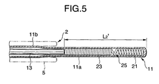
- Fig. 4 shows a modification of the glow plug 1 shown in Fig. 1 (note that common elements are given the same reference numerals and the common elements are omitted from description).
- the enlarged-diameter portion 11b of the sheath tube 11 formed adjacent to the base end of the same is made to be longer than that of the glow plug 1 shown in Fig. 1.
- the through hole 4 of the main metal shell 3 in the projection of the sheath tube 11 has not the enlarged-diameter portion 4b shown in Fig. 1. Therefore, a straight shape is formed.
- the enlarged-diameter portion 11b of the sheath tube 11 is joined to the through hole 4 by brazing.
- a countersunk portion 3a similar to that shown in Fig. 1 is provided for the opposite opening formed in the through hole 4.
- a seal ring (made of, for example, silicon rubber) 10 and a washer-type first insulating ring (made of heat resisting resin, such as bakelite) 12 are fit to the countersunk portion 3a in place of the insulating bush 16 shown in Fig. 1.
- a cylindrical projection formed at the edge of the opening of the countersunk portion 3a is crimped to the second insulating ring 14 so that a knurled portion 13b is formed.
- a second insulating ring 14 (same material and same shape as those of the first insulating ring 12) and a retaining ring 17 are, in this sequential order, joined and secured to the energizing terminal shaft 13 at a position in the rear of the knurled portion 13b.
- the leading end of the energizing terminal shaft 13 projects over the corresponding end of the opening of the main portion 5.
- the length L2' from the leading end of the energizing terminal shaft 13 to the leading end of the sheath tube 11 is 24 mm to 50 mm (preferably 24 mm to 42 mm).
- the glow plug 100 attains the following effect. That is, the leading end of the energizing terminal shaft 13 is introduced into the projection of the sheath tube 11 over the main metal shell 3. As a result, the portion of the sheath tube 11 which is in contact with the inner edge of the opening of the main metal shell 3 can be reinforced by the energizing terminal shaft 13, the contact portion being a portion to which strong bending force is exerted when lateral force is acted. As a result, breakage can satisfactorily be prevented even if a shock or the like is exerted.
- the glow plug 1 shown in Fig. 1 is superior to the glow plug 100 shown in Fig. 4 from the following viewpoint.
- the structure is formed such that the rear end portion of the energizing terminal shaft 13 is fixed by the retaining ring 17 through the insulating bush 16. Therefore, the number of required elements can be reduced and manufacturing can be facilitated as compared with the glow plug 100 shown in Fig. 4 and structured such that the first insulating ring 12 and the seal rig 10 are crimped by the crimping portion 3b; and the second insulating ring 14 and the retaining ring 17 are used for reinforcement.
- the glow plug 1 shown in Fig. 1 incorporates the flange portion 16a of the insulating bush 16 which elongates the distance from the inner edge of the opening of the main metal shell 3 to the outer surface of the energizing terminal shaft 13. Moreover, introduction of water into the portion including the energizing terminal shaft 13 through the gap between the insulating bush 16 and the main metal shell 3 can be prevented by the "O" ring 15.
- the glow plug 100 shown in Fig. 4 has the structure that the sheath tube 11 is joined to the main metal shell 3 by brazing. Therefore, design of the strength must be performed such that softening of the sheath tube 11 caused by an influence of the heat generated during the brazing operation is estimated.
- the glow plug 1 shown in Fig. 1 has the structure that the sheath tube 11 is press-fit into the main metal shell 3. Therefore, there is no apprehension of softening caused from the influence of heat. Thus, an advantage can be realized in that the effect of improving the strength by performing the machining process can effectively be used.
- a variety of glow plugs shown in Fig. 1 having the above-mentioned dimensions and made of the materials were manufactured except for the following specific conditions. Only the outer diameter D1 of the main body 11a of the sheath tube 11 were made to be to be 2.5 mm to 5.0 mm. To correspond to this, only the outer diameter d1 of each of the heating coil 21 and the control coil 23 were varied in a range from 1.5 mm to 2.5 mm. As an alternative to the cobalt-iron alloy, the materials of the control coil 23 were a nickel-plated iron wire (having the same diameter and the thickness of plating was about 1 ⁇ m) and a nickel wire (having the same diameter).
- the glow plug was allowed to stand at room temperature, and then a voltage of 11 V was applied to obtain temperature rising curves (temperature-time curves) as follows: the temperature was measured in a state in which the glow plug 1 was joined to a jig 200 structured as shown in Fig. 10.
- the jig 200 was made of carbon steel formed into an elongated cylindrical shape (having an outer diameter of 23 mm) .
- a plug receiving hole 201 was formed in the axial direction in the central portion of the jig 200.
- the glow plug 1 shown in Fig. 1 was joined to the jig 200 by inserting the leading end of the glow plug 1 into the plug receiving hole 201.
- the thread portion 7 was joined to a female thread portion 201a formed at an end portion of the plug receiving hole 201.
- the dimensions of the jig 200 were as illustrated (unit: mm).
- the leading end of the sheath tube 11 of the glow plug 1 projected over the end surface of the jig 200 by 8 mm in the joined state.
- thermocouple Pt/Pt - Rh
- Fig. 6 shows a temperature rising curve of the glow plug having a number 5.
- Fig. 7 shows a temperature rising curve of the glow plug having a number 1 and according to the comparative example.
- JL was varied in a range from 0.8 mm to 3 mm so that glow plugs each having an excellent quick heating characteristic and an excess-rise-preventive temperature rising characteristic were realized.
- a variety of the glow plugs shown in Fig. 1 having the above-mentioned dimensions and made of the above-mentioned materials were manufactured except for the following specific conditions. That is, the outer diameter D1 of the main body 11a of the sheath tube 11 of each glow plug was varied in a range from 3.0 mm to 4.4 mm. The thickness t of the main body 11a was varied in a range from 0.25 mm to 0.70 mm. Only the outer diameter d1 of each of the heating coil 21 and the control coil 23 was varied in a range from 1.5 mm to 3.0 mm.
- a pulse voltage (having a pulse length of 0.1 second) of 50 V was applied to each glow plug at room temperature to measure the level of the resistance of the glow plug.
- a result of the measurement was assumed to be R0.
- a voltage of 11 V was continuously applied for 30 seconds, and then a similar pulse voltage was applied.
- the level of the resistance of each glow plug was measured.
- a result of the measurement was assumed to be R1. If short circuit occurs between the sheath tube and the heating coil/control coil owing to heat, a substantial length of energized coil is shortened. Therefore, the measured resistance R1 is lowered. If a reduction ratio (R0 - R1)/R0) ⁇ 100 of R1 and R0 is not lower than 10 %, a determination was made that short circuit occurred.
- the glow plugs were accepted glow plugs (marked “A”: excellent). If one or more glow plugs encountered short circuit, the shorted glow plug(s) was(were) picked up (marked “B”: acceptable).
- Each glow plug was vertically held such that the sheath tube faced downwards and the initial distance from a concrete surface to the leading end of the sheath tube was 1 cm. Then, each glow plug was dropped, and then the distance was sequentially enlarged by 1 cm to repeat the dropping operation. After the dropping operation was completed, whether or not each sheath tube encountered bending and breakage was visually determined. Glow plugs free from breakage when the height from which the dropping operation was performed was 5 cm or greater were evaluated as excellent (A), 3 cm to 4 cm were evaluated as good (B) and 2 cm or smaller was evaluated as acceptable (C).
- each glow plug was held by a chuck such that the sheath tube is positioned horizontally, and then the glow plug was mounted on a bending testing machine. Moreover, the leading end of a bending punch was brought into contact with a position apart from the leading end of the sheath tube which projected side for a distance of 1 mm in the axial direction. Then, a cantilever bending test was performed at speed of the cross head of 1 mm/minute to measure a maximum bending load. The obtained value was employed as a bending strength.
- the outer diameter D1 of the main body 11a of the sheath tube 11 was fixed to 3.5 mm to vary the thickness t so as to measure the strength.
- FIG. 8 A graph formed by plotting the strength values and the probability of occurrence of short circuit is shown in Fig. 8. No. D1 (mm) t (mm) t/D1 D2 (mm) d1 (mm) CG (mm) d1/D2 Short Circuit Strength 31 3.50 0.25 0.07 3.00 1.90 0.55 0.63 A C 32 3.50 0.35 0.10 2.80 1.90 0.45 0.68 A B 33 3.50 0.50 0.14 2.50 1.90 0.30 0.76 A A 34 3.50 0.65 0.19 2.20 1.90 0.15 0.86 A A 35 3.50 0.75 0.21 2.00 1.90 0.05 0.95 B A 36 4.40 0.75 0.17 2.90 1.90 0.50 0.65 A A 37 4.40 0.35 0.19 3.70 1.90 0.90 0.51 B B 38 4.40 0.50 0.11 3.40 3.00 0.20 0.83 A A 39 3.00 0.40 0.13 2.20 1.90 0.15 0.86 A A 40 3.00 0.40 0.13 2.20 1.50 0.35 0.68 A A A
- the value of t/D1 must be 0.08 or greater. As can be understood from the results shown in Fig. 8, the corresponding strength must be 5 kg or greater. If the value of t/D1 is larger than 0.2, the probability of occurrence of short circuit was rapidly raised.
Landscapes
- Engineering & Computer Science (AREA)
- Chemical & Material Sciences (AREA)
- Combustion & Propulsion (AREA)
- Mechanical Engineering (AREA)
- General Engineering & Computer Science (AREA)
- Resistance Heating (AREA)
Applications Claiming Priority (4)
| Application Number | Priority Date | Filing Date | Title |
|---|---|---|---|
| JP12300198A JP3737879B2 (ja) | 1998-04-15 | 1998-04-15 | グロープラグ |
| JP12300298A JP3737880B2 (ja) | 1998-04-15 | 1998-04-15 | グロープラグ |
| JP12300298 | 1998-04-15 | ||
| JP12300198 | 1998-04-15 |
Publications (3)
| Publication Number | Publication Date |
|---|---|
| EP0950858A2 true EP0950858A2 (fr) | 1999-10-20 |
| EP0950858A3 EP0950858A3 (fr) | 2004-04-07 |
| EP0950858B1 EP0950858B1 (fr) | 2007-01-03 |
Family
ID=26460023
Family Applications (1)
| Application Number | Title | Priority Date | Filing Date |
|---|---|---|---|
| EP99302933A Revoked EP0950858B1 (fr) | 1998-04-15 | 1999-04-15 | Bougie à incandescence |
Country Status (3)
| Country | Link |
|---|---|
| US (1) | US6064039A (fr) |
| EP (1) | EP0950858B1 (fr) |
| DE (1) | DE69934628T2 (fr) |
Cited By (8)
| Publication number | Priority date | Publication date | Assignee | Title |
|---|---|---|---|---|
| WO2003095828A1 (fr) * | 2002-05-14 | 2003-11-20 | Ngk Spark Plug Co., Ltd. | Module de commande pour bougie de prechauffage et bougie de prechauffage |
| EP1217301A3 (fr) * | 2000-12-22 | 2006-07-26 | Ngk Spark Plug Co., Ltd. | Bougie à incandescence |
| EP2088373A1 (fr) | 2008-02-07 | 2009-08-12 | Robert Bosch GmbH | Bougie crayon de préchauffage métallique dotée d'une mesure de températures |
| ITPR20090056A1 (it) * | 2009-07-16 | 2011-01-17 | Etecno 1 Srl | Filamento resistivo per elementi riscaldatori e candelette per motori a combustione interna |
| DE10130488B4 (de) * | 2000-06-26 | 2011-07-21 | DENSO CORPORATION, Aichi-pref. | Glühkerze |
| ITPR20110093A1 (it) * | 2011-11-05 | 2013-05-06 | Etecno 1 S R L | Apparato riscaldatore con dispositivo di sicurezza |
| WO2015173017A1 (fr) * | 2014-05-13 | 2015-11-19 | Robert Bosch Gmbh | Electrode de prechauffage a joint d'isolation |
| EP2728257A3 (fr) * | 2012-11-01 | 2018-01-03 | Ngk Spark Plug Co., Ltd. | Procédé d'inspection et de fabrication de bougie de préchauffage, procédé d'inspection et de fabrication d'un dispositif chauffant gainé |
Families Citing this family (18)
| Publication number | Priority date | Publication date | Assignee | Title |
|---|---|---|---|---|
| DE19849120C2 (de) * | 1998-10-23 | 2000-09-28 | Beru Ag | Glühkerze |
| DE10053327C2 (de) * | 2000-10-27 | 2003-04-10 | Bosch Gmbh Robert | Stiftheizer |
| DE60228021D1 (de) * | 2001-05-28 | 2008-09-18 | Ngk Spark Plug Co | Heizung und Glühkerze |
| JP2002367760A (ja) * | 2001-06-11 | 2002-12-20 | Ngk Spark Plug Co Ltd | ヒータ及びグロープラグ |
| DE10128656A1 (de) * | 2001-06-15 | 2003-01-02 | Beru Ag | Stabglühkerze und Verfahren zu ihrer Herstellung |
| EP1406046B1 (fr) * | 2001-06-19 | 2014-12-31 | NGK Spark Plug Co., Ltd. | Bougie de prechauffage et procede de fabrication d'une bougie de prechauffage |
| JP4087303B2 (ja) * | 2002-07-19 | 2008-05-21 | 日本特殊陶業株式会社 | グロープラグの製造方法およびグロープラグの製造装置 |
| DE10248804A1 (de) * | 2002-10-19 | 2004-04-29 | Robert Bosch Gmbh | Mehrfachwendel für Glühstiftkerzen |
| US7332690B2 (en) * | 2003-09-05 | 2008-02-19 | Channel Products, Inc. | Hot wire igniter |
| JP2008157485A (ja) * | 2006-12-21 | 2008-07-10 | Denso Corp | グロープラグ |
| DE102008009429A1 (de) * | 2007-03-15 | 2008-09-18 | Robert Bosch Gmbh | Abdichtung für eine Glühkerze |
| JP5964547B2 (ja) * | 2011-01-25 | 2016-08-03 | 日本特殊陶業株式会社 | グロープラグおよびその製造方法 |
| WO2012160816A1 (fr) * | 2011-05-25 | 2012-11-29 | 日本特殊陶業株式会社 | Bougie à incandescence et procédé pour fabriquer une bougie à incandescence |
| KR101875621B1 (ko) * | 2012-04-09 | 2018-07-06 | 현대자동차 주식회사 | 글로우 플러그 및 이를 포함하는 전자식 써모스탯 |
| KR101638722B1 (ko) | 2012-04-16 | 2016-07-11 | 니혼도꾸슈도교 가부시키가이샤 | 글로 플러그 |
| US10352565B2 (en) * | 2012-08-08 | 2019-07-16 | Ngk Spark Plug Co., Ltd. | Glow plug |
| JP6370663B2 (ja) * | 2014-10-09 | 2018-08-08 | 日本特殊陶業株式会社 | グロープラグ |
| FR3033389B1 (fr) * | 2015-03-02 | 2018-11-16 | Robert Bosch Gmbh | Bougie de prechauffage ou de post-chauffage |
Citations (2)
| Publication number | Priority date | Publication date | Assignee | Title |
|---|---|---|---|---|
| JPS5960125A (ja) | 1982-09-28 | 1984-04-06 | Jidosha Kiki Co Ltd | デイ−ゼルエンジン用グロ−プラグ |
| JPH0399122A (ja) | 1989-09-11 | 1991-04-24 | Jidosha Kiki Co Ltd | 自己温度制御型グロープラグ |
Family Cites Families (12)
| Publication number | Priority date | Publication date | Assignee | Title |
|---|---|---|---|---|
| DE2802625C3 (de) * | 1978-01-21 | 1985-07-18 | BERU Ruprecht GmbH & Co KG, 7140 Ludwigsburg | Glühkerze |
| DE3038124A1 (de) * | 1980-10-09 | 1982-04-29 | Robert Bosch Gmbh, 7000 Stuttgart | Gluehstiftkerze fuer brennkaraftmaschinen |
| US4549071A (en) * | 1981-04-30 | 1985-10-22 | Jidosha Kiki Co., Ltd. | Glow plug for use in diesel engine |
| JPS5875627A (ja) * | 1981-10-28 | 1983-05-07 | Nippon Denso Co Ltd | デイ−ゼルエンジン用グロ−プラグ |
| JPS58145824A (ja) * | 1982-02-22 | 1983-08-31 | Nippon Denso Co Ltd | デイ−ゼルエンジン用グロ−プラグ |
| US4423309A (en) * | 1982-06-28 | 1983-12-27 | General Motors Corporation | Quick heat self regulating electric glow heater |
| JPS6066018A (ja) * | 1983-09-21 | 1985-04-16 | Ngk Spark Plug Co Ltd | セラミツクグロ−プラグ |
| DE3825012A1 (de) * | 1988-07-22 | 1990-01-25 | Beru Werk Ruprecht Gmbh Co A | Werkstoff fuer ein elektrisches widerstandselement mit positivem temperaturkoeffizienten |
| JP2745225B2 (ja) * | 1989-02-15 | 1998-04-28 | 自動車機器株式会社 | デイーゼルエンジン用グロープラグ |
| DE4014356A1 (de) * | 1990-05-04 | 1991-11-07 | Beru Werk Ruprecht Gmbh Co A | Gluehkerze |
| JP2570481Y2 (ja) * | 1991-05-30 | 1998-05-06 | 自動車機器株式会社 | 自己温度制御型グロープラグ |
| JP2735729B2 (ja) * | 1992-02-28 | 1998-04-02 | 京セラ株式会社 | セラミック発熱体 |
-
1999
- 1999-04-14 US US09/290,894 patent/US6064039A/en not_active Expired - Lifetime
- 1999-04-15 DE DE69934628T patent/DE69934628T2/de not_active Expired - Fee Related
- 1999-04-15 EP EP99302933A patent/EP0950858B1/fr not_active Revoked
Patent Citations (2)
| Publication number | Priority date | Publication date | Assignee | Title |
|---|---|---|---|---|
| JPS5960125A (ja) | 1982-09-28 | 1984-04-06 | Jidosha Kiki Co Ltd | デイ−ゼルエンジン用グロ−プラグ |
| JPH0399122A (ja) | 1989-09-11 | 1991-04-24 | Jidosha Kiki Co Ltd | 自己温度制御型グロープラグ |
Cited By (12)
| Publication number | Priority date | Publication date | Assignee | Title |
|---|---|---|---|---|
| DE10130488B4 (de) * | 2000-06-26 | 2011-07-21 | DENSO CORPORATION, Aichi-pref. | Glühkerze |
| EP1217301A3 (fr) * | 2000-12-22 | 2006-07-26 | Ngk Spark Plug Co., Ltd. | Bougie à incandescence |
| WO2003095828A1 (fr) * | 2002-05-14 | 2003-11-20 | Ngk Spark Plug Co., Ltd. | Module de commande pour bougie de prechauffage et bougie de prechauffage |
| US7319208B2 (en) | 2002-05-14 | 2008-01-15 | Ngk Spark Plug Co., Ltd. | Controller and glow plug for controlling energization modes |
| EP1505298A4 (fr) * | 2002-05-14 | 2011-09-07 | Ngk Spark Plug Co | Module de commande pour bougie de prechauffage et bougie de prechauffage |
| EP2378111A1 (fr) * | 2002-05-14 | 2011-10-19 | NGK Spark Plug Co., Ltd. | Bougie de préchauffage |
| EP2088373A1 (fr) | 2008-02-07 | 2009-08-12 | Robert Bosch GmbH | Bougie crayon de préchauffage métallique dotée d'une mesure de températures |
| ITPR20090056A1 (it) * | 2009-07-16 | 2011-01-17 | Etecno 1 Srl | Filamento resistivo per elementi riscaldatori e candelette per motori a combustione interna |
| EP2276320A1 (fr) * | 2009-07-16 | 2011-01-19 | Etecno 1 S.R.L. | Bougie pour moteurs à combustion, systèmes d'échappement et éléments chauffants |
| ITPR20110093A1 (it) * | 2011-11-05 | 2013-05-06 | Etecno 1 S R L | Apparato riscaldatore con dispositivo di sicurezza |
| EP2728257A3 (fr) * | 2012-11-01 | 2018-01-03 | Ngk Spark Plug Co., Ltd. | Procédé d'inspection et de fabrication de bougie de préchauffage, procédé d'inspection et de fabrication d'un dispositif chauffant gainé |
| WO2015173017A1 (fr) * | 2014-05-13 | 2015-11-19 | Robert Bosch Gmbh | Electrode de prechauffage a joint d'isolation |
Also Published As
| Publication number | Publication date |
|---|---|
| EP0950858A3 (fr) | 2004-04-07 |
| US6064039A (en) | 2000-05-16 |
| DE69934628D1 (de) | 2007-02-15 |
| EP0950858B1 (fr) | 2007-01-03 |
| DE69934628T2 (de) | 2007-10-11 |
Similar Documents
| Publication | Publication Date | Title |
|---|---|---|
| EP0950858B1 (fr) | Bougie à incandescence | |
| EP2410243A2 (fr) | Bougie de préchauffage | |
| JP2002359060A (ja) | ヒータ、及びヒータの製造方法 | |
| US6700317B2 (en) | Spark plug for an internal combustion engine and manufacturing method of the same | |
| JP3737880B2 (ja) | グロープラグ | |
| JPH11294769A (ja) | グロープラグ | |
| EP1448023B1 (fr) | Procédé de fabrication d'un élément chauffant blindé et procédé de fabrication d'une bougie à incandescence | |
| US7041938B2 (en) | Glow plug, glow plug mounting structure, and glow plug manufacturing method | |
| EP0887592B1 (fr) | Sonde/tube monolithique pour bougie | |
| JP3736137B2 (ja) | グロープラグの製造方法 | |
| EP0438097B1 (fr) | Bougie à incandescence pour moteurs diesel, en particulier pour véhicules automobiles comportant une gaine avec une réduction de diamètre de l'extrémité fermée | |
| JP6392000B2 (ja) | グロープラグ | |
| JP2000130752A (ja) | グロープラグ | |
| JP2002013734A (ja) | グロープラグ | |
| JP2005061828A (ja) | グロープラグ | |
| JP4123668B2 (ja) | グロープラグの製造方法 | |
| JP2000220828A (ja) | グロープラグ | |
| JP6537893B2 (ja) | グロープラグ | |
| EP1158245A1 (fr) | Bougie d'allumage à incandescence pour moteurs diesel et son procédé de fabrication | |
| EP3299719B1 (fr) | Bougie de préchauffage | |
| KR100915939B1 (ko) | 글로우 플러그의 하우징 제조방법 | |
| JP2003074848A (ja) | グロープラグ、グロープラグの取付構造及びグロープラグの製造方法 | |
| JP2006125776A (ja) | グロープラグ | |
| EP0429407A1 (fr) | Bougie d'allumage pour véhicules à moteur à combustion | |
| JP3830283B2 (ja) | グロープラグ |
Legal Events
| Date | Code | Title | Description |
|---|---|---|---|
| PUAI | Public reference made under article 153(3) epc to a published international application that has entered the european phase |
Free format text: ORIGINAL CODE: 0009012 |
|
| AK | Designated contracting states |
Kind code of ref document: A2 Designated state(s): AT BE CH CY DE DK ES FI FR GB GR IE IT LI LU MC NL PT SE |
|
| AX | Request for extension of the european patent |
Free format text: AL;LT;LV;MK;RO;SI |
|
| PUAL | Search report despatched |
Free format text: ORIGINAL CODE: 0009013 |
|
| AK | Designated contracting states |
Kind code of ref document: A3 Designated state(s): AT BE CH CY DE DK ES FI FR GB GR IE IT LI LU MC NL PT SE |
|
| AX | Request for extension of the european patent |
Extension state: AL LT LV MK RO SI |
|
| 17P | Request for examination filed |
Effective date: 20041004 |
|
| AKX | Designation fees paid |
Designated state(s): DE FR GB IT |
|
| GRAP | Despatch of communication of intention to grant a patent |
Free format text: ORIGINAL CODE: EPIDOSNIGR1 |
|
| GRAS | Grant fee paid |
Free format text: ORIGINAL CODE: EPIDOSNIGR3 |
|
| GRAA | (expected) grant |
Free format text: ORIGINAL CODE: 0009210 |
|
| AK | Designated contracting states |
Kind code of ref document: B1 Designated state(s): DE FR GB IT |
|
| REG | Reference to a national code |
Ref country code: GB Ref legal event code: FG4D |
|
| REF | Corresponds to: |
Ref document number: 69934628 Country of ref document: DE Date of ref document: 20070215 Kind code of ref document: P |
|
| ET | Fr: translation filed | ||
| PLBI | Opposition filed |
Free format text: ORIGINAL CODE: 0009260 |
|
| PLAX | Notice of opposition and request to file observation + time limit sent |
Free format text: ORIGINAL CODE: EPIDOSNOBS2 |
|
| 26 | Opposition filed |
Opponent name: ROBERT BOSCH GMBH ZGE2 SLICKERS Effective date: 20071001 Opponent name: BERU AG Effective date: 20070926 |
|
| PLAF | Information modified related to communication of a notice of opposition and request to file observations + time limit |
Free format text: ORIGINAL CODE: EPIDOSCOBS2 |
|
| PLBB | Reply of patent proprietor to notice(s) of opposition received |
Free format text: ORIGINAL CODE: EPIDOSNOBS3 |
|
| PLAB | Opposition data, opponent's data or that of the opponent's representative modified |
Free format text: ORIGINAL CODE: 0009299OPPO |
|
| R26 | Opposition filed (corrected) |
Opponent name: ROBERT BOSCH GMBH ZGE2 SLICKERS Effective date: 20071001 Opponent name: BERU AG Effective date: 20070926 |
|
| PGFP | Annual fee paid to national office [announced via postgrant information from national office to epo] |
Ref country code: IT Payment date: 20090427 Year of fee payment: 11 Ref country code: FR Payment date: 20090417 Year of fee payment: 11 Ref country code: DE Payment date: 20090409 Year of fee payment: 11 |
|
| PGFP | Annual fee paid to national office [announced via postgrant information from national office to epo] |
Ref country code: GB Payment date: 20090415 Year of fee payment: 11 |
|
| GBPC | Gb: european patent ceased through non-payment of renewal fee |
Effective date: 20100415 |
|
| REG | Reference to a national code |
Ref country code: FR Ref legal event code: ST Effective date: 20101230 |
|
| PG25 | Lapsed in a contracting state [announced via postgrant information from national office to epo] |
Ref country code: DE Free format text: LAPSE BECAUSE OF NON-PAYMENT OF DUE FEES Effective date: 20101103 |
|
| PG25 | Lapsed in a contracting state [announced via postgrant information from national office to epo] |
Ref country code: IT Free format text: LAPSE BECAUSE OF NON-PAYMENT OF DUE FEES Effective date: 20100415 Ref country code: GB Free format text: LAPSE BECAUSE OF NON-PAYMENT OF DUE FEES Effective date: 20100415 |
|
| RDAF | Communication despatched that patent is revoked |
Free format text: ORIGINAL CODE: EPIDOSNREV1 |
|
| RDAG | Patent revoked |
Free format text: ORIGINAL CODE: 0009271 |
|
| STAA | Information on the status of an ep patent application or granted ep patent |
Free format text: STATUS: PATENT REVOKED |
|
| PG25 | Lapsed in a contracting state [announced via postgrant information from national office to epo] |
Ref country code: FR Free format text: LAPSE BECAUSE OF NON-PAYMENT OF DUE FEES Effective date: 20100430 |
|
| 27W | Patent revoked |
Effective date: 20090910 |