EP0952105A1 - Systeme transporteur incline permettant de transporter des objets de grande taille - Google Patents
Systeme transporteur incline permettant de transporter des objets de grande taille Download PDFInfo
- Publication number
- EP0952105A1 EP0952105A1 EP98953045A EP98953045A EP0952105A1 EP 0952105 A1 EP0952105 A1 EP 0952105A1 EP 98953045 A EP98953045 A EP 98953045A EP 98953045 A EP98953045 A EP 98953045A EP 0952105 A1 EP0952105 A1 EP 0952105A1
- Authority
- EP
- European Patent Office
- Prior art keywords
- steps
- run
- enlarged
- tread
- tread face
- Prior art date
- Legal status (The legal status is an assumption and is not a legal conclusion. Google has not performed a legal analysis and makes no representation as to the accuracy of the status listed.)
- Withdrawn
Links
Images



Classifications
-
- B—PERFORMING OPERATIONS; TRANSPORTING
- B66—HOISTING; LIFTING; HAULING
- B66B—ELEVATORS; ESCALATORS OR MOVING WALKWAYS
- B66B23/00—Component parts of escalators or moving walkways
- B66B23/08—Carrying surfaces
- B66B23/12—Steps
-
- B—PERFORMING OPERATIONS; TRANSPORTING
- B66—HOISTING; LIFTING; HAULING
- B66B—ELEVATORS; ESCALATORS OR MOVING WALKWAYS
- B66B31/00—Accessories for escalators, or moving walkways, e.g. for sterilising or cleaning
- B66B31/006—Accessories for escalators, or moving walkways, e.g. for sterilising or cleaning for conveying hand carts, e.g. shopping carts
Definitions
- the present invention relates to a sloping transportation apparatus including an escalator, which has a step with an integral tread face permitting a large-sized object such as a wheelchair or large-sized baggage to be placed thereon and which is installed as a public passageway or in works to thereby contribute welfare and convenience.
- escalators capable of carrying a large-sized object such as a wheelchair have already been developed and put to practical use. All of these types of escalators look like an ordinary escalator in appearance but are provided with mechanisms for transforming a special group of steps into a level surface when it is necessary to transport the large sized object and an attendant's help is necessary for operating the mechanism and placing the object. Accordingly, ordinary users are excluded and it is necessary that the traveling operation be suspended for a considerably long time, giving rise to a problem that ordinary users have to endure inconvenience. In addition, the escalators of the aforementioned types are generally complicated in structure and costly. Further, a rise of the wheelchair carrying step is twice or three times as large as that of an ordinary rise, thus impeding passengers' steps.
- the present invention provides a sloping transportation apparatus including an escalator, which is capable of carrying a large-sized object without requiring a complicated transformation mechanism unlike conventional escalators for carrying a wheelchair and without the need of a large number of separate tracks, simple in structure and can curtail the labor and time associated with operation.
- Tracks employed in the invention, on which the steps travel, are similar to those to which steps of identical size are coupled, and at least one reduced step with a reduced run is connected before and behind an enlarged step having a single tread face permitting a large-sized object to be placed thereon.
- a step group have suitably varied shapes and dimensions, and no special manipulation is required substantially except for the operation of a wheel stopper mechanism.
- the group of steps including the enlarged step capable of carrying a large-sized object such as a wheelchair on its single enlarged tread face appears periodically.
- the run of the enlarged step is A and the run of ordinary steps is A0, then an excess of the run of the enlarged step is A - A0.
- At least one adjacent step preceding and succeeding the enlarged step has a reduced run so that the steps may be equally joined in a horizontal traveling section.
- the reduced run is set not to cause a passenger my inconvenience, and the reduced steps should preferably be small in number.
- the aforementioned excess of the run of the enlarged step may be equally divided between the adjacent reduced steps preceding and succeeding the enlarged step, and in this case a reduction X of the run required of each reduced step is (A - A0)/2.
- a reduction X of the run required of each reduced step is (A - A0)/2.
- approximate numerical values will be given as respective dimensions in the following description.
- the following describes cases where the invention is applied to a escalator of conventional type in which steps are reversed during circulation and the run A of the enlarged step is set to 1200 mm so that a large-sized motorized wheelchair can be placed thereon.
- the number of rollers for supporting the enlarged step with a large weight needs to be increased.
- the escalator must be constructed such that interference of the steps is never caused under the floor in a turning section.
- a curved section with a radius of curvature considerably greater than the radius of a driving gear is provided between the horizontal traveling section and the driving gear, thereby preventing interference of the steps under the floor.
- the structure of the steps needs to be determined such that the steps never interfere with each other and also have sufficient strength.
- a wheel receiving recess is formed on the enlarged step so that it may serve as a manipulation-free wheel stopper.
- Escalators can be classified into the conventional type in which the train of steps is reversed at the tuning section and then travels on the hidden side of the escalator to return to the original position, and a type in which two ways, forward and backward, are constituted by a series of steps (an escalator whose tread faces maintain their horizontal orientation throughout the entire traveling course is an apt example). In the following, such escalators will be described in detail along with the structure and function of the manipulation-free wheel stopper.
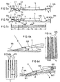
- an enlarged step 5 capable of carrying a large-sized object such as a wheelchair 100 is situated between a lower group of steps 1, 2, 3 and 4 and an upper group of steps 6, 7, 8 and 9, both in ascending order, the steps 1 and 9 have a run of 400 mm, the steps 2, 4, 6 and 8 have a run of 250 mm, and the steps 3 and 7 have a run of 300 mm.
- the run 300 mm is large enough for a passenger to stand on the tread face, and the run 250 mm is large enough for a passenger to put his/her foot on the tread face when ascending or descending the steps.
- the positions of some tread faces are shifted from the positions of corresponding supporting rollers, and thus special measures need to be taken for the step structure. Namely, different structures are required depending on articulation and driving types.
- steps connecting the respective tread faces to corresponding supporting rollers have a sectional form such that part thereof is elongated and extends beneath another step, as shown in the side view of FIG. 1.
- an auxiliary wheel 53 with high load bearing capacity is provided on the roof of a guide groove associated with at least one of the step roller 51 and the trailer roller 52.
- FIG. 1 illustrates the case where the auxiliary wheel 53 is made to roll on a guide surface 03 of the roof of a guide groove 01 associated with the step roller 51 (the guide groove for the step rollers 11, 21, 31, ... of the respective steps 1, 2, 3, ).
- curved portions with small curvature for example, arcuate guide portions 012 having a radius R2 considerably greater than the radius R5 of a pitch circle of a chain gear 05, are made to intervene between a horizontal straight traveling section 011 of the step roller guide groove 01 and an arcuate portion 013 corresponding to the chain gear 05.
- FIG. 2a curved portions with small curvature, for example, arcuate guide portions 012 having a radius R2 considerably greater than the radius R5 of a pitch circle of a chain gear 05, are made to intervene between a horizontal straight traveling section 011 of the step roller guide groove 01 and an arcuate portion 013 corresponding to the chain gear 05.
- a column 56 which extends downward from a moving handrail at a location below the step 5, is provided with lower and upper pin contacts 57a and 57b to be connected to parallel links, supporting rollers 57 and 58 are arranged symmetrically on front and rear sides of the lower pin, and an auxiliary wheel 59 is arranged (with its center located on the center line of the column 56) such that it rolls on a guide rail 09 provided on the roof of a guide groove 07 for the front supporting roller 57 (the guide groove for the front supporting rollers 17, 27, 37,... of the respective steps 1, 2, 3, ).
- a supporting roller and an auxiliary wheel are provided also on the outside of the step. It should be noted that since the direction is reversed in the opposite way after a turn by 180°, the positions of the front and rear rollers are reversed.
- the horizontal orientation of the steps is secured doubly by the two guide grooves for the supporting rollers and the parallel link mechanism, and it is especially advantageous that the horizontal orientation of the enlarged step can be maintained.
- a guide surface 078 of the horizontal straight traveling section and a guide surface 09 (radius of turn: R9) of a gear-driven arcuate turnaround section are connected by curves with small curvature (in the example shown in the figure, arcs 015 with a radius R3), thereby to reduce the value of k' shown in FIG. 4.
- the run A0 of ordinary tread faces is set to 400 mm, but mainly because of an oppressive feeling that a passenger has when standing between passengers, the fact is that the utilization factor of the steps is a slow as 50 to 75% even during the rush hours. If A0 is set to 500 mm, passengers hardly feel oppressed; accordingly, the utilization factor improves and strangeness in shape of the steps adjacent to the enlarged step lessens.
- the angle ⁇ of inclination of the escalator is set to 30°
- the rise H is 250 mm, which is somewhat too large; however, if ⁇ is set to 27°, then H is 227.0 mm, which falls within the practically allowable range.
- the steps have relatively moderate sectional forms.
- the auxiliary wheel and the turning section are basically identical in shape with those described in (1a) above.
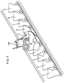
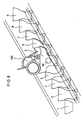
- a train of steps including the enlarged step 5 in the middle has a sectional form as shown in FIG. 9.
- the auxiliary wheel and the turning section are basically identical with those described in (1a) and (2a) above.
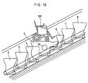
- a train of steps including the enlarged step in the middle has a sectional form as shown in FIG. 10.
- the auxiliary wheels and the guide surface of the turnaround section are basically identical with those described in (1b) and (2b) above.
- FIG. 3a An escalator for carrying a wheelchair is provided with a wheel stopper mechanism 55 (FIG. 3a), which is retracted when not in use and is pulled out when a wheelchair is placed on the escalator, to prevent the wheelchair from falling.
- a wheel stopper mechanism 55 (FIG. 3a)
- FIGS. 5a to 5c show different structures to cope with various types and dimensions of wheelchairs.
- FIG. 5a is a side view of a structure for use with the conventional chain-driven type
- FIG. 5b is a side view of a structure for use with the horizontal orientation maintenance and circulation type.
- arcuate portions are formed on front and rear end portions, respectively, so as to be symmetrical with respect to a horizontal center line on the tread face.
- the coefficient of static friction between the wheelchair tire and the tread face is 0.6 to 1.0 at most.
- the tire received in the recess is braked and never falls but yet can be moved beyond C2, and where the tire diameter exceeds 400 mm, the tire can be placed stably between C1 and C2 (slightly chamfered).
- the wheel stopper need not be formed over the entire lateral width but may be provided only in regions where the main tires pass, and this is convenient also for ordinary passengers.
- the tire region 300 to 750 mm
- a pitch U is set to be greater than a pitch V (see FIG. 5c) for the passenger regions P1 and P2.
- an angle ⁇ of inclination of a comb 005 is set at 15° corresponding to a design limit, and a depth or height G of the grooves is set to about 62 mm, taking account of the thickness and spacing of distal tooth portions of the comb.
- a movable comb 006 shown in FIG. 6d may be used, wherein the comb 006 is swingably supported on a horizontal shaft 002 parallel with a floor surface 00, and comb guide rollers 003 located at the distal tooth portion of the comb 006 are guided along comb tooth guide surfaces 401, 501, 601, etc. (partly omitted in the figure) of the steps 4, 5, 6, etc.; however, this method requires complicated structure and cannot be said practical.
- the present invention does not require a mechanism for transforming the escalator so as to carry a wheelchair, and therefore, except for the switch operation before a wheelchair is placed, the switch operation for the wheel stopper (this is unnecessary in the case of the recess type wheel stopper) after the escalator is stopped at a predetermined position, and the switch operation for starting, no other manipulations are required such as confirmation of a preliminary mechanism for the transformation, confirmation of the results of the transformation, and the restoration after use, whereby the cost and time can be saved, safety can be improved, and attendance of the operator may itself be unnecessary as the case may be.
- the rise at the wheelchair carrying section is twice or three times as large as the normal height, constituting a hindrance to passengers' ascent or descent.
- the rise may somewhat increase but does not constitute a hindrance.
- an enlarged step can be easily provided in a plurality of regions of an escalator, thus shortening the users' waiting time.
- Existing transformation type escalators are usually provided with a single enlarged step to prevent the structure from becoming complicated, and this results in an increase in the waiting time.
- control operation is performed such that upon depression of a button, a proximity switch sensor closest to an arriving wheelchair is set operative; followed by reduction in speed and then stop of the escalator.
- the enlarged step capable of carrying a large-sized object such as a wheelchair automatically and periodically appears without requiring special operation, and a large-sized object such as a wheelchair can be carried even in a perfectly manipulation-free fashion. Also, the reduced steps do not hinder ordinary passengers' standing or ascent or descent.
Landscapes
- Escalators And Moving Walkways (AREA)
Applications Claiming Priority (3)
| Application Number | Priority Date | Filing Date | Title |
|---|---|---|---|
| JP34843797 | 1997-11-13 | ||
| JP9348437A JPH11139738A (ja) | 1997-11-13 | 1997-11-13 | 大物搭載傾斜搬送装置 |
| PCT/JP1998/005127 WO1999025635A1 (fr) | 1997-11-13 | 1998-11-13 | Systeme transporteur incline permettant de transporter des objets de grande taille |
Publications (2)
| Publication Number | Publication Date |
|---|---|
| EP0952105A1 true EP0952105A1 (fr) | 1999-10-27 |
| EP0952105A4 EP0952105A4 (fr) | 2002-04-24 |
Family
ID=18397008
Family Applications (1)
| Application Number | Title | Priority Date | Filing Date |
|---|---|---|---|
| EP98953045A Withdrawn EP0952105A4 (fr) | 1997-11-13 | 1998-11-13 | Systeme transporteur incline permettant de transporter des objets de grande taille |
Country Status (4)
| Country | Link |
|---|---|
| US (1) | US6098779A (fr) |
| EP (1) | EP0952105A4 (fr) |
| JP (1) | JPH11139738A (fr) |
| WO (1) | WO1999025635A1 (fr) |
Cited By (1)
| Publication number | Priority date | Publication date | Assignee | Title |
|---|---|---|---|---|
| ES2333640A1 (es) * | 2009-06-26 | 2010-02-24 | Thyssenkrupp Elevator Innovation Center, S.A. | Sistema praa transporte para pasajeros/mercancias. |
Families Citing this family (3)
| Publication number | Priority date | Publication date | Assignee | Title |
|---|---|---|---|---|
| DE10065470B4 (de) * | 2000-12-28 | 2011-02-17 | Aleris Aluminum Vogt Gmbh | Verfahren zur Herstellung eines Kühlelements für elektrische, insbesondere elektronische, Bauelemente |
| JP4458770B2 (ja) * | 2002-11-25 | 2010-04-28 | 東芝エレベータ株式会社 | コンベア装置 |
| US10414632B1 (en) * | 2019-05-13 | 2019-09-17 | Constanza Terry | Escalator system for facilitating the transport of goods |
Family Cites Families (9)
| Publication number | Priority date | Publication date | Assignee | Title |
|---|---|---|---|---|
| JPS5641555B2 (fr) * | 1973-10-29 | 1981-09-29 | ||
| JPS51102884A (en) * | 1975-03-04 | 1976-09-10 | Mitsubishi Electric Corp | Esukareetano hansotai |
| JPS58196359A (ja) * | 1982-05-12 | 1983-11-15 | Nissan Motor Co Ltd | ロツクアツプ式トルクコンバ−タ |
| JPS58196359U (ja) * | 1982-06-21 | 1983-12-27 | 三菱電機株式会社 | 乗客コンベアの制御装置 |
| JP3080376B2 (ja) * | 1989-09-07 | 2000-08-28 | 雅男 窪田 | 連結式搬送機械 |
| JPH03166192A (ja) * | 1989-11-24 | 1991-07-18 | Masao Kubota | エスカレーター |
| JP3110817B2 (ja) * | 1991-09-09 | 2000-11-20 | 有限会社コンペックス | 事務所故紙の処理装置 |
| JPH0967077A (ja) * | 1995-06-20 | 1997-03-11 | Masao Kubota | 大形物用連結搬送装置 |
| WO1997006091A1 (fr) * | 1995-08-07 | 1997-02-20 | Masao Kubota | Dispositif de transport de type a connexion pour transporter un objet volumineux |
-
1997
- 1997-11-13 JP JP9348437A patent/JPH11139738A/ja active Pending
- 1997-11-13 US US09/341,525 patent/US6098779A/en not_active Expired - Fee Related
-
1998
- 1998-11-13 EP EP98953045A patent/EP0952105A4/fr not_active Withdrawn
- 1998-11-13 WO PCT/JP1998/005127 patent/WO1999025635A1/fr not_active Ceased
Cited By (2)
| Publication number | Priority date | Publication date | Assignee | Title |
|---|---|---|---|---|
| ES2333640A1 (es) * | 2009-06-26 | 2010-02-24 | Thyssenkrupp Elevator Innovation Center, S.A. | Sistema praa transporte para pasajeros/mercancias. |
| ES2333640B1 (es) * | 2009-06-26 | 2010-09-13 | Thyssenkrupp Elevator Innovation Center, S.A. | Sistema de transporte para pasajeros/mercancias. |
Also Published As
| Publication number | Publication date |
|---|---|
| JPH11139738A (ja) | 1999-05-25 |
| US6098779A (en) | 2000-08-08 |
| WO1999025635A1 (fr) | 1999-05-27 |
| EP0952105A4 (fr) | 2002-04-24 |
Similar Documents
| Publication | Publication Date | Title |
|---|---|---|
| US6098779A (en) | Sloping transportation apparatus for carrying large sized objects | |
| JPH03128885A (ja) | エスカレータ装置 | |
| US5472075A (en) | Escalator apparatus | |
| CN101918301A (zh) | 电扶梯 | |
| EP0424209B1 (fr) | Escalier roulant avec des hauteurs de marches verticales planaires et avec vitesse costante horizontale | |
| GB2173757A (en) | Improvements in passenger conveyors | |
| JPH0357024B2 (fr) | ||
| US6102186A (en) | Escalator balustrade/handrail construction | |
| EP1101724A2 (fr) | Balustrades pour escalier roulant | |
| JP2846568B2 (ja) | 乗客コンベア | |
| EP1331194A2 (fr) | Escalier roulant avec section incliné à haute vitesse | |
| JPH028190A (ja) | 傾斜自在型エスカレータ | |
| JPH09301662A (ja) | 乗客コンベアの踏板 | |
| JPH02225288A (ja) | 乗客コンベアの乗降口 | |
| JP2617288B2 (ja) | 車椅子等を運搬するエスカレーター | |
| JPS61221085A (ja) | 車椅子等を運搬するエスカレ−タ− | |
| JP2935049B2 (ja) | 電動道路 | |
| JP2505600B2 (ja) | 中間踊り場付きエスカレ―タ | |
| JP2516461Y2 (ja) | 動く歩道等の案内装置 | |
| JPH1059668A (ja) | 可変速型乗客コンベヤ | |
| JPS6138060B2 (fr) | ||
| JPH0649556B2 (ja) | エスカレ−タ | |
| JPH115680A (ja) | 可変速型乗客コンベヤ | |
| JPS62218388A (ja) | エスカレ−タ | |
| JPH0967077A (ja) | 大形物用連結搬送装置 |
Legal Events
| Date | Code | Title | Description |
|---|---|---|---|
| PUAI | Public reference made under article 153(3) epc to a published international application that has entered the european phase |
Free format text: ORIGINAL CODE: 0009012 |
|
| 17P | Request for examination filed |
Effective date: 19990804 |
|
| AK | Designated contracting states |
Kind code of ref document: A1 Designated state(s): DE GB |
|
| A4 | Supplementary search report drawn up and despatched |
Effective date: 20020312 |
|
| AK | Designated contracting states |
Kind code of ref document: A4 Designated state(s): DE GB |
|
| RIC1 | Information provided on ipc code assigned before grant |
Free format text: 7B 66B 23/12 A, 7B 66B 29/08 B, 7B 66B 31/00 B |
|
| STAA | Information on the status of an ep patent application or granted ep patent |
Free format text: STATUS: THE APPLICATION HAS BEEN WITHDRAWN |
|
| 18W | Application withdrawn |
Withdrawal date: 20020517 |