EP0964419A1 - Flache thermische Sicherung und Herstellungsverfahren - Google Patents
Flache thermische Sicherung und Herstellungsverfahren Download PDFInfo
- Publication number
- EP0964419A1 EP0964419A1 EP99301462A EP99301462A EP0964419A1 EP 0964419 A1 EP0964419 A1 EP 0964419A1 EP 99301462 A EP99301462 A EP 99301462A EP 99301462 A EP99301462 A EP 99301462A EP 0964419 A1 EP0964419 A1 EP 0964419A1
- Authority
- EP
- European Patent Office
- Prior art keywords
- belt
- shaped lead
- lead conductors
- base film
- resin base
- Prior art date
- Legal status (The legal status is an assumption and is not a legal conclusion. Google has not performed a legal analysis and makes no representation as to the accuracy of the status listed.)
- Granted
Links
- 238000004519 manufacturing process Methods 0.000 title claims description 15
- 239000011347 resin Substances 0.000 claims abstract description 117
- 229920005989 resin Polymers 0.000 claims abstract description 117
- 239000004020 conductor Substances 0.000 claims abstract description 92
- 239000010408 film Substances 0.000 claims abstract description 81
- 239000013039 cover film Substances 0.000 claims abstract description 55
- 229910000743 fusible alloy Inorganic materials 0.000 claims abstract description 54
- 230000004907 flux Effects 0.000 claims abstract description 19
- -1 polyethylene terephthalate Polymers 0.000 claims description 9
- PXHVJJICTQNCMI-UHFFFAOYSA-N Nickel Chemical compound [Ni] PXHVJJICTQNCMI-UHFFFAOYSA-N 0.000 claims description 4
- 230000008878 coupling Effects 0.000 claims description 4
- 238000010168 coupling process Methods 0.000 claims description 4
- 238000005859 coupling reaction Methods 0.000 claims description 4
- 238000000034 method Methods 0.000 claims description 4
- RYGMFSIKBFXOCR-UHFFFAOYSA-N Copper Chemical compound [Cu] RYGMFSIKBFXOCR-UHFFFAOYSA-N 0.000 claims description 3
- 239000004952 Polyamide Substances 0.000 claims description 3
- 239000004698 Polyethylene Substances 0.000 claims description 3
- 239000004642 Polyimide Substances 0.000 claims description 3
- 239000004721 Polyphenylene oxide Substances 0.000 claims description 3
- UCKMPCXJQFINFW-UHFFFAOYSA-N Sulphide Chemical compound [S-2] UCKMPCXJQFINFW-UHFFFAOYSA-N 0.000 claims description 3
- 229910052802 copper Inorganic materials 0.000 claims description 3
- 239000010949 copper Substances 0.000 claims description 3
- 229920002492 poly(sulfone) Polymers 0.000 claims description 3
- 229920002647 polyamide Polymers 0.000 claims description 3
- 229920001707 polybutylene terephthalate Polymers 0.000 claims description 3
- 229920000573 polyethylene Polymers 0.000 claims description 3
- 229920000139 polyethylene terephthalate Polymers 0.000 claims description 3
- 239000005020 polyethylene terephthalate Substances 0.000 claims description 3
- 229920001721 polyimide Polymers 0.000 claims description 3
- 229920006380 polyphenylene oxide Polymers 0.000 claims description 3
- 229910052782 aluminium Inorganic materials 0.000 claims description 2
- XAGFODPZIPBFFR-UHFFFAOYSA-N aluminium Chemical compound [Al] XAGFODPZIPBFFR-UHFFFAOYSA-N 0.000 claims description 2
- 229910052759 nickel Inorganic materials 0.000 claims description 2
- 239000000463 material Substances 0.000 claims 1
- 238000003466 welding Methods 0.000 description 12
- 230000002093 peripheral effect Effects 0.000 description 11
- RSWGJHLUYNHPMX-UHFFFAOYSA-N Abietic-Saeure Natural products C12CCC(C(C)C)=CC2=CCC2C1(C)CCCC2(C)C(O)=O RSWGJHLUYNHPMX-UHFFFAOYSA-N 0.000 description 10
- KHPCPRHQVVSZAH-HUOMCSJISA-N Rosin Natural products O(C/C=C/c1ccccc1)[C@H]1[C@H](O)[C@@H](O)[C@@H](O)[C@@H](CO)O1 KHPCPRHQVVSZAH-HUOMCSJISA-N 0.000 description 10
- KHPCPRHQVVSZAH-UHFFFAOYSA-N trans-cinnamyl beta-D-glucopyranoside Natural products OC1C(O)C(O)C(CO)OC1OCC=CC1=CC=CC=C1 KHPCPRHQVVSZAH-UHFFFAOYSA-N 0.000 description 10
- 238000010586 diagram Methods 0.000 description 9
- 229910045601 alloy Inorganic materials 0.000 description 7
- 239000000956 alloy Substances 0.000 description 7
- 125000006850 spacer group Chemical group 0.000 description 6
- HBBGRARXTFLTSG-UHFFFAOYSA-N Lithium ion Chemical compound [Li+] HBBGRARXTFLTSG-UHFFFAOYSA-N 0.000 description 5
- 229910001416 lithium ion Inorganic materials 0.000 description 5
- 230000005855 radiation Effects 0.000 description 5
- 239000000853 adhesive Substances 0.000 description 4
- 230000001070 adhesive effect Effects 0.000 description 4
- 238000009413 insulation Methods 0.000 description 4
- 238000003825 pressing Methods 0.000 description 4
- 238000007789 sealing Methods 0.000 description 4
- 230000002159 abnormal effect Effects 0.000 description 3
- 230000002950 deficient Effects 0.000 description 3
- 238000002844 melting Methods 0.000 description 3
- 230000008018 melting Effects 0.000 description 3
- 230000003213 activating effect Effects 0.000 description 2
- 239000003795 chemical substances by application Substances 0.000 description 2
- HPNMFZURTQLUMO-UHFFFAOYSA-N diethylamine Chemical compound CCNCC HPNMFZURTQLUMO-UHFFFAOYSA-N 0.000 description 2
- 238000010438 heat treatment Methods 0.000 description 2
- 229910052751 metal Inorganic materials 0.000 description 2
- 239000002184 metal Substances 0.000 description 2
- VEXZGXHMUGYJMC-UHFFFAOYSA-N Hydrochloric acid Chemical compound Cl VEXZGXHMUGYJMC-UHFFFAOYSA-N 0.000 description 1
- CPELXLSAUQHCOX-UHFFFAOYSA-N Hydrogen bromide Chemical compound Br CPELXLSAUQHCOX-UHFFFAOYSA-N 0.000 description 1
- 230000004913 activation Effects 0.000 description 1
- 230000007423 decrease Effects 0.000 description 1
- 238000007599 discharging Methods 0.000 description 1
- 229920006351 engineering plastic Polymers 0.000 description 1
- 230000004048 modification Effects 0.000 description 1
- 238000012986 modification Methods 0.000 description 1
- 238000012856 packing Methods 0.000 description 1
- 238000000926 separation method Methods 0.000 description 1
- 238000005728 strengthening Methods 0.000 description 1
Images




Classifications
-
- H—ELECTRICITY
- H01—ELECTRIC ELEMENTS
- H01H—ELECTRIC SWITCHES; RELAYS; SELECTORS; EMERGENCY PROTECTIVE DEVICES
- H01H85/00—Protective devices in which the current flows through a part of fusible material and this current is interrupted by displacement of the fusible material when this current becomes excessive
-
- H—ELECTRICITY
- H01—ELECTRIC ELEMENTS
- H01H—ELECTRIC SWITCHES; RELAYS; SELECTORS; EMERGENCY PROTECTIVE DEVICES
- H01H37/00—Thermally-actuated switches
- H01H37/74—Switches in which only the opening movement or only the closing movement of a contact is effected by heating or cooling
- H01H37/76—Contact member actuated by melting of fusible material, actuated due to burning of combustible material or due to explosion of explosive material
- H01H37/761—Contact member actuated by melting of fusible material, actuated due to burning of combustible material or due to explosion of explosive material with a fusible element forming part of the switched circuit
-
- H—ELECTRICITY
- H01—ELECTRIC ELEMENTS
- H01H—ELECTRIC SWITCHES; RELAYS; SELECTORS; EMERGENCY PROTECTIVE DEVICES
- H01H37/00—Thermally-actuated switches
-
- Y—GENERAL TAGGING OF NEW TECHNOLOGICAL DEVELOPMENTS; GENERAL TAGGING OF CROSS-SECTIONAL TECHNOLOGIES SPANNING OVER SEVERAL SECTIONS OF THE IPC; TECHNICAL SUBJECTS COVERED BY FORMER USPC CROSS-REFERENCE ART COLLECTIONS [XRACs] AND DIGESTS
- Y10—TECHNICAL SUBJECTS COVERED BY FORMER USPC
- Y10T—TECHNICAL SUBJECTS COVERED BY FORMER US CLASSIFICATION
- Y10T29/00—Metal working
- Y10T29/49—Method of mechanical manufacture
- Y10T29/49002—Electrical device making
- Y10T29/49107—Fuse making
Definitions
- the present invention relates to a thin type thermal fuse and a manufacturing method thereof, which is used for manufacturing a thermal fuse for protecting a lithium ion secondary battery from excessive discharge and excessive charge, for example.
- a large capacity battery such as a lithium ion secondary battery has been employed as a power source for a portable electric device.
- Such a thermal fuse for protecting the battery is required to be a thin type.
- a thin type thermal fuse there has been known one which is arranged in the following manner. Tip portions of a pair of belt-shaped lead conductors are fixed on one surface of a resin base film. A low melting-point fusible alloy piece is coupled between the tip portions of the belt-shaped lead conductors. A resin cover film is disposed on the one surface of the resin base film. The space between the films at the peripheries of both the resin films is sealed by an adhesive and also the space between the resin cover film and the belt-shaped lead conductors is sealed by an adhesive.
- the aforesaid thin type thermal fuse becomes likely inoperative by the following reasons, for example. That is, the ratio (surface area / sectional area) of the belt-shaped lead conductor is quite larger than that of a circular lead conductor. An amount of dissipation heat is too large at the time of connecting the low melting-point fusible alloy piece to the lead conductor by the welding. The defective welding connection is likely occurred. This welded connection is in a state that the alloy piece is connected to the lead conductor in a point-fashion at the one portion of melted metal being spread and remaining portions of the melted metal merely contact to the conductors, and so it is difficult to detect the defective welding even by measuring the resistance value.
- the low melting-point fusible alloy piece being fused becomes spherical due to the surface tension and then separated into several pieces.
- the aforesaid thin type thermal fuse since the melted alloy contacts in a circular plate fashion to the inner wall of the thin space, the surface area of the melted alloy on which the surface tension acts is small. Accordingly, the separation function of the alloy piece being fused is essentially degraded as compared with that of the aforesaid spherical shape of the alloy piece being fused of the alloy type thermal fuse.
- a thin type thermal fuse according to the present invention is coprised of: a resin base film; a pair of belt-shaped lead conductors, tip portions of the pair of belt-shaped lead conductors being fixed on the resin base film; a low melting-point fusible alloy piece coupled between the tip end portions of the belt-shaped lead conductors; flux applied on the low melting-point fusible alloy piece; a resin cover film which is disposed on a one surface of the resin base film so that a space between said films at peripheries of both the resin cover film and the resin base film is sealed and a space between the resin cover film and the belt-shaped lead conductors is sealed; wherein a relation of (V/L) 1/2 /d ⁇ 1.8 is satisfied, where a distance between the tip portions of the belt-shaped lead conductors is set to be L, a volume of the low melting-point fusible alloy piece is set to be V and a distance between the front surface of the resin base film and an inner surface of the resin cover film is set to be d
- a method of manufacturing a thin type thermal fuse comprises the steps of: fixing tip portions of a pair of belt-shaped lead conductors on a resin base film; coupling a low melting-point fusible alloy piece between the tip end portions of the belt-shaped lead conductors; applying flux on the low melting-point fusible alloy piece; disposing a resin cover film on a one surface of the resin base film so that a space between said films at peripheries of both the resin cover film and the resin base film is sealed and a space between the resin cover film and the belt-shaped lead conductors is sealed; wherein a relation of (V/L) 1/2 /d ⁇ 1.8 is satisfied, where a distance between the tip portions of the belt-shaped lead conductors is set to be L, a volume of the low melting-point fusible alloy piece is set to be V and a distance between the front surface of the resin base film and an inner surface of the resin cover film is set to be d.
- Fig. 1A shows a thin type thermal fuse according to a first embodiment of the present invention
- Fig. 1B is a sectional view taken along a line B-B in Fig. 1A.
- reference numeral 11 denotes a resin base film; and 2, belt-shaped lead conductors each having a tip portion fixed to the resin base film 11 by the thermal fusing or an adhesive.
- Reference numeral 3 denotes a low melting-point fusible alloy piece coupled between the tip portions of the belt-shaped lead conductors 2, 2 by the welding; 4, a flux coated on the low melting-point fusible alloy piece; and 12, a resin cover film disposed on the one surface of the resin base film 11 such that the space between the films at the peripheries of the resin cover film and the space between the resin cover film and the belt-shaped lead conductors are sealed.
- an activated rosin is generally used, and the activated rosin to which an activating agent for strengthening activation is used.
- the rosin there are a natural rosin, a modified rosin such as a water-added rosin, an inhomogeneous rosin and a polymerized rosin, and a purified rosin thereof.
- the activating agent hydrochloride of diethylamine, hydrobromide of diethylamine and the like can be used. Wax is sometime mixed with the flux to adjust the melting point of the flux.
- the low melting-point fusible alloy piece 3 is formed by a round wire or a strap or flat wire made of low melting-point fusible alloy whose melting point is adjusted in accordance with the operation temperature.
- the diameter of the round wire is usually set in a range of 500 ⁇ m to 1000 ⁇ m.
- the flat wire employed is set to have the same cross area as that of the round wire. Namely, the cross area of the wire is from about 0.78 to 3.2 mm 2 .
- the belt-shaped lead conductor 2 may be made of copper, aluminum, nickel or the like, for example.
- the belt-shaped lead conductor usually may have a thickness in a range of 50 ⁇ m to 200 ⁇ m, preferably about 100 ⁇ m, and have a width in a range of 2mm to 5mm, preferably about 3mm.
- the length of the belt-shaped lead conductor is generally in the range of 4 to 31mm, preferably 9 to 23mm.
- the resin base film 11 and the resin cover film 12 may be formed of engineering plastics such as polyethylene terephthalate, polyamide, polyimide, polybutylene terephthalate, polyphenylene oxide, polyethylene sulfide, polysulfone, or the like. Usually, the same kind of film is employed for the resin base film and the resin cover film, but different kinds of films may be employed for these films.
- the thickness of each of these films is set in a range of 50 ⁇ m to 500 ⁇ m.
- the length of the resin base film 11 is generally in the range of 7 to 18mm, preferably 7 to 12mm.
- the width is generally in the range of 2.5 to 10mm, preferably, 3 to 7mm.
- the tip portions of the pair of the belt-shaped lead conductors 2, 2 are fixed on the one surface of the resin base film 11 by the thermal pressing, ultrasonic fusing, adhesive or the like. Then, the low melting-point fusible alloy piece 3 is connected to the tip portions of the belt-shaped lead conductors 2, 2 by the resistor welding or the like so that the tip portions thereof are coupled by the low melting-point fusible alloy piece.
- This welding is performed in a manner that about 2 to 30 % of the entire surface area of the low melting-point fusible alloy piece serves as the contact surface.
- the exposed surface area of the belt-shaped lead conductors (the surface area of the tip portions of the belt-shaped lead conductors except for the sealed portions thereof) is not less than about 2 to 30 % of the entire surface area of the low melting-point fusible alloy piece.
- the flux 4 is coated and solidified over the low melting-point fusible alloy piece 3 with a predetermined thickness d.
- the thickness d of the flux is set to satisfy the aforesaid relation of (V/L) 1/2 /d ⁇ 1.8.
- the resin cover film 12 is disposed on the one surface of the resin base film 11. Thereafter, in the state that the resin cover film 12 is made contact to the flux, the resin base film 11 is coupled to the resin cover film 12 and also the resin cover film 12 is coupled to the non-sealed portions 20 of the belt-shaped lead conductors by means of the heat sealing, ultrasonic fusing, laser radiation, or the like. Thus, the fabrication of the thin type thermal fuse shown in Fig. 1 is completed.
- Table 1 exhibits the experimental result which was obtained by using the following samples.
- the number of samples for each case is 10.
- the samples were dipped into the heated oil of 95 °C for two minutes and the samples having not resulted in non-conductive state were determined to be inoperative.
- Each of the samples was formed in a manner that a round line with a diameter of 550 ⁇ m and a melting point of 93°C was employed as the low melting-point fusible alloy piece 3. Rosin was used as the flux 4.
- the values L and V were changed (the value V was changed by changing the length of the low melting-point fusible alloy piece).
- the belt-shaped lead conductors (formed by using belt-shaped copper with a thickness of 0.1 mm and a width of 4 mm) and the low melting-point fusible alloy piece were coupled by the welding particularly in a state where the surface of the belt-shaped lead conductors was slightly oxidized to forcedly place in an insufficient state.
- the thin type thermal fuse in the manufacturing method of the thin type thermal fuse according to the first embodiment of the present invention, by merely restricting the thickness d of the flux 4 covering the low melting-point fusible alloy piece 3 and then by normally coupling the resin base film 11 with the resin cover film 12 and coupling the resin cover film 12 with the belt-shaped lead conductors, the thin type thermal fuse satisfying the aforesaid condition of (V/L) 1/2 /d ⁇ 1.8 can be manufactured. Accordingly, the thin type thermal fuse capable of making the generation ratio of inoperability zero can be easily manufactured.
- Fig. 2A shows a thin type thermal fuse according to a second embodiment of the present invention.
- Fig. 2B is a sectional view taken along a line B-B.
- Fig. 3 shows the resin cover film 12 used in the thin type thermal fuse
- the resin cover film is formed in a flat-case shape satisfying the relation of (V/L) 1/2 /d ⁇ 1.8.
- the thin type thermal fuse according to the second embodiment is manufactured in the following manner. Namely, the tip portions of the pair of the belt-shaped lead conductors 2, 2 are exposed from the rear surface side of the resin base film 11 to the main surface side thereof, and then, it is fixed on the main surface by the thermal pressing, or the like.
- the low melting-point fusible alloy piece 3 is connected to the tip portions of the belt-shaped lead conductors 2, 2 by the resistor welding or the like so that the tip portions thereof are coupled by the low melting-point fusible alloy piece.
- the flux 4 is coated on the low melting-point fusible alloy piece 3.
- the resin cover film 12 having been formed in advance is disposed on the one surface of the resin base film 11.
- the resin base film 11 is coupled to the peripheral portions of the resin cover film 12 and also the peripheral portions of the resin cover film 12 are coupled to the belt-shaped lead conductors 2 by means of the heat sealing, ultrasonic fusing, laser radiation, or the like. As a result, the manufacturing of the thin type thermal fuse is completed.
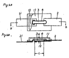
- Fig. 4A is a thin type thermal fuse according to a third embodiment of the present invention.
- Fig. 4B is a sectional view taken along a line B-B in Fig. 4A.
- This thin type thermal fuse also employs the cover film 12 formed by resin shown in Fig. 3.
- the thin type thermal fuse according to the third embodiment as shown in Fig. 4 is manufactured in the following manner.
- the tip portion of one belt-shaped lead conductor 21 is exposed from the rear surface side of the resin base film 11 to the main surface side thereof and then fixed on the main surface by the thermal pressing, or the like.
- the tip portion of the other belt-shaped lead conductor 2 is fixed on the main surface of the resin base film 11 by the thermal pressing, or the like.
- the low melting-point fusible alloy piece 3 is connected to the tip portions of the belt-shaped lead conductors 2, 21 by the resistor welding or the like so that the tip portions thereof are coupled by the low melting-point fusible alloy piece.
- the flux 4 is coated on the low melting-point fusible alloy piece 3.
- the resin cover film 12 having been formed in advance is disposed on the one surface of the resin base film 11. Then, the resin base film 11 is coupled to the peripheral portions of the resin cover film 12 and also the resin cover film 12 is coupled to the other belt-shaped lead conductor 2 by the heat sealing, ultrasonic fusing, laser radiation, or the like, whereby the fabrication of the thin type thermal fuse according to third embodiment is completed.
- the thin type thermal fuse satisfying the condition of (V/L) 1/2 /d ⁇ 1.8 can be easily manufactured by the normal manufacturing process.
- the thin type thermal fuse according to the present invention can be used in order to protect, for example, a lithium ion secondary battery from abnormal heating.
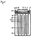
- Fig. 5 shows a lithium ion secondary battery which is arranged in the following manner. That is, a plurality of spirally-wound low melting-point fusible alloy pieces E each formed by a positive electrode 52, a negative electrode 53 and a separator 51 disposed between the positive and negative electrodes are housed within a negative electrode can 54 so that the negative electrode 53 is made electrically conductive with the bottom wall of the negative electrode can 54.
- a positive collecting electrode 55 is disposed at the top end within the negative electrode can 54 so that the positive electrode 52 is made electrically conductive with the positive collecting electrode 55.
- a top end portion 541 of the negative electrode can 54 is clamped at the outer peripheral end of an explosion-proof valve plate 56 and the outer peripheral end of a positive electrode lid 57 through a packing 58.
- the center concave portion of the explosion-proof valve plate 56 is made electrically conductive with a positive collecting electrode 59.
- the thin type thermal fuse manufactured according to the above embodiments can be used in the following manner. That is, the thin type thermal fuse is disposed in the space between the explosion-proof valve plate 56 and the positive electrode lid 57 of the lithium ion secondary battery. An insulation spacer ring r is disposed between the outer peripheral end of the explosion-proof valve plate 56 and the outer peripheral end of the positive electrode lid 57.
- One of the belt-shaped lead conductors 2 is sandwiched between the outer peripheral end of the explosion-proof valve plate 56 and the insulation spacer ring r, and the other of the belt-shaped lead conductors 2 is sandwiched between the outer peripheral end of the positive electrode lid 57 and the insulation spacer ring r, whereby the thin type thermal fuse is incorporated within the battery in series.
- Fig. 6A shows a thin type thermal fuse of a modification of the third embodiment.
- Fig. 6B is a sectional view taken along a line B-B in Fig. 6A.
- This thin type thermal fuse also can be used by being incorporated in series within the battery in the similar manner as described above.
- a symbol represents a frame wherein a film electrode fl having one belt-shaped lead conductor 21 at the inner periphery of an annular portion 201 shown in Fig. 7A, an annular resin spacer film s shown in Fig. 3B, and a film electrode f0 having the other belt-shaped lead conductor 2 at the inner periphery of an annular portion 200 shown in Fig. 7C are superimposed in a manner that the belt-shaped lead conductors 2, 21 are opposed with an angle of 180° therebetween.
- a hole a is formed at a sealed portion 20 of the lead conductor 2 of these two belt-shaped lead conductors 2, 21.
- These film electrodes f1, f0 may be combined with the surface of the resin spacer film s by the thermal fusing, or the like.
- a symbol A represents a thermal fuse body disposed in the center portion of the space of the frame F.
- This thermal fuse body is formed in the following manner. That is, the tip portion of the one belt-shaped lead conductor 21 is fixed on the one surface of the resin base film 11 and further locally exposed from the one surface of the resin base film 11 to the other surface thereof. The tip portion of the other belt-shaped lead conductor 2 is fixed on the other surface of the resin base film 11. The tip portion of the other belt-shaped lead conductor is coupled to the locally exposed tip portion of the one belt-shaped lead conductor 21 through the low melting-point fusible alloy piece 3 by the welding or the like so that the tip portions thereof are coupled by the low melting-point fusible alloy piece.
- the flux 4 is coated on the low melting-point fusible alloy piece 3.
- the resin cover film 12 shown in Fig. 3 is disposed on the flux-coated low melting-point fusible alloy piece.
- the resin base film 11 at the periphery of the resin cover film 12 is coupled to the resin cover film 12 and also the resin cover film 12 is coupled to the other belt-shaped lead conductor 2 by means of the heat sealing, ultrasonic fusing, laser radiation, or the like.
- the thin type thermal fuse is sandwiched in the battery shown in Fig. 5 between the outer peripheral end of the explosion-proof valve plate 56 and the outer peripheral end of the positive electrode lid 57 without disposing the spacer ring r therebetween, and the thin type thermal fuse is electrically connected in series to the battery through a path from the electrical contact between the explosion-proof valve plate 56 and the film electrode f1 of the frame F ⁇ the belt-shaped lead conductor 21 of the film electrode f1 ⁇ the low melting-point fusible alloy piece 3 ⁇ the belt-shaped lead conductor 2 of the film electrode f0 ⁇ the electrical contact between the positive electrode lid 57 and the film electrode f0 of the frame F.
- the thin type thermal fuse according to the present invention may also be used in the following manner. That is, the one belt-shaped lead conductor and the thermal fuse body are closely contacted to the negative electrode can of the battery, then the one belt-shaped lead conductor is electrically connected to the negative electrode can, and the other belt-shaped lead conductor is electrically insulated from the negative electrode can by separating the other belt-shaped lead conductor from the negative electrode can or disposing an insulation film therebetween.
- the thin type thermal fuse according to the present invention may be arranged in a manner that a slit(s) s is provided at the end portion(s) of the belt-shaped lead conductor(s), then the electrodes are abutted against the belt-shaped lead conductor(s) so as to sandwich the slit(s) of the lead conductor(s) therebetween, and the electrodes are coupled to the coupled surface (for example, the negative electrode can of the battery) by means of the resistor welding (the slit (s) serves to set the resistance value between the electrodes at a predetermined value).
- a hole e or a notch portion e' for positioning may be provided.
- the thin type thermal fuse satisfying the relation of (V / L) 1/2 / d ⁇ 1.8 can be manufactured by the normal manufacturing method, where the distance between the tip portions of the belt-shaped lead conductors is set to be L, the volume of the low melting-point fusible alloy piece is set to be V and the distance between the surface of the resin base film and the inner surface of the resin cover film is set to be d.
- the generation ratio of the inoperative thermal fuses can be substantially made zero so long as the aforesaid relation of (V/L) 1/2 /d ⁇ 1.8 is satisfied. Accordingly, according to the present invention, the thin type thermal fuse superior in the operability can be manufactured easily.
Landscapes
- Chemical & Material Sciences (AREA)
- Engineering & Computer Science (AREA)
- Combustion & Propulsion (AREA)
- Fuses (AREA)
Applications Claiming Priority (2)
| Application Number | Priority Date | Filing Date | Title |
|---|---|---|---|
| JP17967598A JP4396787B2 (ja) | 1998-06-11 | 1998-06-11 | 薄型温度ヒュ−ズ及び薄型温度ヒュ−ズの製造方法 |
| JP17967598 | 1998-06-11 |
Publications (2)
| Publication Number | Publication Date |
|---|---|
| EP0964419A1 true EP0964419A1 (de) | 1999-12-15 |
| EP0964419B1 EP0964419B1 (de) | 2005-05-11 |
Family
ID=16069918
Family Applications (1)
| Application Number | Title | Priority Date | Filing Date |
|---|---|---|---|
| EP99301462A Expired - Lifetime EP0964419B1 (de) | 1998-06-11 | 1999-02-26 | Flache thermische Sicherung und Herstellungsverfahren |
Country Status (5)
| Country | Link |
|---|---|
| US (1) | US6040754A (de) |
| EP (1) | EP0964419B1 (de) |
| JP (1) | JP4396787B2 (de) |
| KR (1) | KR100347232B1 (de) |
| DE (1) | DE69925198T2 (de) |
Cited By (7)
| Publication number | Priority date | Publication date | Assignee | Title |
|---|---|---|---|---|
| DE10058973A1 (de) * | 2000-11-28 | 2002-05-29 | Rolls Royce Deutschland | Permanentmagnet-Maschine sowie Sicherungseinrichtung hierfür |
| US6556122B2 (en) | 2000-07-21 | 2003-04-29 | Matsushita Electric Industrial Co., Ltd. | Thermal fuse, battery pack, and method of manufacturing thermal fuse |
| WO2005004183A1 (en) * | 2003-07-01 | 2005-01-13 | Matsushita Electric Industrial Co., Ltd. | Fuse, battery pack using the fuse, and method of manufacturing the fuse |
| EP1357569A4 (de) * | 2001-02-20 | 2005-03-02 | Matsushita Electric Industrial Co Ltd | Thermische sicherung |
| EP2587567A1 (de) * | 2011-10-25 | 2013-05-01 | Samsung SDI Co., Ltd. | Wiederaufladbare Batterie |
| EP2662913A4 (de) * | 2011-11-28 | 2015-04-15 | Lg Chemical Ltd | Batteriemodul und sammelschiene für das batteriemodul |
| EP4087050A4 (de) * | 2019-12-30 | 2024-05-29 | Hefei Gotion High-Tech Power Energy Co., Ltd. | Integrierter hochtemperaturzersetzbarer verbinder und lithium-ionenbatterie damit |
Families Citing this family (30)
| Publication number | Priority date | Publication date | Assignee | Title |
|---|---|---|---|---|
| US6057779A (en) * | 1997-08-14 | 2000-05-02 | Micron Technology, Inc. | Method of controlling access to a movable container and to a compartment of a vehicle, and a secure cargo transportation system |
| DE19738575A1 (de) * | 1997-09-04 | 1999-06-10 | Wickmann Werke Gmbh | Elektrisches Sicherungselement |
| FR2821983B1 (fr) * | 2001-03-07 | 2003-08-15 | Schneider Electric Ind Sa | Dispositif de raccordement pour accumulateur electrique |
| CN100492574C (zh) * | 2001-06-05 | 2009-05-27 | 松下电器产业株式会社 | 温度熔断器和使用它的电池 |
| CN1327467C (zh) * | 2001-06-11 | 2007-07-18 | 维克曼工厂有限公司 | 熔断器件及其制造方法 |
| KR100776875B1 (ko) * | 2002-10-07 | 2007-11-16 | 마쯔시다덴기산교 가부시키가이샤 | 온도 퓨즈용 소자, 온도 퓨즈 및 이를 이용한 전지 |
| US20040119578A1 (en) * | 2002-12-20 | 2004-06-24 | Ching-Lung Tseng | Packaging structure for an electronic element |
| JP2004214033A (ja) * | 2002-12-27 | 2004-07-29 | Sony Chem Corp | 保護素子 |
| JP2004265618A (ja) | 2003-02-05 | 2004-09-24 | Sony Chem Corp | 保護素子 |
| JP4223316B2 (ja) * | 2003-04-03 | 2009-02-12 | 内橋エステック株式会社 | 二次電池用ヒューズ |
| CN100376704C (zh) * | 2003-05-29 | 2008-03-26 | 松下电器产业株式会社 | 温度保险丝用元件、温度保险丝及使用了温度保险丝的电池 |
| WO2005006374A2 (en) * | 2003-07-11 | 2005-01-20 | Matsushita Electric Industrial Co., Ltd. | Fusible alloy and thermal fuse |
| DE10355282A1 (de) * | 2003-11-18 | 2005-06-16 | E.G.O. Elektro-Gerätebau GmbH | Verfahren zur Herstellung einer Übertemperatursicherung und Übertemperatursicherung |
| DE102004033251B3 (de) | 2004-07-08 | 2006-03-09 | Vishay Bccomponents Beyschlag Gmbh | Schmelzsicherung für einem Chip |
| US7477130B2 (en) * | 2005-01-28 | 2009-01-13 | Littelfuse, Inc. | Dual fuse link thin film fuse |
| EP1908154A2 (de) * | 2005-07-22 | 2008-04-09 | Littelfuse, Inc. | Elektrisches gerät mit schmelzleiter |
| US20070075822A1 (en) * | 2005-10-03 | 2007-04-05 | Littlefuse, Inc. | Fuse with cavity forming enclosure |
| TWI323906B (en) * | 2007-02-14 | 2010-04-21 | Besdon Technology Corp | Chip-type fuse and method of manufacturing the same |
| DE102007014338A1 (de) * | 2007-03-26 | 2008-10-02 | Robert Bosch Gmbh | Thermosicherung |
| CN101393823B (zh) * | 2007-09-21 | 2010-12-22 | 比亚迪股份有限公司 | 一种合金型温度保险丝及其制造方法 |
| JP5287154B2 (ja) * | 2007-11-08 | 2013-09-11 | パナソニック株式会社 | 回路保護素子およびその製造方法 |
| US8525633B2 (en) * | 2008-04-21 | 2013-09-03 | Littelfuse, Inc. | Fusible substrate |
| JP5072796B2 (ja) * | 2008-05-23 | 2012-11-14 | ソニーケミカル&インフォメーションデバイス株式会社 | 保護素子及び二次電池装置 |
| US20110163840A1 (en) * | 2008-10-28 | 2011-07-07 | Nanjing Sart Science & Technology Development Co., Ltd. | High reliability blade fuse and the manufacturing method thereof |
| JP5130233B2 (ja) * | 2009-01-21 | 2013-01-30 | デクセリアルズ株式会社 | 保護素子 |
| JP5130232B2 (ja) | 2009-01-21 | 2013-01-30 | デクセリアルズ株式会社 | 保護素子 |
| JP5301298B2 (ja) * | 2009-01-21 | 2013-09-25 | デクセリアルズ株式会社 | 保護素子 |
| KR101279994B1 (ko) * | 2010-10-15 | 2013-07-05 | 주식회사 엘지화학 | 전극리드에 안전부재가 위치한 구조의 캡 어셈블리 및 이를 포함하고 있는 원통형 전지 |
| JP5844669B2 (ja) * | 2012-03-26 | 2016-01-20 | デクセリアルズ株式会社 | 保護素子 |
| JP6382028B2 (ja) * | 2014-08-26 | 2018-08-29 | デクセリアルズ株式会社 | 回路基板及び電子部品の実装方法 |
Citations (5)
| Publication number | Priority date | Publication date | Assignee | Title |
|---|---|---|---|---|
| FR2134341A1 (de) * | 1971-04-29 | 1972-12-08 | Bosch | |
| JPH02291624A (ja) * | 1989-02-27 | 1990-12-03 | Uchihashi Estec Co Ltd | 薄形ヒューズ |
| JPH042023A (ja) * | 1990-02-01 | 1992-01-07 | Uchihashi Estec Co Ltd | 抵抗・温度ヒューズ並びにその製造方法 |
| JPH1012111A (ja) * | 1996-06-18 | 1998-01-16 | Uchihashi Estec Co Ltd | 合金型温度ヒュ−ズ及びその製造方法 |
| JPH10106425A (ja) * | 1996-10-01 | 1998-04-24 | Uchihashi Estec Co Ltd | 薄型ヒュ−ズ |
Family Cites Families (24)
| Publication number | Priority date | Publication date | Assignee | Title |
|---|---|---|---|---|
| US3805208A (en) * | 1973-06-14 | 1974-04-16 | Alister C Mc | Protector for electric circuits |
| US4272753A (en) * | 1978-08-16 | 1981-06-09 | Harris Corporation | Integrated circuit fuse |
| JPS56160648A (en) * | 1980-05-14 | 1981-12-10 | Fuji Electric Co Ltd | Oxygen sensor |
| JPS57117255A (en) * | 1981-01-12 | 1982-07-21 | Toshiba Corp | Semiconductor ic device |
| JPS57122565A (en) * | 1981-01-22 | 1982-07-30 | Toshiba Corp | Semiconductor device |
| US4626818A (en) * | 1983-11-28 | 1986-12-02 | Centralab, Inc. | Device for programmable thick film networks |
| US4924203A (en) * | 1987-03-24 | 1990-05-08 | Cooper Industries, Inc. | Wire bonded microfuse and method of making |
| US4873506A (en) * | 1988-03-09 | 1989-10-10 | Cooper Industries, Inc. | Metallo-organic film fractional ampere fuses and method of making |
| JPH01272133A (ja) * | 1988-04-22 | 1989-10-31 | Mitsubishi Electric Corp | 半導体装置 |
| JPH01295440A (ja) * | 1988-05-24 | 1989-11-29 | Nissan Motor Co Ltd | 半導体装置 |
| JPH02100221A (ja) * | 1988-10-07 | 1990-04-12 | Fujikura Ltd | 温度ヒューズおよびその形成方法 |
| CH682959A5 (fr) * | 1990-05-04 | 1993-12-15 | Battelle Memorial Institute | Fusible. |
| JPH0465046A (ja) * | 1990-07-02 | 1992-03-02 | Tateyama Kagaku Kogyo Kk | チップ形ヒューズ抵抗器 |
| US5099219A (en) * | 1991-02-28 | 1992-03-24 | Rock, Ltd. Partnership | Fusible flexible printed circuit and method of making same |
| US5097247A (en) * | 1991-06-03 | 1992-03-17 | North American Philips Corporation | Heat actuated fuse apparatus with solder link |
| JPH04365351A (ja) * | 1991-06-13 | 1992-12-17 | Nec Corp | 半導体集積回路装置 |
| DE4222278C1 (de) * | 1992-07-07 | 1994-03-31 | Roederstein Kondensatoren | Verfahren zur Herstellung elektrischer Dickschichtsicherungen |
| JP2624439B2 (ja) * | 1993-04-30 | 1997-06-25 | コーア株式会社 | 回路保護用素子 |
| US5432378A (en) * | 1993-12-15 | 1995-07-11 | Cooper Industries, Inc. | Subminiature surface mounted circuit protector |
| US5453726A (en) * | 1993-12-29 | 1995-09-26 | Aem (Holdings), Inc. | High reliability thick film surface mount fuse assembly |
| US5552757A (en) * | 1994-05-27 | 1996-09-03 | Littelfuse, Inc. | Surface-mounted fuse device |
| US5712610C1 (en) * | 1994-08-19 | 2002-06-25 | Sony Chemicals Corp | Protective device |
| JP2670756B2 (ja) * | 1995-02-02 | 1997-10-29 | 釜屋電機株式会社 | チップ形ヒューズ抵抗器、及びその製造方法 |
| JP3774871B2 (ja) * | 1995-10-16 | 2006-05-17 | 松尾電機株式会社 | 遅延型薄膜ヒューズ |
-
1998
- 1998-06-11 JP JP17967598A patent/JP4396787B2/ja not_active Expired - Fee Related
-
1999
- 1999-02-08 KR KR1019990004197A patent/KR100347232B1/ko not_active Expired - Fee Related
- 1999-02-26 EP EP99301462A patent/EP0964419B1/de not_active Expired - Lifetime
- 1999-02-26 US US09/258,255 patent/US6040754A/en not_active Expired - Fee Related
- 1999-02-26 DE DE69925198T patent/DE69925198T2/de not_active Expired - Lifetime
Patent Citations (5)
| Publication number | Priority date | Publication date | Assignee | Title |
|---|---|---|---|---|
| FR2134341A1 (de) * | 1971-04-29 | 1972-12-08 | Bosch | |
| JPH02291624A (ja) * | 1989-02-27 | 1990-12-03 | Uchihashi Estec Co Ltd | 薄形ヒューズ |
| JPH042023A (ja) * | 1990-02-01 | 1992-01-07 | Uchihashi Estec Co Ltd | 抵抗・温度ヒューズ並びにその製造方法 |
| JPH1012111A (ja) * | 1996-06-18 | 1998-01-16 | Uchihashi Estec Co Ltd | 合金型温度ヒュ−ズ及びその製造方法 |
| JPH10106425A (ja) * | 1996-10-01 | 1998-04-24 | Uchihashi Estec Co Ltd | 薄型ヒュ−ズ |
Non-Patent Citations (4)
| Title |
|---|
| PATENT ABSTRACTS OF JAPAN vol. 015, no. 070 (E - 1035) 19 February 1991 (1991-02-19) * |
| PATENT ABSTRACTS OF JAPAN vol. 016, no. 142 (E - 1187) 9 April 1992 (1992-04-09) * |
| PATENT ABSTRACTS OF JAPAN vol. 098, no. 005 30 April 1998 (1998-04-30) * |
| PATENT ABSTRACTS OF JAPAN vol. 098, no. 009 31 July 1998 (1998-07-31) * |
Cited By (13)
| Publication number | Priority date | Publication date | Assignee | Title |
|---|---|---|---|---|
| US6556122B2 (en) | 2000-07-21 | 2003-04-29 | Matsushita Electric Industrial Co., Ltd. | Thermal fuse, battery pack, and method of manufacturing thermal fuse |
| DE10135256B4 (de) * | 2000-07-21 | 2004-02-26 | Matsushita Electric Industrial Co. Ltd. | Thermische Sicherung und Verfahren zur Herstellung der Thermischen Sicherung |
| DE10135256B8 (de) * | 2000-07-21 | 2004-06-09 | Matsushita Electric Industrial Co. Ltd. | Thermische Sicherung und Verfahren zur Herstellung der Thermischen Sicherung |
| DE10058973A1 (de) * | 2000-11-28 | 2002-05-29 | Rolls Royce Deutschland | Permanentmagnet-Maschine sowie Sicherungseinrichtung hierfür |
| US7068141B2 (en) | 2001-02-20 | 2006-06-27 | Matsushita Electric Industrial Co., Ltd. | Thermal fuse |
| EP1357569A4 (de) * | 2001-02-20 | 2005-03-02 | Matsushita Electric Industrial Co Ltd | Thermische sicherung |
| WO2005004183A1 (en) * | 2003-07-01 | 2005-01-13 | Matsushita Electric Industrial Co., Ltd. | Fuse, battery pack using the fuse, and method of manufacturing the fuse |
| US7106165B2 (en) | 2003-07-01 | 2006-09-12 | Matsushita Electric Industrial Co., Ltd. | Fuse, battery pack using the fuse, and method of manufacturing the fuse |
| EP2587567A1 (de) * | 2011-10-25 | 2013-05-01 | Samsung SDI Co., Ltd. | Wiederaufladbare Batterie |
| US9209449B2 (en) | 2011-10-25 | 2015-12-08 | Samsung Sdi Co., Ltd. | Rechargeable battery with fuse part and auxiliary discharge path |
| EP2662913A4 (de) * | 2011-11-28 | 2015-04-15 | Lg Chemical Ltd | Batteriemodul und sammelschiene für das batteriemodul |
| US9577240B2 (en) | 2011-11-28 | 2017-02-21 | Lg Chem, Ltd. | Battery module and bus bar applied to battery module |
| EP4087050A4 (de) * | 2019-12-30 | 2024-05-29 | Hefei Gotion High-Tech Power Energy Co., Ltd. | Integrierter hochtemperaturzersetzbarer verbinder und lithium-ionenbatterie damit |
Also Published As
| Publication number | Publication date |
|---|---|
| KR100347232B1 (ko) | 2002-08-01 |
| JPH11353996A (ja) | 1999-12-24 |
| KR20000005584A (ko) | 2000-01-25 |
| EP0964419B1 (de) | 2005-05-11 |
| US6040754A (en) | 2000-03-21 |
| DE69925198T2 (de) | 2005-11-17 |
| DE69925198D1 (de) | 2005-06-16 |
| JP4396787B2 (ja) | 2010-01-13 |
Similar Documents
| Publication | Publication Date | Title |
|---|---|---|
| EP0964419B1 (de) | Flache thermische Sicherung und Herstellungsverfahren | |
| US7474076B2 (en) | Secondary battery with positive temperature coefficient (PTC) safety element | |
| WO2000011737A1 (en) | Secondary battery | |
| US7718308B2 (en) | Temperature fuse and battery using the same | |
| KR19990036224A (ko) | Ptc 소자 및 그것을 이용한 전지 조립체 | |
| CN100474663C (zh) | 可再充电电池 | |
| US10283295B2 (en) | Protection device | |
| JP3154279B2 (ja) | 二次電池 | |
| JPWO1997006538A1 (ja) | Ptc素子およびそれを用いた電池組立体 | |
| KR20090012359A (ko) | 보호 소자 | |
| CN109565024B (zh) | 电池模块 | |
| KR20010075545A (ko) | 전도성 폴리머 ptc 배터리 보호 장치 및 그 제조 방법 | |
| JP3618635B2 (ja) | 電池用プロテクタ− | |
| EP1368843B1 (de) | Anschlussvorrichtung für elektrischen akkumulator | |
| JPH10188947A (ja) | 電池および電池用保護素子 | |
| JP2006221919A (ja) | 基板型抵抗体付きヒューズ及び電池パック | |
| JP2003022798A (ja) | リンクヒューズ | |
| JP3754794B2 (ja) | 温度ヒュ−ズ及び二次電池における温度ヒュ−ズの取付け構造 | |
| JP2008016190A (ja) | パック電池 | |
| JP4097790B2 (ja) | 薄型温度ヒュ−ズ | |
| JP3878733B2 (ja) | 電池における温度ヒュ−ズの内付け構造及び温度ヒュ−ズ | |
| JP3866366B2 (ja) | 回路保護素子の製造方法 | |
| JP3478816B2 (ja) | 温度ヒューズ及びパック電池 | |
| JPH11204006A (ja) | 温度ヒュ−ズ | |
| JP2004014224A (ja) | 電流ヒューズ機能付温度ヒューズ |
Legal Events
| Date | Code | Title | Description |
|---|---|---|---|
| PUAI | Public reference made under article 153(3) epc to a published international application that has entered the european phase |
Free format text: ORIGINAL CODE: 0009012 |
|
| AK | Designated contracting states |
Kind code of ref document: A1 Designated state(s): DE FI FR GB SE |
|
| AX | Request for extension of the european patent |
Free format text: AL;LT;LV;MK;RO;SI |
|
| 17P | Request for examination filed |
Effective date: 20000417 |
|
| AKX | Designation fees paid |
Free format text: DE FI FR GB SE |
|
| GRAP | Despatch of communication of intention to grant a patent |
Free format text: ORIGINAL CODE: EPIDOSNIGR1 |
|
| GRAS | Grant fee paid |
Free format text: ORIGINAL CODE: EPIDOSNIGR3 |
|
| GRAA | (expected) grant |
Free format text: ORIGINAL CODE: 0009210 |
|
| RIN1 | Information on inventor provided before grant (corrected) |
Inventor name: KAWANISHI, TOSHIRO,UCHIHASHI ESTEC CO., LTD. |
|
| AK | Designated contracting states |
Kind code of ref document: B1 Designated state(s): DE FI FR GB SE |
|
| REG | Reference to a national code |
Ref country code: GB Ref legal event code: FG4D |
|
| REG | Reference to a national code |
Ref country code: SE Ref legal event code: TRGR |
|
| REF | Corresponds to: |
Ref document number: 69925198 Country of ref document: DE Date of ref document: 20050616 Kind code of ref document: P |
|
| ET | Fr: translation filed | ||
| PLBE | No opposition filed within time limit |
Free format text: ORIGINAL CODE: 0009261 |
|
| STAA | Information on the status of an ep patent application or granted ep patent |
Free format text: STATUS: NO OPPOSITION FILED WITHIN TIME LIMIT |
|
| 26N | No opposition filed |
Effective date: 20060214 |
|
| PGFP | Annual fee paid to national office [announced via postgrant information from national office to epo] |
Ref country code: SE Payment date: 20110211 Year of fee payment: 13 Ref country code: FI Payment date: 20110211 Year of fee payment: 13 |
|
| PG25 | Lapsed in a contracting state [announced via postgrant information from national office to epo] |
Ref country code: FI Free format text: LAPSE BECAUSE OF NON-PAYMENT OF DUE FEES Effective date: 20120226 Ref country code: SE Free format text: LAPSE BECAUSE OF NON-PAYMENT OF DUE FEES Effective date: 20120227 |
|
| PGFP | Annual fee paid to national office [announced via postgrant information from national office to epo] |
Ref country code: FR Payment date: 20140211 Year of fee payment: 16 |
|
| PGFP | Annual fee paid to national office [announced via postgrant information from national office to epo] |
Ref country code: GB Payment date: 20140226 Year of fee payment: 16 |
|
| PGFP | Annual fee paid to national office [announced via postgrant information from national office to epo] |
Ref country code: DE Payment date: 20140417 Year of fee payment: 16 |
|
| REG | Reference to a national code |
Ref country code: DE Ref legal event code: R119 Ref document number: 69925198 Country of ref document: DE |
|
| GBPC | Gb: european patent ceased through non-payment of renewal fee |
Effective date: 20150226 |
|
| REG | Reference to a national code |
Ref country code: FR Ref legal event code: ST Effective date: 20151030 |
|
| PG25 | Lapsed in a contracting state [announced via postgrant information from national office to epo] |
Ref country code: GB Free format text: LAPSE BECAUSE OF NON-PAYMENT OF DUE FEES Effective date: 20150226 Ref country code: DE Free format text: LAPSE BECAUSE OF NON-PAYMENT OF DUE FEES Effective date: 20150901 |
|
| PG25 | Lapsed in a contracting state [announced via postgrant information from national office to epo] |
Ref country code: FR Free format text: LAPSE BECAUSE OF NON-PAYMENT OF DUE FEES Effective date: 20150302 |