EP0973025B1 - Instrument de mesure d'orientations - Google Patents
Instrument de mesure d'orientations Download PDFInfo
- Publication number
- EP0973025B1 EP0973025B1 EP98911025A EP98911025A EP0973025B1 EP 0973025 B1 EP0973025 B1 EP 0973025B1 EP 98911025 A EP98911025 A EP 98911025A EP 98911025 A EP98911025 A EP 98911025A EP 0973025 B1 EP0973025 B1 EP 0973025B1
- Authority
- EP
- European Patent Office
- Prior art keywords
- sample
- dielectric resonator
- dielectric
- resonator
- plane
- Prior art date
- Legal status (The legal status is an assumption and is not a legal conclusion. Google has not performed a legal analysis and makes no representation as to the accuracy of the status listed.)
- Expired - Lifetime
Links
- 0 CC[C@]1(C(C2)C3(**C*3)[C@](C)(*3(C)*C3)C(CC)(CC=N*=CC)C3)[C@]4C5(C6)C7ICC5CC6C4C3(CCC(C)(CCC3(*)CC3)CC3)C73C(CCC*)[C@]2(C*)[C@@]1C Chemical compound CC[C@]1(C(C2)C3(**C*3)[C@](C)(*3(C)*C3)C(CC)(CC=N*=CC)C3)[C@]4C5(C6)C7ICC5CC6C4C3(CCC(C)(CCC3(*)CC3)CC3)C73C(CCC*)[C@]2(C*)[C@@]1C 0.000 description 2
Images


Classifications
-
- G—PHYSICS
- G01—MEASURING; TESTING
- G01N—INVESTIGATING OR ANALYSING MATERIALS BY DETERMINING THEIR CHEMICAL OR PHYSICAL PROPERTIES
- G01N22/00—Investigating or analysing materials by the use of microwaves or radio waves, i.e. electromagnetic waves with a wavelength of one millimetre or more
Definitions
- the present invention relates to an instrument measuring the orientation of those inclusive of sheet-like substances such as a polymer sheet including a film and paper and stereoscopic articles such as moldings of plastic, resin, rubber and the like with a microwave.
- the fiber orientation of paper corresponds to the chain direction of molecules forming fiber, and is closely related with curling, torsion, inclination of NIP (Non-Impact Printer) paper and the like.
- Standards in fiber orientation are becoming strict particularly in these several years, and several types of measuring methods have been employed. There are a water diffusion method, a dynamic rupture intensity method, an ultrasonic method, a microwave method and the like as such measuring methods, and the correspondence between operations on a wire part and the orientation is substantially being elucidated at present.
- anisotropy of the arrangement of molecular chains can be grasped as the anisotropy of various physical properties, for example, optical, electrical and mechanical intensity and the like. Therefore, inclusive of paper, polymer film and the like, the orientation can be collectively grasped as the anisotropy (molecular orientation) of the arrangement of molecular chains.
- a solid polymer has orientation in the process where molecular chains are solidified from a fluidized state due to the shape thereof. Due to the orientation, anisotropy appears in a dynamic, thermal, optical or electromagnetic physical property. Consequently, for example, anisotropy of the modulus of elasticity, anisotropy of the ratio of heat contraction or the like, takes place to cause various problems in quality.
- an X-ray diffraction method As methods of measuring such anisotropy, an X-ray diffraction method, an infrared polarization method, a fluorescence polarization method, a birefringence method, an ultrasonic method, a microwave method and the like are employed.
- the X-ray diffraction method and the fluorescence polarization method require time and labor for measurement, while measurement is difficult in relation to a thick sample in the infrared polarization method.
- the birefringence method is a method of optically measuring anisotropy by utilizing a refraction phenomenon based on anisotropy of a refraction index, and an opaque sample cannot be measured since transparency with respect to visible light or near infrared light is required for measurement.
- the ultrasonic method is of a contact type and hence unsuitable for a moving sample.
- a method employing resonance of a microwave utilizes anisotropy of a dielectric constant.
- the dielectric constant has a constant relation also with a refractive index.
- the method employing a microwave is utilized for molecular orientation measurement regardless of presence/absence of optical transparency inclusive of paper and a polymer film.
- Fig. 1 illustrates the principle of a conventional orientation meter employing a microwave cavity resonator such conventional methods are known from, e.g., US 5,532,604 A and JP-07-103 917 A. It comprises a microwave introduction part 2 on one end portion and a microwave detection part 4 on another end portion. The part between these end portions defines a microwave resonator 6 formed by a waveguide having a constant electric field vibrational direction. The resonator 6 is provided with a slit 8 in a direction perpendicularly crossing the axis of the resonator 6 on the position of a loop part of a standing wave.
- a sample 10 is arranged in the slit 8, a microwave is introduced from the microwave introduction part 2, and the microwave intensity is detected with the microwave detection part 4.
- the sample 10 is rotated around the axis of the resonator 6, and the intensity of the transmitted microwave is detected every rotational angle for obtaining the orientation pattern. It is also possible to obtain a dielectric constant pattern by obtaining the dielectric constant every rotational angle position from deviation between the resonance frequency when arranging the sample 10 in the slit 10 and the resonance frequency when arranging no sample.
- Fig. 2 As a method of measuring the dielectric constant with a microwave, that shown in Fig. 2 is proposed (refer to Japanese Utility Model Laying-Open Gazette Jitsu Kai Hei 3-70368). There, it comprises a pair of dielectric resonators 12a and 12b opposite to each other through a sample 10. A pair of terminals 14a and 14b oppositely arranged through the dielectric resonator 12a are provided on side portions of one dielectric resonator 12a. An electric field vector having one direction parallel to the plane of the sample 10 is generated in the dielectric resonators 12a and 12b by these terminals 14a and 14b, for measuring the dielectric constant from the resonance characteristics thereof.
- the terminals 14a and 14b are loop-like. It is also possible to comprise a plurality of pairs of terminals 14a and 14b and measure dielectric anisotropy of the sample by switching operations thereof.
- cavity resonators or dielectric resonators are oppositely arranged on both sides through the sample 10, and hence the shape of the measured sample 10 is limited to a sheet-like one.
- WO 97/01088 A1 describes the for determination of orientation of fibers in a material such as a paper or paperboard web comprised of elongated fibers of high moisture content.
- the material is subjected to an alternating electric field of the RF or microwave frequency range lying in the plane of the material and the change caused by the presence of said material in said alternating electric field is measured.
- the direction of said alternating electric field is altered during the measurement, whereby the material need not be rotated with respect to the resonator for the measurement.
- US 4,904,928 A describes a measurement apparatus utilizing microwave energy.
- a symmetric microwave cavity is excited to oscillate in at least two identical resonant modes having substantially the same resonant frequencies but different field orientations relative to each other.
- a sample to be measured is caused to interact with the identical resonant modes and the difference in the frequencies of oscillation of the modes is determined in order to measure a property of the sample.
- JP 07-270342 A describes measuring the orientation of molecules of a running sheet online.
- a plurality of microwave beams parallel to each other and showing different oscillation directions of an electromagnetic field are cast on a sample, and the intensity of each passing beam is detected.
- An orientation pattern is derived from the detected outputs.
- a plurality of waveguides are arranged to be adjacent to each other with axes made parallel to each other while oscillation directions of an electric field are made different.
- a slit for setting the sample thereon is provided in each waveguide in a manner to traverse the axis. The slits of all the waveguides are within the same plane.
- a transmittance of each microwave is measured.
- JP 08-271449 A describes an on-line measurement of the molecular orientation of a paper or high polymer continuous sheet being carried on a line.
- a microwave oscillator is connected with at least three waveguides through an attenuator.
- the waveguide is provided with a slit.
- a sample is carried in a predetermined direction while passing the slit.
- the waveguides are arranged such that the field vectors of microwave are directed at different angles from each other.
- Each pair of waveguide parts can move relatively in the axial direction.
- Each waveguide is internally provided with an iris.
- Output from a microwave intensity detecting section is delivered through an amplifier and an A/D converter to an operating section. The operating section determines a molecular orientation pattern based on the detection data and outputs an orientation and orientation angle.
- EP 0 547 968 A1 describes a system which comprises a dielectric resonator, whose two opposite faces and the face joining these faces are conductive.
- the system also comprises means for exciting the resonator and detecting a signal output by the excited resonator, means for controlling this excitation and measuring the resonant frequency and the quality factor of the resonator using this signal, a conducting casing, one face of which is open and placed facing the material investigated, and in which are placed the resonator and the excitation and detection means, which makes it possibleto determine two of the parameters of the material, given the others.
- the electric field vector in an in-sample plane is more uniform during measuring the dielectric anisotropy.
- the terminals 14a and 14b are loop-like in the measuring instrument shown in Fig 2
- the bar-like terminal shape attains uniformity of an electric field vector further than the loop-like terminal and improves the sensitivity of dielectric anisotropy measurement.
- One aspect of the present invention comprises an orientation measuring instrument as defined in claim 1.
- This aspect is suitable for obtaining the dielectric anisotropy of a specific part of the sample.
- Another aspect of the present invention comprises an orientation measuring instrument as defined in claim 2.
- neither the sample nor the dielectric resonators may be rotated but the dielectric anisotropy of the sample can be obtained by outputs from the plurality of dielectric resonators, whereby it is suitable for continuously measuring a sample flowing online.
- Still another aspect of the present invention comprises an orientation measuring instrument as defined in claim 3.
- neither the sample nor the dielectric resonator may be rotated but the dielectric anisotropy of the sample can be obtained by switching operations of the sets of the microwave exciters and the detectors by the switching driver, whereby it is suitable for continuously measuring a sample flowing online also in this case.
- Variance of the detection output by the detector can be measured as variance of the resonance frequency.
- the variance of the resonance frequency can be measured as the shift quantity of the frequency itself.
- Terminals of the microwave exciter and the detector are rendered rod-like terminals.
- Electric field distribution on the position of the sample is decided by a resonance mode determined by the shape, the magnitude, an excitation method, the dielectric constant etc. of the dielectric resonator, and hence it is desirable to select such a resonance mode that an electric field as parallel as possible to the plane being close to or being in contact with the sample is produced.
- the rod-like terminals may be so arranged that the directions of magnetic field distribution or electric field distribution in the resonance mode to be resonated and the magnetic field or the electric field produced by the rod-like terminals vectorially coincide with each other, and are preferably arranged in the vicinity of or inside the dielectric resonator.
- the rod-like terminals are arranged in a direction perpendicular to the plane of the dielectric resonator being close to or being in contact with the sample.
- the exciter and the detector are connected respectively to a pair of rod-like terminals oppositely arranged through the dielectric resonator.
- the exciter and the detector are connected to one common rod-like terminal arranged close to the dielectric resonator.
- the dielectric resonator is a cylindrical resonator or a square resonator.
- the periphery of the dielectric resonator is preferably covered with a shielding material consisting of a conductive material except a sample measuring surface.
- a shielding material consisting of a conductive material is arranged also above a sample measuring surface of the dielectric resonator so that the sample is arranged between the sample measuring surface of the dielectric resonator and the shielding material above the sample measuring surface.
- Fig. 3(A) schematically shows one device which does not lie within the scope of the claims.
- a dielectric resonator 20 proper microwave loop antennas (or rod antennas) 22a and 22b are arranged on proper positions in proper directions with respect to the dielectric resonator 20. It is possible to produce a resonance mode resonating the dielectric resonator 20, where an electric field vector leaking outward from the resonator 20 is present, by the antennas 22a and 22b.
- resonance modes there is a TM mode or a TE mode when the dielectric resonator 20 is square, and there is an HEM mode or the like when it is cylindrical.
- the intensity of an electric field vector 24 substantially exponentially decreases as separating from the dielectric resonator 20, while the resonance frequency shifts by electromagnetic coupling in response to the dielectric constant of a sample by placing the sample 25 in separation from the dielectric resonator 20 by a small distance or in contact with the dielectric resonator 20.
- Fig. 3(A) schematically shows the structure in the case of employing a cylindrical dielectric resonator as the dielectric resonator 20 and making an HEM 11 ⁇ mode, while a microwave going out from an oscillator 26 generates an electric field through the loop antenna 22a, and the dielectric resonator 20 resonates by electromagnetic coupling.
- Fig. 3(B) expresses Fig. 3(A) as an equivalent circuit.
- the resonance frequency shifts by the capacitance Cr changing in response to the dielectric constant of the sample 25 when placing the sample 25.
- the resonance frequency also shifts with depending on the directions of the sample 25 and the electric field vector 24.
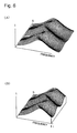
- Fig. 4 shows electric field distribution in the HEM 11 ⁇ mode.
- A shows electric field distribution on a horizontal plane around an end of the dielectric resonator 20, and
- the microwave going out from the oscillator 26 is magnetically coupled with the dielectric resonator 20 by the loop antenna 22a, and the dielectric resonator 20 can enter a resonant state.
- the electric field vector of the dielectric resonator 20 appears in the form substantially parallel to the plane of the sample 25, and interaction with a dipole moment provided in the sample 25 takes place.
- the orientation state can be obtained from angle dependency of the intensity.
- a controller 30 controls the frequency of the microwave generated from the oscillator 26 and captures the microwave intensity by the detector 28.
- 32 is a computer as a data processor obtaining the orientation state from the angle dependency of the detected microwave intensity.
- Fig. 5(A) the intensity of the transmitted microwave and the frequency.
- This resonance curve is referred to as a Q curve.
- 2 d v ⁇ 2 ⁇ f
- the detected intensity of the transmitted microwave at each rotational angle at the frequency f 1 is shown as a section of Fig. 6(B). Rewriting it with the rotational angle S on the horizontal axis, it becomes as shown in Fig. 7(A). Further rewriting it in a spherical coordinate system, it becomes elliptic as shown in Fig. 7(B), and the orientation angle ( ⁇ ) and the degree of orientation (a/b) can be obtained from this result a is the major axis length of the elliptic, and b is the minor axis length.
- the present invention comprises a dielectric resonator having a plane being close to or being in contact with a sample, and rotates the sample or the dielectric resonator in the plane or changes the direction of an electric field vector while generating the electric field vector having a unidirectional component at a frequency in the vicinity of the resonance frequency of the dielectric resonator when the sample is present and in an in-sample plane parallel to the plane.
- it comprises a plurality of dielectric resonators having planes being close to or being in contact with a sample and arranged close to each other, and generates electric field vectors having unidirectional components which are electric field vectors having directions different from each other at a frequency in the vicinity of the resonance frequency of the dielectric resonators when the sample is present and in in-sample planes parallel to the planes in the respective dielectric resonators. Then, it obtains dielectric anisotropy of the sample from variance of a detection value of resonance energy following rotation of the sample or the dielectric resonators or change of the electric field vectors or detection values of resonance energy from the plurality of dielectric resonators having different directions of electric field vectors.
- dielectric anisotropy not only in the case where the shape of the sample is a sheet-like one but also in a sample such as a stereoscopic molding.
- a moving sample can be continuously measured by rotating the dielectric resonator, changing the direction of the electric field vector or arranging a plurality of dielectric resonators having different directions of electric field vectors, so that it is applicable to online measurement on the production site.
- the dielectric resonator when covered with a conductive shielding member except a part where the sample is arranged, Q of a resonance spectrum increases and measurement with a considerate S/N ratio is enabled.
- Fig. 8 shows a device, which does not lie within the scope of the claims.
- a discharge polyethylene molding is put as a supporter 38 of a low dielectric constant in a cylindrical shield case 35 of brass whose upper part has an opening, and a cylindrical dielectric resonator 20 is mounted on the supporter 38 with the bottom surface in the horizontal direction.
- the dielectric resonator 20 its upper surface is set substantially flush with an edge of the opening of the shield case 35, and a sample is placed on the opening part of the shield case 35.
- Orientation of the dielectric constant of the sample can be measured by rotating the sample in a horizontal plane in the opening part or rotating the dielectric resonator 20 in a horizontal plane.
- a pair of loop antennas 22a and 22b are arranged on both sides thereof, and loops thereof are fixed in a perpendicular direction.
- the loop antennas 22a and 22b are connected with respective connectors 34a and 34b through semi-rigid cables 36a and 36b, and connected to an oscillator and a detector from the connectors 34a and 34b respectively.
- Fig. 9 shows an example measuring resonance with this measuring instrument while placing no sample.
- the horizontal axis shows a microwave frequency
- the vertical axis shows transmission energy.
- (A) shows a transmission energy spectrum when scanning microwave frequencies from 1000 MHz to 6000 MHz
- (B) is an enlargement of the area shown by arrow in (A), expressing a resonating state.
- Fig. 10(A) shows a resonance peak at a microwave frequency of 5070.2 MHz when placing no sample (in blank measurement) in the embodiment.
- Fig. 10(B) shows resonance in the case of placing a sheet of paper on the opening part of the shield case 35 as the sample. It is understood that the peak position shifts to the lower frequency side by placing the sample.
- an output lowers by placing the sample.
- Fig. 11 (A) shows a further device (not lying within the scope of the claims) for measuring reflection energy by a dielectric resonator 20, and a rod antenna 40 is arranged on the lower surface side of the dielectric resonator 20 as shown in (B).
- the rod antenna 40 supplies a microwave from an oscillator to the dielectric resonator 20, while detecting the reflection energy by the dielectric resonator 20.
- Fig. 12 shows a measurement result of the reflection energy with the device of Fig. 11, and is an example of blank measurement in the case of placing no sample.
- (A) shows a reflection energy spectrum when scanning microwave frequencies from 1000 MHz to 6000 MHz
- (B) is an enlargement of the area shown by arrow in (A), expressing a resonating state. Absorption of energy occurs on the position of a resonance frequency in the case of the reflection spectrum, and an absorption peak shown at (B) is obtained.
- Fig. 13(A) shows a peak having the minimal point at 4575.875 MHz in blank measurement in correspondence with Fig. 11.
- the minimal position of the peak shifts toward a lower frequency side as shown in (B). Supposing that measurement is performed at the frequency of 4575.875 MHz, it is understood that the output lowers by placing the sample.
- orientation can be measured as shown from Fig. 5 to Fig. 7 by rotating the sample or the dielectric resonator 20 in the plane parallel to the plane of the dielectric resonator 20, if the sample has anisotropy of the dielectric constant.
- Fig. 14 shows a concrete example rotating a dielectric resonator 20.
- the dielectric resonator 20 and a shield case 35 are mounted on a rotary joint 42, to be rotated by a motor 46.
- Connectors 34a and 34b are connected to an oscillator and a detector by a joint 44 through the rotary joint 42 respectively.
- a sample 48 is arranged in approximation to the upper surfaces of the shield case 35 and the dielectric resonator 20.
- transmission energy in each direction in the plane of the sample 48 is measured by rotating the dielectric resonator 20 and the shield case 35, and dielectric orientation of the sample 48 is obtained from the anisotropy thereof.
- the sample 48 may be sequentially placed, or may be continuously moving. Online measurement is enabled when the sample 48 is continuously moving.
- Fig. 15 schematically shows another device (not lying within the scope of the claims) for obtaining anisotropy, which does not rotate a dielectric resonator 20 as well as a sample 48 but arranges a plurality of dielectric resonators 20a, 20b and 20c so arranged that the directions of electric field vectors generated from the dielectric resonators are different in one plane so that the sample 48 moves on these dielectric resonators.
- microwave transmission energy in directions different by 120° from each other is detected by three dielectric resonators 20a, 20b and 20c, and dielectric orientation of the sample is obtained.
- the device of Fig. 15 rotates neither the dielectric resonator 20 nor the sample 48, and hence can quickly obtain the dielectric orientation of the sample.
- the dielectric resonators 20a, 20b and 20c in a line along the travelling direction (direction of arrow) of the sample 48 as shown in Fig. 15 and synchronizing the timing of detection of the respective dielectric resonators 20a, 20b and 20c and the moving speed of the sample 48, the same place can be measured.
- the dielectric resonator can be rotated as shown in Fig. 14 or a plurality of dielectric resonators can be arranged while making the directions of electric field vectors different as shown in Fig. 15.
- linear bar-like rod antennas are superior to loop antennas in uniformity of directions of electric field vectors in a measured in-sample plane as terminals of a microwave exciter and a detector. This is described with reference to Fig. 16 to Fig. 20.
- Fig. 16 shows electrolytic distribution and resonance frequencies in the case of applying rod antennas to a square resonator.
- a rod antenna 56a of an exciter is arranged on one side through a square resonator 54 having a rectangular sample measuring surface and a rod antenna 56b of a detector is arranged on the opposite side thereof.
- the bottom surface of the square resonator 54 is arranged in contact with a shielding material 58 of a conductive material.
- "a" and "b” show the lengths of the shorter and longer sides of the sample measuring surface of the square resonator 54, and I shows the height.
- FIG. 16 shows the respective dimensions a, b and I, electric field vector diagrams in respective resonance modes in the square resonator 54, and calculated values and measured values of the resonance frequency.
- the unit of the resonance frequency is GHz. In the modes having measured values, the calculated values and the measured values of the resonance frequency substantially coincide and it indicates that the illustrated resonance modes are proper.
- Fig. 17(A) shows the case of employing loop antennas 60a and 60b
- Fig. 17(B) shows the case of employing rod antennas 56a and 56b. It is assumed that directions shown by one-dot chain lines in planes where samples 48 are arranged are 0 degrees.
- Fig. 18 shows results of comparing electric field distribution in the case of employing loop antennas or rod antennas in a cavity resonator and dielectric resonators.
- the directions of the one-dot chain lines were 0 degreess as shown in Fig. 17, and long and narrow papers (50 mm by 1.5 mm) impregnated with a wave absorber were placed on the sample measuring surfaces of the square resonators while changing the angle every 30 degrees, for measuring resonance peak levels.
- the long and narrow paper impregnated with the wave absorber was arranged in a clearance part where a sample was arranged while changing the angle every 30 degrees. While terminals of a microwave exciter and a detector were rod antennas at that time, the horizontal direction was assumed to be 0 degrees assuming that the antennas were arranged in a vertical direction.
- Fig. 19 and Fig. 20 show results of measuring a sample with such a dielectric resonator.
- glass fiber was employed as a sample 48 in a measuring instrument combining a square dielectric resonator 54 with loop antennas 60a and 60b and its direction was made to differ by 90 degrees as shown in (B) and (C) in Fig. 19 for measuring resonance. Consequently, although frequency shifting is observed as shown in Fig. 19(D), the shift quantity is small at approximately 0.6 MHz.
- a square dielectric resonator 54 was combined with rod antennas 56a and 56b as shown in (A), and glass fiber was similarly employed as a sample 48 and measurement was made while making the direction different by 90 degrees. Consequently, resonance frequency shifting was large and reached 1.7 MHz as shown in Fig. 20(B), and it indicates that measurement of higher sensitivity can be made.
- Fig. 21 shows an embodiment having a shielding member.
- a circular dielectric resonator 62 is stored in a shield case 64 formed by a cylindrical container of brass, the bottom surface of the dielectric resonator 62 is in contact with the shield case 64, and the upper surface of the dielectric resonator 62 and an opening part of the shield case 64 are set flush with each other.
- a rod antenna 56a of an exciter and a rod antenna 56b of a detector are arranged between the side surface of the dielectric resonator 62 and the inner wall surface of the shield case 64 in positions opposed through the dielectric resonator 62.
- a sample 48 is arranged to be close to the upper surface of the dielectric resonator 62.
- a shielding member 66 of brass is arranged above a surface of the sample 48 opposite to the dielectric resonator 62.
- Fig. 21(B) shows an electric field vector of the dielectric resonator 62 of this embodiment, and the mode is HEM 11 ⁇ +1 .
- the electric field includes a unidirectional component on a sample measuring surface.
- Fig. 22 shows a resonance spectrum obtained by measuring a sheet-like sample of 192 ⁇ m in thickness of biaxially oriented (bi axialy oriented) PET (polyethylene terephthalate) with the dielectric resonator (that having the shielding member 66) of this embodiment.
- Fig. 23 shows variance of the resonance frequency when rotating the sample in a plane as to a peak in the resonance spectrum shown by arrow.
- Fig. 23 shows, with reference to the resonance frequency in blank measurement when placing no sample, frequency variance therefrom with respect to a rotational angle.
- the coordinates in the radial direction are set at 6.5 MHz at the center, and at 7.0 MHz on the periphery. From this result, it can be clearly read that the PET sheet comprises dielectric anisotropy in the plane.
- Fig. 24 shows another embodiment measuring dielectric anisotropy of a sample while rotating neither a dielectric resonator nor a sample.
- Three pairs of rod antennas are arranged around a circular dielectric resonator 62.
- 56a-1, 56a-2 and 56a-3 are rod antennas of an exciter
- 56b-1, 56b-2 and 56b-3 are rod antennas of a detector.
- the rod antennas 56a-1 and 56b-1 are arranged to hold the resonator 62 in a pair
- 56a-2 and 56b-2 are arranged to hold the resonator 62 in a pair
- 56a-3 and 56b-3 are arranged to hold the resonator 62 in a pair.
- Each rod antenna is so arranged that the direction of an electric field vector generated by the rod antenna 56a-1 and the direction of an electric field vector generated by the rod antenna 56a-2 form 60 degrees, and the direction of an electric field vector generated by the rod antenna 56a-2 and the direction of an electric field vector generated by the rod antenna 56a-3 further form 60 degrees.
- 70 is an oscillator of the exciter, and connection between the oscillator 70 and the rod antennas 56a-1 to 56a-3 is successively switched by a distributor 65.
- 72 is a detector, and connection between the detector 72 and the rod antennas 56b-1 to 56b-3 is successively switched by a distributor 67.
- the distributors 65 and 67 are synchronously controlled by a switching driver 68 to make each pair of rod antennas connected to the oscillator 70 and the detector 72 respectively.
- resonance spectra of three directions different by 60 degrees can be measured when a sample is present on a sample measuring surface of the resonator 62 by switching operating rod antenna pairs by the switching driver 68, and dielectric anisotropy in a sample plane can be measured while rotating neither the sample nor the resonator 62.
- sample measuring surface of the resonator 62 is circular in the embodiment of Fig. 24, uniformity of electric field vectors is improved when the sample measuring surface is rather polygonal than circular in the case of employing rod antennas as the terminals of the oscillator and the detector. Therefore, the shape of the sample measuring surface of the resonator 62 can be rendered orthohexagonal in the embodiment of Fig. 24.
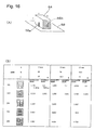
- Fig. 25 schematically shows a computer as a data processor processing microwave detection output data converted to a digital signal by an A-D converter and captured.
- 80 is a CPU
- 81 is a control part
- 82 is a data storage memory
- 83 is a display unit such as a CRT or a liquid crystal panel
- 84 is a printer
- 85 is an input unit such as a keyboard and others.
- a control program storage part 811 includes a microwave power supply program and others in addition to a program controlling operations of the overall device.
- a sample control program storage part 812 for example, stores a program controlling the operation of rotating the sample or the dielectric resonator in the embodiment of Fig. 14, or the operation of switching the operating rod antenna pairs in the embodiment of Fig. 24.
- a sampling program storage part 813 stores a sampling program for detection data, and the sampling program controls the timing of detection data sampling and the timing of A-D conversion by the A-D converter 138.
- a data processing program stored in a data processing program storage part 814 controls processing such as storage, arithmetic processing and others of measurement data (including data such as transmission or reflection microwave intensity detection data and a measured microwave frequency corresponding thereto, a use number, a rotational angle of a sample and the like) sampled and introduced into this data processor, and performs formation of an orientation pattern from the measurement data and operation induction of the orientation direction and the degree of orientation.
- measurement data including data such as transmission or reflection microwave intensity detection data and a measured microwave frequency corresponding thereto, a use number, a rotational angle of a sample and the like
- An output program stored in an output program storage part 815 controls an operation of selecting the orientation pattern, the orientation direction, the degree of orientation and the like at any time and outputting the same to the display unit 83 or the printer 84.
- the data storage memory 82 comprises an input buffer memory area 821 for temporarily storing the measurement data introduced into this data processor, a processing data area 822 storing processing data calculating the orientation direction, the degree of orientation, the orientation pattern and others from these data, a storage area 823 of basic data for data processing, an output buffer memory area 824 storing or updating displayed or printed data at any time and the like.
- a rotary encoder 53 is provided for detecting the rotational angle of a sample or a dielectric resonator.
- 52 is a frequency counter, which is provided on, for example, a microwave oscillator.
- a rotational angle signal of the sample by the rotary encoder 53 and a measured frequency signal by the frequency counter 52 are introduced into this data processor in correspondence to sample transmission or reflection microwave intensity detection data by the A-D converter.
Landscapes
- Physics & Mathematics (AREA)
- Electromagnetism (AREA)
- Health & Medical Sciences (AREA)
- Life Sciences & Earth Sciences (AREA)
- Chemical & Material Sciences (AREA)
- Analytical Chemistry (AREA)
- Biochemistry (AREA)
- General Health & Medical Sciences (AREA)
- General Physics & Mathematics (AREA)
- Immunology (AREA)
- Pathology (AREA)
- Measurement Of Resistance Or Impedance (AREA)
Claims (9)
- Instrument de mesure d'orientation, comprenant :un résonateur diélectrique (20 ; 54 ; 62) présentant un plan près de ou en contact avec un échantillon (48) et disposé uniquement sur un côté de la surface de l'échantillon (48) ;un excitateur de micro-ondes (26 ; 70) générant un vecteur de champ électrique ayant une composante unidirectionnelle à une fréquence à proximité de la fréquence de résonance dudit résonateur diélectrique (20 ; 54 ; 62) lorsque l'échantillon (48) est présent et dans un plan dans l'échantillon parallèle audit plan dans ledit résonateur diélectrique (20 ; 54 ; 62) ;un détecteur (28 ; 72) détectant l'énergie de transmission ou l'énergie de réflexion dudit résonateur diélectrique (20 ; 54 ; 62) ;un mécanisme de rotation (42, 44, 46) faisant tourner ledit échantillon (48) ou ledit résonateur diélectrique (20 ; 54 ; 62) dans un plan parallèle audit plan ; etun processeur de données (32) obtenant l'anisotropie diélectrique de l'échantillon (48) à partir de la variance d'une sortie de détection dudit détecteur (28 ; 72) après rotation par le mécanisme de rotation (42, 44, 46),dans lequel les bornes (56a, 56b) dudit excitateur (26 ; 70) et dudit détecteur (28 ; 72) sont des antennes tiges en forme de barre ayant été disposées dans une direction perpendiculaire au plan dudit résonateur diélectrique (20 ; 54 ; 62) près de ou en contact avec l'échantillon (48).
- Instrument de mesure d'orientation, comprenant :une pluralité de résonateurs diélectriques (20a, 20b, 20c) comprenant des plans près de ou en contact avec un échantillon (48) et disposés l'un près de l'autre uniquement du même côté de surface de l'échantillon (48) ;un excitateur de micro-ondes (26 ; 70) générant des vecteurs de champ électrique ayant des composantes unidirectionnelles, les vecteurs de champ électrique ayant des directions différentes l'une de l'autre à une fréquence à proximité de la fréquence de résonance desdits résonateurs diélectriques (20a, 20b, 20c) lorsque l'échantillon (48) est présent et dans un plan dans l'échantillon parallèle auxdits plans dans les résonateurs diélectriques respectifs (20a, 20b, 20c) ;des détecteurs (28 ; 72) pour les résonateurs diélectriques respectifs (20a, 20b, 20c) détectant l'énergie de transmission ou l'énergie de réflexion de ces résonateurs diélectriques (20a, 20b, 20c) ; etun processeur de données (32) obtenant l'anisotropie diélectrique de l'échantillon (48) à partir de la variance des sorties de détection desdits détecteurs (28 ; 72) auxdits vecteurs de champ électrique de directions différentes de ladite pluralité des résonateurs diélectriques (20a, 20b, 20c),dans lequel les bornes desdits excitateurs (26 ; 70) et desdits détecteurs (28 ; 72) sont des antennes tiges en forme de barre ayant été disposées dans une direction perpendiculaire aux plans desdits résonateurs diélectriques (20a, 20b, 20c) près de ou en contact avec l'échantillon (48).
- Instrument de mesure d'orientation, comprenant :un résonateur diélectrique (62) présentant un plan près de ou en contact avec un échantillon (48) et disposé uniquement d'un côté de surface de l'échantillon (48) ;une pluralité d'ensembles, les ensembles d'excitateurs de micro-ondes (70) générant des vecteurs de champ électrique ayant des composantes unidirectionnelles à une fréquence à proximité de la fréquence de résonance dudit résonateur diélectrique (62) lorsque l'échantillon (48) est présent et dans un plan dans l'échantillon parallèle audit plan dans ledit résonateur diélectrique (62) et les détecteurs (72) détectant l'énergie de transmission ou l'énergie de réflexion dudit résonateur diélectrique (62), disposés en des positions différentes l'une de l'autre par rapport audit résonateur diélectrique (62) ;une commande de commutation (65, 67, 68) sélectionnant un ensemble parmi ladite pluralité d'ensembles d'excitateurs de micro-ondes (70) et de détecteurs (72) et commandant ce dernier en séquence ; etun processeur de données (32) obtenant l'anisotropie diélectrique de l'échantillon (48) à partir de la variance des sorties de détection desdits détecteurs (72) après commutation par ladite commande de commutation (65, 67, 68),dans lequel les bornes (56a-1, 56a-2, 56a-3, 56b-1, 56b-2, 56b-3) dudit excitateur (70) et dudit détecteur (72) sont des antennes tiges en forme de barre ayant été disposées dans une direction perpendiculaire au plan dudit résonateur diélectrique (62) près de ou en contact avec l'échantillon (48).
- Instrument de mesure d'orientation selon l'une quelconque des revendications 1 à 3, utilisant la variance de la fréquence de résonance comme variance de ladite ou desdites sorties de détection.
- Instrument de mesure d'orientation selon la revendication 1, 2 ou 3, dans lequel ledit ou lesdits excitateurs (26 ; 70) et ledit ou lesdits détecteurs (28 ; 72) comprennent une paire de bornes disposées opposées dans le ou les résonateurs diélectriques (20 ; 20a. 20b, 20c ; 54 ; 62) pour détecter l'énergie de transmission dudit ou desdits détecteurs (28 ; 72).
- Instrument de mesure d'orientation selon la revendication 1, 2 ou 3, dans lequel ledit ou lesdits résonateurs diélectriques (20 ; 20a, 20b, 20c ; 62) est ou sont un résonateur cylindrique.
- Instrument de mesure d'orientation selon la revendication 1, 2 ou 3, dans lequel ledit ou lesdits résonateurs diélectriques (54) est ou sont un résonateur carré.
- Instrument de mesure d'orientation selon la revendication 1, 2 ou 3, dans lequel le pourtour dudit ou desdits résonateurs diélectriques (20 ; 20a, 20b, 20c ; 54 ; 62) est recouvert d'un matériau de protection (35, 64) consistant en un matériau conducteur, sauf une surface de mesure d'échantillon.
- Instrument de mesure d'orientation selon la revendication 10, dans lequel un autre matériau de protection (66) consistant en un matériau conducteur est également disposé du côté de la surface de mesure d'échantillon dudit ou desdits résonateurs diélectriques (20 ; 20a, 20b, 20c ; 54 ; 62), et l'échantillon (48) est disposé entre la surface de mesure d'échantillon du ou des résonateurs diélectriques (20 ; 20a, 20b, 20c ; 54 ; 62) et ledit matériau de protection du côté de la surface de mesure d'échantillon.
Applications Claiming Priority (5)
| Application Number | Priority Date | Filing Date | Title |
|---|---|---|---|
| JP9513597 | 1997-03-28 | ||
| JP9513597 | 1997-03-28 | ||
| JP26098497 | 1997-09-08 | ||
| JP26098497A JP3731314B2 (ja) | 1997-03-28 | 1997-09-08 | 配向測定装置 |
| PCT/JP1998/001356 WO1998044340A1 (fr) | 1997-03-28 | 1998-03-25 | Instrument de mesure d'orientations |
Publications (3)
| Publication Number | Publication Date |
|---|---|
| EP0973025A1 EP0973025A1 (fr) | 2000-01-19 |
| EP0973025A4 EP0973025A4 (fr) | 2003-02-12 |
| EP0973025B1 true EP0973025B1 (fr) | 2006-07-05 |
Family
ID=26436420
Family Applications (1)
| Application Number | Title | Priority Date | Filing Date |
|---|---|---|---|
| EP98911025A Expired - Lifetime EP0973025B1 (fr) | 1997-03-28 | 1998-03-25 | Instrument de mesure d'orientations |
Country Status (6)
| Country | Link |
|---|---|
| US (2) | USRE40488E1 (fr) |
| EP (1) | EP0973025B1 (fr) |
| JP (1) | JP3731314B2 (fr) |
| CA (1) | CA2284900C (fr) |
| DE (1) | DE69835146T2 (fr) |
| WO (1) | WO1998044340A1 (fr) |
Families Citing this family (9)
| Publication number | Priority date | Publication date | Assignee | Title |
|---|---|---|---|---|
| EP1116951A4 (fr) | 1998-09-25 | 2003-05-14 | Oji Paper Co | Procede et dispositif pour mesurer une constante dielectrique |
| US20020050828A1 (en) * | 2000-04-14 | 2002-05-02 | General Dielectric, Inc. | Multi-feed microwave reflective resonant sensors |
| DE10112499B4 (de) | 2001-03-15 | 2010-08-19 | Hauni Maschinenbau Ag | Resonatoreinrichtung, insbesondere Mikrowellenresonatoreinrichtung |
| US6989675B2 (en) * | 2003-03-13 | 2006-01-24 | Multimetrixs Llc | Method and apparatus for precision measurement of film thickness |
| JP4581820B2 (ja) * | 2005-04-28 | 2010-11-17 | 王子製紙株式会社 | 配向測定装置および配向測定方法 |
| JP2006349425A (ja) * | 2005-06-14 | 2006-12-28 | Oji Paper Co Ltd | 坪量測定方法及び装置 |
| JP4711988B2 (ja) * | 2007-03-15 | 2011-06-29 | 富士通株式会社 | 超伝導ディスク共振器、その作製方法、および誘電率異方性の評価方法 |
| US8410792B2 (en) * | 2009-03-02 | 2013-04-02 | Forschungszentrum Juelich Gmbh | Resonator arrangement and method for analyzing a sample using the resonator arrangement |
| JP6301739B2 (ja) * | 2014-06-02 | 2018-03-28 | 京セラ株式会社 | 誘電特性測定方法 |
Family Cites Families (35)
| Publication number | Priority date | Publication date | Assignee | Title |
|---|---|---|---|---|
| US4500385A (en) * | 1984-04-06 | 1985-02-19 | Waggoner Dennis H | Lumber assembly machine |
| JPS6176942A (ja) * | 1984-09-22 | 1986-04-19 | Kanzaki Paper Mfg Co Ltd | 誘電体シートの配向性又は誘電特性の測定方法 |
| JPS6183946A (ja) * | 1984-10-01 | 1986-04-28 | Kanzaki Paper Mfg Co Ltd | シ−ト状物質の配向測定方法 |
| JPS61204549A (ja) * | 1985-03-07 | 1986-09-10 | Kanzaki Paper Mfg Co Ltd | 試料の構成繊維の配向測定装置 |
| JPH0714870Y2 (ja) * | 1986-02-18 | 1995-04-10 | 新王子製紙株式会社 | シート状物の高周波特性測定装置 |
| US4841223A (en) * | 1987-06-17 | 1989-06-20 | The Institute Of Paper Chemistry | Method and apparatus for measuring fiber orientation anisotropy |
| EP0320442B1 (fr) * | 1987-11-27 | 1992-04-15 | Karl-Heinz Schmall | Application d'un résonateur diélectrique d'hyperfréquence et circuit de détection |
| JPH01163645A (ja) * | 1987-12-21 | 1989-06-27 | Kanzaki Paper Mfg Co Ltd | シート状材料の高周波特性測定装置 |
| JPH01270648A (ja) * | 1988-04-22 | 1989-10-27 | Kanzaki Paper Mfg Co Ltd | 材料の電気的特性測定装置 |
| JPH0229982A (ja) * | 1988-07-18 | 1990-01-31 | Taiyo Yuden Co Ltd | 磁気テープ脱落防止法および防止用カバー |
| US4904928A (en) | 1988-12-09 | 1990-02-27 | E. I. Du Pont De Nemours And Company | Measurement apparatus and method utilizing multiple resonant modes of microwave energy |
| JPH0339632A (ja) * | 1989-07-06 | 1991-02-20 | Hitachi Ltd | シヤシダイナモメータの制御装置 |
| US5119034A (en) * | 1989-07-12 | 1992-06-02 | Murata Manufacturing Co., Ltd. | Method of measuring dielectric material constants and measuring device employed therefor |
| JP2501910B2 (ja) * | 1989-08-10 | 1996-05-29 | シャープ株式会社 | ファクシミリ信号伝送方式 |
| JPH0370368U (fr) * | 1989-11-08 | 1991-07-15 | ||
| JP2796752B2 (ja) * | 1990-04-27 | 1998-09-10 | 日本軽金属株式会社 | 耐食皮膜用Al―Ni―Si合金製スパッタリングターゲット |
| FR2685490B1 (fr) * | 1991-12-19 | 1996-05-15 | Commissariat Energie Atomique | Dispositif de mesure de parametres dielectriques et magnetiques de materiaux et systeme de mesure desdits parametres utilisant ce dispositif. |
| DE4204369C2 (de) * | 1992-02-14 | 1994-08-25 | Forschungszentrum Juelich Gmbh | Verfahren zur Qualitätsbestimmung eines einzelnen supraleitenden Filmes und Vorrichtung zur Durchführung dieses Verfahrens |
| DK0656123T3 (da) * | 1992-08-21 | 1996-11-18 | Du Pont | Apparatur til karakteristikbestemmelse af højtemperatur-supraledende tyndfilm |
| US5334941A (en) * | 1992-09-14 | 1994-08-02 | Kdc Technology Corp. | Microwave reflection resonator sensors |
| JPH0714870A (ja) * | 1993-06-23 | 1995-01-17 | Fujitsu Miyagi Electron:Kk | 半導体装置の製造方法とその製造装置 |
| US5532604A (en) * | 1993-08-31 | 1996-07-02 | New Oji Paper Co. Ltd. | Dielectric constant measuring method and apparatus |
| JPH07120515A (ja) | 1993-08-31 | 1995-05-12 | New Oji Paper Co Ltd | 誘電率測定装置 |
| JPH07103917A (ja) * | 1993-09-30 | 1995-04-21 | New Oji Paper Co Ltd | 材料の異方性測定方法 |
| DE4342505C1 (de) * | 1993-12-08 | 1995-04-27 | Stange Gerd | Verfahren und Vorrichtung zur Messung der Dielektrizitätskonstante von Probenmaterialien |
| JPH07270342A (ja) * | 1994-02-08 | 1995-10-20 | New Oji Paper Co Ltd | 分子配向測定方法及び装置 |
| JP2704704B2 (ja) * | 1994-04-06 | 1998-01-26 | 日本製紙株式会社 | 紙の表面の繊維配向性測定方法 |
| GB2294326A (en) | 1994-10-06 | 1996-04-24 | Scapa Group Plc | Moisture detection meter |
| JPH08122375A (ja) * | 1994-10-26 | 1996-05-17 | Mitsubishi Heavy Ind Ltd | 液体の誘電特性測定装置 |
| US5898586A (en) | 1994-11-04 | 1999-04-27 | Eli Lilly And Company | Method for administering clinical trail material |
| JPH08271449A (ja) * | 1995-03-29 | 1996-10-18 | New Oji Paper Co Ltd | 分子配向測定装置および分子配向測定法 |
| FI953114A0 (fi) * | 1995-06-21 | 1995-06-21 | Valtion Teknillinen | Maetningsfoerfarande baserat pao RF- eller mikrovaogsresornatorer foer bestaemning av fiberorienteringen hos papper och kartong |
| EP1116951A4 (fr) * | 1998-09-25 | 2003-05-14 | Oji Paper Co | Procede et dispositif pour mesurer une constante dielectrique |
| US6375875B1 (en) * | 2000-01-27 | 2002-04-23 | Ut-Battelle, Llc | Diagnostic monitor for carbon fiber processing |
| US6538454B1 (en) * | 2000-09-08 | 2003-03-25 | Yissum Research Development Company Of The Hebrew University Jerusalem | Near field microwave resistivity microscope including a dielectric resonator |
-
1997
- 1997-09-08 JP JP26098497A patent/JP3731314B2/ja not_active Expired - Fee Related
-
1998
- 1998-03-25 WO PCT/JP1998/001356 patent/WO1998044340A1/fr not_active Ceased
- 1998-03-25 US US10/740,393 patent/USRE40488E1/en not_active Expired - Lifetime
- 1998-03-25 DE DE69835146T patent/DE69835146T2/de not_active Expired - Lifetime
- 1998-03-25 CA CA002284900A patent/CA2284900C/fr not_active Expired - Fee Related
- 1998-03-25 US US09/380,583 patent/US6396288B1/en not_active Ceased
- 1998-03-25 EP EP98911025A patent/EP0973025B1/fr not_active Expired - Lifetime
Also Published As
| Publication number | Publication date |
|---|---|
| WO1998044340A1 (fr) | 1998-10-08 |
| CA2284900C (fr) | 2006-10-03 |
| EP0973025A1 (fr) | 2000-01-19 |
| JP3731314B2 (ja) | 2006-01-05 |
| USRE40488E1 (en) | 2008-09-09 |
| US6396288B1 (en) | 2002-05-28 |
| DE69835146T2 (de) | 2007-06-14 |
| JPH10325811A (ja) | 1998-12-08 |
| DE69835146D1 (de) | 2006-08-17 |
| EP0973025A4 (fr) | 2003-02-12 |
| CA2284900A1 (fr) | 1998-10-08 |
Similar Documents
| Publication | Publication Date | Title |
|---|---|---|
| US6496018B1 (en) | Method and device for measuring dielectric constant | |
| Hajnal | Observations of singularities in the electric and magnetic fields of freely propagating microwaves | |
| EP0973025B1 (fr) | Instrument de mesure d'orientations | |
| WO2006063205A2 (fr) | Criblage a rendement eleve de catalyseurs au moyen d'une resonance magnetique | |
| JP2006275614A (ja) | 空洞共振器を用いて複素誘電率を測定する装置 | |
| EP0177011B1 (fr) | Procédé pour mesurer l'orientation de matériaux sous forme de feuille ou de tissu | |
| US6049211A (en) | Method and apparatus for determination of fiber orientation in paper or paperboard web | |
| JP3772603B2 (ja) | 配向測定装置 | |
| US5532604A (en) | Dielectric constant measuring method and apparatus | |
| JP4000789B2 (ja) | 配向測定装置 | |
| Osaki | A new microwave cavity resonator for determining molecular orientation and dielectric anisotropy of sheet materials | |
| Borovik-Romanov et al. | NMR in 55Mn2+ nuclei in the quasi-one-dimensional antiferromagnetic CsMnBr3 | |
| JP2007248097A (ja) | 誘電率異方性測定方法及び装置 | |
| JP3691659B2 (ja) | マイクロ波共振系の固有振動数演算方法および装置 | |
| JPH11287771A (ja) | マイクロ波を用いた分子配向度計測方法および装置 | |
| JP2009042007A (ja) | 配向測定装置及び配向測定方法 | |
| JP5029421B2 (ja) | 配向測定装置 | |
| JPH0618287Y2 (ja) | 材料の異方性測定装置 | |
| JPH07270342A (ja) | 分子配向測定方法及び装置 | |
| RU2094783C1 (ru) | Способ определения поверхностного сопротивления высокопроводящих материалов | |
| SU1589220A1 (ru) | Способ контрол параметров диэлектриков, имеющих цилиндрическую форму | |
| Zhao et al. | Tensor permittivity measurements of thin films at millimeter wavelengths | |
| Shigeru Nakayama | Development of microwave caliper for sheet materials | |
| AU2024244686A1 (en) | Apparatus and method for generating or supporting an electromagnetic wave with non -zero helicity | |
| Borovik-Romanov et al. | NMR in [sup 55] Mn [sup 2+] nuclei in the quasi-one-dimensional antiferromagnetic CsMnBr [sub 3]. |
Legal Events
| Date | Code | Title | Description |
|---|---|---|---|
| PUAI | Public reference made under article 153(3) epc to a published international application that has entered the european phase |
Free format text: ORIGINAL CODE: 0009012 |
|
| 17P | Request for examination filed |
Effective date: 19990910 |
|
| AK | Designated contracting states |
Kind code of ref document: A1 Designated state(s): DE FI FR GB SE |
|
| A4 | Supplementary search report drawn up and despatched |
Effective date: 20030102 |
|
| RIC1 | Information provided on ipc code assigned before grant |
Ipc: 7G 01R 27/26 B Ipc: 7G 01N 22/00 A |
|
| 17Q | First examination report despatched |
Effective date: 20050630 |
|
| GRAP | Despatch of communication of intention to grant a patent |
Free format text: ORIGINAL CODE: EPIDOSNIGR1 |
|
| GRAS | Grant fee paid |
Free format text: ORIGINAL CODE: EPIDOSNIGR3 |
|
| GRAA | (expected) grant |
Free format text: ORIGINAL CODE: 0009210 |
|
| AK | Designated contracting states |
Kind code of ref document: B1 Designated state(s): DE FI FR GB SE |
|
| REG | Reference to a national code |
Ref country code: GB Ref legal event code: FG4D |
|
| REF | Corresponds to: |
Ref document number: 69835146 Country of ref document: DE Date of ref document: 20060817 Kind code of ref document: P |
|
| REG | Reference to a national code |
Ref country code: SE Ref legal event code: TRGR |
|
| ET | Fr: translation filed | ||
| PLBE | No opposition filed within time limit |
Free format text: ORIGINAL CODE: 0009261 |
|
| STAA | Information on the status of an ep patent application or granted ep patent |
Free format text: STATUS: NO OPPOSITION FILED WITHIN TIME LIMIT |
|
| 26N | No opposition filed |
Effective date: 20070410 |
|
| REG | Reference to a national code |
Ref country code: FR Ref legal event code: PLFP Year of fee payment: 18 |
|
| PGFP | Annual fee paid to national office [announced via postgrant information from national office to epo] |
Ref country code: FI Payment date: 20150311 Year of fee payment: 18 Ref country code: DE Payment date: 20150320 Year of fee payment: 18 |
|
| PGFP | Annual fee paid to national office [announced via postgrant information from national office to epo] |
Ref country code: SE Payment date: 20150319 Year of fee payment: 18 Ref country code: FR Payment date: 20150319 Year of fee payment: 18 Ref country code: GB Payment date: 20150319 Year of fee payment: 18 |
|
| REG | Reference to a national code |
Ref country code: DE Ref legal event code: R119 Ref document number: 69835146 Country of ref document: DE |
|
| PG25 | Lapsed in a contracting state [announced via postgrant information from national office to epo] |
Ref country code: FI Free format text: LAPSE BECAUSE OF NON-PAYMENT OF DUE FEES Effective date: 20160325 |
|
| REG | Reference to a national code |
Ref country code: SE Ref legal event code: EUG |
|
| GBPC | Gb: european patent ceased through non-payment of renewal fee |
Effective date: 20160325 |
|
| PG25 | Lapsed in a contracting state [announced via postgrant information from national office to epo] |
Ref country code: SE Free format text: LAPSE BECAUSE OF NON-PAYMENT OF DUE FEES Effective date: 20160326 |
|
| REG | Reference to a national code |
Ref country code: FR Ref legal event code: ST Effective date: 20161130 |
|
| PG25 | Lapsed in a contracting state [announced via postgrant information from national office to epo] |
Ref country code: GB Free format text: LAPSE BECAUSE OF NON-PAYMENT OF DUE FEES Effective date: 20160325 Ref country code: DE Free format text: LAPSE BECAUSE OF NON-PAYMENT OF DUE FEES Effective date: 20161001 Ref country code: FR Free format text: LAPSE BECAUSE OF NON-PAYMENT OF DUE FEES Effective date: 20160331 |