EP0982144A1 - Système d'entraínement recto-verso du support d'impression - Google Patents
Système d'entraínement recto-verso du support d'impression Download PDFInfo
- Publication number
- EP0982144A1 EP0982144A1 EP99306507A EP99306507A EP0982144A1 EP 0982144 A1 EP0982144 A1 EP 0982144A1 EP 99306507 A EP99306507 A EP 99306507A EP 99306507 A EP99306507 A EP 99306507A EP 0982144 A1 EP0982144 A1 EP 0982144A1
- Authority
- EP
- European Patent Office
- Prior art keywords
- media
- media sheet
- path
- sheet
- printer
- Prior art date
- Legal status (The legal status is an assumption and is not a legal conclusion. Google has not performed a legal analysis and makes no representation as to the accuracy of the status listed.)
- Granted
Links
- 238000007639 printing Methods 0.000 title claims abstract description 48
- 230000002441 reversible effect Effects 0.000 claims abstract description 11
- 238000010438 heat treatment Methods 0.000 claims abstract description 6
- 238000003384 imaging method Methods 0.000 claims description 36
- 238000012546 transfer Methods 0.000 claims description 29
- 238000000034 method Methods 0.000 claims description 22
- 230000008859 change Effects 0.000 claims description 13
- 239000007788 liquid Substances 0.000 claims description 10
- 239000000758 substrate Substances 0.000 claims description 3
- 239000012071 phase Substances 0.000 claims 7
- 238000007645 offset printing Methods 0.000 claims 2
- 230000000694 effects Effects 0.000 claims 1
- 239000000155 melt Substances 0.000 claims 1
- 239000007790 solid phase Substances 0.000 claims 1
- 239000007787 solid Substances 0.000 description 7
- 230000008901 benefit Effects 0.000 description 6
- PXHVJJICTQNCMI-UHFFFAOYSA-N Nickel Chemical compound [Ni] PXHVJJICTQNCMI-UHFFFAOYSA-N 0.000 description 4
- 230000008569 process Effects 0.000 description 4
- 238000013459 approach Methods 0.000 description 2
- 238000012423 maintenance Methods 0.000 description 2
- 238000012986 modification Methods 0.000 description 2
- 230000004048 modification Effects 0.000 description 2
- 229910052759 nickel Inorganic materials 0.000 description 2
- 230000000717 retained effect Effects 0.000 description 2
- 229910000831 Steel Inorganic materials 0.000 description 1
- XAGFODPZIPBFFR-UHFFFAOYSA-N aluminium Chemical compound [Al] XAGFODPZIPBFFR-UHFFFAOYSA-N 0.000 description 1
- 229910052782 aluminium Inorganic materials 0.000 description 1
- 230000004888 barrier function Effects 0.000 description 1
- 238000013461 design Methods 0.000 description 1
- 238000011161 development Methods 0.000 description 1
- 230000009977 dual effect Effects 0.000 description 1
- 238000005516 engineering process Methods 0.000 description 1
- 239000000463 material Substances 0.000 description 1
- 230000007246 mechanism Effects 0.000 description 1
- 238000002844 melting Methods 0.000 description 1
- 230000008018 melting Effects 0.000 description 1
- 238000012544 monitoring process Methods 0.000 description 1
- 230000037361 pathway Effects 0.000 description 1
- 230000002250 progressing effect Effects 0.000 description 1
- 239000010959 steel Substances 0.000 description 1
Images



Classifications
-
- B—PERFORMING OPERATIONS; TRANSPORTING
- B41—PRINTING; LINING MACHINES; TYPEWRITERS; STAMPS
- B41J—TYPEWRITERS; SELECTIVE PRINTING MECHANISMS, i.e. MECHANISMS PRINTING OTHERWISE THAN FROM A FORME; CORRECTION OF TYPOGRAPHICAL ERRORS
- B41J3/00—Typewriters or selective printing or marking mechanisms characterised by the purpose for which they are constructed
- B41J3/60—Typewriters or selective printing or marking mechanisms characterised by the purpose for which they are constructed for printing on both faces of the printing material
-
- B—PERFORMING OPERATIONS; TRANSPORTING
- B41—PRINTING; LINING MACHINES; TYPEWRITERS; STAMPS
- B41J—TYPEWRITERS; SELECTIVE PRINTING MECHANISMS, i.e. MECHANISMS PRINTING OTHERWISE THAN FROM A FORME; CORRECTION OF TYPOGRAPHICAL ERRORS
- B41J13/00—Devices or arrangements of selective printing mechanisms, e.g. ink-jet printers or thermal printers, specially adapted for supporting or handling copy material in short lengths, e.g. sheets
- B41J13/0009—Devices or arrangements of selective printing mechanisms, e.g. ink-jet printers or thermal printers, specially adapted for supporting or handling copy material in short lengths, e.g. sheets control of the transport of the copy material
- B41J13/0045—Devices or arrangements of selective printing mechanisms, e.g. ink-jet printers or thermal printers, specially adapted for supporting or handling copy material in short lengths, e.g. sheets control of the transport of the copy material concerning sheet refeed sections of automatic paper handling systems, e.g. intermediate stackers
-
- B—PERFORMING OPERATIONS; TRANSPORTING
- B41—PRINTING; LINING MACHINES; TYPEWRITERS; STAMPS
- B41J—TYPEWRITERS; SELECTIVE PRINTING MECHANISMS, i.e. MECHANISMS PRINTING OTHERWISE THAN FROM A FORME; CORRECTION OF TYPOGRAPHICAL ERRORS
- B41J29/00—Details of, or accessories for, typewriters or selective printing mechanisms not otherwise provided for
- B41J29/02—Framework
Definitions
- This invention relates generally to methods and apparatus for printing on two sides of a media sheet, and more particularly, to a media handling system which first feeds a media sheet with a first side exposed to a print source, then feeds the media sheet with a second side exposed to the print source.
- duplex printing Printing to two sides of a media sheet, referred to as duplex printing, is a desirable feature in printing systems, especially in desktop or office color printers as printing speeds increase.
- the advantages of duplex printing include reducing the amount of paper required compared to one-sided (simplex) printing, and generating print sets with layouts resembling that of professionally printed books.
- Conventional duplex printing devices employ complex paper handling mechanisms. Typically, an extra tray is used for temporary storage of pages having printing on a first side.
- a second paper path is provided to route a first printed page around the existing paper supply.
- Another approach utilizes a media re-feed guide that positively blocks the movement of media along a first path of travel and directs the media travel along a second path.
- duplex copying typically is accomplished by either one of two methods.
- first side copies are stacked in a duplex tray.
- the copies are fed out of the duplex tray and returned with an odd number of inversions along a duplex path to receive second side imaging.
- first side copies are returned directly to receive second side imaging without stacking.
- Solid ink printing employs a wax-like ink base that is jetted at a molten temperature and then solidifies as it cools on intermediate and final receiving substrates.
- Printing on the second side of a media sheet without melting or destroying the hardened image on the first side has been a barrier to duplex printing. Paper curling has also been a problem.
- the simple duplex printing apparatus and method are usable with solid or phase change ink.
- a passive media path diverter is utilized to change the media path from a simplex to a duplex path to achieve duplex printing when desired.
- the angle of the axis of the exit rollers from the vertical combines with the media stiffness and entrance angle of the duplex path to snap the trail end of the media above the passive media path diverter onto the duplex media path prior to reversing the direction of travel of the media to initiate duplex printing.
- the single image side of the media partially exits the printer into the output tray and then is reversed and drawn back into the duplex media path for imaging on the second side to complete the duplex printing.
- the reversed media path utilized to accomplish the duplex printing automatically presents the reverse or second side of the media for imaging without necessitating an active media flipping step or apparatus.
- sensors track the travel of the media about the media paths during the media travel from simplex to duplex printing.
- duplex printing method and apparatus does not melt or offset or otherwise degrade the solid ink first side image while accomplishing the second side imaging in an offset or indirect printing system.
- duplex printing system utilized in an offset solid ink desktop printer to accomplish rapid, low cost, and high quality duplex printing.
- Fig. 1 shows the desktop printer indicated generally by the numeral 10 which has a media output area 11 for receiving and holding a plurality of completed image output.
- An operator front panel permitting the operator to select certain operating features and to obtain feedback information as indicated generally by the numeral 12 mounted on an ink loader access cover 14 which permits replenishment of solid ink sticks while the printer is operating.
- a media path access cover 15 is hingedly affixed to the front of the printer 10 to permit access to the paper path and viewing of the media handling apparatus while a hand feed access door 17 is lowerable from cover 15 to permit hand feeding of selected media.
- a removable media tray 16 is positioned beneath the access cover 15 to provide the desired media for imaging the use of the printer. Side 18 of the printer is shown having air vents to permit air circulation to flow through the printer.
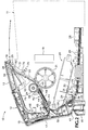
- Fig. 2 there are shown in an enlarged partial side sectional view the operative parts of the printer 10 which are employed in transporting and imaging a media sheet as it passes through the printer.
- Diagrammatically illustrated is the media output area 11 and print head 19.
- Print head 19 applies molten phase change colored ink to a liquid intermediate transfer surface that is applied by an appropriate contact surface, such as a wick or web (not shown) contained within the drum maintenance unit, indicated generally by the numeral 20, to the arcuate support surface of a rotatable support drum 21.
- an appropriate contact surface such as a wick or web (not shown) contained within the drum maintenance unit, indicated generally by the numeral 20
- the image present on the liquid intermediate transfer layer on drum 21 is contact transferred to the media sheet 29 and then fused by the combination of heat and pressure applied between drum 21 and transfer and fusing roller 24 to complete the offset or indirect imaging process prior to the imaged media sheet 29 passing through the exit rollers 25 and 26, only one of each of which are shown, into the media output area 11.
- the indirect printing process employed in the printer utilizing the present invention is described in greater detail in U.S. Patent No. 5,389,958 entitled “Imaging Process", issued February 14, 1995; the print head 19 utilized in the printer employing the present invention is representative of that described in greater detail in U.S. Patent No.
- Fig. 2 shows individual sheets of print media 29 contained in the media supply tray receptacle 28 and a print media pick function that employs a pick roller 30 which picks a single sheet 29 of print medium from the media supply tray receptacle 28 by a single rotation of the shaft 31 which can be driven by any appropriate means, such as a flapper solenoid (not shown).
- the print media sheet 29 is drawn along a first simplex paper path, indicated by the arrow 32, by lower transport rollers 34, only one of which is shown in Fig. 2.
- Fig. 2 also shows a media auxiliary tray feed chute 35 that delivers sheets of media from an auxiliary tray (not shown) which optionally can be utilized beneath printer 10.
- Feed chute 35 delivers the print media into the simplex media path 32 via appropriate paper pick and transport means and into contact with the lower transport rollers 34.
- a media guide and idler roller support 36 is shown cooperative with the one illustrated lower transport roller 34 to help guide media along path 32.
- Media sheets 29 coming out of media supply tray receptacle 28 also are guided along their path by the media guide surface 38 located intermediate the pick roller 30 and the lower transport roller 34.
- media sheets 29 are driven and guided through the simplex media path 32, they pass through a simplex buckle deskew area 39 that permits the individual media sheets 29 to align themselves correctly prior to passing into the nip, indicated generally by the numeral 37, formed by the upper transport rollers 40.
- a series of flexible guide fingers are employed in the simplex buckle deskew area 39, which is located in the hingedly mounted media path access cover 15 that pivots about door pin 41.
- Media sheets 29 continue progressing from the simplex media path 32 to the media path 33 common to both simplex and duplex printing through the upper transport rollers 40 into the media preheater assembly indicated generally by the numeral 42.
- Preheater assembly 42 includes a media preheater plate 44 that is made from electroless nickel plated aluminum and which is connected via an electrical connecting cable 45 to a circuit board 46 that controls the resistance heating elements used to heat the preheater plate 44 to the desired temperature.
- the media preheater assembly 42 also includes a preheater sensor body and bracket 46, partially shown.
- a preheater assembly media guide plate 48 underlies the media path and the heater plate 44 to support media sheets 29 passing thereover into the transfer and fixing nip 49 formed between the support drum 21 and the transfer and fusing roller 24, at which location the contact transfer to the media sheet 29 of the image applied by print head 19 to the liquid intermediate transfer layer on the surface of support drum 21 is accomplished.
- a stripper finger contact assembly 50 strips the media sheet 29 from the surface of drum 21 and continues to guide it upwardly onto the hinged media guide 51 with a plurality of guide ribs 62 (only one of which is shown) which underlie the media outer strip guide surfaces 52 (again only one of which is shown).
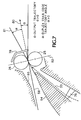
- the media sheet 29 continues passing upwardly beneath the stationary or passive media path diverter 54 into the exit rollers 25 and 26 whose axes, when connected by a straight line 82 as seen in Fig. 7, are offset from the vertical to facilitate both directing the trailing edge 27 of media sheet 29 back into the printer 10 above the tip 55 of passive media path diverter 54 and proper stacking of printed media sheets 29 in the output area 11.
- the tangent line 80 for the duplex media path 58 is above the tangent line 81 of the top surface of the passive media path diverter 54.
- the media sheet 29 passes out between the exit rollers 25 and 26 in simplex printing all the way into the media output area 11.
- the printer controller (not shown) signals the printer to reverse the driven roller 25 when the media sheet 29 has progressed sufficiently passed the tip 55 of the passive media path diverter 54, as shown between Figs. 4 and 5.
- Fig. 4 shows the media sheet 29 as it is just about to complete its forward progress into the output area 11 with the trailing edge 27 of media sheet 29 still retained just at the tip 55 of the passive media path diverter 54.
- FIG. 5 shows the trailing edge 27 having been advanced forwardly of the tip 55 of the passive media path diverter 54, so that the combination of the stiffness of the media and the positioning of the exit rollers 25 and 26 have combined to snap or raise the trailing edge 27 of the media sheet 29 above and beyond the passive media path diverter 54.
- the printer controller (not shown) reverses the direction of rotation of the driven exit roller 25 to draw the media sheet 29 back into the printer and into the duplex media path indicated by the arrow 58, best seen in Fig. 6.
- the media sheet 29 is partially exited from the printer 10 into a media output area 11 and then is drawn back into the printer along the duplex path of travel 58 that automatically reverses the media sheet 29 so that the trailing edge 27 of the media sheet 29 becomes the leading edge during the imaging of the second side of the media sheet 29.
- Media sheet 29 is conveyed along duplex media path 58 by the exit rollers 25 and 26 which are biased by springs (not shown) retained in place on roller biasing supports 59 (only one of which is shown) within the assembly that includes upper media path access cover 13.
- the upper portion 53 of guide surface 52 and the duplex upper media guide 60 define the pathway between which media sheet 29 is passed along the duplex media path 58.
- Upper media guide 60 also has guide ribs 61 (only one of which is shown) and is a molded portion of the pivotable assembly that includes access cover 14.
- Plastic cover supports 62 supply support for the upper media guides 60 in the plastic molded cover 14.
- the cover assembly with display 12 has plastic molded supporting structure 64 which acts as a media guide along the upper surface of duplex media path 58.
- a nickel plated steel plate 65 serves as a guide for the bottom portion of the duplex media path 58 beneath the cover assembly in which display 12 is found.
- plastic molded guides 68 in access cover 15 direct the media sheet 29 into the duplex buckle deskew area 69.
- media sheet 29 is buckled within the buckle deskew area 69 to permit the individual media sheets 29 to become properly aligned and then proceed through upper transport rollers 40 along the common media path 33 through the media preheater assembly 42 and through the transfer and fusing nip 49 previously described.
- the media sheet 29 receives the image applied from the print head 19 to the liquid intermediate transfer layer on the surface of support drum 21 and then is conveyed upwardly beneath the stationary or passive media path diverter 54 and out through the exit rollers 25 and 26 where the duplex imaged media sheet 29 is deposited in the media output area 11, best seen in Fig. 2.
- a series of sensors track the progress of media sheets 29 about the media paths 32, 33 and 58, depending upon the selected printing mode. All of the sensors provide feedback into the printer controller (not shown) to track the status of the media sheet 29 within the printer 10.
- Sensors employed at various locations throughout the paper paths 32, 33 and 58 are typically OJ series opto sensors available from Aleph International of San Fernando, California, which utilize a pivotable sensing flag within a sensing field established by the sensor. The initial flag encountered is the tray empty flag 70 seen in Fig. 2 that will indicate when the supply of media sheets 29 needs to be replenished.
- a pair of sensors adjacent the nip formed by the upper transport rollers 40 signal the arrival of the media at the nip and the size of the media sheet by the movement of left edge flag 71 and A-size media sheet detector flag 72, respectively.
- the opto sensor 75 with its stripper flag 76 indicates that the media sheet 29 has been successfully stripped from the transport and fusing roller 24 and continues along its path toward the exit rollers 25 and 26.
- the media sheet 29 passes through the nip between exit rollers 25 and 26, it hits the exit flag and full output tray sensor 78 which provides the dual purpose of monitoring the progress of the media sheet 29 through the exit rollers, as well as alerting the printer operator that the output area 11 is full of imaged media sheets and needs to be emptied, as appropriate.
- the media sheet 29 recommences its travel along duplex media path 58 and reenters the printer engaging duplex flag 79 in the display cover 13, best seen in Figs. 2 and 3 in the lowered position, to indicate successful reentry of the media sheet 29 into the printer and progress along the duplex media path 58.
- a media sheet 29 in the solid ink printer 10 Key to being able to duplex image a media sheet 29 in the solid ink printer 10 is the control of the temperature of the media sheet 29 and the various heating apparatus after the simplex imaging has occurred with the placement of molten ink on the liquid intermediate transfer layer on the surface of support drum 21 and its contact transfer in a malleable state to the media sheet 29 in the transfer and fusing nip 49.
- the transferred image continues to cool and harden into a ductile state on the one side of the image media sheet 29 and then media sheet 29 is recommenced along its duplex media path 58 by the reversing of the upper transport rollers 25 and 26.
- the temperature of the media preheater and the transfer and fusing drum 24 must be controlled so that the temperature is not elevated sufficiently high to remelt the hardened image on the first side of the media sheet 29.
- Prior phase change ink printers operated the preheat apparatus 42 and the transfer and fusing roller 24 such that the temperature was approximately 90° C in this area.
- the preheat and fusing temperatures are kept below 70° C, preferably between about 55° and 65° C, and most preferably at about 60° C.
- This temperature range provides sufficient heat to elevate the temperature of the image receiving medium, transfer and fuse the malleable image from the liquid intermediate transfer layer on the surface of support drum 21 onto the media sheet 29 to have successful imaging both in simplex and duplex printing and still avoid remelting or smudging the first side or simplex imaged media sheet 29 during the duplex imaging step.
- the imaged first side of the media sheet is not affected during the duplex imaging step.
- the printer 10 has the pick roller 30 pick a media sheet 29 from the media supply tray receptacle 28 in the removable media tray 16 and start along the media path 32 by directing the sheet 29 into the lower transport rollers 34.
- Transport rollers 34 continue guiding the sheet forward along simplex media path 32 into the simplex buckle deskew area 39 where the media sheet 29, in cooperation with media guide fingers (not shown), is aligned prior to entry into the nip form by the upper transport rollers 40.
- the fingers both guide and provide a spring force unaffected by humidity that presses the lead edge into the stalled rollers, thus aligning the single media sheet prior to printing.
- a left edge detector flag 71 and A-size media detector flag 72 sense the media sheet 29 as it enters the transport rollers 40.
- the media preheater assembly 42 utilizes resistance heaters controlled by a circuit board 43 to heat the media between the preheater guide plate 48 and the heater plate 44 to the appropriate temperature so that the media sheet upon passing therethrough achieves a temperature which is approximately 60° C. Passing out of the media preheater assembly 42, the media sheet 29 actuates the preheater exit flag 74 to signal that the media sheet 29 is about to enter the transfer and fusing nip 49 where image transfer takes place from the liquid intermediate transfer layer on the surface of support drum 21 where the print head 19 has ejected the molten image that is now in a malleable state.
- the simplex image media sheet 29 is stripped from the support drum 21 by the stripper finger contact assembly 50 and continues along the common media path 33 where stripper flag 76 detects successful exiting from the nip 49.
- the media sheet 29 continues to travel up to the upper transport rollers 25 and 26 where the sensor activated by exit flag 78 signals the printer controller that the media sheet 29 is exiting the exit rollers 25 and 26 into the media output area 11.
- the media sheet 29 is deposited into the media output area 11 along the path indicated generally by the arrows in Fig. 2.
- duplex imaging is the technique that has been selected, the exit rollers 25 and 26 are stopped and the driven exit roller 25 is reversed to draw the simplex imaged media sheet 29 back into the printer along the duplex media path 58.
- the trailing edge 27 ofthe media sheet, prior to being drawn back into the printer 10, has passed beyond the tip 55 of passive media diverter 54 and, in combination with the stiffness of the media sheet and the positioning of the upper transport rollers 25 and 26, is snapped up above and beyond the tip 55 so that upon reversal of motion, the media sheet 29 follows the duplex media path 58.
- Upper transport rollers 25 and 26 direct the simplex imaged media sheet 29 along the duplex media path 58 between the duplex upper media guides 60, the supporting structure 64, and the plate 65 as it moves toward the duplex transport rollers 66.
- the duplex path sensor is signaled by movement of flag 79 to control movement of the media sheet 29 through the final stages of its movement back into the common media path 33.
- the duplex transport rollers 66 deliver the media sheet 29 into the duplex buckle deskew area which, similarly to the simplex buckle deskew area 39, aligns the media sheet 29 with the aid of the flexible guide fingers (not shown) prior to entry into the upper transport rollers 40.
- the left edge detector flag 71 and the A-size media detector flag 72 are activated as the media sheet passes through the upper transport rollers into the preheater assembly 42 where the simplex imaged media sheet 29 is heated to the temperature of approximately 60° so as to preheat the media, but not remelt or cause smudging of the simplex image.
- the exit from the media preheater 42 is continued as described earlier along the common media path 33 and the imaging of the second side of the media sheet 29 in the duplex imaging process is accomplished in like manner as previously described.
- the then duplex imaged media sheet 29 is transported upwardly along common media path 33 into the exit rollers 25 and 26 and the duplex imaged sheet 29 is ejected from the printer 10 into the media output area 11.
Landscapes
- Separation, Sorting, Adjustment, Or Bending Of Sheets To Be Conveyed (AREA)
- Handling Of Cut Paper (AREA)
- Conveyance By Endless Belt Conveyors (AREA)
Applications Claiming Priority (2)
| Application Number | Priority Date | Filing Date | Title |
|---|---|---|---|
| US09/141,927 US5974298A (en) | 1998-08-28 | 1998-08-28 | Duplex printing media handling system |
| US141927 | 1998-08-28 |
Publications (2)
| Publication Number | Publication Date |
|---|---|
| EP0982144A1 true EP0982144A1 (fr) | 2000-03-01 |
| EP0982144B1 EP0982144B1 (fr) | 2002-06-26 |
Family
ID=22497842
Family Applications (1)
| Application Number | Title | Priority Date | Filing Date |
|---|---|---|---|
| EP99306507A Expired - Lifetime EP0982144B1 (fr) | 1998-08-28 | 1999-08-18 | Système d'entraínement recto-verso du support d'impression |
Country Status (4)
| Country | Link |
|---|---|
| US (1) | US5974298A (fr) |
| EP (1) | EP0982144B1 (fr) |
| JP (1) | JP3749046B2 (fr) |
| DE (1) | DE69901923T2 (fr) |
Cited By (1)
| Publication number | Priority date | Publication date | Assignee | Title |
|---|---|---|---|---|
| KR20030083107A (ko) * | 2002-04-19 | 2003-10-30 | 삼성전자주식회사 | 양면 인쇄기기의 용지 이송 가이드장치 |
Families Citing this family (24)
| Publication number | Priority date | Publication date | Assignee | Title |
|---|---|---|---|---|
| JP2000344411A (ja) * | 1999-05-31 | 2000-12-12 | Hitachi Ltd | 両面印字装置 |
| US6374066B1 (en) * | 1999-06-29 | 2002-04-16 | Xerox Corporation | Arcuate surface apparatus design method |
| JP3962539B2 (ja) * | 1999-10-29 | 2007-08-22 | キヤノン株式会社 | 画像形成装置 |
| US6957886B2 (en) * | 2002-09-27 | 2005-10-25 | Eastman Kodak Company | Apparatus and method of inkjet printing on untreated hydrophobic media |
| US6926272B2 (en) * | 2003-08-12 | 2005-08-09 | Lexmark International, Inc. | Sensor and diverter mechanism for an image forming apparatus |
| US7021622B2 (en) * | 2003-08-12 | 2006-04-04 | Lexmark International, Inc. | Image forming device having a sensor with two separate distinguishable triggers |
| JP2005089125A (ja) * | 2003-09-18 | 2005-04-07 | Ricoh Co Ltd | 画像形成装置 |
| US7431293B2 (en) * | 2004-03-01 | 2008-10-07 | Carter Daniel L | Dual path roll for an image forming device |
| US7784783B2 (en) * | 2004-03-23 | 2010-08-31 | Hewlett-Packard Development Company, L.P. | Duplex system for an inkjet printer |
| US7517076B2 (en) * | 2004-06-30 | 2009-04-14 | Eastman Kodak Company | Phase-change ink jet printing with electrostatic transfer |
| JP4467456B2 (ja) * | 2005-03-31 | 2010-05-26 | 京セラミタ株式会社 | 画像形成装置の用紙搬送機構 |
| JP2006309061A (ja) * | 2005-05-02 | 2006-11-09 | Canon Inc | 画像形成装置 |
| US7813693B2 (en) * | 2005-06-13 | 2010-10-12 | Xerox Corporation | Print media preheating system and method of use |
| US8141975B2 (en) * | 2007-05-21 | 2012-03-27 | Xerox Corporation | Temperature monitoring system for a media preheater |
| JP4428429B2 (ja) * | 2007-09-12 | 2010-03-10 | コニカミノルタビジネステクノロジーズ株式会社 | 画像形成装置 |
| JP4905310B2 (ja) * | 2007-09-28 | 2012-03-28 | ブラザー工業株式会社 | 画像記録装置 |
| JP5130853B2 (ja) | 2007-09-28 | 2013-01-30 | ブラザー工業株式会社 | 画像記録装置 |
| JP5056314B2 (ja) * | 2007-09-28 | 2012-10-24 | ブラザー工業株式会社 | 画像記録装置 |
| US7762552B2 (en) * | 2007-10-26 | 2010-07-27 | Lexmark International, Inc. | Movable gate with fluid damper for directing media sheets within an image forming apparatus |
| JP5023215B2 (ja) * | 2008-08-27 | 2012-09-12 | 大日本スクリーン製造株式会社 | 画像記録装置 |
| KR101643138B1 (ko) * | 2009-10-12 | 2016-08-10 | 삼성전자 주식회사 | 양면인쇄 가능한 화상형성장치 |
| JP5919677B2 (ja) * | 2011-08-18 | 2016-05-18 | ブラザー工業株式会社 | 画像形成装置 |
| JP6611527B2 (ja) | 2015-09-09 | 2019-11-27 | キヤノン株式会社 | 記録装置 |
| JP6566011B2 (ja) * | 2017-11-29 | 2019-08-28 | セイコーエプソン株式会社 | 記録装置 |
Citations (6)
| Publication number | Priority date | Publication date | Assignee | Title |
|---|---|---|---|---|
| US4623900A (en) * | 1983-11-22 | 1986-11-18 | Kabushiki Kaisha Toshiba | Image building apparatus |
| US4956678A (en) * | 1988-08-18 | 1990-09-11 | Ricoh Company, Ltd. | Recording sheet transport apparatus |
| US5303017A (en) * | 1993-05-07 | 1994-04-12 | Xerox Corporation | Print skip avoidance for on-line compiling |
| US5389958A (en) * | 1992-11-25 | 1995-02-14 | Tektronix, Inc. | Imaging process |
| EP0811572A1 (fr) * | 1996-06-07 | 1997-12-10 | Océ-Technologies B.V. | Dispositif de renversement pour des feuilles en papier notamment destiné à des dispositifs d'impression |
| FR2768964A1 (fr) * | 1997-09-26 | 1999-04-02 | Hewlett Packard Co | Dispositif de recto-verso integre pour imprimante laser et realisation d'un recto-verso |
Family Cites Families (22)
| Publication number | Priority date | Publication date | Assignee | Title |
|---|---|---|---|---|
| US4046471A (en) * | 1975-11-03 | 1977-09-06 | International Business Machines Corporation | Dual mode electrophotographic apparatus having dual function printing beam |
| US4272181A (en) * | 1978-12-29 | 1981-06-09 | International Business Machines Corporation | Electrophotographic printer with duplex printed sheet output |
| US4234180A (en) * | 1979-06-27 | 1980-11-18 | Xerox Corporation | Recirculating document handler configuration |
| US4334765A (en) * | 1980-06-09 | 1982-06-15 | International Business Machines Corporation | Booklet preparation utilizing an electrophotographic apparatus |
| US4348101A (en) * | 1980-09-30 | 1982-09-07 | Sperry Corporation | Duplex printing apparatus |
| US4475128A (en) * | 1981-03-11 | 1984-10-02 | Canon Kabushiki Kaisha | Image recording apparatus |
| US4453841A (en) * | 1982-03-08 | 1984-06-12 | The Mead Corporation | Duplex printing system and method therefor |
| CA1273654A (fr) * | 1986-12-03 | 1990-09-04 | Paul E. Plasschaert | Dispositif d'impression duplex |
| US4881132A (en) * | 1988-05-04 | 1989-11-14 | Honeywell Bull Inc. | Apparatus and method for coordinating the front and back of a printer apparatus having two-sided printing capability |
| JPH02215646A (ja) * | 1989-02-16 | 1990-08-28 | Canon Inc | 画像形成装置 |
| US5691756A (en) * | 1992-11-25 | 1997-11-25 | Tektronix, Inc. | Printer media preheater and method |
| US5790160A (en) * | 1992-11-25 | 1998-08-04 | Tektronix, Inc. | Transparency imaging process |
| US5808645A (en) * | 1992-11-25 | 1998-09-15 | Tektronix, Inc. | Removable applicator assembly for applying a liquid layer |
| US5805191A (en) * | 1992-11-25 | 1998-09-08 | Tektronix, Inc. | Intermediate transfer surface application system |
| JP3412954B2 (ja) * | 1994-04-05 | 2003-06-03 | キヤノン株式会社 | インクジェット記録装置 |
| JP3459688B2 (ja) * | 1994-07-25 | 2003-10-20 | キヤノン株式会社 | 画像出力装置および画像出力方法 |
| US5820275A (en) * | 1995-01-17 | 1998-10-13 | Tektronix, Inc. | Printer multi-function drive train apparatus and method |
| US5710586A (en) * | 1995-01-27 | 1998-01-20 | Tektronix, Inc. | Ink jet printer having webs between stripper fingers |
| US5680651A (en) * | 1995-05-09 | 1997-10-21 | Sharp Kabushiki Kaisha | Duplex printing apparatus |
| US5764263A (en) * | 1996-02-05 | 1998-06-09 | Xerox Corporation | Printing process, apparatus, and materials for the reduction of paper curl |
| US5852764A (en) * | 1996-05-14 | 1998-12-22 | Sharp Kabushiki Kaisha | Sheet post-processing apparatus |
| US5772343A (en) * | 1997-06-30 | 1998-06-30 | Hewlett Packard Company | Media handling system for duplex printing |
-
1998
- 1998-08-28 US US09/141,927 patent/US5974298A/en not_active Expired - Lifetime
-
1999
- 1999-08-18 EP EP99306507A patent/EP0982144B1/fr not_active Expired - Lifetime
- 1999-08-18 DE DE69901923T patent/DE69901923T2/de not_active Expired - Lifetime
- 1999-08-25 JP JP23812599A patent/JP3749046B2/ja not_active Expired - Fee Related
Patent Citations (6)
| Publication number | Priority date | Publication date | Assignee | Title |
|---|---|---|---|---|
| US4623900A (en) * | 1983-11-22 | 1986-11-18 | Kabushiki Kaisha Toshiba | Image building apparatus |
| US4956678A (en) * | 1988-08-18 | 1990-09-11 | Ricoh Company, Ltd. | Recording sheet transport apparatus |
| US5389958A (en) * | 1992-11-25 | 1995-02-14 | Tektronix, Inc. | Imaging process |
| US5303017A (en) * | 1993-05-07 | 1994-04-12 | Xerox Corporation | Print skip avoidance for on-line compiling |
| EP0811572A1 (fr) * | 1996-06-07 | 1997-12-10 | Océ-Technologies B.V. | Dispositif de renversement pour des feuilles en papier notamment destiné à des dispositifs d'impression |
| FR2768964A1 (fr) * | 1997-09-26 | 1999-04-02 | Hewlett Packard Co | Dispositif de recto-verso integre pour imprimante laser et realisation d'un recto-verso |
Cited By (1)
| Publication number | Priority date | Publication date | Assignee | Title |
|---|---|---|---|---|
| KR20030083107A (ko) * | 2002-04-19 | 2003-10-30 | 삼성전자주식회사 | 양면 인쇄기기의 용지 이송 가이드장치 |
Also Published As
| Publication number | Publication date |
|---|---|
| JP3749046B2 (ja) | 2006-02-22 |
| US5974298A (en) | 1999-10-26 |
| JP2000072340A (ja) | 2000-03-07 |
| DE69901923D1 (de) | 2002-08-01 |
| EP0982144B1 (fr) | 2002-06-26 |
| DE69901923T2 (de) | 2002-10-24 |
Similar Documents
| Publication | Publication Date | Title |
|---|---|---|
| US5974298A (en) | Duplex printing media handling system | |
| KR100464128B1 (ko) | 기록매체처리장치 및 기록매체처리방법 | |
| US6190070B1 (en) | Printer with media corrugation at media output | |
| JP2002337410A (ja) | 熱転写ラインプリンタ | |
| US6048059A (en) | Variable power preheater for an ink printer | |
| JP2825487B2 (ja) | 画像情報を記録紙の各両面へ記録するための装置 | |
| JP2005306605A (ja) | 画像形成装置及び画像形成方法 | |
| US20040146329A1 (en) | Printer with reverse image sheet | |
| EP1552947B1 (fr) | appareil denregistrement d'image | |
| KR20060047857A (ko) | 화상 형성 장치 | |
| TW200303826A (en) | Image forming apparatus | |
| CN100509422C (zh) | 图像形成方法和图像形成装置 | |
| JP3610701B2 (ja) | プリンタ | |
| US9340057B1 (en) | Transfer device | |
| KR20060103208A (ko) | 화상 형성 방법 및 화상 형성 장치 | |
| CN100406254C (zh) | 喷墨记录装置 | |
| JP2006175818A (ja) | プリンタ | |
| JP2755656B2 (ja) | 熱転写記録装置 | |
| JPH04266344A (ja) | 記録装置 | |
| JPH05286202A (ja) | 加熱処理装置 | |
| JPH10297790A (ja) | プリンタの用紙搬送方法および用紙搬送装置 | |
| JPH11245463A (ja) | サーマル印字装置 | |
| JPH06255868A (ja) | 記録装置 | |
| CN120645560A (zh) | 一种再转印证卡打印机的转印膜剥离方法 | |
| JP2536728B2 (ja) | 熱転写プリンタ |
Legal Events
| Date | Code | Title | Description |
|---|---|---|---|
| PUAI | Public reference made under article 153(3) epc to a published international application that has entered the european phase |
Free format text: ORIGINAL CODE: 0009012 |
|
| AK | Designated contracting states |
Kind code of ref document: A1 Designated state(s): DE FR GB |
|
| AX | Request for extension of the european patent |
Free format text: AL;LT;LV;MK;RO;SI |
|
| 17P | Request for examination filed |
Effective date: 20000825 |
|
| AKX | Designation fees paid |
Free format text: DE FR GB |
|
| 17Q | First examination report despatched |
Effective date: 20001023 |
|
| RAP1 | Party data changed (applicant data changed or rights of an application transferred) |
Owner name: XEROX CORPORATION |
|
| GRAG | Despatch of communication of intention to grant |
Free format text: ORIGINAL CODE: EPIDOS AGRA |
|
| GRAG | Despatch of communication of intention to grant |
Free format text: ORIGINAL CODE: EPIDOS AGRA |
|
| GRAH | Despatch of communication of intention to grant a patent |
Free format text: ORIGINAL CODE: EPIDOS IGRA |
|
| GRAH | Despatch of communication of intention to grant a patent |
Free format text: ORIGINAL CODE: EPIDOS IGRA |
|
| GRAA | (expected) grant |
Free format text: ORIGINAL CODE: 0009210 |
|
| AK | Designated contracting states |
Kind code of ref document: B1 Designated state(s): DE FR GB |
|
| REG | Reference to a national code |
Ref country code: GB Ref legal event code: FG4D |
|
| REF | Corresponds to: |
Ref document number: 69901923 Country of ref document: DE Date of ref document: 20020801 |
|
| ET | Fr: translation filed | ||
| PLBE | No opposition filed within time limit |
Free format text: ORIGINAL CODE: 0009261 |
|
| STAA | Information on the status of an ep patent application or granted ep patent |
Free format text: STATUS: NO OPPOSITION FILED WITHIN TIME LIMIT |
|
| 26N | No opposition filed |
Effective date: 20030327 |
|
| REG | Reference to a national code |
Ref country code: GB Ref legal event code: 746 Effective date: 20050512 |
|
| PGFP | Annual fee paid to national office [announced via postgrant information from national office to epo] |
Ref country code: DE Payment date: 20140722 Year of fee payment: 16 |
|
| PGFP | Annual fee paid to national office [announced via postgrant information from national office to epo] |
Ref country code: GB Payment date: 20140725 Year of fee payment: 16 Ref country code: FR Payment date: 20140822 Year of fee payment: 16 |
|
| REG | Reference to a national code |
Ref country code: DE Ref legal event code: R119 Ref document number: 69901923 Country of ref document: DE |
|
| GBPC | Gb: european patent ceased through non-payment of renewal fee |
Effective date: 20150818 |
|
| REG | Reference to a national code |
Ref country code: FR Ref legal event code: ST Effective date: 20160429 |
|
| PG25 | Lapsed in a contracting state [announced via postgrant information from national office to epo] |
Ref country code: DE Free format text: LAPSE BECAUSE OF NON-PAYMENT OF DUE FEES Effective date: 20160301 Ref country code: GB Free format text: LAPSE BECAUSE OF NON-PAYMENT OF DUE FEES Effective date: 20150818 |
|
| PG25 | Lapsed in a contracting state [announced via postgrant information from national office to epo] |
Ref country code: FR Free format text: LAPSE BECAUSE OF NON-PAYMENT OF DUE FEES Effective date: 20150831 |