EP0984148A2 - Système et méthode d'alimentation en carburant - Google Patents
Système et méthode d'alimentation en carburant Download PDFInfo
- Publication number
- EP0984148A2 EP0984148A2 EP99306793A EP99306793A EP0984148A2 EP 0984148 A2 EP0984148 A2 EP 0984148A2 EP 99306793 A EP99306793 A EP 99306793A EP 99306793 A EP99306793 A EP 99306793A EP 0984148 A2 EP0984148 A2 EP 0984148A2
- Authority
- EP
- European Patent Office
- Prior art keywords
- engine
- fuel
- determining
- combustion
- fuel injection
- Prior art date
- Legal status (The legal status is an assumption and is not a legal conclusion. Google has not performed a legal analysis and makes no representation as to the accuracy of the status listed.)
- Granted
Links
- 239000000446 fuel Substances 0.000 title claims abstract description 127
- 238000000034 method Methods 0.000 title claims abstract description 52
- 238000002485 combustion reaction Methods 0.000 claims abstract description 75
- 238000002347 injection Methods 0.000 claims abstract description 67
- 239000007924 injection Substances 0.000 claims abstract description 67
- 239000007788 liquid Substances 0.000 claims description 83
- 238000009834 vaporization Methods 0.000 claims description 41
- 238000009835 boiling Methods 0.000 claims description 18
- 230000006870 function Effects 0.000 description 12
- 239000002826 coolant Substances 0.000 description 8
- 238000004364 calculation method Methods 0.000 description 4
- 238000010586 diagram Methods 0.000 description 4
- 239000000203 mixture Substances 0.000 description 4
- 230000001052 transient effect Effects 0.000 description 4
- 238000013459 approach Methods 0.000 description 3
- 230000000694 effects Effects 0.000 description 3
- 230000008569 process Effects 0.000 description 3
- 230000008707 rearrangement Effects 0.000 description 3
- 239000004215 Carbon black (E152) Substances 0.000 description 2
- QVGXLLKOCUKJST-UHFFFAOYSA-N atomic oxygen Chemical compound [O] QVGXLLKOCUKJST-UHFFFAOYSA-N 0.000 description 2
- 238000011217 control strategy Methods 0.000 description 2
- 229930195733 hydrocarbon Natural products 0.000 description 2
- 150000002430 hydrocarbons Chemical class 0.000 description 2
- 239000001301 oxygen Substances 0.000 description 2
- 229910052760 oxygen Inorganic materials 0.000 description 2
- 230000003044 adaptive effect Effects 0.000 description 1
- 239000003054 catalyst Substances 0.000 description 1
- 230000008859 change Effects 0.000 description 1
- 239000000470 constituent Substances 0.000 description 1
- 230000001186 cumulative effect Effects 0.000 description 1
- 230000003111 delayed effect Effects 0.000 description 1
- 238000001704 evaporation Methods 0.000 description 1
- 230000008020 evaporation Effects 0.000 description 1
- 239000007789 gas Substances 0.000 description 1
- 230000006872 improvement Effects 0.000 description 1
- 230000000977 initiatory effect Effects 0.000 description 1
- 238000012804 iterative process Methods 0.000 description 1
- 238000013507 mapping Methods 0.000 description 1
- 238000005259 measurement Methods 0.000 description 1
- 238000000691 measurement method Methods 0.000 description 1
- 239000002184 metal Substances 0.000 description 1
- 239000012041 precatalyst Substances 0.000 description 1
- 238000012545 processing Methods 0.000 description 1
- 230000009467 reduction Effects 0.000 description 1
- 238000000926 separation method Methods 0.000 description 1
- 239000000243 solution Substances 0.000 description 1
- 238000012360 testing method Methods 0.000 description 1
- 238000012546 transfer Methods 0.000 description 1
- 230000007704 transition Effects 0.000 description 1
- 238000009736 wetting Methods 0.000 description 1
Images

Classifications
-
- F—MECHANICAL ENGINEERING; LIGHTING; HEATING; WEAPONS; BLASTING
- F02—COMBUSTION ENGINES; HOT-GAS OR COMBUSTION-PRODUCT ENGINE PLANTS
- F02D—CONTROLLING COMBUSTION ENGINES
- F02D41/00—Electrical control of supply of combustible mixture or its constituents
- F02D41/008—Controlling each cylinder individually
-
- F—MECHANICAL ENGINEERING; LIGHTING; HEATING; WEAPONS; BLASTING
- F02—COMBUSTION ENGINES; HOT-GAS OR COMBUSTION-PRODUCT ENGINE PLANTS
- F02D—CONTROLLING COMBUSTION ENGINES
- F02D41/00—Electrical control of supply of combustible mixture or its constituents
- F02D41/02—Circuit arrangements for generating control signals
- F02D41/04—Introducing corrections for particular operating conditions
- F02D41/047—Taking into account fuel evaporation or wall wetting
-
- F—MECHANICAL ENGINEERING; LIGHTING; HEATING; WEAPONS; BLASTING
- F02—COMBUSTION ENGINES; HOT-GAS OR COMBUSTION-PRODUCT ENGINE PLANTS
- F02D—CONTROLLING COMBUSTION ENGINES
- F02D41/00—Electrical control of supply of combustible mixture or its constituents
- F02D41/02—Circuit arrangements for generating control signals
- F02D41/18—Circuit arrangements for generating control signals by measuring intake air flow
-
- F—MECHANICAL ENGINEERING; LIGHTING; HEATING; WEAPONS; BLASTING
- F02—COMBUSTION ENGINES; HOT-GAS OR COMBUSTION-PRODUCT ENGINE PLANTS
- F02M—SUPPLYING COMBUSTION ENGINES IN GENERAL WITH COMBUSTIBLE MIXTURES OR CONSTITUENTS THEREOF
- F02M26/00—Engine-pertinent apparatus for adding exhaust gases to combustion-air, main fuel or fuel-air mixture, e.g. by exhaust gas recirculation [EGR] systems
- F02M2026/001—Arrangements; Control features; Details
- F02M2026/002—EGR valve being controlled by vacuum or overpressure
Definitions
- This invention relates to methods and systems for determining a correct quantity of fuel to be injected into a multi-cylinder internal combustion engine.
- SEFI Sequential Electronic Fuel Injection
- the co-ordinated strategy for starting with reduced emissions is applied.
- injection fuel quantity is scheduled with table values as a function of time since start and of the engine coolant temperature.
- the disadvantage of this method is that the state of gasoline vaporisation varies from engine start to start. Injection control utilising this method generally results in rich A/F ratio.
- An improvement to this method is to schedule a fuel injection multiplier which is a function of the engine temperature and the time since engine start.
- the base amount of fuel is determined with the mass air flow measurement method of determining the current cylinder air charge.
- the on-board A/F sensors are available to provide a measurement of exhaust A/F ratio, which is used to correct the fuel injection quantity and provide the proper combustion A/F ratio.
- this feedback information is not available during the first 10-20 seconds after a cold engine start.
- this method results in rich A/F ratio for good quality gasoline and lean A/F ratio for poor quality gasoline.
- emission and driveability results are highly variable for different cold-start conditions.
- the present invention provides a method for determining a quantity of fuel to be injected into a multi-cylinder internal combustion engine during each combustion event of the engine.
- the method includes sensing a quantity of air flowing through the engine, determining a desired combustion fuel quantity based on the quantity of air flowing through the engine, determining a desired fuel injection quantity based on a previous fuel injection quantity delivered during a previous combustion event and the desired combustion fuel quantity, and controlling the amount of fuel injected into the engine for the current combustion event based on the desired fuel injection quantity.
- the present invention provides a system for carrying out the steps of the above described method.
- the system includes an air flow sensor for sensing a quantity of air flowing through the engine.
- the system further includes an electronic control unit operative to determine a desired combustion fuel quantity based on the quantity of air flowing through the engine, determine a desired fuel injection quantity based on a previous fuel injection quantity delivered during a previous combustion event and the desired combustion fuel quantity, and control the amount of fuel injected into the engine for the current combustion event based on the desired fuel injection quantity.
- the internal combustion engine 10 comprises a plurality of combustion chambers, or cylinders, one of which is shown in Figure 1.
- the engine 10 is controlled by an Electronic Control Unit (ECU) 12 having a Read Only Memory (ROM) 11, a Central Processing Unit (CPU) 13, a Random Access Memory (RAM) 15, and a Keep Alive Memory (KAM) 19, which retains information when the ignition key is turned off for use when the engine is subsequently restarted.
- the ECU 12 can be embodied by an electronically programmable microprocessor, a microcontroller, an application-specific integrated circuit, or a like device to provide the predetermined control logic.
- the ECU 12 receives a plurality of signals from the engine 10 via an Input/Output (I/O) port 17, including, but not limited to, an Engine Coolant Temperature (ECT) signal 14 from an engine coolant temperature sensor 16 which is exposed to engine coolant circulating through coolant sleeve 18, a Cylinder Identification (CID) signal 20 from a CID sensor 22, a throttle position signal 24 generated by a throttle position sensor 26 indicating the position of a throttle plate (not shown) operated by a driver, a Profile Ignition Pickup (PIP) signal 28 generated by a PIP sensor 30, a Heated Exhaust Gas Oxygen (HEGO) signal 32 from a HEGO sensor 34, an air intake temperature signal 36 from an air temperature sensor 38, an air charge, or flow, signal 40 from a mass air flow (MAF) sensor 42.
- I/O Input/Output
- the ECU 12 processes these signals and generates corresponding signals, such as a fuel injector pulse waveform signal transmitted to the fuel injector 44 on signal line 46 to control the amount of fuel delivered by the fuel injector 44.
- ECU 12 also generates a combustion initiation signal (not shown) for receipt by a spark plug (not shown, but positioned in same opening as IPS 25) to initiate combustion of the air and fuel in the cylinder.
- Intake valve 48 operates to open and close intake port 50 to control the entry of the air/fuel mixture into combustion chamber 52.
- the method of the present invention assists in providing an optimal A/F ratio mixture for a burn process designed to deliver the minimum emission constituents from the vehicle.
- a desired combination of mass of air and vapour is needed in order to provide the optimum A/F ratio.
- an estimated fuel injection quantity which is a liquid rather than a vapour, is the only controlled variable for providing the correct amount of gasoline vapour. Therefore, the difference between the mass of injected liquid and the desired combustion vapour mass must be determined.
- the first part of the method consists of numerically simulating the separation of the injected liquid into different liquid components based on the mass fractions of the different hydrocarbon components in the test fuel.
- the second part consists of predicting the vaporisation rates for the different liquid components. Low boiling point fractions have high vapour rates, while high boiling point fractions have low vapour rates. The vaporisation rate constants for the different liquid components are significantly different and are modelled to be functions of the temperature state of the engine.
- the third part consists of summing the total vapour from the different liquid components and comparing the total predicted vapour quantity to the desired combustion fuel quantity.
- an iterative procedure is defined to predict and correct the injection fuel quantity, until the prediction of vapour mass is within a predetermined accuracy range of the desired combustion fuel quantity.
- a closed-loop control algorithm may be used to determine the corrected fuel injection quantity.
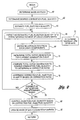
- FIG 2 there is shown a flow diagram illustrating the general sequence of steps associated with the method of the present invention. Although the steps shown in Figure 2 are depicted sequentially, they can be implemented utilising interrupt-driven programming strategies, object-oriented programming, or the like. In a preferred embodiment, the steps shown in Figure 2 comprise a portion of a larger routine which performs other engine control functions.
- the method begins with the step of sensing the air charge via MAF 42, as shown at block 60.
- an estimated fuel injection quantity is determined, as shown at block 64.
- This quantity is estimated utilising either the iterative procedure or the closed-loop algorithm. Illustrated in Figure 2 is the iterative procedure.
- the best estimate for the fuel injection quantity is the previous value of injection fuel, as calculated for the previous cylinder (not the same as the previous value for the current cylinder).
- the estimated fuel injection quantity is then parsed into a predetermined number of liquid components, as shown at block 66.
- This multi-component transient injection fuel control method considers the vaporisation of the full range of fuel components, from the low boiling point fractions, to the highest boiling point fraction. This method recognises that the vaporisation process is occurring at many different locations within the engine, from the location of injection, to the cylinder walls and crank case. Other transient control methods consider only a singular wall wetting history and/or a single evaporation time constant.
- the overall thermal environment of the engine is estimated and applied to calculate the vaporisation rate constants for the different boiling-point fractions of the fuel.
- This method recognises that the low boiling point liquid fractions have a short residence time in the engine, and that the highest boiling liquid fractions have a significantly longer residence time in the engine. Residence time is defined as the time from port injection to the time when there is significant impact on measured variables, such as exhaust A/F ratio.
- the fuel should be subdivided into at least three, preferably five, different boiling point fractions, each of which has a different set of vaporisation time constants as a function of the engine thermal environment.
- This composition parsing function is calibratable for the expected fuel for the vehicle.
- a cold start is that the engine was fully warm and lightly loaded prior to the shutdown. Therefore, the liquid components should be fully depleted, especially if a 12-hour soak preceded the cold start.
- a second possibility for a cold start is the case of a stall following only two seconds of cold operation. In this case for the restart, the liquid components have significantly more mass and higher vaporisation rates. As long as the liquid component mass values are kept in memory between the stall and the restart (comparing cases of equal EEC Load), the gasoline vaporisation model will calculate less injection fuel following the restart.
- the liquid component values at the time of shutdown need to be stored in KAM 19.
- an anti-stall fuzzy logic strategy could modify the size of the liquid component if lean or rich fuelling is suspected.
- input from a fast-light-off HEGO sensor can be used to modify the values of the liquid component masses. If leanness is indicated during the time period of 5-10 seconds after a cold start, then the liquid component sizes need immediate reduction, which would result in the calculation of higher injection fuel quantity.
- the method proceeds to block 68 in which the vaporisation from each liquid component is estimated.
- An essential element of the present invention is the estimation of vapour generation from all sources, i.e., from the injection event to the combustion event. This is simulated by assuming the five liquid components have significantly different vaporisation rate constants. The vaporisation rate constants are assumed to be a function of an estimated temperature of the engine, as shown at block 70.
- Liquid vaporisation rates can be characterised as an exponential function of the liquid temperature. This temperature dependency is assumed to be different for the five liquid components consisting of different boiling-point components. Functions are given below for the temperature dependency of the vaporisation rate constants for the five liquid components. Since these rate constants change slowly as the engine thermal environment changes, these functions can be evaluated in a background routine, with an accuracy of about five percent.
- a temperature scale must be chosen to apply the functions for the vaporisation rate constants.
- the temperature should relate to the energy state of the engine, which influences liquid vaporisation.
- An arbitrary absolute temperature scale is chosen with 1.0 representing the coldest possible metal temperatures of, for example, a cold soak at -40°F. At this temperature, the heaviest gasoline components will not vaporise. The lightest gasoline components are assumed to have a delay through the engine.
- a temperature scale of 2.0 can represent, for example, 4000 RPM, EEC Load of 0.6, and an engine coolant temperature of 240°F.
- the temperature scale should be related to the coolant temperature, and should be increased by a factor relating to the cumulative combustion energy release for the past 5-30 seconds. From engine mapping experience, it is known that more than five minutes are required to stabilise engine temperatures, following a transition to a different speed load condition.
- ATS .00255*(460+ECT+k_heat*Sum over all events per cylinder, during the last 20 seconds, of EEC Load per event), where,
- the total vapour generation is then compared to the desired combustion fuel quantity to determine a corrective ratio, as shown at block 74.
- This predictor-corrector type of iterative method to calculate the injection fuel quantity is stable because the corrective ratio is close to 1.0. Also, the starting value of the injection quantity is the last value for the previous cylinder, and only small changes are expected between successive combustion events.
- the error criteria should be one percent of the desired combustion fuel quantity. That is, if (1+0.01) ⁇ Mvap_ratio ⁇ (1-0.01), then return to block 66. This iterative process may be kept to a predetermined maximum such as, for example, 5 iterations.
- the method proceeds to control the injection fuel quantity, as shown at block 80.
- the calculated injection fuel quantity is output to the injector driver routine for the correct injector.
- the masses of the liquid components are updated due to vaporisation, as shown at block 82.
- the iterative procedure of the present invention requires stored values for "old" values of the size of each of the liquid components.
- the saved value of each liquid component mass is equivalent to the old saved value for the current cylinder, plus an addition from the injection event, minus the mass vaporised during the current combustion event.
- a closed-form type of control algorithm may be used to determine the corrected fuel injection quantity.
- Vaporisation rate constants are assigned to the five different liquid components. The rates are defined, for the current combustion event, as a fraction of the liquid in the given component which vaporises during the current combustion event. As the boiling point increases for successive liquid components, the vaporisation rate constants get smaller. For cold engine conditions, all five VRC(i)'s are much smaller than 1.0. For very hot engine conditions, all five VRC(i)'s can approach the value 1.0. For a cold start at 70°F, the VRC(i) for the "lightest" gasoline component (higher boiling point) may approach the value 1.0.
- the control problem is to calculate the injected fuel mass, such that the total vapour is equal to the desired combustion fuel quantity.
- the divisor (sum of products, P(i)*VRC(i) ), is completed in a background routine.
- the vaporisation calculation, the summing, and the calculation of injection fuel quantity are completed in a foreground routine.
- New_Liquid(i) Old_Liquid(i) - VRC(i) * Old_Liquid(i) + Qf_inj * P(i) - Qf_inj * P(i) * VRC(i)
- New liquid(i) Old liquid(i) - (vapour from old liquid(i) ) + Qf_inj * [ P(i) * (1 - Vapour rate constant (i) ) where the values in brackets, [ P(i) * (1 - Vapour rate constant (i) ) ], is completed in a background routine.
- the method of the present invention is essentially several different single-time constant models acting in parallel. While a single-time constant model, such as the X-Tau model, has a closed solution, this method includes an iterative procedure to calculate the correct injection fuel quantity based on an estimate of vaporisation from the various boiling point components of gasoline. By separating the vaporisation prediction into five parts, the effect of the thermal state of the engine on the liquid components can be predicted separately. During engine transients, especially cold transients, the present invention accounts for vaporisation dynamics from the different liquid components so to provide the desired combustion A/F ratio.
- a single-time constant model such as the X-Tau model
Landscapes
- Engineering & Computer Science (AREA)
- Chemical & Material Sciences (AREA)
- Combustion & Propulsion (AREA)
- Mechanical Engineering (AREA)
- General Engineering & Computer Science (AREA)
- Electrical Control Of Air Or Fuel Supplied To Internal-Combustion Engine (AREA)
- Combined Controls Of Internal Combustion Engines (AREA)
Applications Claiming Priority (2)
| Application Number | Priority Date | Filing Date | Title |
|---|---|---|---|
| US144150 | 1988-01-15 | ||
| US09/144,150 US6067965A (en) | 1998-08-31 | 1998-08-31 | Method and system for determining a quantity of fuel to be injected into an internal combustion engine |
Publications (3)
| Publication Number | Publication Date |
|---|---|
| EP0984148A2 true EP0984148A2 (fr) | 2000-03-08 |
| EP0984148A3 EP0984148A3 (fr) | 2003-01-15 |
| EP0984148B1 EP0984148B1 (fr) | 2006-12-20 |
Family
ID=22507301
Family Applications (1)
| Application Number | Title | Priority Date | Filing Date |
|---|---|---|---|
| EP99306793A Expired - Lifetime EP0984148B1 (fr) | 1998-08-31 | 1999-08-27 | Système et méthode d'alimentation en carburant |
Country Status (3)
| Country | Link |
|---|---|
| US (1) | US6067965A (fr) |
| EP (1) | EP0984148B1 (fr) |
| DE (1) | DE69934460T2 (fr) |
Cited By (2)
| Publication number | Priority date | Publication date | Assignee | Title |
|---|---|---|---|---|
| EP1195509A3 (fr) * | 2000-10-04 | 2004-09-22 | Toyota Jidosha Kabushiki Kaisha | Appareil de commande d'injection de carburant, méthode de commande, et programme de gestion de moteur à combustion interne |
| WO2011049981A3 (fr) * | 2009-10-19 | 2011-10-06 | Nuvera Fuel Cells, Inc. | Systèmes et procédés de gestion de ravitaillement |
Families Citing this family (16)
| Publication number | Priority date | Publication date | Assignee | Title |
|---|---|---|---|---|
| JP3460593B2 (ja) * | 1998-09-17 | 2003-10-27 | 株式会社デンソー | 車両用制御装置 |
| US6257206B1 (en) * | 2000-02-02 | 2001-07-10 | Ford Global Technologies, Inc. | System for controlling air-fuel ratio during intake control device transitions |
| US6539299B2 (en) | 2000-02-18 | 2003-03-25 | Optimum Power Technology | Apparatus and method for calibrating an engine management system |
| JP2001342885A (ja) * | 2000-05-31 | 2001-12-14 | Denso Corp | 内燃機関の燃料噴射制御装置 |
| US6644286B2 (en) | 2001-11-09 | 2003-11-11 | Ford Global Technologies, Llc | Method and system for controlling fuel delivery during transient engine conditions |
| US6460513B1 (en) | 2001-11-27 | 2002-10-08 | Ford Global Technologies, Inc. | Method to adapt engine fuel control, by multi-component vaporization method, to actual volatility quality of fuel |
| US6568246B1 (en) | 2002-01-11 | 2003-05-27 | Ford Global Technologies, L.L.C. | System and method for detecting an air leak in an exhaust system coupled to an engine |
| US6684869B2 (en) | 2002-01-11 | 2004-02-03 | Ford Global Technologies, Llc | System and method for detecting an air leak in an engine |
| US6935311B2 (en) | 2002-10-09 | 2005-08-30 | Ford Global Technologies, Llc | Engine control with fuel quality sensor |
| EP1457653B1 (fr) * | 2003-03-11 | 2009-04-15 | Nissan Motor Co., Ltd. | Commande d'injection de carburant pour moteur |
| US6990968B2 (en) * | 2003-07-24 | 2006-01-31 | Nissan Motor Co., Ltd. | Engine fuel injection amount control device |
| US7111593B2 (en) * | 2004-01-29 | 2006-09-26 | Ford Global Technologies, Llc | Engine control to compensate for fueling dynamics |
| FR2923864B1 (fr) * | 2007-11-20 | 2010-02-26 | Renault Sas | Procede pour diagnostiquer l'etat d'un systeme d'alimentation en carburant d'un moteur. |
| FR2923863B1 (fr) * | 2007-11-20 | 2010-02-26 | Renault Sas | Procede pour diagnostiquer l'etat d'un systeme d'alimentation en carburant d'un moteur. |
| US8447456B2 (en) * | 2008-01-17 | 2013-05-21 | GM Global Technology Operations LLC | Detection of engine intake manifold air-leaks |
| US9915212B2 (en) | 2016-03-10 | 2018-03-13 | Caterpillar Inc. | Engine system having unknown-fuel startup strategy |
Family Cites Families (11)
| Publication number | Priority date | Publication date | Assignee | Title |
|---|---|---|---|---|
| US4939658A (en) * | 1984-09-03 | 1990-07-03 | Hitachi, Ltd. | Control method for a fuel injection engine |
| JPH0323339A (ja) * | 1989-06-20 | 1991-01-31 | Mazda Motor Corp | エンジンの燃料制御装置 |
| JPH0392557A (ja) * | 1989-09-04 | 1991-04-17 | Hitachi Ltd | エンジンの燃料噴射制御方法 |
| JPH05296084A (ja) * | 1992-04-16 | 1993-11-09 | Fuji Heavy Ind Ltd | エンジンの燃料噴射量制御方法 |
| GB9222328D0 (en) * | 1992-10-23 | 1992-12-09 | Lucas Ind Plc | Method of and apparatus for fuelling an internal combustion engine |
| JPH06264808A (ja) * | 1993-03-16 | 1994-09-20 | Mazda Motor Corp | エンジンの制御装置 |
| JPH06323181A (ja) * | 1993-05-14 | 1994-11-22 | Hitachi Ltd | 内燃機関の燃料制御方法及びその装置 |
| US5520153A (en) * | 1995-04-28 | 1996-05-28 | Saturn Corporation | Internal combustion engine control |
| US5584277A (en) * | 1995-09-26 | 1996-12-17 | Chrysler Corporation | Fuel delivery system with wall wetting history and transient control |
| US5642722A (en) * | 1995-10-30 | 1997-07-01 | Motorola Inc. | Adaptive transient fuel compensation for a spark ignited engine |
| US5746183A (en) * | 1997-07-02 | 1998-05-05 | Ford Global Technologies, Inc. | Method and system for controlling fuel delivery during transient engine conditions |
-
1998
- 1998-08-31 US US09/144,150 patent/US6067965A/en not_active Expired - Fee Related
-
1999
- 1999-08-27 DE DE69934460T patent/DE69934460T2/de not_active Expired - Fee Related
- 1999-08-27 EP EP99306793A patent/EP0984148B1/fr not_active Expired - Lifetime
Cited By (2)
| Publication number | Priority date | Publication date | Assignee | Title |
|---|---|---|---|---|
| EP1195509A3 (fr) * | 2000-10-04 | 2004-09-22 | Toyota Jidosha Kabushiki Kaisha | Appareil de commande d'injection de carburant, méthode de commande, et programme de gestion de moteur à combustion interne |
| WO2011049981A3 (fr) * | 2009-10-19 | 2011-10-06 | Nuvera Fuel Cells, Inc. | Systèmes et procédés de gestion de ravitaillement |
Also Published As
| Publication number | Publication date |
|---|---|
| DE69934460T2 (de) | 2007-09-27 |
| US6067965A (en) | 2000-05-30 |
| DE69934460D1 (de) | 2007-02-01 |
| EP0984148A3 (fr) | 2003-01-15 |
| EP0984148B1 (fr) | 2006-12-20 |
Similar Documents
| Publication | Publication Date | Title |
|---|---|---|
| US6067965A (en) | Method and system for determining a quantity of fuel to be injected into an internal combustion engine | |
| US5746183A (en) | Method and system for controlling fuel delivery during transient engine conditions | |
| US5353768A (en) | Fuel control system with compensation for intake valve and engine coolant temperature warm-up rates | |
| US6474308B2 (en) | Apparatus for detecting fuel property for internal combustion engine | |
| US4465051A (en) | Device for intake air temperature-dependent correction of air/fuel ratio for internal combustion engines | |
| US20090107441A1 (en) | Adaptive fuel control strategy for engine starting | |
| US6176222B1 (en) | Engine fuel injection control method with fuel puddle modeling | |
| JPH06235347A (ja) | 内燃機関の燃料性状検出装置 | |
| US4765301A (en) | Fuel supply control method for internal combustion engines after starting | |
| US5743244A (en) | Fuel control method and system with on-line learning of open-loop fuel compensation parameters | |
| GB2382668A (en) | Fuel supply control means for an internal combustion engine | |
| US5144933A (en) | Wall flow learning method and device for fuel supply control system of internal combustion engine | |
| US20050056260A1 (en) | Method and apparatus for predicting a fuel injector tip temperature | |
| JPH04159432A (ja) | 電子制御燃料噴射装置 | |
| US6053036A (en) | Fuel supply amount control system for internal combustion engines | |
| US5735249A (en) | Method and system for controlling fuel delivery during engine cranking | |
| US5263455A (en) | Fuel injection control apparatus for internal combustion engine | |
| US6848427B2 (en) | Method and system for providing fuel injection time scheduling for internal combustion engines using engine speed prediction | |
| JP2006144584A (ja) | 内燃機関の燃料噴射制御装置 | |
| JPH06101522A (ja) | 内燃エンジンの制御装置 | |
| US11261810B2 (en) | Method of controlling engine cold restart | |
| JPH11218043A (ja) | 内燃機関の燃料噴射量制御装置 | |
| JP4706487B2 (ja) | 内燃機関の燃料噴射制御装置 | |
| JP3404911B2 (ja) | エンジンの空燃比制御装置 | |
| JP3240780B2 (ja) | 内燃機関の燃料供給量制御装置 |
Legal Events
| Date | Code | Title | Description |
|---|---|---|---|
| PUAI | Public reference made under article 153(3) epc to a published international application that has entered the european phase |
Free format text: ORIGINAL CODE: 0009012 |
|
| AK | Designated contracting states |
Kind code of ref document: A2 Designated state(s): AT BE CH CY DE DK ES FI FR GB GR IE IT LI LU MC NL PT SE |
|
| AX | Request for extension of the european patent |
Free format text: AL;LT;LV;MK;RO;SI |
|
| PUAL | Search report despatched |
Free format text: ORIGINAL CODE: 0009013 |
|
| AK | Designated contracting states |
Kind code of ref document: A3 Designated state(s): AT BE CH CY DE DK ES FI FR GB GR IE IT LI LU MC NL PT SE |
|
| AX | Request for extension of the european patent |
Free format text: AL;LT;LV;MK;RO;SI |
|
| RIC1 | Information provided on ipc code assigned before grant |
Free format text: 7F 02D 43/00 A, 7F 02M 25/08 B, 7F 02D 41/14 B, 7F 02D 41/04 B, 7F 02D 41/18 B, 7F 02D 41/32 B |
|
| 17P | Request for examination filed |
Effective date: 20030613 |
|
| AKX | Designation fees paid |
Designated state(s): DE FR GB |
|
| GRAP | Despatch of communication of intention to grant a patent |
Free format text: ORIGINAL CODE: EPIDOSNIGR1 |
|
| GRAS | Grant fee paid |
Free format text: ORIGINAL CODE: EPIDOSNIGR3 |
|
| GRAA | (expected) grant |
Free format text: ORIGINAL CODE: 0009210 |
|
| AK | Designated contracting states |
Kind code of ref document: B1 Designated state(s): DE FR GB |
|
| REG | Reference to a national code |
Ref country code: GB Ref legal event code: FG4D |
|
| REF | Corresponds to: |
Ref document number: 69934460 Country of ref document: DE Date of ref document: 20070201 Kind code of ref document: P |
|
| REG | Reference to a national code |
Ref country code: GB Ref legal event code: 732E |
|
| EN | Fr: translation not filed | ||
| PGFP | Annual fee paid to national office [announced via postgrant information from national office to epo] |
Ref country code: DE Payment date: 20070831 Year of fee payment: 9 |
|
| PLBE | No opposition filed within time limit |
Free format text: ORIGINAL CODE: 0009261 |
|
| STAA | Information on the status of an ep patent application or granted ep patent |
Free format text: STATUS: NO OPPOSITION FILED WITHIN TIME LIMIT |
|
| 26N | No opposition filed |
Effective date: 20070921 |
|
| PGFP | Annual fee paid to national office [announced via postgrant information from national office to epo] |
Ref country code: GB Payment date: 20070705 Year of fee payment: 9 |
|
| PG25 | Lapsed in a contracting state [announced via postgrant information from national office to epo] |
Ref country code: FR Free format text: LAPSE BECAUSE OF FAILURE TO SUBMIT A TRANSLATION OF THE DESCRIPTION OR TO PAY THE FEE WITHIN THE PRESCRIBED TIME-LIMIT Effective date: 20070810 |
|
| PG25 | Lapsed in a contracting state [announced via postgrant information from national office to epo] |
Ref country code: FR Free format text: LAPSE BECAUSE OF FAILURE TO SUBMIT A TRANSLATION OF THE DESCRIPTION OR TO PAY THE FEE WITHIN THE PRESCRIBED TIME-LIMIT Effective date: 20061220 |
|
| GBPC | Gb: european patent ceased through non-payment of renewal fee |
Effective date: 20080827 |
|
| PG25 | Lapsed in a contracting state [announced via postgrant information from national office to epo] |
Ref country code: DE Free format text: LAPSE BECAUSE OF NON-PAYMENT OF DUE FEES Effective date: 20090303 |
|
| PG25 | Lapsed in a contracting state [announced via postgrant information from national office to epo] |
Ref country code: GB Free format text: LAPSE BECAUSE OF NON-PAYMENT OF DUE FEES Effective date: 20080827 |