EP0995621B1 - Système de conditionnement d'air pour véhicule - Google Patents
Système de conditionnement d'air pour véhicule Download PDFInfo
- Publication number
- EP0995621B1 EP0995621B1 EP99120100A EP99120100A EP0995621B1 EP 0995621 B1 EP0995621 B1 EP 0995621B1 EP 99120100 A EP99120100 A EP 99120100A EP 99120100 A EP99120100 A EP 99120100A EP 0995621 B1 EP0995621 B1 EP 0995621B1
- Authority
- EP
- European Patent Office
- Prior art keywords
- air
- evaporator
- cold
- temperature
- mode
- Prior art date
- Legal status (The legal status is an assumption and is not a legal conclusion. Google has not performed a legal analysis and makes no representation as to the accuracy of the status listed.)
- Expired - Lifetime
Links
Images













Classifications
-
- B—PERFORMING OPERATIONS; TRANSPORTING
- B60—VEHICLES IN GENERAL
- B60H—ARRANGEMENTS OF HEATING, COOLING, VENTILATING OR OTHER AIR-TREATING DEVICES SPECIALLY ADAPTED FOR PASSENGER OR GOODS SPACES OF VEHICLES
- B60H1/00—Heating, cooling or ventilating devices
- B60H1/32—Cooling devices
- B60H1/3204—Cooling devices using compression
- B60H1/3205—Control means therefor
- B60H1/322—Control means therefor for improving the stop or idling operation of the engine
-
- B—PERFORMING OPERATIONS; TRANSPORTING
- B60—VEHICLES IN GENERAL
- B60H—ARRANGEMENTS OF HEATING, COOLING, VENTILATING OR OTHER AIR-TREATING DEVICES SPECIALLY ADAPTED FOR PASSENGER OR GOODS SPACES OF VEHICLES
- B60H1/00—Heating, cooling or ventilating devices
- B60H1/00492—Heating, cooling or ventilating devices comprising regenerative heating or cooling means, e.g. heat accumulators
- B60H1/005—Regenerative cooling means, e.g. cold accumulators
-
- B—PERFORMING OPERATIONS; TRANSPORTING
- B60—VEHICLES IN GENERAL
- B60H—ARRANGEMENTS OF HEATING, COOLING, VENTILATING OR OTHER AIR-TREATING DEVICES SPECIALLY ADAPTED FOR PASSENGER OR GOODS SPACES OF VEHICLES
- B60H1/00—Heating, cooling or ventilating devices
- B60H1/00642—Control systems or circuits; Control members or indication devices for heating, cooling or ventilating devices
- B60H1/00735—Control systems or circuits characterised by their input, i.e. by the detection, measurement or calculation of particular conditions, e.g. signal treatment, dynamic models
- B60H1/00764—Control systems or circuits characterised by their input, i.e. by the detection, measurement or calculation of particular conditions, e.g. signal treatment, dynamic models the input being a vehicle driving condition, e.g. speed
- B60H1/00778—Control systems or circuits characterised by their input, i.e. by the detection, measurement or calculation of particular conditions, e.g. signal treatment, dynamic models the input being a vehicle driving condition, e.g. speed the input being a stationary vehicle position, e.g. parking or stopping
-
- B—PERFORMING OPERATIONS; TRANSPORTING
- B60—VEHICLES IN GENERAL
- B60H—ARRANGEMENTS OF HEATING, COOLING, VENTILATING OR OTHER AIR-TREATING DEVICES SPECIALLY ADAPTED FOR PASSENGER OR GOODS SPACES OF VEHICLES
- B60H1/00—Heating, cooling or ventilating devices
- B60H1/00642—Control systems or circuits; Control members or indication devices for heating, cooling or ventilating devices
- B60H1/00814—Control systems or circuits characterised by their output, for controlling particular components of the heating, cooling or ventilating installation
- B60H1/00878—Control systems or circuits characterised by their output, for controlling particular components of the heating, cooling or ventilating installation the components being temperature regulating devices
- B60H1/00885—Controlling the flow of heating or cooling liquid, e.g. valves or pumps
-
- B—PERFORMING OPERATIONS; TRANSPORTING
- B60—VEHICLES IN GENERAL
- B60H—ARRANGEMENTS OF HEATING, COOLING, VENTILATING OR OTHER AIR-TREATING DEVICES SPECIALLY ADAPTED FOR PASSENGER OR GOODS SPACES OF VEHICLES
- B60H1/00—Heating, cooling or ventilating devices
- B60H1/32—Cooling devices
- B60H1/3204—Cooling devices using compression
- B60H1/3205—Control means therefor
-
- B—PERFORMING OPERATIONS; TRANSPORTING
- B60—VEHICLES IN GENERAL
- B60H—ARRANGEMENTS OF HEATING, COOLING, VENTILATING OR OTHER AIR-TREATING DEVICES SPECIALLY ADAPTED FOR PASSENGER OR GOODS SPACES OF VEHICLES
- B60H1/00—Heating, cooling or ventilating devices
- B60H1/32—Cooling devices
- B60H1/3204—Cooling devices using compression
- B60H1/3205—Control means therefor
- B60H1/3211—Control means therefor for increasing the efficiency of a vehicle refrigeration cycle
-
- B—PERFORMING OPERATIONS; TRANSPORTING
- B60—VEHICLES IN GENERAL
- B60H—ARRANGEMENTS OF HEATING, COOLING, VENTILATING OR OTHER AIR-TREATING DEVICES SPECIALLY ADAPTED FOR PASSENGER OR GOODS SPACES OF VEHICLES
- B60H1/00—Heating, cooling or ventilating devices
- B60H1/32—Cooling devices
- B60H1/3204—Cooling devices using compression
- B60H1/3205—Control means therefor
- B60H1/3216—Control means therefor for improving a change in operation duty of a compressor in a vehicle
-
- F—MECHANICAL ENGINEERING; LIGHTING; HEATING; WEAPONS; BLASTING
- F25—REFRIGERATION OR COOLING; COMBINED HEATING AND REFRIGERATION SYSTEMS; HEAT PUMP SYSTEMS; MANUFACTURE OR STORAGE OF ICE; LIQUEFACTION SOLIDIFICATION OF GASES
- F25B—REFRIGERATION MACHINES, PLANTS OR SYSTEMS; COMBINED HEATING AND REFRIGERATION SYSTEMS; HEAT PUMP SYSTEMS
- F25B41/00—Fluid-circulation arrangements
- F25B41/30—Expansion means; Dispositions thereof
- F25B41/31—Expansion valves
- F25B41/34—Expansion valves with the valve member being actuated by electric means, e.g. by piezoelectric actuators
- F25B41/345—Expansion valves with the valve member being actuated by electric means, e.g. by piezoelectric actuators by solenoids
-
- F—MECHANICAL ENGINEERING; LIGHTING; HEATING; WEAPONS; BLASTING
- F25—REFRIGERATION OR COOLING; COMBINED HEATING AND REFRIGERATION SYSTEMS; HEAT PUMP SYSTEMS; MANUFACTURE OR STORAGE OF ICE; LIQUEFACTION SOLIDIFICATION OF GASES
- F25B—REFRIGERATION MACHINES, PLANTS OR SYSTEMS; COMBINED HEATING AND REFRIGERATION SYSTEMS; HEAT PUMP SYSTEMS
- F25B41/00—Fluid-circulation arrangements
- F25B41/30—Expansion means; Dispositions thereof
- F25B41/31—Expansion valves
- F25B41/34—Expansion valves with the valve member being actuated by electric means, e.g. by piezoelectric actuators
- F25B41/35—Expansion valves with the valve member being actuated by electric means, e.g. by piezoelectric actuators by rotary motors, e.g. by stepping motors
-
- B—PERFORMING OPERATIONS; TRANSPORTING
- B60—VEHICLES IN GENERAL
- B60H—ARRANGEMENTS OF HEATING, COOLING, VENTILATING OR OTHER AIR-TREATING DEVICES SPECIALLY ADAPTED FOR PASSENGER OR GOODS SPACES OF VEHICLES
- B60H1/00—Heating, cooling or ventilating devices
- B60H1/00642—Control systems or circuits; Control members or indication devices for heating, cooling or ventilating devices
- B60H1/00814—Control systems or circuits characterised by their output, for controlling particular components of the heating, cooling or ventilating installation
- B60H1/00878—Control systems or circuits characterised by their output, for controlling particular components of the heating, cooling or ventilating installation the components being temperature regulating devices
- B60H2001/00961—Control systems or circuits characterised by their output, for controlling particular components of the heating, cooling or ventilating installation the components being temperature regulating devices comprising means for defrosting outside heat exchangers
-
- B—PERFORMING OPERATIONS; TRANSPORTING
- B60—VEHICLES IN GENERAL
- B60H—ARRANGEMENTS OF HEATING, COOLING, VENTILATING OR OTHER AIR-TREATING DEVICES SPECIALLY ADAPTED FOR PASSENGER OR GOODS SPACES OF VEHICLES
- B60H1/00—Heating, cooling or ventilating devices
- B60H1/32—Cooling devices
- B60H2001/3236—Cooling devices information from a variable is obtained
- B60H2001/3244—Cooling devices information from a variable is obtained related to humidity
-
- B—PERFORMING OPERATIONS; TRANSPORTING
- B60—VEHICLES IN GENERAL
- B60H—ARRANGEMENTS OF HEATING, COOLING, VENTILATING OR OTHER AIR-TREATING DEVICES SPECIALLY ADAPTED FOR PASSENGER OR GOODS SPACES OF VEHICLES
- B60H1/00—Heating, cooling or ventilating devices
- B60H1/32—Cooling devices
- B60H2001/3236—Cooling devices information from a variable is obtained
- B60H2001/3244—Cooling devices information from a variable is obtained related to humidity
- B60H2001/3245—Cooling devices information from a variable is obtained related to humidity of air
-
- B—PERFORMING OPERATIONS; TRANSPORTING
- B60—VEHICLES IN GENERAL
- B60H—ARRANGEMENTS OF HEATING, COOLING, VENTILATING OR OTHER AIR-TREATING DEVICES SPECIALLY ADAPTED FOR PASSENGER OR GOODS SPACES OF VEHICLES
- B60H1/00—Heating, cooling or ventilating devices
- B60H1/32—Cooling devices
- B60H2001/3236—Cooling devices information from a variable is obtained
- B60H2001/3255—Cooling devices information from a variable is obtained related to temperature
-
- B—PERFORMING OPERATIONS; TRANSPORTING
- B60—VEHICLES IN GENERAL
- B60H—ARRANGEMENTS OF HEATING, COOLING, VENTILATING OR OTHER AIR-TREATING DEVICES SPECIALLY ADAPTED FOR PASSENGER OR GOODS SPACES OF VEHICLES
- B60H1/00—Heating, cooling or ventilating devices
- B60H1/32—Cooling devices
- B60H2001/3236—Cooling devices information from a variable is obtained
- B60H2001/3255—Cooling devices information from a variable is obtained related to temperature
- B60H2001/3261—Cooling devices information from a variable is obtained related to temperature of the air at an evaporating unit
-
- B—PERFORMING OPERATIONS; TRANSPORTING
- B60—VEHICLES IN GENERAL
- B60H—ARRANGEMENTS OF HEATING, COOLING, VENTILATING OR OTHER AIR-TREATING DEVICES SPECIALLY ADAPTED FOR PASSENGER OR GOODS SPACES OF VEHICLES
- B60H1/00—Heating, cooling or ventilating devices
- B60H1/32—Cooling devices
- B60H2001/3236—Cooling devices information from a variable is obtained
- B60H2001/3255—Cooling devices information from a variable is obtained related to temperature
- B60H2001/3263—Cooling devices information from a variable is obtained related to temperature of the refrigerant at an evaporating unit
-
- B—PERFORMING OPERATIONS; TRANSPORTING
- B60—VEHICLES IN GENERAL
- B60H—ARRANGEMENTS OF HEATING, COOLING, VENTILATING OR OTHER AIR-TREATING DEVICES SPECIALLY ADAPTED FOR PASSENGER OR GOODS SPACES OF VEHICLES
- B60H1/00—Heating, cooling or ventilating devices
- B60H1/32—Cooling devices
- B60H2001/3236—Cooling devices information from a variable is obtained
- B60H2001/3266—Cooling devices information from a variable is obtained related to the operation of the vehicle
-
- B—PERFORMING OPERATIONS; TRANSPORTING
- B60—VEHICLES IN GENERAL
- B60H—ARRANGEMENTS OF HEATING, COOLING, VENTILATING OR OTHER AIR-TREATING DEVICES SPECIALLY ADAPTED FOR PASSENGER OR GOODS SPACES OF VEHICLES
- B60H1/00—Heating, cooling or ventilating devices
- B60H1/32—Cooling devices
- B60H2001/3236—Cooling devices information from a variable is obtained
- B60H2001/3267—Cooling devices information from a variable is obtained related to the operation of an expansion valve
-
- B—PERFORMING OPERATIONS; TRANSPORTING
- B60—VEHICLES IN GENERAL
- B60H—ARRANGEMENTS OF HEATING, COOLING, VENTILATING OR OTHER AIR-TREATING DEVICES SPECIALLY ADAPTED FOR PASSENGER OR GOODS SPACES OF VEHICLES
- B60H1/00—Heating, cooling or ventilating devices
- B60H1/32—Cooling devices
- B60H2001/3269—Cooling devices output of a control signal
-
- B—PERFORMING OPERATIONS; TRANSPORTING
- B60—VEHICLES IN GENERAL
- B60H—ARRANGEMENTS OF HEATING, COOLING, VENTILATING OR OTHER AIR-TREATING DEVICES SPECIALLY ADAPTED FOR PASSENGER OR GOODS SPACES OF VEHICLES
- B60H1/00—Heating, cooling or ventilating devices
- B60H1/32—Cooling devices
- B60H2001/3269—Cooling devices output of a control signal
- B60H2001/327—Cooling devices output of a control signal related to a compressing unit
-
- B—PERFORMING OPERATIONS; TRANSPORTING
- B60—VEHICLES IN GENERAL
- B60H—ARRANGEMENTS OF HEATING, COOLING, VENTILATING OR OTHER AIR-TREATING DEVICES SPECIALLY ADAPTED FOR PASSENGER OR GOODS SPACES OF VEHICLES
- B60H1/00—Heating, cooling or ventilating devices
- B60H1/32—Cooling devices
- B60H2001/3269—Cooling devices output of a control signal
- B60H2001/328—Cooling devices output of a control signal related to an evaporating unit
-
- B—PERFORMING OPERATIONS; TRANSPORTING
- B60—VEHICLES IN GENERAL
- B60H—ARRANGEMENTS OF HEATING, COOLING, VENTILATING OR OTHER AIR-TREATING DEVICES SPECIALLY ADAPTED FOR PASSENGER OR GOODS SPACES OF VEHICLES
- B60H1/00—Heating, cooling or ventilating devices
- B60H1/32—Cooling devices
- B60H2001/3269—Cooling devices output of a control signal
- B60H2001/328—Cooling devices output of a control signal related to an evaporating unit
- B60H2001/3282—Cooling devices output of a control signal related to an evaporating unit to control the air flow
-
- B—PERFORMING OPERATIONS; TRANSPORTING
- B60—VEHICLES IN GENERAL
- B60H—ARRANGEMENTS OF HEATING, COOLING, VENTILATING OR OTHER AIR-TREATING DEVICES SPECIALLY ADAPTED FOR PASSENGER OR GOODS SPACES OF VEHICLES
- B60H1/00—Heating, cooling or ventilating devices
- B60H1/32—Cooling devices
- B60H2001/3269—Cooling devices output of a control signal
- B60H2001/3285—Cooling devices output of a control signal related to an expansion unit
-
- F—MECHANICAL ENGINEERING; LIGHTING; HEATING; WEAPONS; BLASTING
- F25—REFRIGERATION OR COOLING; COMBINED HEATING AND REFRIGERATION SYSTEMS; HEAT PUMP SYSTEMS; MANUFACTURE OR STORAGE OF ICE; LIQUEFACTION SOLIDIFICATION OF GASES
- F25B—REFRIGERATION MACHINES, PLANTS OR SYSTEMS; COMBINED HEATING AND REFRIGERATION SYSTEMS; HEAT PUMP SYSTEMS
- F25B2341/00—Details of ejectors not being used as compression device; Details of flow restrictors or expansion valves
- F25B2341/06—Details of flow restrictors or expansion valves
- F25B2341/068—Expansion valves combined with a sensor
- F25B2341/0682—Expansion valves combined with a sensor the sensor contains sorbent materials
-
- F—MECHANICAL ENGINEERING; LIGHTING; HEATING; WEAPONS; BLASTING
- F25—REFRIGERATION OR COOLING; COMBINED HEATING AND REFRIGERATION SYSTEMS; HEAT PUMP SYSTEMS; MANUFACTURE OR STORAGE OF ICE; LIQUEFACTION SOLIDIFICATION OF GASES
- F25B—REFRIGERATION MACHINES, PLANTS OR SYSTEMS; COMBINED HEATING AND REFRIGERATION SYSTEMS; HEAT PUMP SYSTEMS
- F25B2341/00—Details of ejectors not being used as compression device; Details of flow restrictors or expansion valves
- F25B2341/06—Details of flow restrictors or expansion valves
- F25B2341/068—Expansion valves combined with a sensor
- F25B2341/0683—Expansion valves combined with a sensor the sensor is disposed in the suction line and influenced by the temperature or the pressure of the suction gas
-
- F—MECHANICAL ENGINEERING; LIGHTING; HEATING; WEAPONS; BLASTING
- F25—REFRIGERATION OR COOLING; COMBINED HEATING AND REFRIGERATION SYSTEMS; HEAT PUMP SYSTEMS; MANUFACTURE OR STORAGE OF ICE; LIQUEFACTION SOLIDIFICATION OF GASES
- F25B—REFRIGERATION MACHINES, PLANTS OR SYSTEMS; COMBINED HEATING AND REFRIGERATION SYSTEMS; HEAT PUMP SYSTEMS
- F25B2400/00—Component parts or details not otherwise provided for in this subclass
- F25B2400/24—Thermal storage element
-
- F—MECHANICAL ENGINEERING; LIGHTING; HEATING; WEAPONS; BLASTING
- F25—REFRIGERATION OR COOLING; COMBINED HEATING AND REFRIGERATION SYSTEMS; HEAT PUMP SYSTEMS; MANUFACTURE OR STORAGE OF ICE; LIQUEFACTION SOLIDIFICATION OF GASES
- F25B—REFRIGERATION MACHINES, PLANTS OR SYSTEMS; COMBINED HEATING AND REFRIGERATION SYSTEMS; HEAT PUMP SYSTEMS
- F25B2600/00—Control issues
- F25B2600/25—Control of valves
- F25B2600/2513—Expansion valves
-
- F—MECHANICAL ENGINEERING; LIGHTING; HEATING; WEAPONS; BLASTING
- F25—REFRIGERATION OR COOLING; COMBINED HEATING AND REFRIGERATION SYSTEMS; HEAT PUMP SYSTEMS; MANUFACTURE OR STORAGE OF ICE; LIQUEFACTION SOLIDIFICATION OF GASES
- F25B—REFRIGERATION MACHINES, PLANTS OR SYSTEMS; COMBINED HEATING AND REFRIGERATION SYSTEMS; HEAT PUMP SYSTEMS
- F25B2700/00—Sensing or detecting of parameters; Sensors therefor
- F25B2700/21—Temperatures
- F25B2700/2117—Temperatures of an evaporator
-
- F—MECHANICAL ENGINEERING; LIGHTING; HEATING; WEAPONS; BLASTING
- F25—REFRIGERATION OR COOLING; COMBINED HEATING AND REFRIGERATION SYSTEMS; HEAT PUMP SYSTEMS; MANUFACTURE OR STORAGE OF ICE; LIQUEFACTION SOLIDIFICATION OF GASES
- F25B—REFRIGERATION MACHINES, PLANTS OR SYSTEMS; COMBINED HEATING AND REFRIGERATION SYSTEMS; HEAT PUMP SYSTEMS
- F25B2700/00—Sensing or detecting of parameters; Sensors therefor
- F25B2700/21—Temperatures
- F25B2700/2117—Temperatures of an evaporator
- F25B2700/21174—Temperatures of an evaporator of the refrigerant at the inlet of the evaporator
-
- F—MECHANICAL ENGINEERING; LIGHTING; HEATING; WEAPONS; BLASTING
- F25—REFRIGERATION OR COOLING; COMBINED HEATING AND REFRIGERATION SYSTEMS; HEAT PUMP SYSTEMS; MANUFACTURE OR STORAGE OF ICE; LIQUEFACTION SOLIDIFICATION OF GASES
- F25B—REFRIGERATION MACHINES, PLANTS OR SYSTEMS; COMBINED HEATING AND REFRIGERATION SYSTEMS; HEAT PUMP SYSTEMS
- F25B49/00—Arrangement or mounting of control or safety devices
- F25B49/02—Arrangement or mounting of control or safety devices for compression type machines, plants or systems
- F25B49/022—Compressor control arrangements
-
- F—MECHANICAL ENGINEERING; LIGHTING; HEATING; WEAPONS; BLASTING
- F25—REFRIGERATION OR COOLING; COMBINED HEATING AND REFRIGERATION SYSTEMS; HEAT PUMP SYSTEMS; MANUFACTURE OR STORAGE OF ICE; LIQUEFACTION SOLIDIFICATION OF GASES
- F25D—REFRIGERATORS; COLD ROOMS; ICE-BOXES; COOLING OR FREEZING APPARATUS NOT OTHERWISE PROVIDED FOR
- F25D16/00—Devices using a combination of a cooling mode associated with refrigerating machinery with a cooling mode not associated with refrigerating machinery
-
- Y—GENERAL TAGGING OF NEW TECHNOLOGICAL DEVELOPMENTS; GENERAL TAGGING OF CROSS-SECTIONAL TECHNOLOGIES SPANNING OVER SEVERAL SECTIONS OF THE IPC; TECHNICAL SUBJECTS COVERED BY FORMER USPC CROSS-REFERENCE ART COLLECTIONS [XRACs] AND DIGESTS
- Y02—TECHNOLOGIES OR APPLICATIONS FOR MITIGATION OR ADAPTATION AGAINST CLIMATE CHANGE
- Y02B—CLIMATE CHANGE MITIGATION TECHNOLOGIES RELATED TO BUILDINGS, e.g. HOUSING, HOUSE APPLIANCES OR RELATED END-USER APPLICATIONS
- Y02B30/00—Energy efficient heating, ventilation or air conditioning [HVAC]
- Y02B30/70—Efficient control or regulation technologies, e.g. for control of refrigerant flow, motor or heating
Definitions
- the present invention relates to a vehicle air-conditioning system having a compressor of a refrigerant cycle, driven by a vehicle engine or an auxiliary driving unit such as an electrical motor.
- the vehicle air-conditioning system improves cooling performance even when operation of the compressor is forcibly temporarily stopped.
- a vehicle such as an eco-run vehicle or a hybrid vehicle, where a vehicle engine automatically stops when the vehicle is halted for example at a traffic signal, is practically used.
- a compressor of a refrigerant cycle is driven by the vehicle engine. Therefore, when the vehicle engine is stopped when the vehicle is halted for example at a traffic signal, temperature of air blown from an evaporator is increased with the compressor stoppage, and temperature of air blown into a passenger compartment is increased.
- the operation of the compressor may be forcibly temporarily stopped by a request from a vehicle engine side. For example, when the vehicle is accelerated, the operation of the compressor is forcibly temporarily stopped so that accelerating performance of the vehicle is improved. In this case, when the operation of the compressor is forcibly temporarily stopped, the temperature of air blown into the passenger compartment is increased, and cooling performance for a passenger in the passenger compartment is deteriorated.
- EP- A-0,656,273 discloses an air conditioning system for a vehicle having a passenger compartment.
- This system comprises an air conditioning case for forming an air passage through which the air flows into the passenger compartment, an evaporator for cooling air in the passage, a compressor for compressing this charging refrigerant having passed through the evaporator, and a control unit for controlling an air conditioning state of the passenger compartment.
- US-A-5 685 162 discloses a vehicle air-conditioning system according to the preamble of claims 1 and 13.
- an object of the present invention to provide an air-conditioning system which prevents cooling performance from being deteriorated when a compressor of a refrigerant cycle is forcibly temporarily stopped.
- an air-conditioning system for a vehicle includes an evaporator for cooling air to be blown into a passenger compartment of the vehicle, a compressor arranged to be driven by a vehicle engine for compressing and discharging refrigerant having passed through the evaporator, and a control unit for controlling air-conditioning state of the passenger compartment.
- the control unit When the engine operates, the control unit performs a cold-storing mode where cold quantity stored in condensed water on the evaporator is increased.
- the control unit performs a cold-releasing mode where air is cooled by cold released from the condensed water on the evaporator.
- the evaporator is disposed in the air-conditioning case to form a bypass passage through which air bypasses the evaporator, an opening degree of the bypass passage is adjusted by a bypass door, and during the cold-storing mode the control unit adjusts temperature of air blown into the passenger compartment by adjusting the opening degree of the bypass passage by using the bypass door. Therefore, even when evaporator temperature is decreased to increase the cold-storing quantity in the condensed water of the evaporator during the cold-storing mode, it is possible to control temperature of air blown into the passenger compartment by mixing air passing through the evaporator and air passing through the bypass passage, and it is possible to reduce air flow amount passing through the evaporator by the air flow amount passing through the bypass passage. Thus, by reducing the air flow amount passing through the evaporator, power consumed in the compressor can be effectively reduced. As a result, the air-conditioning system improves both cool-storing effect in the evaporator and power-saving effect in the compressor.
- a control unit when the compressor operates, a control unit performs a cold-storing mode in which cold quantity stored in condensed water on the evaporator is increased.
- the control unit preferably includes a prohibiting determining unit for determining a prohibiting condition of the cold-storing mode, and the control unit stops the cold-storing mode when the prohibiting condition of the cold-storing mode is determined while the compressor operates.
- an air-conditioning system for a vehicle includes a temperature adjustment unit for adjusting temperature of air to be blown into the passenger compartment at a target temperature, and a control unit for controlling air-conditioning state of the passenger compartment.
- the control unit sets a cold-storing mode where cold stored in condensed water on the evaporator is increased.
- the control unit sets a cold-releasing mode where air passing through the evaporator is cooled by cold released from condensed water of the evaporator.
- the control unit preferably includes a correction unit for correcting the target temperature of air blown into the passenger compartment to a low temperature side based on an increase of humidity of the passenger compartment.
- a correction unit for correcting the target temperature of air blown into the passenger compartment to a low temperature side based on an increase of humidity of the passenger compartment.
- the correction unit corrects the target temperature of air blown into the passenger compartment based on both a correction due to the humidity of the passenger compartment and a correction due to a humidity changing rate of the passenger compartment. Therefore, the humidity sensing level of the passenger is further moved to a high-temperature side relative to the evaporator temperature.
- a control unit of an air-conditioning system preferably includes a cooling degree calculating unit for calculating a limit value of cooling degree of the evaporator in forcibly stopping mode, during the compressor operating. Only when cooling degree of the evaporator is lower than the limit value during the forcibly stopping mode, the compressor is stopped. On the other hand, when the cooling degree of the evaporator is higher than the limit value during the forcibly stopping mode, the control unit outputs a signal for requesting operation of the compressor to the driving unit. Thus, the cold-releasing mode is performed while cooling degree of the evaporator is increased to the limit value. As a result, before unpleasant feeling is given to the passenger, the compressor is operated so that cooling performance can be improved during the cold-releasing mode.
- control unit preferably includes a dehumidification determining unit for determining whether or not it is necessary to dehumidify air in the passenger compartment. Even during the forcibly stopping mode of the compressor, when the dehumidification determining unit determines that it is necessary to dehumidify air in the passenger compartment, the control unit outputs a signal for requesting operation of the compressor to the driving unit.
- the operation of the compressor is restarted to perform air-conditioning in the passenger compartment.
- evaporator temperature is lowered, dehumidifying capacity of evaporator is improved, and defrosting performance of the windshield improved.
- a vehicle air-conditioning system includes an evaporator disposed in the air-conditioning case to form a bypass passage through which air bypasses the evaporator, a bypass door for adjusting an opening degree of the bypass passage, a compressor for compressing and discharging refrigerant having passed through the evaporator, and a control unit for controlling air-conditioning state of the passenger compartment.
- the control unit performs a cold-storing mode where cold stored in condensed water on the evaporator is increased.
- the control unit performs a cold-releasing mode where air is cooled by cold released from condensed water of the evaporator.
- the bypass door opens the bypass passage during the cold-storing mode, and the bypass door is operated to close a part of an air passage of the evaporator so than an air flow resistance is increased in the evaporator when the bypass door opens the bypass passage.
- the air flow resistance of the air passage in the evaporator is increased when the bypass door opens the bypass passage, an arrangement space of the bypass passage and the bypass door is reduced, and sufficient temperature adjusting effect can be obtained without increasing the size of the air-conditioning system.
- power consumption effect of the compressor is improved while a reheating air quantity in a heating heat exchanger at a downstream air side of the evaporator is reduced.
- a refrigerant cycle system includes an evaporator for cooling air passing therethrough, a compressor for compressing and discharging refrigerant having passed through the evaporator, a press-reducing unit for reducing pressure of refrigerant supplying into the evaporator, and a control unit for selectively setting a cooling mode where a cooling temperature of the evaporator is higher than a predetermined temperature and a cold-storing mode where the cooling temperature of the evaporator is lower than the predetermined temperature.
- the press-reducing unit increases a throttle amount as compared with a cooling mode.
- evaporation pressure of refrigerant in the evaporator is forcibly reduced by increasing the throttle amount of the press-reducing unit, and evaporator temperature is lowered to the freezing point at least at a refrigerant inlet side so that cold-storing effect is improved.
- a control unit performs a cold-storing mode where condensed water of the evaporator is frozen and cold quantity stored in condensed water of the evaporator is increased when the compressor operates.
- the control unit includes a first time determining unit for determining cold-storing possible time, based on cooling degree of the evaporator and air state sucked into the evaporator, for which the cold-storing mode is continuously performed. When a time for which the cold-storing mode is performed elapses the cold-storing possible time, the control unit stops the cold-storing mode and performs a defrosting mode for defrosting the evaporator.
- the control unit includes a second time determining unit for determining a necessary defrosting time, based on cooling degree of the evaporator and air state sucked into the evaporator, for which the defrosting mode is continuously performed.
- the control unit stops the defrosting mode for defrosting the evaporator.
- the defrosting mode of the evaporator because a melting speed of frozen condensed water is mainly relative to the cooling degree of the evaporator and the air state sucked into the evaporator, the defrosting of the evaporator can be accurately controlled by setting the necessary defrosting time. Therefore, both air flow decrease due to insufficient defrosting and insufficient cold-storing due to over-defrosting are prevented.
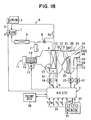
- FIG. 1 is a schematic view of the construction of a vehicle air-conditioning system according to a first preferred embodiment of the present invention.
- a refrigerant cycle R of the air-conditioning system has a compressor 1 for taking in, compressing and discharging refrigerant.
- the compressor 1 has an electromagnetic clutch 2 for power switching, and power from a vehicle engine 4 is transmitted to the compressor 1 via the electromagnetic clutch 2 and a belt 3.
- Electric current supplying to the electromagnetic clutch 2 is switched by an air-conditioning electronic control unit (ECU) 5.
- ECU air-conditioning electronic control unit
- the electromagnetic clutch 2 When electrical current is passed through the electromagnetic clutch 2, the electromagnetic clutch 2 is turned on to drive the compressor 1. Conversely, when electrical current supplying to the electromagnetic clutch 2 is cut off, the electromagnetic clutch 2 is tuned off to stop the operation of the compressor 1.
- High-temperature high-pressure superheated gas refrigerant discharged by the compressor 1 flows into a condenser 6, and the refrigerant is heat-exchanged with outside air blown by a cooling fan (not shown) in the condenser 6 to be cooled and condensed.
- Refrigerant condensed in the condenser 6 then flows into a receiver 7, and is separated into gas refrigerant and liquid refrigerant within the receiver 7 while excess refrigerant (liquid refrigerant) of the refrigerant cycle R is stored in the receiver 7.
- Liquid refrigerant from the receiver 7 is reduced in pressure to a low pressure by an expansion valve (pressure-reducing unit) 8, and becomes in a low-pressure gas/liquid two-phase state.
- Low-pressure refrigerant from the expansion valve 8 flows into an evaporator (i.e., heat exchanger for cooling) 9.
- the evaporator 9 is disposed inside an air-conditioning case 10 of the vehicle air-conditioning system, and low-pressure refrigerant flowing into the evaporator 9 absorbs heat from air inside the air-conditioning case 10 and evaporates.
- the expansion valve 8 is a thermal type expansion valve having a temperature-sensing part 8a for sensing the temperature of refrigerant at an outlet of the evaporator 9, and adjusts its valve opening degree (refrigerant flow) so that a degree of superheating of the refrigerant at the outlet of the evaporator 9 is maintained at a predetermined value.
- the refrigerant outlet of the evaporator 9 is connected to an intake side of the compressor 1, so that the constituent parts of the cycle mentioned above form a closed circuit.
- a blower 11 is disposed on an upstream air side of the evaporator 9, and the blower 11 has a centrifugal blower fan 12 and a driving motor 13. Air from inside the passenger compartment (inside air) and/or air from outside the passenger compartment (outside air) is introduced into a suction port 14 of the centrifugal blower fan 12 through an inside/outside air switching box (not shown).
- an air-conditioning unit 15 disposed on the downstream air side of the blower 11 is normally mounted behind a dash board at a front side of the passenger compartment, in an approximate central position in a width direction of the vehicle.
- the blower 11 is disposed to be shifted to a front passenger seat side with respect to the air-conditioning unit 15.
- the evaporator 9 is disposed so as to extend in a vertical direction (i.e., up-down direction), and a first bypass passage 16 through which air bypasses the evaporator 9 is formed below the evaporator 9.
- a bypass door (parallel bypass door) 17 for adjusting an opening degree of the first bypass passage 16 is disposed, in the example shown in FIG. 1, on a downstream air side of and below the evaporator 9.
- the bypass door 17 is a rotational plate-like door and is driven by an electric driving device 18 such as a servo motor.
- an air-mixing door 19 is disposed on a downstream air side of the evaporator 9.
- a hot (warm) water type heater core (heat exchanger for heating) 20 for heating air passing therethrough with hot water (cooling water) from the vehicle engine 4 as a heating source is disposed on a downstream air side of the air-mixing door 19.
- a second bypass passage 21 is formed above the hot water type heater core 20. The second bypass passage 21 is for allowing air to bypass the hot water type heater core 20.
- the air-mixing door 19 is a rotatable plate-like door and is driven by an electric driving device 22 such as a servo motor.
- the air-mixing door 19 adjusts the flow proportions of air passing through the hot water type heater core 20 and air passing through the second bypass passage 21.
- temperature of air blown into the passenger compartment can be controlled. That is, in the first embodiment, the air-mixing door 19 constitutes temperature adjusting means, and the bypass door 17 performs the role of temperature adjusting means auxiliary to the air-mixing door 19.
- a warm air passage 23 curving upward from the lower side of the heater core 20 is formed on a downstream air side of the heater core 20, and warm air from the warm air passage 23 and cool air from the second bypass passage 21 can be mixed in an air-mixing part 24 so that conditioned air having a desired temperature can be obtained.
- an air outlet mode switching part is provided on a downstream air side of the air-mixing part 24. That is, a defroster opening 25 is formed on an upper surface of the air-conditioning case 10, and the defroster opening 25 directs air through a defroster duct (not shown) toward a front windshield of the vehicle.
- the defroster opening 25 is opened and closed by a rotatable plate-like defroster door 26.
- a face opening 27 is formed rearward of the defroster opening 25 in the upper surface of the air-conditioning case 10, and the face opening 27 directs air through a face duct (not shown) toward the upper body of a passenger in a passenger compartment.
- the face opening 27 is opened and closed by a rotatable plate-like face door 28.
- a foot opening 29 is formed below the face opening 27 in the air-conditioning case 10, and the foot opening 29 directs air through a foot duct (not shown) toward the feet area of the passenger in the passenger compartment.
- the foot opening 29 is opened and closed by a pivoting (rotatable) plate-like foot door 30.
- the air outlet mode doors 26, 28, 30 are connected to a common link mechanism (not shown), and are driven via the link mechanism by an electric driving device 31 such as a servo motor.
- an evaporator air temperature sensor (i.e., evaporator cooling detection means) 32 composed of a thermistor is disposed immediately behind an air outlet of the evaporator 9 and detects an evaporator air-outlet temperature Te.
- a bypass air temperature sensor 33 consisting of a thermistor is disposed in the first bypass passage 16 and detects a temperature TB of air bypassing the evaporator 9
- Detection signals from the above-mentioned sensors 32 and 33 are inputted into the air-conditioning (A/C) ECU 5. Further, signals from a sensor group 35 for air-conditioning are also input into the air-conditioning ECU 5. For example, the sensor group 35 detects an inside air temperature Tr, an outside air temperature Tam, a solar radiation Ts, and a hot water temperature Tw. Also, a set of control switches 37 manually operated by a passenger is provided in an air-conditioning control panel 36 mounted in the dash board, and signals from these control switches 37 are also inputted into the air-conditioning ECU 5.
- These control switches (S/W) 37 include a temperature setting switch 37a for setting a temperature Tset of the passenger compartment, a cold-storing switch 37b for setting a cold-storing mode, an air flow switch 37c for setting an air flow amount, an air outlet mode switch 37d for setting an air outlet mode, an inside/outside air switching switch 37e for generating an inside/outside air switching signal, and an air-conditioning switch 37f for setting an on/off operation position of the compressor 1.
- the air-conditioning ECU 5 is connected to a vehicle engine ECU 38, and signals such as a rotation speed signal of the vehicle engine 4 and a vehicle speed signal are inputted into the air-conditioning ECU 5 from the vehicle engine ECU 38.
- the vehicle engine ECU 38 performs overall control of fuel injection quantity to the vehicle engine 4 and ignition timing and the like based on signals from a sensor group (not shown) detecting operating conditions of the vehicle engine 4. Also, in an eco-run vehicle or hybrid vehicle to which the invention can be preferably applied, when determining on the basis of the speed signal of the vehicle engine 4, the vehicle signal and a brake signal or the like that the vehicle is stationary, the vehicle engine ECU 38 automatically stops the vehicle engine 4 by stopping fuel injection, for example.
- the vehicle engine ECU 38 determines the advancing state of the vehicle on the basis of an accelerator signal or the like and automatically causes the vehicle engine 4 to start.
- the air-conditioning ECU 5 estimates an amount of cold stored in water condensed on the evaporator 9 during running of the vehicle engine 4 or the evaporator air outlet temperature Te when the vehicle engine has been stopped, and outputs a signal permitting or prohibiting stoppage of the vehicle engine 4 based on the results of the estimation, or outputs a signal requesting restarting of the vehicle engine 4 based on a rise in the evaporator air outlet temperature Te after the vehicle engine 4 has been stopped.
- the air-conditioning ECU 5 and the vehicle engine ECU 38 are made up of ordinary microcomputers each composed of a CPU, a ROM, a RAM and peripheral circuits thereof.
- the air-conditioning ECU 5 has a vehicle engine control signal output part for outputting vehicle engine control signals as described above, a compressor control part for controlling the compressor 1 through the electromagnetic clutch 2, an inside/outside air suction control part for controlling an inside/outside air switching door, a flow control part for controlling the blower 11, a temperature control part for controlling the bypass door 17 and the air-mixing door 19, and an air outlet mode control part for switching the openings 25, 27 and 29.
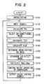
- FIG. 2 schematically shows control processing performed by the microcomputer of the air-conditioning ECU 5.
- the control routine of FIG. 2 starts, when the air flow switch 37c (or an AUTO switch) among the control switches 37 of the air-conditioning control panel 36 is turned on when an ignition switch of the vehicle engine 4 is turned on and power is supplied to the air-conditioning ECU 5.
- step S100 initialization of flags and timers and so on is carried out. Then, at step S110, detection signals from the sensors 32 and 33 and the sensor group 35, operation signals from the control switches 37, and vehicle running signals from the vehicle engine ECU 38 are input.
- a target outlet temperature (TAO) of an air-conditioning air to be blown into the passenger compartment is calculated.
- the target outlet temperature (TAO) is temperature needed to maintain the passenger compartment at a set temperature Tset set by the temperature setting switch 37a.
- TAO Kset ⁇ Tset - Kr ⁇ Tr - Kam ⁇ Tam - Ks ⁇ Ts + C
- an air-conditioning mode is selected to be one of a cold-storing mode, a cold-releasing mode, or a normal mode.
- the cold-storing switch 37b when the cold-storing switch 37b is turned on during running of the engine 4 (and the compressor 1), the cold-storing mode is selected, and when the cold-storing switch 37b is not turned on during running of the engine 4 (and the compressor 1), the normal mode is selected.
- the cold-releasing mode is selected.
- a target evaporator air outlet temperature TEO is calculated.
- the target evaporator air outlet temperature TEO is calculated on the basis of a first target evaporator air outlet temperature TEO1, a second target evaporator air outlet temperature TEO2, and a third target evaporator air outlet temperature TEO3, which will be discussed next.
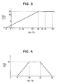
- FIG. 3 is a preset map stored in the ROM of the microcomputer.
- the first target evaporator air outlet temperature TEO1 is determined based on the map of FIG. 3 so that the TEO1 becomes higher as the TAO is higher.
- TEO1 f(TAO).
- TEO1 has an upper limit of 12°C, for example.
- the second target evaporator air outlet temperature TEO2 also is determined on the basis of a preset map, shown in FIG. 4, stored in the ROM of the microcomputer.
- the second target evaporator air outlet temperature TEO2 is determined in accordance with the outside air temperature Tam. As shown in FIG. 4, because the need for cooling and dehumidification diminishes in a medium temperature region of the outside air temperature Tam (e.g., 18°C - 25°C), the second target evaporator air outlet temperature TEO2 is set to be higher (e.g., 12°C), so that the operation rate of the compressor 1 is reduced and consumption power on the engine 4 is reduced.
- the second target evaporator air outlet temperature TEO2 is reduced in inverse proportion to rising of the outside air temperature Tam, so that cooling capacity for the passenger compartment can be secured. Further, when the outside air temperature Tam is lower than 18°C, to secure dehumidifying capacity for preventing fogging of the windows, the second target evaporator air outlet temperature TEO2 is reduced with decreasing of the outside air temperature Tam. And when the outside air temperature Tam becomes below 10°C, the second target evaporator air outlet temperature TEO2 becomes 0°C. Thus, TEO 2 can be expressed as f(Tam).
- the third target evaporator air outlet temperature TEO3 is set to a predetermined value below freezing point Tf (e.g., -2°C) when the cold-storing switch 37b is turned on.
- TEO MIN f ( TAO ) , f Tam
- the lower temperature is finally set as the target evaporator air outlet temperature TEO.
- the target evaporator air outlet temperature TEO is forcibly lowered to the predetermined value below freezing point Tf.
- a target air-blowing amount BLW blown by the blower 11 is calculated based on the above-mentioned TAO. That is, on the high-temperature side (maximum heating side) and the low-temperature side (maximum cooling side) of the above-mentioned TAO, the target air-blowing amount BLW is made large. On the other hand, in a medium temperature area of TAO, the target air-blowing amount BLW is made small.
- the rotation speed of the driving motor 13 of the blower 11 is controlled by an output of the air-conditioning ECU 5 so that the target air-blowing amount BLW is obtained.
- an inside/outside air mode is determined in correspondence with TAO.
- the inside/outside air mode is switched from an entire inside air mode to an inside/outside air mixing mode and then to an entire outside air mode as TAO rises from a low temperature side to a high temperature side.
- the position of an inside/outside air door (not shown) is controlled by an output of the air-conditioning ECU 5 so that an inside/outside air mode corresponding to the target air temperature TAO is obtained.
- an air outlet mode is determined in accordance with the calculated TAO.
- the air outlet mode is switched in a known fashion from a face mode to a bi-level mode and then to a foot mode as TAO rises from the low temperature side to the high temperature side.
- the positions of the air outlet mode doors 26, 28, 30 are controlled by an output of the air-conditioning ECU 5 through the electric driving device 31 so that an air outlet mode corresponding to the TAO is obtained.
- step S170 a target opening degree (target aperture) SW M of the air-mixing door 19 and a target opening degree (target aperture) SW B of the bypass door 17 are calculated, and rotation positions of the air-mixing door 19 and the bypass door 17 are determined.
- the step S170 will be discussed later in detail with reference to FIG. 5.
- the target evaporator air outlet temperature TEO and the actual evaporator air outlet temperature Te are compared, and on/off operation control of the compressor is performed. That is, when the detected evaporator air outlet temperature Te becomes lower than the target evaporator air outlet temperature TEO, the air-conditioning ECU 5 interrupts electrical current supplying to the electromagnetic clutch 2 and thereby stops the operation of the compressor 1. Conversely, when the evaporator air outlet temperature Te rises above the target evaporator air outlet temperature TEO, the air-conditioning ECU 5 supplies current to the electromagnetic clutch 2 and thereby operates the compressor 1. In the way, the evaporator air outlet temperature Te is kept at the target evaporator air outlet temperature TEO.
- step S190 vehicle engine control signals such as the signals of the above-mentioned stoppage permission or stoppage prohibition of the engine 4 and the signal of a restart request after stoppage of the engine 4 are outputted based on the air-conditioning conditions.
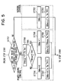
- FIG. 5 shows the details of step S170 in FIG. 2.
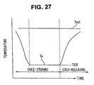
- the cold-storing mode is a state wherein the cold-storing switch 37b is turned on and the target evaporator air outlet temperature TEO is lowered to the predetermined value below freezing point Tf.
- the cold-releasing mode is a state wherein while the cold-storing switch 37b is turned on, the vehicle has halted for example at a traffic signal, a signal requesting stoppage of the engine 4 has been outputted from the vehicle engine ECU 38, and the engine 4 (and hence the compressor 1) has consequently stopped. That is, during the cold-releasing mode, the compressor 1 has stopped but air is cooled in the evaporator 9 by a cold-releasing action of stored cold in condensed water on the evaporator 9.
- step S1702 sets the target opening degree SW B of the bypass door 17 to zero and thereby operates the bypass door 17 to the position in which it fully closes the first bypass passage 16. Processing then proceeds to step S1703 and calculates the target opening degree SW M of the air-mixing door 19 using the following expression Exp. 3.
- SW M J Te ⁇ Tw ⁇ TAO
- SW M is calculated as a function of the evaporator air outlet temperature Te, the hot water temperature Tw of the heater core 20, and the target outlet temperature TAO. Therefore, a target opening degree SW M for obtaining the target outlet temperature TAO is calculated.
- the target opening degree SW M is calculated as a percentage. That is, the maximum cooling position in which the air passage of the heater core 20 is fully closed is set to 0%, and the maximum heating position in which the second bypass passage 21 is fully closed is set to 100%.
- the temperature control of the above-mentioned steps S1702 and S1703 is normal control. During the normal control, after the entire blown-air passes through the evaporator 9 and is cooled by the evaporator 9, the flow proportions of air passing through the heater core 20 and air passing through the second bypass passage 21 are adjusted by the opening degree of the air-mixing door 19 so that the temperature of air flowing into the passenger compartment approaches the target outlet temperature TAO.
- a third control mode of the present invention is constituted by the steps S1702 and S1703.
- step S1705 the maximum temperature TMmax of mixed air and the target outlet temperature TAO are compared.
- TM max is higher than the target outlet temperature TAO, because heating by means of the heater core 20 is unnecessary, processing proceeds to step S1706 and sets the target opening degree SW M of the air-mixing door 19 to 0 (%), and thereby the air-mixing door 19 is operated to the maximum cooling position (the position shown by the solid line in FIG. 1).
- a target opening degree SW B of the bypass door 17 is calculated based on the following expression Exp. 5.
- SW B H Te ⁇ T B ⁇ TAO
- SW B is calculated as a function of the evaporator air outlet temperature Te, the bypass air temperature TB of air passing through the first bypass passage 16, and the target outlet temperature TAO. Further, the bypass door 17 is operated to the position of a target opening degree SW B for obtaining the target outlet temperature TAO.
- the target opening degree SW B is calculated as a percentage. That is, the fully closed position of the first bypass passage 16 is set to 0% and the fully open position of the first bypass passage 16 is set to 100%.
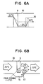
- FIGS. 6A and 6B are views illustrating the power-saving effect of the first preferred embodiment.
- FIG. 6A is a schematic view illustrating control of the temperature of air blown into the passenger compartment when a cold-storing mode is combined with an ordinary series air-mixing configuration. That is, in FIG. 6A, after the entire amount of air taken in at 25°C is cooled by the evaporator 9 to -2°C for cold-storing, air at 10°C is produced by the air being reheated by the heater core 20. Therefore, it is compared to a case wherein the evaporator air outlet temperature is controlled to 10°C by power-saving control from the start, as shown by the dashed line in FIG. 6A, it is necessary for the cooling capacity of the evaporator 9 to be increased. Therefore, the compressor operation rate arising from on/off control of the compressor 1 becomes higher, and there is a consequent increase in the compressor driving power load.
- FIG. 6B is a schematic view illustrating control of the temperature of air blown into the passenger compartment with the parallel air-mixing configuration of the first embodiment.
- air at 10°C blown into the passenger compartment is produced by mixing non-cooled air at 25°C passing through the first bypass passage 16 and cool air at -2°C passing through the evaporator 9.
- Tf -2°C
- the first control mode of the invention is constituted by the steps S1706 and S1707.
- step S1708 the target opening degree SW B of the bypass door 17 is set to 100 (%), and the bypass door 17 is operated to the fully-opening position at which it fully opens the first bypass passage 16.
- step S1709 a target opening degree SW M of the air-mixing door 19 is calculated based on the following expression Exp. 6.
- SW M G TMmax ⁇ Tw ⁇ TAO
- SW M is calculated as a function of the maximum temperature TMmax of the mixed air on the immediately downstream side of the evaporator 9, the hot water temperature Tw of the heater core 20 and the target outlet temperature TAO. Further, the air-mixing door 19 is operated to the position of the target opening degree SW M for obtaining the target outlet temperature TAO.
- the bypass door 17 is operated to fully open the first bypass passage 16 and to reduce the flow amount of air passing through the evaporator 9, so that the power-saving effect is also obtained.
- the second control mode of the invention is constituted by the above-mentioned steps S1708 and S1709.
- steps S1704 through S1709 described above is also performed when the system is determined to be in the cold-releasing mode at step S1701, i.e. when the vehicle is halted and the vehicle engine (and hence the compressor) is stopped and air is being cooled by cold-releasing of cold stored in the condensed water on the evaporator 9.
- the cold-releasing mode because the flow amount of air passing through the evaporator 9 is reduced by increasing air passing through the first bypass passage 16, it is possible to extend the time over which cold stored in the condensed water on the evaporator 9 is released, compared to the case shown in FIG. 6A.
- the cooling feeling obtained during vehicle engine stoppages at traffic signals and so on can be maintained well for a long time with the cold-storing amount in the condensed-water on the evaporator 9. Further, when the system is determined to be in the power-saving mode at step S1701, the temperature control of steps S1704 through S1709 described above is also carried out. In the power-saving mode also, power-saving is achieved by a reduction in the flow amount of air passing through the evaporator 9.
- the first embodiment can be modified in various ways.
- a cold-storing switch 37b for generating a cold-storing mode signal is provided as one of the control switches 37 on the air-conditioning control panel 36, and the cold-storing mode is set by turning on the cold-storing switch 37b.
- the invention is not limited to the control method, and the cold-storing mode can be set automatically on the basis of air-conditioning operation conditions.
- the cold-storing mode could be set automatically on the basis of variation in the target outlet temperature TAO.
- the target outlet temperature TAO is calculated to be a very low temperature such as -20°C or below at times such as during initial cool-down of the passenger compartment immediately after the start of cooling or in a case where the cooling load is high. Therefore, when the target outlet temperature TAO is extremely low, normal control may be carried out instead of the cold-storing mode, to obtain the maximum cooling capacity for the passenger compartment.
- the cold-storing mode may be automatically set.
- the cold-storing mode may be generally set when the engine 4 (specifically, the compressor 1) is running, and then normal control (the normal control mode) is set during running of the engine 4 (the compressor 1) only when it is determined that a condition for prohibiting the cold-storing mode is established.
- the target evaporator air outlet temperature TEO is set to a relatively low temperature to raise the dehumidifying (i.e. cooling) capacity of the evaporator 9, and the target outlet temperature TAO is increased to control the temperature inside the passenger compartment.
- the bypass door 17 may be fixed to the fully closed position, and control of the air temperature blown into the passenger compartment may be performed by adjusting the amount of air passing through the heater core 20 by using the air-mixing door 19.
- the target evaporator air outlet temperature TEO is lowered to a low temperature below freezing point such as -2°C to achieve an improvement in cold-storing effect
- the target evaporator air outlet temperature TEO may be lowered to a temperature lower than its minimum temperature at times of normal control (for example 3°C) but higher than 0°C (for example 1°C) to achieve an improvement in cold-storing effect.
- the first bypass passage 16 and the bypass door 17 are disposed on the lower side of the evaporator 9.
- the first bypass passage 16 and the bypass door 17 can alternatively be disposed on either or both of the right and left sides or on the upper side of the evaporator 9.
- the bypass door 17 can be disposed on the downstream air side of the evaporator 9, and can alternatively be disposed on the upstream air side of the evaporator 9.
- the following second preferred embodiment relates to a detecting unit for detecting the evaporator cooling degree.
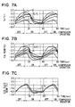
- Experimental studies carried out by the present inventors have shown that when water condensed on the evaporator 9 is made to freeze in order to store cold during the cold-storing mode, the formation of ice on the surface on the evaporator 9 tends for various reasons to be nonuniform. Consequently, on the air outlet side of the evaporator 9, because the flow of air is obstructed by the ice in places where there is ice, the air temperature is lower than that in places where there is no ice.
- FIGS. 7A - 7C are views of experimental data showing behavior of evaporator temperature with on/off operation of the compressor 1.
- the horizontal axis indicates on/off operation of the compressor 1, and time (sec) for performing the on/off operation of the compressor 1.
- a maximum detected temperature difference of 5.1°C arises among five different detection sites.
- a temperature sensor 32 is disposed in contact with a side plate 90 forming a side refrigerant passage of the evaporator 9, as shown in FIG. 8. Because the side plate 90 is made of a metal such as aluminum having a sufficient thermal conductivity, the evaporator refrigerant temperature can be detected effectively by the temperature sensor 32 through the wall of the side plate 90.
- FIG. 9 shows an example wherein the temperature sensor 32 is mounted in contact with a refrigerant inlet pipe 91 of the evaporator 9 to detect the evaporator refrigerant temperature.
- the temperature sensor 32 may alternatively be mounted on a refrigerant outlet pipe 92, or on a tank part 93 or 94, of the evaporator 9. In short, it is sufficient if the temperature sensor is mounted in a location where it can directly detect the evaporator refrigerant temperature.
- the following third preferred embodiment has the object of making the control described in the first preferred embodiment more specific and showing how the mixed air temperature TM between air having passed through the evaporator 9 and air having passed through the bypass passage 16 can be calculated accurately and how simultaneously an increase in the precision of control of the temperature of air blown into the passenger compartment can be achieved.
- the overall construction of the third preferred embodiment and the overall flow of control therein are the same as those of the first preferred embodiment shown in FIG. 1 and FIG. 2 and therefore will not be described again here.
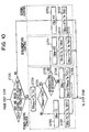
- FIG. 10 is a flow diagram showing a characteristic feature of the third preferred embodiment, and corresponds to FIG. 5 of the above-described first embodiment.
- the calculations of the target opening degree SW M of the air-mixing door 19 and the target opening degree SW B of the bypass door 17 carried out at step S170 in the third preferred embodiment will be described in detail based on the flow diagram shown in FIG. 10.
- the target opening degree SW M of the air-mixing door 19 is calculated using the following Exp. 7.
- SW M ( TAO - TM ) / Tw - TM where, TAO is the target outlet temperature of air blown into the passenger compartment, TM is temperature of mixture of air from the evaporator 9 and air from the bypass passage 16, and Tw is temperature of hot water flowing into the heater core 20.
- the target opening degree SW M of the air-mixing door 9 is calculated as a percentage. That is, at the maximum cooling position in which the air passage of the heater core 20 is fully closed, the target opening degree SW M of the air-mixing door 9 is set to 0%. Further, at the maximum heating position in which the second bypass passage 21 is fully closed, the target opening degree SW M of the air-mixing door 9 is set to 100%. For the calculation of the target opening degree SW M of the air-mixing door 19 using Exp. 7, it is necessary to calculate the mixed air temperature TM.
- a target opening degree SW B of the bypass door 17 is calculated using the following expression Exp. 8.
- SW B K ⁇ TM - Te ) / ( T B - Te where TM is temperature of mixture of air from evaporator 9 and air from bypass passage 16, Te is the evaporator air outlet temperature, TB is temperature (bypass air temperature) of air passing through the bypass passage 16, and K is constant determined by a shape of the air-conditioning case 10.
- the target opening degree SW B of the bypass door 17 is calculated as a percentage in which the fully closed position of the first bypass passage 16 is set to 0% and the fully open position of the first bypass passage 16 is set to 100%.
- the mixed air temperature TM between air from the evaporator 9 and air from the bypass passage 16 can be calculated using the following expression Exp. 9, which is derived from Exp. 8.
- TM Te + [ SW B ⁇ T B - Te ] / K
- Te the evaporator air outlet temperature
- TB the temperature of air passing through the bypass passage 16
- SW B is the target opening degree of the bypass door 17
- K is the constant determined by the shape of the air-conditioning case 10.
- K Ve + V B / V B
- FIG. 10 steps similar to those in FIG. 5 are indicated with the same step numbers.
- the cold-storing mode is a state wherein the cold-storing switch 37b is turned on and the target evaporator air outlet temperature TEO is lowered to the predetermined value below freezing point Tf.
- the cold-releasing mode is a state wherein, with the cold-storing switch 37b turned on, the vehicle is halted for example at a traffic signal, a signal requesting stoppage of the engine 4 has been outputted from the vehicle engine ECU 38, and the engine 4 (and hence the compressor 1) is consequently stopped. That is, during the cold-releasing mode, the compressor 1 is stopped but air is cooled in the evaporator 9 by a cold-releasing action of stored cold in condensed water on the evaporator 9.
- step S1702 sets the target opening degree SW B of the bypass door 17 to zero and thereby operates the bypass door 17 to the position in which it fully closes the first bypass passage 16. Processing then proceeds to step S1703 and calculates the target opening degree SW M of the air-mixing door 19 using the expression Exp. 7 given above.
- the target opening degree SW B of the bypass door 17 is zero during the normal control, the mixed air temperature TM between air from the evaporator 9 and air from the bypass passage 16 is equal to the evaporator air outlet temperature Te, and the target opening degree SW M of the air-mixing door 19 is calculated as a function of the evaporator air outlet temperature Te, the hot water temperature Tw of the heater core 20 and the target outlet temperature TAO using the following expression Exp. 11.
- SW M J Te ⁇ Tw ⁇ TAO
- the temperature control of the above-mentioned steps S1702 and S1703 is normal control, in which after the entire flow amount of blown air passes through and is cooled by the evaporator 9, the flow proportions of air passing through the heater core 20 and air passing through the second bypass passage 21 are adjusted with the opening degree of the air-mixing door 19 so that the temperature of air entering the passenger compartment approaches the target outlet temperature TAO.
- the third control mode of the present invention is constituted by the steps S1702 and S1703 described above.
- step S1704 calculates a maximum temperature TMmax of mixed air made up of air passing through the evaporator 9 and air passing through the first bypass passage 16, based on the temperature TB of bypass air (non-cooled air) passing through the first bypass passage 16 and the air temperature Te passing through the evaporator 9.
- TMmax F Te ⁇ T B
- step S1705 the maximum temperature TMmax of mixed air and the target outlet temperature TAO of air blown into the passenger compartment are compared.
- TMmax is higher than the target outlet temperature TAO, because reheating by means of the heater core 20 is unnecessary, processing proceeds to step S1706 and sets the target opening degree SW M of the air-mixing door 19 to 0 (%), and thereby fixes the air-mixing door 19 at its maximum cooling position (the position in which it is shown with solid lines in FIG. 1).
- a target opening degree SW B of the bypass door 17 is calculated based on the following expression Exp. 13.
- SW B H Te ⁇ T B ⁇ TAO
- SW B is calculated as a function of the evaporator air outlet temperature Te, the bypass air temperature TB of air passing through the first bypass passage 16, and the target outlet temperature TAO of air blown into the passenger compartment. Further, the bypass door 17 is operated to the position of a target opening degree SW B for obtaining the target outlet temperature TAO.
- the first control mode of the present invention is constituted by the above-mentioned steps S1706 and S1707.
- step S1705 when the target outlet temperature TAO is determined to be higher than the maximum temperature TMmax of mixed air between air from the evaporator 9 and air from the first bypass passage 16, heating operation due to the heater core 20 is necessary.
- processing firstly proceeds to step S1710 and it is determined whether or not dehumidifying control for preventing fogging of the windows or the like is necessary. Specifically, dehumidifying control is carried out when the air outlet mode is the defroster mode. Further, even when the air outlet mode is not the defroster mode, because it may be determined that dehumidification is necessary if conditions are such that fogging of the windows is liable to occur or the humidity is high, it is also determined that dehumidification is necessary when for example the outside air temperature Tam is below a predetermined temperature (for example 10°C).
- a predetermined temperature for example 10°C
- SW M is calculated as a function of the maximum temperature TMmax of the mixed air, the hot water temperature Tw of the heater core 20 and the target outlet temperature TAO of air blown into the passenger compartment. Further, the air-mixing door 19 is operated to the position of the target opening degree SW M for obtaining the target outlet temperature TAO.
- bypass door 17 is operated to fully open the first bypass passage 16 and to reduce the flow amount of air passing through the evaporator 9, so that the power-saving effect is also obtained.
- the second control mode of the present invention is constituted by the above-mentioned steps S1708 and S1709.
- step S1710 when it is determined at step S1710 that dehumidification is necessary, the following dehumidification control (S1711 through S1713) is carried out. That is, essentially to obtain a power-saving effect, it is necessary to fully open the bypass door 17 as in the second control mode (S1709, S1710) described above.
- the second control mode S1709, S1710
- air bypassing the evaporator 9 while passing through the first bypass passage 16, which is not dehumidified lowers the dehumidifying effect undesirably.
- the bypass door 17 is closed slightly (SW B is reduced) to increase the flow amount of air passing through the evaporator 9, so that power-saving and a dehumidifying effect can be obtained at the same time.
- the fourth control mode of the present invention is constituted by steps S1711 through S1713.
- a mixed air temperature TM of a mixture of air from the evaporator 9 and air from the bypass passage 16 is calculated using the above expression Exp. 9.
- the mixed air temperature TM can be calculated as a function of the evaporator air outlet temperature Te and the bypass air temperature T B according to the following expression Exp. 15, using the target opening degree SW B determined at step S1711.
- TM K Te ⁇ T B ⁇ SW B
- SW M L TM ⁇ T w ⁇ TAO
- step S1701 when the system is determined to be in the cold-releasing mode, the temperature control of steps S1704 through S1713 described above in FIG. 10 is carried out.
- the cold-releasing mode also, because the flow amount of air passing through the evaporator 9 is reduced and air passes through the first bypass passage 16, it is possible to extend the time over which cold stored in condensed water on the evaporator is released.
- step S1701 the system is determined to be in the power-saving mode
- the temperature control of steps S1704 through S1713 described above in FIG. 10 is carried out.
- the flow amount of air passing through the evaporator 9 is reduced, power-saving can be effectively achieved.
- the present invention is applied to an air-conditioning system mounted on a vehicle whose engine 4 is stopped at times when engine power is not required, such as when the vehicle is halted at a traffic signal.
- the invention is not limited to the vehicle and can be broadly applied to any vehicle air-conditioning system having the first bypass passage 16 through which air bypasses the evaporator 9, even if the vehicle air-conditioning system does not carry out air-conditioning during engine stoppages.
- the bypass air temperature sensor 33 consisting of a thermistor is provided in the first bypass passage 16 and the mixed air temperature TM is calculated using a bypass air temperature T B detected by the bypass air temperature sensor 33.
- the bypass air temperature sensor 33 it is possible to dispense with the bypass air temperature sensor 33.
- the outside air temperature Tam is used instead of the bypass air temperature T B during the outside air mode
- the inside air temperature Tr is used instead of the bypass air temperature T B during the inside air mode, to calculate the mixed air temperature TM in the same way as when the bypass air temperature T B is used.
- dehumidification is determined to be necessary when the air outlet mode is the defroster mode or when the outside air temperature Tam is below a predetermined temperature (for example 10°C), it may be determined that dehumidification of the passenger compartment is necessary if conditions are such that fogging of the windows is likely or the humidity inside the passenger compartment is high.
- a predetermined temperature for example 10°C
- the necessity or otherwise of dehumidification of the passenger compartment may be determined on the basis of whether either of these modes has been selected.
- a humidity sensor for detecting the humidity inside the passenger compartment may be provided, and dehumidification may be determined to be necessary when the passenger compartment humidity detected by the humidity sensor is above a predetermined level.
- a glass temperature sensor for detecting the temperature of the window glass may be provided, and dehumidification may be determined to be necessary when the temperature of the window glass is below a predetermined temperature. Because the window glass is more likely to fog up in the case of the inside air mode in which inside air is recirculated, than in the outside air mode in which outside air is introduced, it may be determined that dehumidification of the passenger compartment is necessary when air-conditioning is being carried out in the inside air mode.
- dehumidification of the passenger compartment is determined to be necessary when the outside air temperature Tam is below a predetermined temperature (for example 10°C) and furthermore the passenger compartment humidity is above a predetermined level.
- bypass door opening degree SW B may alternatively be variably controlled in correspondence with the degree of necessity of dehumidification (the degree of humidity or the like).
- bypass door opening degree SW B when the humidity is high, the necessity of dehumidification is high, and the bypass door opening degree SW B may be made smaller so that more air passes through the evaporator 9 and priority is given to dehumidification rather than power-saving. And when the humidity is not so high, the bypass door opening degree SW B may be made larger so that more air passes through the first bypass passage 16 and priority is given to power-saving rather than dehumidification.
- the mixed air temperature TM of a mixture of air from the evaporator 9 and air from the first bypass passage 16 is used to calculate the target opening degree SW M of the air-mixing door 19.
- a target hot water flow may be calculated using the mixed air temperature TM.
- the target temperature (TEO) of evaporator temperature is lowered to a temperature below freezing point such as -3°C or -4°C to cause freezing of water condensed on the evaporator 9, compared to times of normal control when the target temperature (TEO) is about +3°C or +4°C, the temperature difference between the evaporator temperature and the air temperature sucked into the evaporator 9 is greater and more dehumidification is performed in the evaporator 9. Therefore, in the cold-storing mode, the humidity inside the passenger compartment is amply reduced.
- TEO target temperature
- the passenger in the passenger compartment undergo the affect not only of a temperature rise but also of a sudden rise in the passenger compartment humidity, and consequently in the sense of humidity (mugginess due to humidity) aspect the cooling feeling deteriorates markedly. Further, because of the deterioration in the cooling feeling caused by a sense of humidity, the time for which the cold-releasing mode is continued must be shortened.
- the following fourth preferred embodiment has an object of suppressing deterioration of the cooling feeling caused by the humidity in the cold-releasing mode during an engine stoppage (compressor stoppage).
- the fourth preferred embodiment also has an another object of extending the time for which it is possible to maintain a good cooling feeling in the cold-releasing mode during an engine stoppage (compressor stoppage).
- the overall construction of the fourth preferred embodiment is the same as that of the first preferred embodiment shown in FIG. 1 and therefore will not be described here.
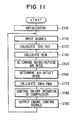
- the overall flow of control in the fourth preferred embodiment, as shown in FIG. 11, also is substantially similar to that of the first preferred embodiment shown in FIG. 2, with step S121 of FIG. 11 performing a role equivalent to that of steps S120 and S130 in FIG. 2.
- FIG. 12 shows details of the step S121 of FIG. 11.
- a target outlet temperature TAO of conditioned air to be blown into the passenger compartment and a target evaporator air outlet temperature TEO are calculated.
- FIG. 12 shows the details of the step S121 in FIG. 11.
- a reference target outlet temperature TAO A is calculated.
- the reference target outlet temperature TAO A is an air temperature necessary to maintain the passenger compartment at the set temperature Tset of the temperature setting switch 37a, and can be calculated on the basis of the heat load conditions of the passenger compartment using the foregoing expression Exp. 1.
- step S1202 it is determined whether or not conditions allow the execution of the cold-storing mode during engine operation (during vehicle travel). That is, it is determined whether or not the cold-storing mode is possible, at step S1202. Specifically, the determination can be carried out on the basis of the above-mentioned reference target outlet temperature TAO A . That is, the reference target outlet temperature TAO A is in a low region such as below -20°C at times such as during cool-down of the passenger compartment immediately after the start of cooling, when the passenger compartment temperature must be lowered rapidly toward the set temperature Tset, or when the cooling load is high like when the outside air temperature is high and furthermore there are many passengers in the vehicle. In this case, when TAO A is in a low region below the predetermined value, to give priority to cooling performance, the execution of the cold-storing mode is prohibited and the normal mode is performed.
- step S1203 calculates the target evaporator air outlet temperature TEO A in the normal control mode.
- the target evaporator air outlet temperature TEO A during the normal mode is calculated on the basis of a first target evaporator air outlet temperature TEO A1 and a second target evaporator air outlet temperature TEO A2 , which will be discussed next.
- the first target evaporator air outlet temperature TEO A1 is determined on the basis of the map shown in FIG. 13 (the same characteristic as that of FIG. 3). Then, the second target evaporator air outlet temperature TEO A2 is determined on the basis of the map shown in FIG. 14 (the same characteristic as that of FIG. 4).
- the target evaporator air outlet temperature TEO A is finally determined based on the first and second target evaporator air outlet temperatures TEO A1 , TEO A2 .
- the lower temperature is finally set as the target evaporator air outlet temperature TEO A .
- step S1203 sets the target outlet temperature TAO of air blown into the passenger compartment to the reference target outlet temperature TAO A .
- the reference target outlet temperature TAO A is higher than a predetermined value (for example, -20°C) at step S1202, it is inferred that the cooling load is steady-state and it is determined that the cold-storing mode can be executed. Accordingly, processing proceeds to step S1205 and determines whether or not the vehicle engine 4 is running. The determination can be performed on the basis of whether or not the vehicle speed signal or the engine speed signal inputted from the vehicle engine ECU 38 is above a predetermined value.
- step S1206 determines a target evaporator air outlet temperature TEO B for the cold storing mode.
- the target evaporator air outlet temperature TEO B during the cold storing mode is a predetermined temperature below freezing point Tf (for example, -2°C to -1°C). Therefore, the condensed water on the evaporator 9 can be cooled to the temperature below freezing point T f and thus frozen, whereby the cold-storing mode is performed.
- the target outlet temperature TAO is set to the reference target outlet temperature TAO A at step S1204.
- step S1205 when the engine has been stopped, the system is in the cold-releasing mode, and processing proceeds to step S1207.
- step S1207 humidity correction control for the cold-releasing mode is performed. That is, the target outlet temperature TAO is set to a cold-releasing TAO B .
- the cold-releasing TAO B is calculated using the following expression Exp. 17.
- TAO B TAO A - f ( Te ) + g f ⁇ Te
- Te is the actual evaporator air outlet temperature detected by the evaporator air outlet temperature sensor 32
- f(Te) in Exp. 17 is a correction component dependent on the passenger compartment humidity (relative humidity). That is, because there is a correlation between the passenger compartment humidity and the evaporator air outlet temperature Te, the passenger compartment humidity can be estimated based on Te. Specifically, because the passenger compartment humidity rises with Te, the correction component f(T e ) dependent on the passenger compartment humidity can be expressed by a relationship wherein it increases as Te rises, as shown in FIG. 15.
- g(f'(Te)) in Exp. 17 is a correction component dependent on the rate of change (rate of increase) of the passenger compartment humidity (relative humidity), and can be set for example as shown in FIG. 16.
- the f'(Te) on the horizontal axis of FIG. 16 is the rate of change of the passenger compartment humidity estimated by differentiation with respect to time of the evaporator air outlet temperature Te, and the correction component g(f'(Te)) dependent on the rate of change of the passenger compartment humidity increases in correspondence with increasing of the term f'(Te).
- step S1207 constitutes correcting means during the cold-releasing mode.
- processing proceeds through steps S140, S150 and S160 to step S170, calculates the target opening degree SW M of the air-mixing door 19 and the target opening degree SW B of the bypass door 17, and implements these opening degrees of the air-mixing door 19 and the bypass door 17.
- the target opening degree SW M of the air-mixing door 19 is expressed as a percentage in which the maximum cooling position of the air-mixing door 19 (the position in which it is shown with solid lines in FIG. 1) is set to 0% and the maximum heating position of the air-mixing door 19 (the position in which it is shown with dashed lines in FIG. 1) is set to 100%.
- the target opening degree SW B is expressed as a percentage in which the fully closed position of the first bypass passage 16 is set to 0% and the fully open position of the first bypass passage 16 is set to 100%.
- the calculation of the target opening degree SW M and the target opening degree SW B is carried out differently for each of the normal mode, the cold-storing mode and the cold-releasing mode.
- the target opening degree SW M can be determined based on the target outlet temperature TAO, the evaporator air outlet temperature Te, and the hot water temperature Tw of the heater core 20.
- the calculation of the target opening degree SW M of the air-mixing door 19 in the normal mode is the same as the above-described first embodiment during the normal mode.
- the temperature of air blown into the passenger compartment is adjusted by opening degree adjustment of the air-mixing door 19 (that is, adjustment of the amount of heating contributed by the heater core 20).
- the target opening degree SW M of the air-mixing door 19 is determined based on the temperature of the mixture between the air from the first bypass passage 16 and the air from the evaporator 9, the hot water temperature T w of the heater core 20, and the target outlet temperature TAO.
- the target outlet temperature TAO B of air blown into the passenger compartment is corrected to the low-temperature side with respect to the reference target outlet temperature TAO A on the basis of rising of the humidity in the passenger compartment as shown by the upper part of FIG. 17 using the correction component f(Te) due to the passenger compartment humidity and the correction component g(f'(Te)) due to the rate of change of the passenger compartment humidity (relative humidity).
- the target opening degree SW B of the bypass door 17 and the target opening degree SW M of the air-mixing door 19 are, specifically, determined as shown in the lower part of FIG. 17.
- the method by which SW B and SW M are determined for the cold-releasing mode will now be described in detail.
- the temperature of air blown into the passenger compartment may be lower than TAO B merely as a result of the non-cooled air from the first bypass passage 16 mixing with the air (cool air) having been passed through the evaporator 9.
- the target opening degree SW M of the air-mixing door 19 is set to a predetermined opening degree and the temperature of air blown into the passenger compartment is controlled to TAO B using reheating effected by the heater core 20.
- the target outlet temperature TAO B during the cold-releasing mode is corrected to the low-temperature side with respect to the reference target outlet temperature TAO A using both the correction component f(Te) dependent on the passenger compartment humidity and the correction component g(f'(Te)) dependent on the rate of change of the passenger compartment humidity. Therefore, with respect to rising of the evaporator air outlet temperature Te, it is possible to raise up for the perception level at which discomfort due to humidity is felt to the temperature level Te3 in the upper part of FIG. 17. In other words, after the start of the cold-releasing mode, the time at which the passenger feels discomfort due to humidity is the time t3, and the cooling feeling provided by the cold-releasing mode can be kept good until the time t3 elapses.
- the passenger feels discomfort due to a sense of humidity at the temperature level Te1 in the upper part of FIG. 17 with respect to the evaporator air outlet temperature Te, because the temperature of air blown into the passenger compartment becomes a somewhat high temperature not allowing for a sense of humidity. That is, the perception level at which discomfort due to a sense of humidity is felt becomes the temperature Te1 lower than the temperature level Te3, with respect to the evaporator air outlet temperature Te. As a result, the time for which the cooling feeling provided by the cold-releasing mode can be kept good becomes the short time t1.
- the perception level at which discomfort due to a sense of humidity is felt by the passenger becomes the temperature Te2 in the upper part of FIG. 17.
- the time for which the cooling feeling provided by the cold-releasing mode can be kept suitably becomes the time t2 between the above-mentioned times t1 and t3.
- step S170 of FIG. 11 After the step S170, at step S180 in FIG. 11, the target evaporator air outlet temperature TEO (TEO A or TEO B ) is compared with the actual evaporator air outlet temperature Te, and on/off control of the compressor 1 is carried out. That is, when the evaporator air outlet temperature Te is lowered below the target evaporator air outlet temperature TEO, the air-conditioning ECU 5 stops the compressor 1 by cutting off current to the electromagnetic clutch 2. Conversely, when the evaporator air outlet temperature Te rises above the target evaporator air outlet temperature TEO, the air-conditioning ECU 5 supplies current to the electromagnetic clutch 2 and thereby restarts the compressor 1.
- TEO target evaporator air outlet temperature
- the evaporator air outlet temperature Te is kept at the target evaporator air outlet temperature TEO.
- the target evaporator air outlet temperature TEO is lowered to TEO B (the predetermined value below freezing point Tf) to cause water condensing on the evaporator 9 to freeze, so that the amount of cold stored in the condensed water on the evaporator 9 is increased.
- Step S180 Processing then proceeds to step S180, and outputs engine control signals of the above-mentioned stoppage permission or stoppage prohibition of the engine 4 and of a restart request after stoppage of the engine 4 based on air-conditioning side conditions.
- the fourth preferred embodiment can be modified in various ways. For example, in the fourth embodiment described above, whether or not to execute the cold-storing mode is determined at step S1202 in FIG. 12 based on the target outlet temperature TAO ; however, alternatively, a cold-storing switch for generating a cold-storing mode signal may be provided as one of the control switches 37 of the air-conditioning control panel 36, so that the cold-storing mode is set by turning on the cold-storing switch. In the case, execution of the cold-storing mode can be decided based on the position of the cold-storing switch.
- the cold-storing mode may be generally set at all times when the engine 4 (specifically, the compressor 1) is operated, and then normal control (the normal control mode) is set during the operation of the engine 4 (the compressor 1) only when it has been determined that a condition for prohibiting the cold-storing mode is determined.
- the target evaporator air outlet temperature TEO can be set to a relatively low temperature to raise the dehumidifying (i.e. cooling) capacity of the evaporator 9, and the target outlet temperature TAO can be raised to control the temperature inside the passenger compartment.
- the bypass door 17 may be fixed in the fully closed position and control of the air temperature can be performed by the amount of reheating effected by the heater core 20 being adjusted by the air-mixing door 19, in the same way as the normal control (steps S1702, S1703).
- the target evaporator air outlet temperature TEO is lowered to a low temperature below freezing point such as -2°C to achieve an improvement in cold-storing effect.
- the target evaporator air outlet temperature TEO may be lowered to a temperature lower than its minimum temperature in the normal control (for example 3°C) but higher than 0°C (for example 1°C) to achieve an improvement in cold-storing effect.
- bypass door 17 does not have to be disposed on the downstream air side of the evaporator 9 and can alternatively be disposed on its upstream air side.
- the above-described fourth embodiment can also be applied to a vehicle air-conditioning system wherein the first bypass passage 16 and the bypass door 17 are dispensed with and only reheat amount adjusting means (e.g., air-mixing door 19 or a hot water valve) for adjusting the reheating amount effected by the heater core 20 is provided for adjusting the temperature of air blown into the passenger compartment.
- reheat amount adjusting means e.g., air-mixing door 19 or a hot water valve
- FIG. 18 is a schematic view of the construction of a vehicle air-conditioning system according to a fifth preferred embodiment of the present invention
- FIG. 19 is a sectional view showing an air-conditioning unit 15 on the downstream air side of the blower 11 in the ventilation system of the air-conditioning system. Parts the same as parts in FIG. 1 have been given the same reference numerals as in FIG. 1 and will not be described again here.
- the air-conditioning unit 15 is normally mounted behind a dash board at the front of the passenger compartment, in a central position in the width direction of the vehicle. In the case, the air-conditioning unit 15 is disposed as shown in FIG. 19 with respect to the front-rear direction of the vehicle and the vertical direction (up-down direction), and the blower 11 is disposed to be shifted to the front passenger seat side with respect to the air-conditioning unit 15.
- An air inlet 10a is formed at a most front of the air-conditioning case 10, and air blown by the blower fan 12 flows through the air inlet 10a into an inside space of the air-conditioning case 10, upstream of an evaporator 9.
- the evaporator 9 is disposed so as to extend in the vertical direction, and the first bypass passage 16 through which air bypasses the evaporator 9 is formed below the evaporator 9.
- a bypass door (parallel bypass door) 17 for adjusting the opening degree of the first bypass passage 16 is disposed on the upstream air side of the evaporator 9, at the lower side thereof .
- the bypass door 17 has a rotatable shaft 17a at a lower side of the front face of the evaporator 9 and is a plate-like door rotated around the shaft 17a.
- an operating position in which the bypass door 17 is rotated to the broken lines in FIGS. 18 and 19 is a position in which it fully opens the first bypass passage 16.
- the bypass door 17 also closes a part of the air passage through the evaporator 9 (the lower side area A) in a maximum extent, and thereby increases the flow resistance of the lower side area A.
- a predetermined small gap "B" is formed between the bypass door 17 and the surface of the heat-exchanging core part of the evaporator 9.
- the small gap "B” is for example in a range of 2 - 6mm, and more specifically about 5mm is preferable.
- an air-mixing door (series bypass door) 19 is disposed on the downstream air side of the evaporator 9.
- the hot water type heater core (heat exchanger for heating) 20 for heating air with hot water (cooling water) from the vehicle engine 4 as a heat source is disposed on the downstream air side of the air-mixing door 19.
- a second bypass passage 21 is formed to one side of (above) the hot water type heater core 20. The second bypass passage 21 is for allowing air to bypass the hot water type heater core 20.
- the air-mixing door 19 is a plate-like door rotatable around a pivot shaft 19a, and adjusts the flow proportions of air passing through the hot water type heater core 20 and air passing through the second bypass passage 21.
- the temperature of air blown into the passenger compartment can be adjusted.
- a warm air passage 23 curving upward from the lower side of the heater core 20 is formed on the downstream air side of the heater core 20, and warm air from the warm air passage 23 and cool air from the second bypass passage 21 can be mixed in an air-mixing part 24 to obtain conditioned air having a desired temperature.
- an air outlet mode switching part is provided on the downstream air side of the air-mixing part 24. That is, a defroster opening 25 is formed in the upper surface of the air-conditioning case 10, and air is blown from the defroster opening 25 through a defroster duct (not shown) toward the inner side of the front windshield of the vehicle.
- the defroster opening 25 is opened and closed by a plate-like defroster door 26 rotatable around a pivot shaft 26a.
- a face opening 27 is formed on a vehicle rear side of the defroster opening 25 in the upper surface of the air-conditioning case 10, and the face opening 27 directs air through a face duct (not shown) toward the upper body of a passenger in the passenger compartment.
- the face opening 27 is opened and closed by a plate-like face door 28 rotatable around a pivot shaft 28a.
- a foot opening 29 is formed below the face opening 27 in the air-conditioning case 10, and the foot opening 29 directs air through a foot duct (not shown) toward the feet area of the passenger in the passenger compartment.
- the foot opening 29 is opened and closed by a plate-like foot door 30 rotatable around a pivot shaft 30a.
- the shafts 26a, 28a and 30a of these air outlet mode doors 26, 28, 30 are connected to a common link mechanism (not shown), and are driven via the link mechanism by an electric driving device 31 consisting of a servo motor.
- FIGS. 18 and 19 show a normal state wherein the bypass door 17 closes the first bypass passage 16
- FIG. 20 shows an evaporator bypass state wherein the bypass door 17 opens the first bypass passage 16 and closes the lower side of the air passage through which air passes through the evaporator 9.
- the normal state shown in FIGS. 18 and 19 (the evaporator-bypass closed state) is set. Further, at times other than during cool-down or when the cooling load is high, that is, in the normal cooling load state, in preparation for the next engine stoppage, it is necessary to set a cold-storing mode for increasing the amount of cold stored in water condensed on the evaporator 9.
- the evaporator bypass state shown in FIG. 20 is a state of the cold-storing mode.
- the evaporator bypass state of FIG. 20 may be used not only for the cold-storing mode but also for a power-saving mode for the intermediate seasons of spring and fall, and can also be used for a cold-releasing mode for times of temporary engine stoppage for example when the vehicle is halted at a traffic signal.
- the normal state shown in FIGS. 18 and 19 (the evaporator-bypass closed state) and the evaporator bypass state can be switched by the bypass door 17. Opening and closing operations of the bypass door 17 can be determined for example on the basis of a target outlet temperature TAO of conditioned air blown into the passenger compartment.
- the target outlet temperature TAO of air blown into the passenger compartment is calculated to be a very low temperature, during the aforementioned cool-down period or when the cooling load is high when the target outlet temperature TAO is in an extremely low temperature.
- the bypass door 17 is operated to the normal state shown in FIGS. 18 and 19. Then, when the target outlet temperature TAO is risen to a predetermined level, it is determined that a normal cooling load state has been reached and the bypass door 17 is switched from the normal state shown in FIGS. 18 and 19 to the evaporator bypass state shown in FIG. 20.
- a cold-storing mode switch may be provided as one of the control switches 37 of the air-conditioning control panel 36, and the bypass door 17 may be operated to the evaporator bypass state of FIG. 20 when the cold-storing mode switch is turned on by a passenger.
- the air-mixing door 19 opens the air passage toward the heater core 20 and reduces the opening degree of the second bypass passage 21.
- the flow proportions of cool air from the second bypass passage 21 and warm air from the heater core 20 can be adjusted so that the air temperature blown into the passenger compartment is controlled.
- the bypass door 17 is switched to the evaporator bypass state shown in FIG. 20.
- the bypass door 17 opens the first bypass passage 16 and maximally closes the lower side area "A" of the air passage of the heat-exchanging core part of the evaporator 9.
- the operating position (opening degree) of the bypass door 17 can be determined on the basis of the temperature T B of the non-cooled air passing through the first bypass passage 16, the evaporator air outlet temperature Te and the target outlet temperature TAO of air blown into the passenger compartment.
- bypass door 17 closes a part of the air passage of the heat-exchanging core part of the evaporator 9, there is almost no heat-exchange between refrigerant and air in the closed part of the evaporator 9, and condensed water can be forcibly made to frost (freeze).
- the target evaporator air outlet temperature TEO of the evaporator 9 is normally set in correspondence with the target outlet temperature TAO to rise as the TAO rises, or in correspondence with the outside air temperature Tam to be highest in an intermediate temperature region of spring and fall or to be low in a low-temperature region and a high-temperature region of the outside air temperature Tam.
- the target evaporator air outlet temperature TEO is lowered to a low temperature below freezing point of for example -2°C to forcibly freeze condensed water on the evaporator 9 and thereby increase the amount of cold stored there.
- the evaporator 9 is disposed so that it extends in the vertical direction (vehicle up-down direction), water condensed on the evaporator 9 collects under its own weight in the lower side of the heat-exchanging core part of the evaporator 9. Consequently, by closing the lower side part of the air passage of the heat-exchanging core part of the evaporator 9 with the bypass door 17, it is possible to increase the amount of cold stored by forcibly freezing condensed water collecting in the lower side of the heat-exchanging core part of the evaporator 9.
- bypass door 17 contacts the surface of the heat-exchanging core part of the evaporator 9 when the bypass door 17 is operated to the position shown in FIG. 20 in which the bypass door 17 fully opens the bypass passage 16, there would be a risk of the bypass door 17 freezing integrally to the surface of the heat-exchanging core part and the bypass door 17 consequently becoming inoperable.
- a predetermined small gap "B" in a range of 2 - 6mm is formed between the bypass door 17 and the heat-exchanging core part of the evaporator 9. Therefore, even when the lower side part "A" of the heat-exchanging core part of the evaporator 9 is frozen, the bypass door 17 does not freeze to the surface of the heat-exchanging core part of the evaporator 9. Therefore, immobility of the bypass door 17 due to freezing is prevented.
- the evaporator 9 is the largest in size of the compartments mounted inside the air-conditioning case 10. Consequently, due to restrictions on mounting space within the vehicle, it may in practice be difficult to design the first bypass passage 16 having a sufficient cross-sectional area around the evaporator 9. It is thus beneficial in the connection that in the fifth preferred embodiment, when the first bypass passage 16 is opened by the bypass door 17, the lower side part of the air passage of the heat-exchanging core part of the evaporator 9 is closed by the bypass door 17, and the flow resistance of the passage through the evaporator 9 is increased. Thus, the bypass flow amount (i.e., flow amount of non-cooled air) passing through the first bypass passage 16 increases.
- bypass flow amount non-cooled air flow amount
- cool air flow amount from the evaporator 9
- FIGS. 21 and 22 show experimental results obtained by the inventors of the present invention.
- the vertical axis shows the overall air flow amount blown by the centrifugal blower fan 12 and the proportion (%) of the overall air flow amount constituted by the bypass flow amount (i.e., bypass air flow amount ratio %)
- the horizontal axis shows the height (i.e., closed height) to which the air passage of the heat-exchanging core part of the evaporator 9 is blocked by the bypass door 17.
- an entire height of the heat-exchanging core part of the evaporator 9 used in the experiment is 235mm
- the width (left-right direction) of the heat-exchanging core part is 253mm
- the passage area of the heat-exchanging core part is 59455 mm 2 .
- the small gap "B" between the bypass door 17 and the surface of the heat-exchanging core part of the evaporator 9 is 5mm.
- the passage height of the first bypass passage 16 is 60mm, the width of the first bypass passage 16 is 233mm, and therefore the cross-sectional area of the first bypass passage 16 is 13980mm 2 .
- the bypass air flow amount ratio relative to the overall air flow amount can be increased by increasing the closed height to which the air passage of the heat-exchanging core part of the evaporator 9 is blocked by the bypass door 17, and the bypass air flow amount ratio can be increased to over 40% when the closed height is set to 100mm or more.
- FIG. 22 is a table of experimental results showing the relationship between the closed height of evaporator 9, the bypass air flow amount ratio relative to the overall flow amount, a decreased ratio in overall flow amount, and temperature of mixed air on a downstream air side of evaporator 9.
- the bypass air flow amount ratio can be increased to 41% and the mixed air temperature downstream of the evaporator 9 can be controlled to 10.3°C.
- the mixed air temperature downstream of the evaporator 9 is the mixed air temperature in a case where the evaporator air outlet temperature Te is 0°C and the bypass air temperature TB is 25°C.
- the decreased ratio in overall flow amount is 4% and thus has been kept to a relatively small value. Thus, the decreased ratio in overall flow amount does not constitute a problem.
- the compressor 1 When the vehicle engine 4 is stopped during a temporary stop of the vehicle, for example at a traffic signal, the compressor 1 also inevitably stops, and the cooling action of the evaporator 9 due to the latent heat of evaporation of the refrigerant in the refrigerant cycle R is stopped.
- the cold stored in the condensed water on the evaporator 9 (latent heat of melting of water and sensible heat of water) can be utilized to obtain a cooling action of the evaporator 9 after the engine 4 stops.
- the time for which vehicles temporarily stop at traffic signals and the like is normally about one minute, and if the time is the short it is possible, utilizing cold stored in water condensed on the evaporator 9, for cooling to continue at a level such that there is no deterioration in cooling feeling.
- the vehicle air-conditioning system can set a cold-releasing mode during the vehicle halt.
- control of the air temperature blown into the passenger compartment in the cold-releasing mode can be performed by adjusting the operating position (opening degree) of the bypass door 17 while the air-mixing door 19 is fixed in its maximum cooling position.
- the following sixth preferred embodiment of the present invention addresses the point and reduces the temperature differences in air blown from the evaporator 9 during the cold-releasing mode.
- the bypass door 17 is operated to a position in which it opens the lower side area A of the air passage of the evaporator 9 to a predetermined opening degree from the start of the cold-releasing mode.
- FIG. 23E shows elapsed operating time of the air-conditioning system.
- the time, at which the engine 4 is stopped and the cold-releasing mode is started after the cold-storing mode is executed during operation of the vehicle engine 4 is set to zero
- the elapsed time of the cold-releasing mode is shown as time on the plus side
- the elapsed time of the cold-storing mode is shown as time on the minus side.
- FIG. 23A shows the cold-storing mode executed during operation of the vehicle engine 4
- FIGS. 23B, 23C, 23D show the cold-releasing mode when the opening degree of the first bypass passage 16 is reduced by the bypass door 17 in this order of FIGS. 23B, 23C, 23D along the elapses time increase of the cold-releasing mode.
- the bypass door 17 is operated to a position in which it opens the lower side area A of the air passage of the evaporator 9 by a predetermined angle ⁇ 1, as shown in FIGS. 23B, 23E.
- the opening degree of the first bypass passage 16 is decreased by the bypass door 17, and the amount of air passing through the first bypass passage 16 is decreased. Therefore, the air temperature blown into the passenger compartment is decreased.
- the operating position of the air-mixing door 19 is temporarily moved by a predetermined angle ⁇ 2 toward its maximum heating position side (i.e., hot side in FIG. 23E).
- the air-mixing door 19 is gradually moved back toward its maximum cooling position side (i.e., cool side in FIG. 23E) to maintain the air temperature (Tout) blown into the passenger compartment at the target outlet temperature TAO.
- the bypass door 17 is operated to the position in which it opens the lower side area A of the air passage of the evaporator 9 by the predetermined angle ⁇ 1 from the start of the cold-releasing mode, a certain flow amount of air can be introduced into the lower side area A also. Consequently, from the start of the cold-releasing mode, not only ice in the upper side of the air passage of the evaporator 9 but also ice in the lower side area A can be melted. Thus, it is possible to markedly reduce the temperature differences (make even the temperature distribution) of the air temperature from the evaporator 9 in the vertical direction. As a result, the evaporator air outlet temperature Te can be accurately detected with a single temperature sensor 32 mounted directly downstream the evaporator 9.
- the arrangement position of the temperature sensor 32 should be a position immediately behind the air outlet of the evaporator 9 and slightly above the bypass door 17 in a substantially central position in the vertical direction of the heat-exchanging core part of the evaporator 9.
- the evaporator air outlet temperature shown by graph “a” pertains to the sixth preferred embodiment
- the evaporator air outlet temperature shown by graph “b” pertains to a comparison example of an ordinary air-conditioning system (shown in FIG. 6A) not having the first bypass passage 16 or the bypass door 17.
- the comparison example because all of air blown from the blower 11 passes through the evaporator 9, the flow amount of air passing through the evaporator 9 is large. Consequently, the melting rate of the ice is high and the rate of increase of the evaporator air outlet temperature Te is rapid as shown by graph "b" in FIG. 23E.
- the bypass door 17 opens the first bypass passage 16 in the cold-releasing mode, so that the amount of air flowing through the evaporator 9 is decreased, the melting of ice on the evaporator 9 is thereby retarded and the rate of increase of the evaporator air outlet temperature Te can thus be reduced as shown by graph "a" in FIG. 23E.
- graph "a" in FIG. 23E it is possible to extend the time taken for the evaporator air outlet temperature Te to reach the above-mentioned air temperature Tout blown into the passenger compartment to 60 seconds from the start of the cold-releasing mode, as shown by the arrow "I" in FIG. 23E.
- the limit evaporator air outlet temperature Teo at which passengers of the passenger compartment feel uncomfortable can be made 1°C higher than in the case of the comparison example, as shown by the arrow "II" in FIG. 23E.
- the time for which the cold-releasing mode can be continued can be further extended by about four seconds.
- the amount of water held in the evaporator 9 (the amount of condensed water) is 100g
- the length of the bypass door 17 is 90mm
- the air amount flowing into the air-conditioning case 10 is 200m 3 /h.
- the initial evaporator passage opening degree of the bypass door 17 i.e., the evaporator passage opening degree at the start of the cold-releasing mode) is 1/4, when the state of FIG. 23D is taken as fully open.
- FIG. 24 shows experimental data showing the relationship between the evaporator passage opening degree of the bypass door 17 in the cold-releasing mode, the time (i.e., cold-releasing time in FIG. 24) for which the cold-releasing mode can be continued, and variation in the evaporator air outlet temperature Te.
- the experimental conditions are the same as those for FIGS. 23A-23E.
- the horizontal axis of FIG. 24 shows initial evaporator passage opening degree (the evaporator passage opening degree at the start of the cold-releasing mode) due to the bypass door 17, and the vertical axis shows time for which the cold-releasing mode can be continued and the variation in the evaporator air outlet temperature Te.
- the time for which the cold-releasing mode can be continued is the time taken for the evaporator air outlet temperature Te to rise to the limit evaporator air outlet temperature Teo explained above with reference to FIGS. 23A-23E.
- the variation in the evaporator air outlet temperature Te is the difference between the maximum and minimum values of the evaporator air outlet temperature Te.
- the possible cold-releasing mode duration can be kept at the same level as when the initial evaporator passage opening degree of the bypass door is 0/4 (fully closing the lower side of the evaporator 9).
- FIG. 25B shows experimental data showing a relationship between actual value (Te) of the evaporator air outlet temperature detected by the temperature sensor 32 disposed at different positions 32a, 32b, 32c as shown in FIG. 25A, and mean value (mean temperature) of the evaporator air outlet temperature.
- the experimental conditions are the same as those for FIG. 23E. That is, the evaporator passage opening degree due to the bypass door 17 corresponds to the fully close position of the lower side of the evaporator 9 shown in FIG. 23A during the cold-storing mode, and is varied between the initial evaporator passage opening degree of 1/4 and fully open opening degree of 4/4 during the cold-releasing mode.
- the arrangement position 32a is at an upper side
- the arrangement position 32b is at a vertically middle position
- the arrangement position 32c is at a lower side, relative to the heat-exchanging core part of the evaporator 9 within the air-conditioning case 10.
- the arrangement position 32b at the vertically middle position of the heat-exchanging core part of the evaporator 9 is positioned slightly above the bypass door 17, as mentioned before.
- step S1911 it is determined whether or not dehumidification of air within the passenger compartment is necessary. Specifically, when a passenger operates an air outlet mode switch 37c on the air-conditioning control panel 36 and the defroster mode is set (i.e. when the defroster switch has been pressed), it is determined that defogging of the windshield is necessary, and therefore, it is also determined that dehumidification is necessary. Alternatively, even if the air outlet mode is not the defroster mode, when the outside air temperature Tam detected by the outside air temperature sensor of the sensor group 35 is below a predetermined temperature Tam1 (for example 10°C), the vehicle windshields are liable to fog up, and it is determined that dehumidification is necessary.
- a predetermined temperature Tam1 for example 10°C
- Step S1911 in FIG. 26 constitutes dehumidification necessity determining means.
- processing proceeds to step S1912 and detects the operation state of the engine 4.
- step S1913 it is determined whether or not the engine 4 is running.
- the determination at step S1913 can be performed on the basis of whether or not the vehicle speed signal or the engine speed signal inputted from the vehicle engine ECU 38 is above a predetermined value.
- step S1913 When at step S1913 it is determined that the engine 4 is running, processing proceeds to step S1914 and outputs an engine stoppage prohibiting signal. Accordingly, even when the engine stoppage conditions on the vehicle side are satisfied during a vehicle halt, the vehicle engine ECU 38 receives the control signal for prohibiting engine stoppage from the air-conditioning side and does not stop the operation of the engine 4.
- step S1913 when at step S1913 it is determined that the engine 4 is stopped, processing proceeds to step S1915 and outputs an engine restart request signal. Accordingly, notwithstanding that the vehicle is halted, the vehicle engine ECU 38 automatically starts the operation of the engine 4.
- step S190 After the engine control signal outputting step S190, processing returns to step S110 in FIG. 2 and thereafter repeats the control of the subsequent steps S110 through S190.
- step S1911 the dehumidification necessity determining means
- the dehumidification necessity determining means at step S1911 when it is determined that dehumidification of the passenger compartment is necessary, the engine 4 is forcibly started and air-conditioning is carried out in the normal mode in accordance with an engine control signal based on air-conditioning side conditions.
- the cold-storing mode is canceled and the normal mode is performed. In the case, even if the vehicle halts to wait for a traffic signal or the like, stopping of the engine 4 is not carried out and air-conditioning in the normal mode continues. Also, while the vehicle is halted and the cold-releasing mode is executed, when it is determined that dehumidification of the passenger compartment is necessary, the cold-releasing mode is canceled, the engine 4 is started and the normal mode is executed.
- a target opening degree SW M of the air-mixing door 19 and a target opening degree SW B of the bypass door 17 are calculated.
- the target opening degree SW B of the bypass door 17 is set to zero (the fully closed position of the first bypass passage 16) at step S170.
- the normal mode of the seventh preferred embodiment is executed (the engine 4 is operated) firstly, and then the first bypass passage 16 is fully closed by the bypass door 17.
- the temperature of the evaporator 9 is decreased and the dehumidifying effect of the evaporator 9 is increased. Further, all air blown by the blower 11 passes through the evaporator 9 and is dehumidified by the evaporator 9, and thereby the dehumidification effect of air blown into the passenger compartment is effectively increased. Thus, sufficiently dehumidified air can be blown into the passenger compartment, and the defrosting performance of the windshield is thereby improved.
- the seventh preferred embodiment of the present invention can also be modified in various other ways.
- dehumidification is determined to be necessary when the air outlet mode is the defroster mode (when the defroster switch has been pushed) or when the outside air temperature Tam detected by the outside air temperature sensor is below a predetermined temperature Tam1 (for example 10°C).
- a predetermined temperature Tam1 for example 10°C.
- the necessity of dehumidification of the passenger compartment may be determined on the basis of the condition that one of these air outlet modes has been selected.
- a humidity sensor for detecting the humidity inside the passenger compartment may be provided, and it is determined that dehumidification is necessary when the humidity inside the passenger compartment is above a predetermined humidity.
- a glass temperature sensor for detecting a windshield temperature may be provided, and it may be determined that dehumidification is necessary when the temperature of the windshield is below a predetermined temperature. Further, because the inside air mode wherein inside air is recirculated through the air-conditioning system, is more liable to cause fogging of the windshields than the outside air mode wherein outside air is introduced into the passenger compartment, it may be determined that dehumidification is necessary when air-conditioning is performed in the inside air mode.
- the different conditions mentioned above may be combined freely, so that for example it is determined that dehumidification of the passenger compartment is necessary when the outside air temperature Tam is below a predetermined temperature Tam1 (for example, 10°C) and furthermore the passenger compartment humidity is above a predetermined humidity.
- a predetermined temperature Tam1 for example, 10°C
- the cold-storing mode is set automatically on the basis of the target outlet temperature TAO.
- the normal mode may be set during running of the engine 4 (and the compressor 1) only when it is determined that a condition for prohibiting the cold-storing mode is determined, and the cold-storing mode may be set at all other times.
- a cold-storing switch for setting a cold-storing mode may be provided as one of the control switches 37 of the air-conditioning control panel 36, and the operation of the cold-storing mode is decided on the basis of the position of the cold-storing switch.
- the cold-storing switch is turned on, when it has been determined by the dehumidification necessity determining means at step S1911 that dehumidification of the passenger compartment is necessary, the cold-storing mode is canceled and the normal mode is executed.
- the target evaporator air outlet temperature TEO is lowered to a low temperature below freezing point such as - 2°C to achieve an improvement in cold-storing effect.
- the target evaporator air outlet temperature TEO may be lowered to a temperature (for example 1°C) lower than its minimum temperature (for example 3°C) during the normal control but higher than 0°C to achieve an improvement in cold-storing effect.
- a constant pressure expansion valve which opens when the downstream side pressure falls to a predetermined value may alternatively be used.
- the cold-storing function is executed by water condensing on the evaporator 9 being made to freeze
- a cold-storing pack filled with a cold-storing substance may be disposed around the evaporator 9 so that the cold-storing pack is made to freeze instead.
- the following eighth preferred embodiment relates to an improvement to the calculation method applied to the detected value of the temperature sensor 32 (see for example FIG. 1) for detecting the evaporator cooling degree. Firstly, a particular subject of the eighth embodiment will be explained.
- FIG. 27 shows a fluctuation of the evaporator air outlet temperature Te which accompanies switching between the cold-storing mode and the cold-releasing mode.
- the evaporator air outlet temperature Te In the cold-storing mode, once the evaporator air outlet temperature Te is reached to the target evaporator air outlet temperature TEO for cold-storing, thereafter the fluctuation of the evaporator air outlet temperature Te is very small.
- the evaporator 9 itself ceases to absorb any heat and air passing therethrough is only cooled by latent heat of ice and sensible heat of water on the evaporator 9. Because the sensible heat of water is much less than the latent heat of ice, when the ice melts and air is only cooled by sensible heat of water, the evaporator air outlet temperature Te starts to rise steeply.
- the heat capacity of the temperature-measuring part of the temperature sensor 32 which is a thermistor, is made small to reduce its time constant.
- the time constant is the time (in seconds) taken for a change in the sensor output value to reach a predetermined proportion of the change in the temperature of the atmosphere around the sensor by which it was caused.
- FIG. 28 is a control flow diagram for calculating the evaporator air outlet temperature Te according to the eighth embodiment, and is a control routine executed at step S110 of for example FIG. 2.
- a computed (apparent) evaporator air outlet temperature Te' is calculated using the following expression Exp. 18.
- Te ⁇ Te ⁇ * ⁇ - 1 / ⁇ + Te / ⁇
- a calculated value for Te' is stored from the previous time, and the stored value is used in the calculation of Te' for the next time. Te is the present detected temperature of the temperature sensor 32.
- all control based on the evaporator air outlet temperature that is, compressor on/off control in the cold-storing mode (control of the amount of cold stored in condensed water) and control of the temperature of air blown into the passenger compartment in the cold-releasing mode and so on, is carried out on the basis of the above-mentioned calculated value Te'.
- the evaporator air outlet temperature Te falls relatively rapidly immediately after the start of the cold-storing mode, as shown in FIG. 27, it may be preferable to distinguish a stable period from the period immediately following the start of the cold-storing mode and make the time constant ⁇ of the temperature sensor 32 smaller in the period immediately following the start of the cold-storing mode than in the stable period of the cold-storing mode.
- a cold-releasing mode wherein air is cooled using cold stored in water condensed on the evaporator 9 is executed to achieve an improvement in the cooling feeling for vehicle passengers during stoppages of the compressor 1 accompanying vehicle engine 4 stoppages at traffic signals and the like.
- the present invention can also be used to achieve an improvement in cooling feeling in cases where the compressor 1 is temporarily stopped on the basis of a request from the vehicle engine 4 side.
- the present invention is applied to a vehicle air-conditioning system which carries out the kind of compressor control.
- FIG. 29 is a control flow diagram of the vehicle air conditioning system according to the ninth embodiment and is similar to FIG. 2. The steps similar to steps in FIG. 2 is indicated with the same reference numerals as in FIG. 2 and will not be explained again here.
- step S110a in FIG. 29 detection signals from the sensors 32, 33 and the sensor group 35 and control signals from the control switches 37 (air-conditioning signals) are inputted. Then, at step S110b, vehicle operation signals from the vehicle engine ECU 38 are inputted. Further, at step S175, it is determined whether or not a condition for prohibiting the cold-storing mode is established. That is, at step S175, it is determined whether or not the system is in a cold-storing prohibiting condition.
- the determination can be made for example; so that when any of the conditions [1] the vehicle is traveling at high speed, [2] frosting of the evaporator 9 reaches a predetermined limit level and [3] the cooling load on the system is high applies, it is determined that a condition prohibiting the cold-storing mode is set and processing proceeds to step S177.
- a normal target evaporator air outlet temperature TEO for example, +3°C to 4°C is set.
- step S176 sets a target evaporator air outlet temperature TEO for cold-storing (for example, - 1°C to -2°C).
- step S180 on/off control of the compressor 1 is carried out so that the actual evaporator air outlet temperature Te approaches either the normal target evaporator air outlet temperature TEO (for example, +3°C to 4°C) or the target evaporator air outlet temperature TEO for cold-storing (for example, -1°C to -2°C).
- TEO normal target evaporator air outlet temperature
- TEO target evaporator air outlet temperature
- step S180a on the basis of for example an increase in the throttle opening degree of the vehicle engine 4, it is determined whether the engine 4 is accelerating.
- step S180b the compressor 1 is temporarily stopped. Therefore, it is possible to remove the compressor 1 driving load and thereby improve the acceleration of the vehicle engine 4.
- step S180b is referred to as the forced stop mode of the compressor 1.
- the cold-storing mode when none of the cold-storing mode prohibiting conditions is established, the cold-storing mode is executed and cold is thereby stored in water condensed on the evaporator 9 constantly. Therefore, even if the compressor 1 is temporarily stopped for example to improve the acceleration of the vehicle engine 4, a cold-releasing mode using cold stored in condensed water can be executed during the forced stop mode of the compressor 1, and a good cooling feeling for the passenger can be maintained.
- an object of the tenth embodiment is for preventing a decrease of the cooling performance of the evaporator 9 due to the extremely frosting on the evaporator 9.
- a prohibiting control for prohibiting the cold-storing mode is set similarly to that at step S175 in Fig. 23.
- FIG. 30 is a flow diagram showing a control of the vehicle air-conditioning system according to the tenth embodiment of the present invention.
- FIG. 31 is a detail flow diagram of step S560 in FIG. 30.
- step S511 in FIG. 30 air-conditioning signals and vehicle operation signals are input similarly to steps S110a, S110b in FIG. 29.
- Te is an evaporator air outlet temperature
- SWb is an opening degree of the bypass door 17
- SWm is an opening degree of the air-mixing door 19
- Nc is a rotation speed of the compressor 1
- Tin is air temperature sucked into the evaporator 9
- RHin is air humidity sucked into the evaporator 9
- BLW is voltage applied to the driving motor 13 of the blower 11
- Sv is a vehicle speed.
- the air humidity RHin sucked into the evaporator 9 is detected by a humidity sensor (not shown) disposed in an air suction passage of the evaporator 9.
- the air temperature Tin sucked into the evaporator 9 may be calculated from outside air temperature detected by the outside air temperature sensor and inside air temperature detected by the inside air temperature sensor.
- step S520 it is determined whether or not the vehicle is traveling based on signals such as the vehicle speed Sv.
- the vehicle is not traveling, that is, when the vehicle is stopped, the operation of the vehicle engine 4 is stopped, and the compressor 1 is stopped.
- step S530 cold-releasing control is performed so that cooling operation is performed by using cold stored in condensed water on the evaporator 9 until a sensing limit at which a passenger in the passenger compartment senses a hot sense, a humidity sense, a smelling sense or a fogging sense.
- the sensing limit After the sensing limit reaches, the vehicle engine 4 is restarted, the compressor 1 is restarted, and cooling operation due to the evaporator 9 is restarted.
- An example of the sensing limit control is described below in the example as show in FIGS. 32-35.
- step S540 it is determined whether or not the vehicle is decelerating.
- the electromagnetic clutch 2 of the compressor 1 is forcibly turned on, and the compressor 1 is forcibly operated.
- the amount of cold stored in the condensed water of the evaporator 9 can be increased beforehand for a next vehicle stop.
- the compressor 1 when the compressor 1 is forcibly turned on, the driving load of the compressor 1 is increased, and engine-brake effect can be effectively obtained.
- the compressor 1 is forcibly operated by keeping the electromagnetic clutch 2 to be turned on, even when the actual evaporator air outlet temperature Te is below the target evaporator air outlet temperature TEO.
- the following example relates to the determination of a condition for restarting the compressor 1 by an engine operation request (or an electric motor operation request) after the compressor 1 has stopped due to an engine stoppage.
- FIGS. 32 and 33 show experimental data gathered by the present inventors.
- FIG. 32 shows changes of air temperature Tout blown into the passenger compartment and evaporator air outlet temperature Te in the cold-releasing mode
- FIG. 33 shows changes of air temperature Tout blown into the passenger compartment, passenger compartment humidity Hr and evaporator air outlet temperature Te in the cold-releasing mode.
- the evaporator air outlet temperature Te rises and consequently the passenger compartment humidity Hr also starts to rise.
- a passenger of the passenger compartment of the vehicle firstly senses a change in the passenger compartment humidity (mugginess due to the rising humidity) at the area "A" shown in FIG. 32. Then, when the air temperature Tout blown into the passenger compartment rises above the target outlet temperature TAO due to the rising of the evaporator air outlet temperature Te, the passenger senses a temperature change at the area "B” shown in FIG. 32. After that, the passenger feels a sense of discomfort due to the humidity rise (a sense that it is humid) at the area "C” shown in FIG. 32, and then feels a sense of discomfort due to the temperature rise (a sense that it is hot) at the area "D” shown in FIG. 32.
- an upper limit value TE of the evaporator air outlet temperature Te in the cold-releasing mode is calculated based on heat load conditions. In this case, when the limit TE rises above the actual evaporator air outlet temperature Te, the compressor 1 is restarted with an engine operation request (or an electric motor operation request).
- the limit TE refers to a perception limit point temperature below which passengers do not sense a change of humidity, a change of temperature, or fogging due to the rising of the evaporator air outlet temperature Te in the cold-releasing mode.
- FIG. 34 is a specific example of a map for determining the limit TE of the evaporator air outlet temperature Te.
- a limit TE determined by the fogging limit also falls with the outside air temperature. Consequently, when the outside air temperature is below 20°C, the limit TE of the evaporator air outlet temperature Te may sometimes be determined by the fogging limit (FL).
- FIG. 35 shows a control example according to the example.
- a limit TE of the evaporator air outlet temperature Te is determined at step S600 from the map of FIG. 34. Then, at step S610, it is determined whether or not the actual evaporator air outlet temperature Te is lower than the limit TE. When the actual evaporator air outlet temperature Te is lower than the limit TE, processing proceeds to step S620 and continues with the stoppage of the engine 4.
- step S610 when time has elapsed since the start of the cold-releasing mode and the actual evaporator air outlet temperature Te becomes above the limit TE, processing proceeds from step S610 to step S630 and a request for operation of the engine 4 is output into the vehicle engine ECU 38 and thereby causes the engine 4 to start and the compressor 1 to restart.
- step S630 a request for operation of the engine 4 is output into the vehicle engine ECU 38 and thereby causes the engine 4 to start and the compressor 1 to restart.
- step S540 control of the cold-storing mode is performed at step S560.
- the control of the cold-storing mode is described in detail in FIG. 31.
- step S570 control signals from steps S530, S550, S560 are outputted.
- step S561 it is determined whether or not the system performs defrosting operation.
- the cooling degree of the evaporator 9 is set so that the evaporator temperature is increased to a level where the frozen condensed water is melted while the target evaporator air outlet temperature TEO is set to a normal TEO (e.g., 3 - 4 °C).
- TEO target evaporator air outlet temperature
- a necessary defrosting time tjo is determined at step S566.
- the necessary defrosting time tjo is determined mainly based on the evaporator air outlet temperature Te indicating the cooling degree of the evaporator 9 and the state of air sucked into the evaporator 9. Specific determination method of the necessary defrosting time tjo is described later.
- a defrosting time tj is a time for which the frozen condensed water is continuously melted (defrosted) while the target evaporator air outlet temperature TEO is set to the normal TEO (e.g., 3 - 4°C).
- defrosting operation control is performed at step S565.
- the defrosting time tj is longer than the necessary defrosting time tjo, the cold-storing control is restarted at step S564.
- a cold-storing possible time tco is determined at step S562.
- the cold-storing possible time tco is determined mainly based on the evaporator air outlet temperature Te indicating the cooling degree of the evaporator 9 and the state (e.g., temperature, humidity) of air sucked into the evaporator 9. Specific determination method of the cold-storing possible time tco is described later.
- a cold-storing operation time tc is shorter than the cold-storing possible time tco.
- the cold-storing operation time Tc is a time for which the cooling degree of the evaporator 9 is continuously maintained at a degree where the condensed water can be frozen while the target evaporator air outlet temperature TEO is set to the cold-storing TEO (e.g., -1°C - -2°C).
- the cold-storing control is maintained at step S564. That is, the cold-storing mode for freezing the condensed water is performed while the target evaporator air outlet temperature TEO is set to the cold-storing TEO (e.g., -1°C - -2°C).
- defrosting operation control for defrosting the evaporator 9 is performed at step S565 until a predetermined cooling degree while the target evaporator air outlet temperature TEO is set to the normal TEO (e.g., 3 - 4 °C).
- the normal TEO is the lower temperature among the first and second target air outlet temperatures determined by the maps, in FIGS. 3, 4.
- FIG. 36 is a view for explaining operation according to the tenth embodiment of the present invention. That is, during the cold-storing mode within the cold-storing possible time tco, the air flow amount passing through the evaporator 9 is gradually decreased. Further, during the defrosting mode within the necessary defrosting time tjo, the air flow amount passing through the evaporator 9 is gradually increased to an original level.
- FIG. 37 shows an air flow amount passing through the evaporator 9 when the state (e.g., humidity) of air sucked into the evaporator 9 is different.
- line 1 shows a case where the air humidity RHin sucked into the evaporator 9 is 30%
- line 2 shows a case where the air humidity RHin sucked into the evaporator 9 is 30% and the rotation speed Ne of the compressor 1 is 3000 rpm (high rotation speed)
- line 3 shows a case where the air humidity RHin sucked into the evaporator 9 is 50%
- line 4 shows a case where the air humidity RHin sucked into the evaporator 9 is 70 %.
- the rotation speed Nc of the compressor 1 is 1400 rpm.
- the air humidity RHin sucked into the evaporator 9 is a relative humidity.
- FIG. 38 shows the relationship between the air humidity RHin sucked into the evaporator 9, the air temperature Tin sucked into the evaporator 9 and the cold-storing possible time tco. Because the amount of the condensed water of the evaporator 9 is increased as the air humidity RHin and air temperature Tin sucked into the evaporator 9 increase, the cold-storing possible time tco becomes shorter as the air humidity RHin and air temperature Tin sucked into the evaporator increase, as shown in FIG. 38.
- the cold-storing possible time tco is set to be shorter as the air flow amount (blower voltage) passing through the evaporator 9 increases.
- the air flow amount passing through the evaporator 9 is relative to the air amount blown by the blower 11, the air amount blown by the blower 11 is relative to the rotation speed of the motor 13 of the blower 11, and the rotation speed of the motor 13 is depended on voltage applied to the motor 13. Therefore, as shown in FIG. 39, the cold-storing possible time tco becomes shorter as the voltage BLW applied to the motor 13 of the blower 11 increases.
- the air flow amount passing through the evaporator 9 is also changed by the opening degree SWb of the bypass door 17 and the opening degree SWm of the air-mixing door 19. That is, as shown in FIG. 40A, as the bypass door 17 is moved toward the COOL position side, the opening degree SWb of the bypass door 17 becomes smaller so that the air flow amount passing through the evaporator 9 increases. Further, as shown in FIG. 40A, as the air mixing door 19 is moved toward the COOL position side, the opening degree SWm of the air mixing door 19 becomes larger and air flow resistance becomes smaller, so that the air flow amount passing through the evaporator 9 increases. Thus, as shown in FIG. 40B, as the opening degree SWb of the bypass door 17 becomes smaller or as the opening degree SWm of the air-mixing door 19 becomes larger, the cold-storing possible time tco becomes shorter.
- FIG. 41 shows the relationship between the evaporator air outlet temperature Te and the cold-storing possible time tco.
- the evaporator air outlet temperature Te when the evaporator air outlet temperature Te is higher than 0 °C, because the defrosting of the evaporator 9 is not necessary, the cold-storing possible time is quickly increased.
- the evaporator air outlet temperature Te when the evaporator air outlet temperature Te is lower than 0 °C, the cold-storing possible time tco gradually becomes shorter as the evaporator air outlet temperature Te decreases.
- FIG. 42 shows the relationship between an average rotation speed Nc of the compressor 1 and cold-storing possible time tco.
- the average rotation speed Nc of the compressor 1 increases, the amount of refrigerant circulating in the refrigerant cycle increases, and the evaporator air outlet temperature Te due to the operation of the compressor 1 readily decreases. Therefore, when the operation of the compressor 1 is switched to control the evaporator air outlet temperature Te, over-moving amount toward a low temperature side of the evaporator air outlet temperature Te becomes larger as the compressor 1 operates with a high rotation speed.
- the cold-storing possible time tco becomes shorter as the average rotation speed Nc of the compressor 1 becomes higher.
- the air conditions to be sucked into the evaporator 9 such as air temperature, air humidity and air flow amount are calculated, and respective cold-storing possible time tco is determined based on the air conditions, the evaporator air outlet temperature Te and the average rotation speed Nc.
- the cold-storing possible time tco is calculated from the respective cold-storing possible time by a predetermined function.
- the cold-storing possible time tco can be set to accurately correspond an air amount decrease due to the frozen condensed water of the evaporator 9. Therefore, by setting the timing for starting the defrosting control of the evaporator 9 based on the cold-storing possible time tco, the defrosting control of the evaporator 9 can be started when air amount is decreased to a predetermined level due to the frozen condensed water, while the operation condition of the refrigerant cycle is not changed.
- FIG. 43 shows a change of the air flow amount passing through the evaporator 9 after the defrosting operation is started, when the state (humidity) of air sucked into the evaporator 9 is changed. Because an entire heat quantity of air sucked into the evaporator 9 is increased as the air humidity sucked into the evaporator 9 increases, the melting speed of the frozen condensed water of the evaporator 9 becomes larger, and the air flow amount passing through the evaporator 9 is quickly increased, as shown in FIG. 43.
- FIG. 44 shows the relationship between the air humidity RHin sucked into the evaporator 9, the air temperature Tin sucked into the evaporator 9, and the necessary defrosting time tjo. Because the melting speed of the frozen condensed water of the evaporator 9 becomes larger as the air humidity RHin and the air temperature Tin increase, the necessary defrosting time tjo becomes shorter as the air humidity RHin and air temperature Tin increase, as shown in FIG. 44.
- the necessary defrosting time tjo becomes shorter as the air flow amount passing through the evaporator 9 increases, as shown in FIG. 45.
- the air flow amount passing through the evaporator 9 is estimated by the voltage BLW applied to the motor of the blower 11. Therefore, the necessary defrosting time tjo may be set to be shorter as the voltage BLW applied to the motor of the blower 11 increases.
- the air flow amount passing through the evaporator 9 is also changed by the opening degree SWb of the bypass door 17 and the opening degree SWm of the air mixing door 19. Therefore, as shown in FIG. 46B, as the opening degree SWb of the bypass door 17 becomes smaller or as the opening degree SWm of the air-mixing door 19 becomes larger, the necessary defrosting time tjo becomes shorter.
- FIG. 47 shows the relationship between the evaporator air outlet temperature Te and the necessary defrosting time tjo.
- the necessary defrosting time tjo is quickly increased.
- the necessary defrosting time tjo becomes gradually shorter from the a predetermined time t1, as the evaporator air outlet temperature Te increases.
- air temperature, air humidity and air flow amount sucked into the evaporator 9 are respectively calculated as the air conditions to be sucked into the evaporator 9, and respective necessary defrosting time is determined based on the air conditions and the evaporator air outlet temperature Te.
- the necessary defrosting time tjo is calculated from the respective necessary defrosting time by a predetermined function.
- the necessary defrosting time tjo can be set to accurately correspond an air amount increase due to the melting state of the frozen condensed water of the evaporator 9. Therefore, by setting the timing for finishing the defrosting control of the evaporator 9 based on the necessary defrosting time tjo, the defrosting control of the evaporator 9 can be suitably finished even when the air state sucked into the evaporator 9 is changed.
- the air state sucked into the evaporator 9 and the cooling degree (i.e., evaporator air outlet temperature Te) of the evaporator 9 are mainly affected to the frosting state of the evaporator 9.
- the affection of the rotation speed of the compressor 1 is relatively small. Therefore, the cold-storing possible time tco may be determined without based on the rotation speed of the compressor 1.
- a humidity sensor for detecting the air humidity sucked into the evaporator 9, a humidity sensor is necessary.
- the humidity sensor is generally expensive, a system without using a humidity sensor is required.
- Inside air or/and outside air can be introduced into the air suction side of the blower 11 by an inside/outside air switching door.
- the humidity of sucked air with the inside air and outside air switching is greatly changed.
- the humidity of the sucked air can be estimated (determined) and the humidity sensor may be omitted.
- air sucked into the evaporator 9 has a relative low humidity.
- the evaporator air outlet temperature Te is -2 °C
- the humidity of air sucked into the evaporator 9 is changed with the number of passengers and a ventilation state and the like, the humidity of air sucked into the evaporator 9 is in a range of 20-40% when the inside air temperature Tr is 25 °C.
- the humidity of air sucked into the evaporator 9 is greatly changed with weather.
- the air humidity sucked into the evaporator 9 becomes lower during the inside air mode, as compared with the outside air mode.
- the outside air mode as the outside air temperature increases, a temperature difference between the sucked air and the evaporator 9 is increased, and the dehumidifying amount of air in the evaporator 9 is increased.
- the rate of the outside air amount becomes larger, and the cold-storing possible time tco becomes shorter.
- the cold-storing possible time tco is slightly changed with the outside air temperature Tam.
- the inside air temperature Tr and the outside air temperature Tam are input instead of the air temperature Tin sucked into the evaporator 9, at step S511 in FIG. 30. Further, instead of the air humidity RHin sucked into the evaporator 9, an inside/outside air mode signal may be inputted.
- the cold-storing possible time tco is determined based on the rotation speed Nc of the compressor 1.
- the cold-storing possible time tco may be set to be shorter as the engine rotation speed or the vehicle speed increases.
- the amount of cold stored in water condensed on the evaporator 9 is increased by lowering the evaporator air outlet temperature to below normal during a cold-storing mode and thereby lowering the temperature of the water or freezing it.
- the amount of cold stored in water condensed on the evaporator 9 may be increased by carrying out an operation to increase the quantity of water condensed on the evaporator 9.
- the quantity of condensed water may be increased by forcibly introducing outside air.
- a special tank for collecting water condensing on the evaporator 9 or rainwater may be provided in the vehicle, and the amount of water on the evaporator 9 is increased as necessary by water from the tank being supplied to an upper part of the evaporator 9 with a pump.
- control of the evaporator cooling degree is carried out by means of on/off control of the compressor 1; however, it is also known practice to carry out control of the evaporator air outlet temperature Te by means of capacity control of the compressor 1, and the present invention can be similarly applied to an air-conditioning system of the compressor capacity control type.
- step S180 in FIG. 2 instead of on/off control of the compressor 1, capacity control of the compressor 1 may be carried out to maintain the evaporator air outlet temperature Te at the target evaporator air outlet temperature TEO.
- the evaporator cooling degree for example in the first preferred embodiment the evaporator air outlet temperature is detected by a temperature sensor 32, and in the second preferred embodiment the evaporator refrigerant temperature is detected by a temperature sensor 32.
- the evaporator cooling degree may be detected by detecting a fin surface temperature or a refrigerant evaporation pressure or the like of the evaporator 9.
- the temperature adjusting unit for adjusting the temperature of air blown into the passenger compartment is constituted by an air-mixing door 19 for adjusting the flow proportions of air passing through the hot water type heater core 20 and air passing through the bypass passage 21.
- a hot water valve for adjusting the flow of hot water into the hot water type heater core 20 can be used, and the temperature of air blown into the passenger compartment is adjusted by adjusting the flow of hot water with the hot water valve.
Landscapes
- Engineering & Computer Science (AREA)
- Physics & Mathematics (AREA)
- Thermal Sciences (AREA)
- Mechanical Engineering (AREA)
- General Engineering & Computer Science (AREA)
- Air-Conditioning For Vehicles (AREA)
Claims (47)
- Système de climatisation pour un véhicule comportant un compartiment passager, le système comprenant :un boîtier de climatisation (10) destiné à former un passage d'air par l'intermédiaire duquel l'air entre dans le compartiment passager ;un évaporateur (9) destiné à refroidir l'air dans le passage d'air, l'évaporateur étant disposé dans le boîtier de climatisation pour former un passage de dérivation (16) par l'intermédiaire duquel l'air contourne l'évaporateur ;une porte de dérivation (17) destinée à ajuster un degré d'ouverture du passage de dérivation ;un compresseur (1) destiné à comprimer et à refouler du fluide frigorigène ayant traversé l'évaporateur ; etune unité de commande (5) destinée à commander l'état de climatisation du compartiment passager, caractérisée en ce quelorsque le compresseur (1) fonctionne, l'unité de commande (5) réalise un mode de stockage de froid dans lequel la quantité de froid stocké dans l'eau condensée sur l'évaporateur (9) est augmentée ; etpendant le mode de stockage de froid, l'unité de commande (5) ajuste la température de l'air soufflé dans le compartiment passager en ajustant le degré d'ouverture du passage de dérivation par la porte de dérivation (17).
- Système de climatisation selon la revendication 1, dans lequel :le compresseur (1) est prévu pour être entraîné par un moteur (4) destiné à entraîner le véhicule ; etl'unité de commande (5) réalise un mode de libération de froid lorsque l'air est refroidi par le froid libéré de l'eau condensée de l'évaporateur (9), lorsque le compresseur (1) est arrêté de force sur la base d'une demande du moteur (4).
- Système de climatisation selon la revendication 2, dans lequel le compresseur est arrêté de force lorsque le moteur (4) arrête le véhicule.
- Système de climatisation selon la revendication 2, dans lequel
le compresseur (1) est prévu pour être entraîné par le moteur (4) par l'intermédiaire d'une unité d'embrayage (2) ; et
le compresseur (1) est arrêté de force, lorsque l'unité d'embrayage (2) est désactivée alors que le moteur fonctionne. - Système de climatisation selon la revendication 1, comprenant de plus :un échangeur de chaleur chauffant (20) destiné à chauffer l'air dans le passage d'air, l'échangeur de chaleur chauffant étant disposé dans le boîtier de climatisation (10) au niveau d'un côté d'air en aval de l'évaporateur (9) ; etune unité de réglage de température (19) destinée à régler la température de l'air soufflé dans le compartiment passager en réglant une quantité d'air chaud dans l'échangeur de chaleur chauffant (20), dans lequel :le compresseur (1) est prévu pour être entraîné par un moteur (4) destiné à entraîner le véhicule ;l'unité de commande (5) réalise ou établit un mode de libération de froid lorsque l'air est refroidi par le froid libéré de l'eau condensée de l'évaporateur (9), lorsque le compresseur (1) est arrêté de force sur la base d'une demande du moteur (4) ; etpendant le mode de stockage de froid et le mode de libération de froid, l'unité de commande commande la température de l'air soufflé dans le compartiment passager en commutant un mode de fonctionnement entre un premier mode de commande (S1706, S1707) dans lequel la porte de dérivation (17) règle le degré d'ouverture du passage de dérivation (16) alors que l'unité de réglage de température (19) est établie à la position de refroidissement maximal, et un deuxième mode de commande (S1708, S1709) dans lequel l'unité de réglage de température (19) règle la quantité d'air de chauffage dans l'échangeur de chaleur chauffant (20) alors que la porte de dérivation (17) est établie à une position entièrement ouverte du passage de dérivation (16).
- Système de climatisation selon la revendication 5, dans lequel:l'unité de commande comprend un moyen de détection de degré de refroidissement (32) destiné à détecter le degré de refroidissement (Te) de l'évaporateur (9), et un moyen de détection de température d'air dans le passage de dérivation (33) destiné à détecter la température (TB) de l'air traversant le passage de dérivation ; etpendant le mode de stockage de froid et le mode de libération de froid, l'unité de commande (5) commute le mode de fonctionnement entre le premier mode de commande et le deuxième mode de commande sur la base du degré de refroidissement de l'évaporateur et de la température de l'air traversant le passage de dérivation (16).
- Système de climatisation selon la revendication 6, dans lequel :l'unité de commande (5) calcule une température maximale (TMmax) d'air mélangé obtenu en mélangeant l'air traversant l'évaporateur (9) et l'air traversant le passage de dérivation (16), sur la base du degré de refroidissement de l'évaporateur (9) et de la température de l'air traversant le passage de dérivation (16) ;l'unité de commande commande la température de l'air soufflé dans le compartiment passager en établissant le premier mode de commande, lorsque la température maximale de l'air mélangé est supérieure à une température cible (TAO) d'air soufflé dans le compartiment passager ; etune unité de commande (5) commande la température de l'air soufflé dans le compartiment passager en établissant le deuxième mode de commande, lorsque la température maximale de l'air mélangé est inférieure à la température cible de l'air soufflé dans le compartiment passager.
- Système de climatisation selon l'une quelconque des revendications 5 à 7, dans lequel
lorsque le mode de fonctionnement est un mode normal excepté pour le mode de stockage de froid et le mode de libération de froid, l'unité de commande (5) établit un troisième mode de commande dans lequel la température de l'air soufflé dans le compartiment passager est commandée en réglant la quantité d'air de chauffage dans l'échangeur de chaleur chauffant par l'unité de réglage de température alors que la porte de dérivation (17) est établie à une position entièrement fermée du passage de dérivation (16). - Système de climatisation selon la revendication 5, dans lequel :lorsque le compresseur (1) fonctionne, l'unité de commande (5) commande le fonctionnement du compresseur de sorte que le degré de refroidissement de l'évaporateur (9) devient une valeur cible (TEO) ;lorsque la capacité de refroidissement de l'évaporateur (9) est limitée, l'unité de commande établit un mode d'économie d'énergie dans lequel l'énergie d'entraînement du compresseur (1) est diminuée en corrigeant la valeur cible à un côté de température élevée ; etpendant le mode d'économie d'énergie, l'unité de commande (5) commande la température de l'air soufflé dans le compartiment passager en commutant le mode de fonctionnement entre le premier mode de commande et le deuxième mode de commande.
- Système de climatisation selon la revendication 8, dans lequel :lorsqu'il est nécessaire d'augmenter la quantité d'air traversant l'évaporateur (9) pendant le mode de stockage de froid et le mode de libération de froid, l'unité de commande (5) établit un quatrième mode de commande dans lequel la porte de dérivation (17) ajuste le degré d'ouverture du passage de dérivation (16) alors que l'unité de réglage de température (19) règle la quantité d'air de chauffage dans l'échangeur de chaleur chauffant (20) ;l'unité de commande (5) comprend un moyen de détection de degré de refroidissement (32) destiné à détecter le degré de refroidissement (Te) de l'évaporateur (9), un moyen de détection de température d'air dans le passage de dérivation (33) destiné à détecter la température (TB) de l'air traversant le passage de dérivation (16), et un moyen de détection de degré d'ouverture destiné à détecter un degré d'ouverture (SWB) du passage de dérivation (16) ;l'unité de commande (5) calcule la température de l'air mélangé obtenu en mélangeant l'air traversant l'évaporateur (9) et l'air traversant le passage de dérivation (16), sur la base du degré de refroidissement de l'évaporateur, de la température de l'air traversant le passage de dérivation et du degré d'ouverture du passage de dérivation ; etpendant le deuxième mode de commande, le troisième mode de commande et le quatrième mode de commande, l'unité de réglage de température (19) règle la quantité d'air de chauffage dans l'échangeur de chaleur chauffant (20), sur la base de la température de l'air mélangé.
- Système de climatisation selon la revendication 10, dans lequel la température (TM) d'air mélangé est calculée en utilisant l'expression suivante,

où, Te représente le degré de refroidissement de l'évaporateur (9), TB représente la température de l'air traversant le passage de dérivation (16), SWB représente le degré d'ouverture du passage de dérivation (16), et K représente une constante. - Système de climatisation selon la revendication 11, dans lequel :pendant un mode d'air extérieur dans lequel l'air extérieur est introduit dans le passage d'air, l'unité de commande (5) détecte la température (Tam) de l'air extérieur en tant que température de l'air traversant le passage de dérivation ; etpendant un mode d'air intérieur dans lequel l'air intérieur est introduit dans le passage d'air, l'unité de commande (5) détecte la température (Tr) de l'air intérieur en tant que température de l'air traversant le passage de dérivation (16).
- Système de climatisation pour un véhicule comportant un moteur et un compartiment passager, le système comprenant :un boîtier de climatisation (10) destiné à former un passage d'air par l'intermédiaire duquel l'air entre dans le compartiment passager ;un évaporateur (9) destiné à refroidir l'air dans le passage d'air, l'évaporateur étant disposé dans le boîtier de climatisation pour former un passage de dérivation (16) par l'intermédiaire duquel l'air contourne l'évaporateur ;une porte de dérivation (17) destinée à régler un degré d'ouverture du passage de dérivation ;un compresseur (1) destiné à comprimer et à refouler le fluide frigorigène ayant traversé l'évaporateur, le compresseur étant prévu pour être entraîné par le moteur ; etune unité de commande (5) destinée à commander l'état de climatisation du compartiment passager, caractérisée en ce quelorsque le compresseur (1) fonctionne, l'unité de commande (5) réalise un mode de stockage de froid dans lequel le froid stocké dans l'eau condensée sur l'évaporateur est augmenté ;pendant un mode d'arrêt de force pendant lequel le compresseur (1) est arrêté de force suite à une demande du moteur, l'unité de commande (5) réalise un mode de libération de froid dans lequel l'air est refroidi par le froid libéré de l'eau condensée de l'évaporateur ;pendant le mode de stockage de froid, la porte de dérivation (17) ouvre le passage de dérivation (16) ; etlorsque la porte de dérivation (17) est ouverte par le passage de dérivation (16), la porte de dérivation est actionnée pour fermer une partie d'un passage d'air de l'évaporateur de sorte qu'une résistance à l'écoulement de l'air est augmentée dans l'évaporateur.
- Système de climatisation selon la revendication 13, dans lequel
pendant le mode de libération de froid, la porte de dérivation (17) ouvre le passage de dérivation (16). - Système de climatisation selon la revendication 14, dans lequel
à partir du moment de début du mode de libération de froid, la porte de dérivation (17) est actionnée pour ouvrir une partie du passage d'air de l'évaporateur d'un degré d'ouverture prédéterminé. - Système de climatisation selon l'une quelconque des revendications 13 à 15, dans lequel
lorsque la porte de dérivation (17) ferme la partie du passage d'air de l'évaporateur au maximum, un jeu prédéterminé est prévu entre la porte de dérivation (17) et l'évaporateur (9). - Système de climatisation selon l'une quelconque des revendications 13 à 16, dans lequel ;
l'évaporateur (9) est disposé dans le boîtier de climatisation (10) de manière verticale ; et
la porte de dérivation (17) est disposée dans le boîtier de climatisation (10) au niveau d'un côté d'air en aval de l'évaporateur (9). - Système de climatisation selon l'une quelconque des revendications 13 à 16, dans lequel
la porte de dérivation (17) est disposée dans le boîtier de climatisation (10) au niveau d'un côté d'air en amont de l'évaporateur (9). - Système de climatisation selon la revendication 1, dans lequel :lorsque le compresseur (1) fonctionne, l'unité de commande (5) réalise un mode de stockage de froid dans lequel l'eau condensée de l'évaporateur est gelée ;l'unité de commande (5) comprend un premier moyen de détermination de temps (S562) destiné à déterminer le temps possible de stockage de froid (tco), sur la base du degré de refroidissement de l'évaporateur (9) et de l'état de l'air aspiré dans l'évaporateur, pour lequel le mode de stockage de froid est réalisé de manière continue ; etlorsqu'un temps pendant lequel le mode de stockage de froid est réalisé fait écouler le temps possible de stockage de froid, l'unité de commande (5) arrête le mode de stockage de froid et réalise un mode de dégivrage pour dégivrer l'évaporateur (9).
- Système de climatisation selon la revendication 19, dans lequel :l'unité de commande (5) détecte une humidité ou une température de l'air aspiré dans l'évaporateur (9) en tant qu'état de l'air ; etl'unité de commande (5) établit le temps possible de stockage de froid afin qu'il soit plus court à mesure que l'humidité ou la température de l'air aspiré dans l'évaporateur (9) augmente.
- Système de climatisation selon la revendication 19, dans lequel :l'unité de commande (5) comprend un moyen de détermination de proportion destiné à déterminer une proportion entre l'air extérieur et l'air intérieur devant être introduits dans l'évaporateur (9) ; etl'unité de commande (5) établit le temps possible de stockage de froid afin qu'il soit plus court à mesure qu'une proportion d'air extérieur augmente.
- Système de climatisation selon la revendication 19, dans lequel :l'unité de commande (5) comprend un moyen de détection de quantité d'air destiné à détecter un signal se rapportant à une quantité d'air traversant l'évaporateur (9) ; etl'unité de commande (5) établit le temps possible de stockage de froid afin qu'il soit plus court à mesure que la quantité d'air traversant l'évaporateur (9) augmente.
- Système de climatisation selon l'une quelconque des revendications 19 à 22, dans lequel :l'unité de commande (5) comprend un moyen de détection de vitesse de rotation destiné à détecter un signal se rapportant à une vitesse de rotation du compresseur (1) ; etl'unité de commande (5) établit le temps possible de stockage de froid afin qu'il soit plus court à mesure que la vitesse de rotation du compresseur (1) augmente.
- Système de climatisation selon l'une quelconque des revendications 19 à 23, dans lequel :l'unité de commande (5) réalise le dégivrage de l'évaporateur (9) en établissant une température d'air cible soufflé depuis l'évaporateur à une température supérieure à 0°C.
- Système de climatisation selon l'une quelconque des revendications 19 à 24, dans lequel :l'unité de commande (5) comprend un deuxième moyen de détermination de temps (S566) destiné à déterminer un temps de dégivrage nécessaire (tjo), sur la base du degré de refroidissement de l'évaporateur (9) et de l'état de l'air aspiré dans l'évaporateur, pendant lequel le mode de dégivrage est exécuté de manière continue ; etlorsqu'un temps pendant lequel le mode de dégivrage est exécuté fait écouler le temps de dégivrage nécessaire, l'unité de commande (5) arrête le mode de dégivrage destiné à dégivrer l'évaporateur (9).
- Système de climatisation selon la revendication 2, dans lequel l'unité de commande (5) établit le degré de refroidissement de l'évaporateur (9) à un côté faible température pendant le mode de stockage de froid comparé à celui pendant l'autre mode de climatisation.
- Système de climatisation selon la revendication 26, dans lequel l'unité de commande (5) établit le degré de refroidissement de l'évaporateur (9) pendant le mode de stockage de froid à un degré prédéterminé pendant lequel l'eau condensée sur l'évaporateur est gelée.
- Système de climatisation selon la revendication 26, dans lequel:l'unité de commande (5) comprend un moyen de détection de degré de refroidissement (32) destiné à détecter le degré de refroidissement de l'évaporateur, et un moyen de commande de fonctionnement de compresseur (S160 à S180) destiné à commander le fonctionnement du compresseur (1) sur la base du degré de refroidissement détecté par le moyen de détection de degré de refroidissement (32) ; etl'unité de commande (5) commande le degré de refroidissement de l'évaporateur (9) en commandant le fonctionnement du compresseur (1).
- Système de climatisation selon la revendication 28, dans lequel le fonctionnement du compresseur (1) est commandé pour être commuté sur la base du degré de refroidissement détecté par le moyen de détection de degré de refroidissement (32).
- Système de climatisation selon la revendication 28, dans lequel :le compresseur (1) est un compresseur à capacité variable ; etla capacité du compresseur (1) est commandée sur la base du degré de refroidissement détecté par le moyen de détection de degré de refroidissement (32).
- Système de climatisation selon la revendication 2, dans lequel l'unité de commande (5) augmente une quantité d'eau condensée sur l'évaporateur (9) pendant le mode de stockage de froid.
- Système de climatisation selon la revendication 2, dans lequel :l'unité de commande (5) comprend un moyen de détection de degré de refroidissement (32) destiné à détecter le degré de refroidissement de l'évaporateur ; etl'unité de commande (5) commande la température de l'air devant être soufflé dans le compartiment passager sur la base du degré de refroidissement de l'évaporateur (9), pendant le mode de libération de froid.
- Système de climatisation selon la revendication 2, dans lequel :l'unité de commande (5) comprend un moyen de détection de degré de refroidissement (32) destiné à détecter le degré de refroidissement de l'évaporateur (9) ; etle moyen de détection de degré de refroidissement est un capteur de température (32) disposé pour détecter la température du fluide frigorigène de l'évaporateur (9).
- Système de climatisation selon la revendication 2, dans lequel :l'unité de commande comprend un moyen de détection de degré de refroidissement (32) destiné à détecter un degré de refroidissement réel de l'évaporateur (9), un premier moyen de calcul de degré de refroidissement (S1140, S1150) destiné à calculer le degré de refroidissement de l'évaporateur par une première constante de temps prédéterminée par rapport à une variation du degré de refroidissement réel de l'évaporateur (9) pendant le mode de stockage de froid, et un deuxième moyen de calcul de degré de refroidissement (S1130, S1150) destiné à calculer le degré de refroidissement de l'évaporateur (9) par une deuxième constante de temps prédéterminée par rapport à une variation du degré de refroidissement réel de l'évaporateur (9) pendant le mode de libération de froid, la première constante de temps prédéterminée étant supérieure à la deuxième constante de temps prédéterminée ;pendant le mode de stockage de froid, l'unité de commande (5) commande la quantité de froid stocké dans l'eau condensée de l'évaporateur (9) sur la base du degré de refroidissement calculé par le premier moyen de calcul de degré de refroidissement ; etpendant le mode de libération de froid, l'unité de commande (5) commande la température de l'air soufflé dans le compartiment passager sur la base du degré de refroidissement calculé par le deuxième moyen de calcul de degré de refroidissement.
- Système de climatisation selon la revendication 1, dans lequel
l'unité de commande (5) comprend un moyen de détermination d'interdiction destiné à déterminer une condition d'interdiction du mode de stockage de froid ; et
lorsque la condition d'interdiction du mode de stockage de froid est déterminée alors que le compresseur (1) fonctionne, l'unité de commande arrête le mode de stockage de froid. - Système de climatisation selon la revendication 35, dans lequel
lorsque le dégivrage de l'évaporateur (9) est augmenté à un niveau prédéterminé, la condition d'interdiction du mode de stockage de froid est déterminée par l'unité de commande (5). - Système de climatisation selon la revendication 35, dans lequel
lorsque le véhicule se déplace à une vitesse supérieure à une vitesse prédéterminée, la condition d'interdiction du mode de stockage de froid est déterminée par l'unité de commande (5). - Système de climatisation selon la revendication 2, comprenant
un échangeur de chaleur chauffant (20) destiné à chauffer l'air dans le passage d'air, l'échangeur de chaleur chauffant étant disposé dans le boîtier de climatisation d'un côté d'air en aval de l'évaporateur ; et
une unité de réglage de température (17, 19) destinée à régler la température de l'air devant être soufflé dans le compartiment passager à une température cible (TAO);
dans lequel
l'unité de commande (5) comprend un moyen de correction (S1207) destiné à corriger la température cible de l'air soufflé dans le compartiment passager vers un côté faible température sur la base d'une augmentation de l'humidité du compartiment passager. - Système de climatisation selon la revendication 38, dans lequel le moyen de correction (S1207) corrige la température cible de l'air soufflé dans le compartiment passager sur la base à la fois d'une correction due à l'humidité du compartiment passager et d'une correction due au taux de changement d'humidité du compartiment passager.
- Système de climatisation selon la revendication 1, comprenant de plus :un cycle frigorifique (R) comprenant ledit évaporateur (9), destiné à refroidir l'air devant être soufflé dans le compartiment passager, dans lequel ledit compresseur (1) est prévu pour être entraîné par une unité d'entraînement comprenant le moteur, pour comprimer et refouler le fluide frigorigène ayant traversé l'évaporateur (9) ; etl'unité de commande (5) comprend un moyen de calcul de degré de refroidissement destiné à calculer une valeur limite du degré de refroidissement de l'évaporateur (9) dans le mode d'arrêt de force, pendant le fonctionnement du compresseur ;seulement lorsque le degré de refroidissement de l'évaporateur (9) est inférieur à la valeur limite pendant le mode d'arrêt de force, le compresseur (1) est arrêté ;lorsque le degré de refroidissement de l'évaporateur (9) est supérieur à la valeur limite pendant le mode d'arrêt de force, l'unité de commande délivre en sortie un signal destiné à demander le fonctionnement du compresseur (1) vers l'unité d'entraînement.
- Système de climatisation selon la revendication 40, dans lequel la valeur limite du degré de refroidissement de l'évaporateur (9) est calculée sur la base de la carte de ligne limite se rapportant à une détection d'humidité, une détection de température et une détection d'odeur pour un passager dans le compartiment passager, et à l'embuage d'un pare-brise du véhicule.
- Système de climatisation selon la revendication 2, dans lequel
l'unité de commande comprend un moyen de détermination de déshumidification (S1911) destiné à déterminer si oui ou non il est nécessaire de déshumidifier l'air dans le compartiment passager ; et
même pendant le mode d'arrêt de force du compresseur, lorsque le moyen de détermination de déshumidification détermine qu'il est nécessaire de déshumidifier l'air dans le compartiment passager, l'unité de commande (5) délivre en sortie un signal destiné à demander l'actionnement du compresseur (1) vers l'unité d'entraînement. - Système de climatisation selon la revendication 42, dans lequel
lorsque le moyen de détermination de déshumidification (S1911) détermine qu'il est nécessaire de déshumidifier l'air dans le compartiment passager lorsque le compresseur (1) fonctionne, l'unité de commande (5) interdit le mode d'arrêt de force du compresseur (1). - Système de climatisation selon l'une quelconque des revendications 42 et 43, dans lequel
lorsque le moyen de détermination de déshumidification (S1911) détermine qu'il est nécessaire de déshumidifier l'air dans le compartiment passager lorsque le compresseur (1) fonctionne, l'unité de commande (5) réalise un mode normal lorsque la quantité de froid stocké dans l'eau condensée de l'évaporateur (9) est réduite comparée à celle pendant le mode de stockage de froid. - Système de climatisation selon l'une quelconque des revendications 42 à 44, dans lequel
lorsque le moyen de détermination de déshumidification (S1911) détermine qu'il est nécessaire de déshumidifier l'air dans le compartiment passager, la porte de dérivation (17) ferme le passage de dérivation (16). - Système de climatisation selon l'une quelconque des revendications 42 à 45, dans lequel
pendant un mode de sortie d'air pendant lequel l'air est soufflé vers un pare-brise du véhicule depuis une ouverture de dégivrage (25), le moyen de détermination de déshumidification (S1911) détermine qu'il est nécessaire de déshumidifier l'air dans le compartiment passager. - Système de climatisation selon l'une quelconque des revendications 42 à 45, dans lequel :l'unité de commande (5) comprend un capteur de température d'air extérieur (35) destiné à détecter la température de l'air extérieur ; etlorsque la température de l'air extérieur est inférieure à une température prédéterminée, le moyen de détermination de déshumidification (S1911) détermine qu'il est nécessaire de déshumidifier l'air dans le compartiment passager.
Priority Applications (2)
| Application Number | Priority Date | Filing Date | Title |
|---|---|---|---|
| EP08014937A EP1995094B1 (fr) | 1998-10-23 | 1999-10-21 | Système de climatisation d'air pour véhicule |
| EP07004343A EP1787838B1 (fr) | 1998-10-23 | 1999-10-21 | Système de climatisation d'air pour véhicule |
Applications Claiming Priority (24)
| Application Number | Priority Date | Filing Date | Title |
|---|---|---|---|
| JP30284898 | 1998-10-23 | ||
| JP30284898 | 1998-10-23 | ||
| JP31371498 | 1998-11-04 | ||
| JP31371598 | 1998-11-04 | ||
| JP31371598 | 1998-11-04 | ||
| JP31371498 | 1998-11-04 | ||
| JP32853798 | 1998-11-18 | ||
| JP32853798 | 1998-11-18 | ||
| JP33306098 | 1998-11-24 | ||
| JP33306098 | 1998-11-24 | ||
| JP35151298 | 1998-12-10 | ||
| JP35151298 | 1998-12-10 | ||
| JP35815498 | 1998-12-16 | ||
| JP35815498 | 1998-12-16 | ||
| JP966399 | 1999-01-18 | ||
| JP966399 | 1999-01-18 | ||
| JP3923699 | 1999-02-17 | ||
| JP3923699 | 1999-02-17 | ||
| JP7656299 | 1999-03-19 | ||
| JP7656299 | 1999-03-19 | ||
| JP18941299 | 1999-07-02 | ||
| JP18941299 | 1999-07-02 | ||
| JP26060599A JP4174929B2 (ja) | 1998-10-23 | 1999-09-14 | 車両用空調装置 |
| JP26060599 | 1999-09-14 |
Related Child Applications (1)
| Application Number | Title | Priority Date | Filing Date |
|---|---|---|---|
| EP07004343A Division EP1787838B1 (fr) | 1998-10-23 | 1999-10-21 | Système de climatisation d'air pour véhicule |
Publications (3)
| Publication Number | Publication Date |
|---|---|
| EP0995621A2 EP0995621A2 (fr) | 2000-04-26 |
| EP0995621A3 EP0995621A3 (fr) | 2001-03-14 |
| EP0995621B1 true EP0995621B1 (fr) | 2007-04-18 |
Family
ID=27583151
Family Applications (3)
| Application Number | Title | Priority Date | Filing Date |
|---|---|---|---|
| EP99120100A Expired - Lifetime EP0995621B1 (fr) | 1998-10-23 | 1999-10-21 | Système de conditionnement d'air pour véhicule |
| EP07004343A Expired - Lifetime EP1787838B1 (fr) | 1998-10-23 | 1999-10-21 | Système de climatisation d'air pour véhicule |
| EP08014937A Expired - Lifetime EP1995094B1 (fr) | 1998-10-23 | 1999-10-21 | Système de climatisation d'air pour véhicule |
Family Applications After (2)
| Application Number | Title | Priority Date | Filing Date |
|---|---|---|---|
| EP07004343A Expired - Lifetime EP1787838B1 (fr) | 1998-10-23 | 1999-10-21 | Système de climatisation d'air pour véhicule |
| EP08014937A Expired - Lifetime EP1995094B1 (fr) | 1998-10-23 | 1999-10-21 | Système de climatisation d'air pour véhicule |
Country Status (4)
| Country | Link |
|---|---|
| US (1) | US6330909B1 (fr) |
| EP (3) | EP0995621B1 (fr) |
| JP (1) | JP4174929B2 (fr) |
| DE (2) | DE69935833T8 (fr) |
Families Citing this family (131)
| Publication number | Priority date | Publication date | Assignee | Title |
|---|---|---|---|---|
| JP2002120552A (ja) * | 2000-10-17 | 2002-04-23 | Toyota Industries Corp | 発電発動システム |
| JP4699597B2 (ja) * | 2000-11-10 | 2011-06-15 | カルソニックカンセイ株式会社 | モード切換型冷凍システム制御装置及び制御方法 |
| EP1221390B1 (fr) * | 2001-01-05 | 2006-03-01 | Behr GmbH & Co. KG | Dispositif de climatisation pour véhicule automobile |
| EP1733906B1 (fr) | 2001-01-05 | 2011-08-03 | Behr GmbH & Co. KG | Dispositif de climatisation pour véhicule automobile |
| US6688120B2 (en) | 2001-01-23 | 2004-02-10 | Denso Corporation | Vehicle air conditioner with cold storage and cold release |
| DE10126221A1 (de) | 2001-05-30 | 2002-12-05 | Behr Gmbh & Co | Wärmetauscher für eine Klimaanlage eines Kraftfahrzeuges |
| JP2003063239A (ja) * | 2001-08-29 | 2003-03-05 | Denso Corp | 車両用空調装置 |
| JP4682489B2 (ja) * | 2001-09-17 | 2011-05-11 | 株式会社デンソー | 車両用空調装置 |
| JP3870757B2 (ja) * | 2001-09-27 | 2007-01-24 | 株式会社デンソー | 車両用空調装置 |
| JP2003118354A (ja) * | 2001-10-15 | 2003-04-23 | Toyota Industries Corp | 車両用空調装置 |
| JP3801027B2 (ja) * | 2001-11-26 | 2006-07-26 | 株式会社デンソー | 車両用空調装置 |
| JP3899993B2 (ja) * | 2002-04-19 | 2007-03-28 | 株式会社デンソー | 車両用空調装置 |
| DE10227585A1 (de) * | 2002-06-20 | 2004-01-15 | Webasto Thermosysteme International Gmbh | Stop-And-Go-Klimatisierung |
| JP4145727B2 (ja) * | 2002-07-04 | 2008-09-03 | 株式会社日本自動車部品総合研究所 | ハイブリッド駆動補機システムの制御装置 |
| DE10240525A1 (de) * | 2002-09-03 | 2004-03-11 | Robert Bosch Gmbh | Verfahren und System zum Betreiben einer Klimaanlage in einem Kraftfahrzeug |
| DE10247083A1 (de) * | 2002-10-09 | 2004-04-22 | Behr Gmbh & Co. | Klimaanlage |
| WO2004035334A1 (fr) | 2002-10-10 | 2004-04-29 | Behr Gmbh & Co. | Systeme de climatisation pour vehicule et procede associe pour le faire fonctionner |
| DE10247268A1 (de) | 2002-10-10 | 2004-05-13 | Behr Gmbh & Co. | Kältemittelverdampfer |
| DE10247265A1 (de) * | 2002-10-10 | 2004-04-22 | Behr Gmbh & Co. | Klimaanlage für ein Fahrzeug und zugehöriges Betriebsverfahren |
| DE10248773B4 (de) * | 2002-10-18 | 2004-11-25 | Webasto Thermosysteme International Gmbh | Stop-And-Go-Klimatisierung |
| JP3911229B2 (ja) * | 2002-10-24 | 2007-05-09 | サンデン株式会社 | 車両用空調装置 |
| DE10251166A1 (de) * | 2002-10-31 | 2004-05-13 | Behr Gmbh & Co. | Vorrichtung zur Regelung der Luftzufuhr, insbesondere zu einem Verdampfer mit Speicherfunktion eines Kraftfahrzeuges |
| US6800951B2 (en) * | 2002-11-04 | 2004-10-05 | Obrin Jefferson | Obrin power system |
| DE10259040A1 (de) * | 2002-12-17 | 2004-07-08 | Webasto Thermosysteme International Gmbh | Stop-And-Go-Klimatisierung |
| JP4083561B2 (ja) * | 2002-12-19 | 2008-04-30 | カルソニックカンセイ株式会社 | 車両用空調装置 |
| JP4147942B2 (ja) * | 2003-01-09 | 2008-09-10 | 株式会社デンソー | 冷凍装置の凍結防止装置 |
| JP2004230988A (ja) * | 2003-01-29 | 2004-08-19 | Denso Corp | 車両用空調装置 |
| DE10306048B4 (de) * | 2003-02-13 | 2007-09-27 | Webasto Ag | Klimatisierungssystem für ein Kraftfahrzeug |
| DE10308254A1 (de) * | 2003-02-25 | 2004-09-02 | Behr Gmbh & Co. Kg | Klimaanlage für ein Fahrzeug und zugehöriges Betriebsverfahren |
| CN100376416C (zh) * | 2003-02-28 | 2008-03-26 | 株式会社电装 | 用于车辆空调装置的压缩机控制系统 |
| DE10318655C5 (de) * | 2003-04-24 | 2008-07-10 | Webasto Ag | Klimatisierungssystem für ein Kraftfahrzeug und Verfahren zum Betreiben desselben |
| EP1475257A1 (fr) * | 2003-05-06 | 2004-11-10 | Delphi Technologies, Inc. | Méthode et dispositif pour l'estimation de la température de sortie d'un échangeur de chaleur |
| JP2005053325A (ja) * | 2003-08-04 | 2005-03-03 | Calsonic Kansei Corp | 車両用空調装置 |
| DE10337889B3 (de) * | 2003-08-18 | 2004-12-09 | Webasto Thermosysteme Gmbh | Klimatisierungssystem für ein Kraftfahrzeug und Verfahren zum Betreiben eines Klimatisierungssystems |
| DE10338824A1 (de) * | 2003-08-21 | 2005-03-24 | Behr Gmbh & Co. Kg | Klimaanlage |
| JP3757967B2 (ja) * | 2003-08-25 | 2006-03-22 | ダイキン工業株式会社 | 冷凍装置 |
| ATE426521T1 (de) | 2003-09-10 | 2009-04-15 | Behr Gmbh & Co Kg | Kaltemittel-kreislauf fur eine kraftfahrzeug- klimaanlage, kraftfahrzeug-klimaanlage und verfahren zum betreiben einer solchen |
| DE10344554A1 (de) | 2003-09-24 | 2005-05-04 | Behr Gmbh & Co Kg | Klimaanlage und Verfahren zum Regeln einer Kraftfahrzeug-Klimaanlage und eines Kraftfahrzeug-Motors |
| JP4417064B2 (ja) * | 2003-09-30 | 2010-02-17 | 株式会社デンソー | 車両用空調装置 |
| JP4447277B2 (ja) * | 2003-09-30 | 2010-04-07 | 株式会社デンソー | 車両用空調装置 |
| JP4534496B2 (ja) * | 2004-01-22 | 2010-09-01 | 日産自動車株式会社 | 車両用冷却ファンの制御装置 |
| EP1571022B1 (fr) * | 2004-03-03 | 2007-09-26 | Mazda Motor Corporation | Système de contrôle de véhicule comprenant une climatisation |
| US6988371B2 (en) * | 2004-05-25 | 2006-01-24 | General Motors Corporation | Automotive HVAC system and method of operating same utilizing evaporator freezing |
| DE102004030074A1 (de) | 2004-06-23 | 2006-01-12 | Behr Gmbh & Co. Kg | Verfahren zum Betreiben einer Klimatisierungseinrichtung für Fahrzeuge |
| DE102004034055A1 (de) * | 2004-07-13 | 2006-02-02 | Behr Gmbh & Co. Kg | Klimatisierungseinrichtung für Fahrzeuge und Verfahren zum Steuern des Betriebs einer Klimatisierungseinrichtung |
| US7357176B2 (en) | 2004-10-21 | 2008-04-15 | Honda Motor Co., Ltd. | Method and apparatus for controlling mixture of fresh and recirculated air in a vehicle |
| US20060225450A1 (en) * | 2005-04-12 | 2006-10-12 | Ford Global Technologies, Llc | Hybrid-electric vehicle with automatic climate control strategy |
| JP2007107390A (ja) * | 2005-10-11 | 2007-04-26 | Toyota Motor Corp | 車両の制御装置 |
| ITTO20060203A1 (it) | 2006-03-17 | 2007-09-18 | Fiat Ricerche | Sistema e metodo di controllo di un impianto di climatizzazione di un veicolo a ridotto consumo energetico |
| US20070251251A1 (en) * | 2006-04-26 | 2007-11-01 | Valeo Climate Control Corp. | HVAC heat exchanger freeze control means |
| FR2909040B1 (fr) * | 2006-11-23 | 2009-01-02 | Valeo Systemes Thermiques | Installation de controle de la temperature habitacle d'un vehicule a moteur thermique redemarrable. |
| US8707718B2 (en) * | 2006-11-29 | 2014-04-29 | Ford Global Technologies, Llc | System and method for controlling a vehicle engine |
| US8151581B2 (en) * | 2006-11-29 | 2012-04-10 | Ford Global Technologies, Llc | System and method for controlling a vehicle engine |
| JP4794421B2 (ja) * | 2006-12-04 | 2011-10-19 | 株式会社日本クライメイトシステムズ | 車両の制御装置 |
| US8397528B2 (en) * | 2007-01-08 | 2013-03-19 | Carrier Corporation | Refrigerated transport system |
| US8082979B2 (en) | 2007-01-30 | 2011-12-27 | Ford Global Technologies, Llc | System and method for environmental management of a vehicle |
| DE102007007440A1 (de) * | 2007-02-15 | 2008-08-21 | Bayerische Motoren Werke Aktiengesellschaft | Verfahren zur Steuerung und/oder Regelung der Verdampfertemperatur einer Klimaanlage in einem Kraftfahrzeug |
| NL2001192C1 (nl) * | 2008-01-17 | 2008-12-09 | Eeuwe Durk Kooi | Voertuig omvattende een luchtconditioneringssysteem. |
| US8302417B2 (en) * | 2008-04-23 | 2012-11-06 | GM Global Technology Operations LLC | Air conditioning system with cold thermal storage and evaporator temperature control |
| EP2318788B1 (fr) * | 2008-07-01 | 2020-05-06 | Carrier Corporation | Commande de démarrage pour système de réfrigération |
| FR2934018B1 (fr) * | 2008-07-18 | 2010-08-20 | Valeo Systemes Thermiques | Dispositif de commande d'un compresseur a capacite fixe |
| JP5125985B2 (ja) * | 2008-10-21 | 2013-01-23 | トヨタ自動車株式会社 | 車両用空調制御装置 |
| CN102428290B (zh) * | 2009-03-18 | 2013-01-23 | 株式会社小松制作所 | 工程车辆 |
| DE102009019128A1 (de) * | 2009-04-29 | 2010-11-04 | Behr Gmbh & Co. Kg | Verfahren zur Regelung einer Kraftfahrzeugklimaanlage |
| JP5164931B2 (ja) * | 2009-06-08 | 2013-03-21 | 本田技研工業株式会社 | 車両の制御装置 |
| JP5316321B2 (ja) * | 2009-09-02 | 2013-10-16 | 株式会社デンソー | 車両用空調装置 |
| JP2011068190A (ja) * | 2009-09-24 | 2011-04-07 | Denso Corp | 車両用空調制御装置 |
| FR2953920B1 (fr) * | 2009-12-16 | 2012-11-16 | Valeo Systemes Thermiques | Systeme de climatisation comprenant un dispositif de controle du givrage d'un echangeur de chaleur constitutif d'une boucle de climatisation; |
| DE202010017833U1 (de) * | 2010-05-31 | 2012-10-22 | Behr Gmbh & Co. Kg | Temperiervorrichtung |
| KR101189234B1 (ko) * | 2010-06-30 | 2012-10-09 | 기아자동차주식회사 | 차량용 압축기 제어 장치 및 제어 방법 |
| KR101209724B1 (ko) | 2010-06-30 | 2012-12-07 | 기아자동차주식회사 | 차량용 압축기 제어 장치 및 제어 방법 |
| JP5667903B2 (ja) * | 2011-02-10 | 2015-02-12 | 株式会社ケーヒン・サーマル・テクノロジー | 車両用空調装置 |
| JP5625878B2 (ja) * | 2010-12-20 | 2014-11-19 | 株式会社デンソー | 車両用空調装置 |
| JP5333496B2 (ja) * | 2011-03-25 | 2013-11-06 | 株式会社デンソー | 車両用空調装置 |
| DE102011016101A1 (de) | 2011-04-05 | 2012-10-11 | Volkswagen Ag | Klimatisierung eines Innenraums eines Fahrzeugs unter Einsatz einer Lufteinstelleinrichtung |
| JP5352617B2 (ja) * | 2011-04-07 | 2013-11-27 | 本田技研工業株式会社 | 内燃機関の停止制御装置 |
| JP5392298B2 (ja) * | 2011-05-27 | 2014-01-22 | 株式会社デンソー | バッテリの冷却装置 |
| US8830079B2 (en) | 2011-06-29 | 2014-09-09 | Ford Global Technologies, Llc | Low air conditioning refrigerant detection method |
| JP5532029B2 (ja) * | 2011-08-30 | 2014-06-25 | 株式会社デンソー | 車両用空調装置 |
| KR101294187B1 (ko) * | 2011-11-23 | 2013-08-08 | 기아자동차주식회사 | 차량의 배기가스 실내유입 방지장치 및 방법 |
| KR101326842B1 (ko) * | 2011-12-07 | 2013-11-11 | 기아자동차주식회사 | 공조 제어 장치 및 제어 방법 |
| JP2013159228A (ja) * | 2012-02-06 | 2013-08-19 | Denso Corp | 車両用空調装置 |
| FR2993641B1 (fr) * | 2012-07-23 | 2018-07-13 | Psa Automobiles Sa. | Dispositif d’estimation indirecte de la temperature dans une enceinte alimentee en air traite par une installation de chauffage/climatisation |
| CN103629762B (zh) * | 2012-08-20 | 2018-11-06 | 快捷8咨询有限公司 | 一种以制冷剂为基础的系统及一种提高该系统效率的方法 |
| US9662959B2 (en) | 2012-12-11 | 2017-05-30 | Ford Global Technologies, Llc | Blower control for vehicle with start-stop engine |
| US9657976B2 (en) * | 2012-12-11 | 2017-05-23 | Ford Global Technologies, Llc | Vehicular HVAC system with modified air recirculation for start-stop engine |
| EP2793003A1 (fr) * | 2013-04-15 | 2014-10-22 | Volvo Car Corporation | Calcul d'écoulement dans un système d'air |
| JP6201421B2 (ja) * | 2013-05-22 | 2017-09-27 | スズキ株式会社 | 車両用空調システムの制御装置 |
| DE102014207278A1 (de) * | 2013-06-08 | 2014-12-11 | Volkswagen Aktiengesellschaft | Klimatisierungsvorrichtung für ein Kraftfahrzeug und Verfahren zu deren Betrieb |
| JP6189098B2 (ja) * | 2013-06-14 | 2017-08-30 | 三菱重工オートモーティブサーマルシステムズ株式会社 | ヒートポンプ式車両用空調システム |
| JP5962601B2 (ja) | 2013-07-02 | 2016-08-03 | 株式会社デンソー | 車両用空調装置 |
| US9683774B2 (en) | 2013-07-24 | 2017-06-20 | Honda Motor Co., Ltd. | Cooling storage evaporator system for vehicle climate control |
| KR102181650B1 (ko) * | 2013-10-04 | 2020-11-23 | 엘지전자 주식회사 | 복수 개의 압축기를 구동하기 위한 인버터 모듈 |
| US9333832B2 (en) * | 2014-04-08 | 2016-05-10 | Honda Motor Co., Ltd. | System and method for providing an air conditioner efficiency control for a vehicle |
| US20150316301A1 (en) * | 2014-05-02 | 2015-11-05 | Thermo King Corporation | Method and system for charging a transport refrigeration system |
| BE1021838B1 (nl) * | 2014-05-09 | 2016-01-21 | Atlas Copco Airpower, Naamloze Vennootschap | Werkwijze en inrichting voor het koeldrogen van een gas |
| WO2014192545A1 (fr) * | 2014-05-14 | 2014-12-04 | 株式会社小松製作所 | Véhicule utilitaire |
| JP6079699B2 (ja) * | 2014-05-27 | 2017-02-15 | マツダ株式会社 | 車両用空調制御装置 |
| FR3022853B1 (fr) * | 2014-06-30 | 2016-07-15 | Valeo Systemes Thermiques | Procede de fonctionnement d'un dispositif de conditionnement thermique d'un habitacle de vehicule automobile |
| WO2016001039A1 (fr) * | 2014-06-30 | 2016-01-07 | Valeo Systemes Thermiques | Procede de fonctionnement d'un dispositif de conditionnement thermique d'un habitacle de vehicule automobile |
| US10302346B2 (en) | 2014-07-16 | 2019-05-28 | Ford Global Technologies, Llc | Maximizing defrost mode in electrified vehicle having dual evaporator and dual heater core climate control system |
| JP6544025B2 (ja) * | 2015-04-30 | 2019-07-17 | スズキ株式会社 | エンジン自動停止再始動装置 |
| US10391835B2 (en) * | 2015-05-15 | 2019-08-27 | Ford Global Technologies, Llc | System and method for de-icing a heat pump |
| JP6363972B2 (ja) | 2015-06-12 | 2018-07-25 | 株式会社デンソー | 車両用空調装置 |
| US11077734B2 (en) * | 2016-04-25 | 2021-08-03 | Denso Corporation | Vehicle control system with idling stop control |
| US20170313155A1 (en) * | 2016-05-02 | 2017-11-02 | Valeo Climate Control Corp. | Hvac module |
| DE102016005782B4 (de) * | 2016-05-11 | 2018-10-18 | Audi Ag | Verfahren zum Betreiben einer Fahrzeugklimaanlage mit einem Kältemittelkreislauf |
| CN109153316B (zh) | 2016-05-19 | 2021-11-23 | 株式会社电装 | 蓄冷蒸发器以及具有该蓄冷蒸发器的车辆用制冷循环装置 |
| JP6597713B2 (ja) * | 2016-07-22 | 2019-10-30 | 株式会社デンソー | 車両用空調装置 |
| FR3055252B1 (fr) * | 2016-09-01 | 2020-03-13 | Alstom Transport Technologies | Systeme de traitement d'air pour un vehicule de transport terrestre, vehicule comprenant un tel systeme, et procede de traitement d'air |
| JP6624107B2 (ja) * | 2017-02-10 | 2019-12-25 | 株式会社豊田中央研究所 | 車両の熱管理制御装置、熱管理制御プログラム |
| US9932909B1 (en) * | 2017-02-22 | 2018-04-03 | GM Global Technology Operations LLC | Method of engine cam control for cabin heating |
| JP2018189044A (ja) * | 2017-05-09 | 2018-11-29 | トヨタ自動車株式会社 | 車両の制御装置 |
| CN108253728A (zh) * | 2018-01-09 | 2018-07-06 | 华北电力大学(保定) | 一种高效液化空气储能系统 |
| DE102018106321B4 (de) * | 2018-03-19 | 2023-06-01 | Hanon Systems | Klimagerät für ein Kraftfahrzeug |
| JP7031508B2 (ja) * | 2018-06-19 | 2022-03-08 | トヨタ自動車株式会社 | 車両空調システム |
| JP7164994B2 (ja) | 2018-08-27 | 2022-11-02 | サンデン株式会社 | 車両用空気調和装置 |
| DE102018128383B4 (de) * | 2018-11-13 | 2024-06-06 | Valeo Thermal Commercial Vehicles Germany GmbH | Steuerungsverfahren für den Einschalt-Funktionsablauf einer Klimaanlage und Steuerungsvorrichtung zur Durchführung dieses Verfahrens |
| JP7251216B2 (ja) | 2019-03-01 | 2023-04-04 | トヨタ自動車株式会社 | 空調制御システム、空調管理システム、及び車載空調システム |
| CN110562007B (zh) * | 2019-09-06 | 2020-12-01 | 奇瑞汽车股份有限公司 | 一种纯电动汽车前除霜除雾系统及其控制方法 |
| CN110594006B (zh) * | 2019-09-12 | 2024-08-06 | 一汽奔腾轿车有限公司 | 一种适用于小排量增压直喷发动机的整车热管理系统 |
| CN111634174A (zh) * | 2020-05-18 | 2020-09-08 | 一汽奔腾轿车有限公司 | 怠速启停工况下的空调控制方法 |
| CN112223975B (zh) * | 2020-09-02 | 2022-04-15 | 东风汽车集团有限公司 | 汽车空调管路维护需求分析方法、车身控制器及汽车 |
| FR3114637B1 (fr) * | 2020-09-28 | 2022-10-14 | Valeo Systemes Thermiques | Procédé de contrôle d’un compresseur à cylindrée fixe pour système de refroidissement d’un véhicule automobile à combustion |
| CN112484555A (zh) * | 2020-11-30 | 2021-03-12 | 安徽江淮汽车集团股份有限公司 | 暖风芯体、汽车空调系统及其控制方法 |
| KR20220139757A (ko) * | 2021-04-08 | 2022-10-17 | 현대자동차주식회사 | 차량용 열관리시스템의 난방 제어방법 |
| CN116330914A (zh) * | 2021-12-23 | 2023-06-27 | 北京罗克维尔斯科技有限公司 | 车载空调系统制冷剂的检测方法、装置、介质及电子设备 |
| CN114295538B (zh) * | 2021-12-27 | 2023-11-03 | 敦煌研究院 | 一种模拟夏季气候变化侵蚀足尺遗址的试验舱 |
| JP2023108964A (ja) * | 2022-01-26 | 2023-08-07 | 株式会社デンソー | 制御装置 |
| CN116968496A (zh) * | 2022-04-24 | 2023-10-31 | 上海桔晟科技有限公司 | 用于车辆的热管理系统和车辆 |
| WO2025056796A1 (fr) * | 2023-09-15 | 2025-03-20 | Eberspacher Kalori | Engin comprenant un habitacle de pilotage et comprenant une pompe à chaleur permettant le dégivrage d'un échangeur en mode chauffage |
Family Cites Families (32)
| Publication number | Priority date | Publication date | Assignee | Title |
|---|---|---|---|---|
| US4116651A (en) * | 1976-08-23 | 1978-09-26 | Rickert Glenn E | Heat sink temperature stabilized evaporator coil |
| US4326386A (en) | 1979-09-18 | 1982-04-27 | Sankyo Electric Company Limited | Temperature control circuit for automobile air-conditioning system |
| JPS5663509A (en) | 1979-10-29 | 1981-05-30 | Hitachi Ltd | Car air conditioner |
| JPS56149207A (en) | 1980-04-21 | 1981-11-19 | Diesel Kiki Co Ltd | Air-conditioning device for vehicle |
| JPS5780916A (en) | 1980-11-06 | 1982-05-20 | Nissan Motor Co Ltd | Air conditioning device for vehicle |
| JPS60113040A (ja) | 1983-11-25 | 1985-06-19 | Isuzu Motors Ltd | エンジン自動停止・再始動制御装置 |
| JPS60121108A (ja) | 1983-12-01 | 1985-06-28 | Nissan Motor Co Ltd | 自動車用空気調和装置 |
| JPH0667686B2 (ja) | 1987-10-26 | 1994-08-31 | 株式会社ゼクセル | 車両用空調制御装置 |
| JPH01147260A (ja) | 1987-12-01 | 1989-06-08 | Diesel Kiki Co Ltd | 空調機の制御装置 |
| JPH01153324A (ja) | 1987-12-10 | 1989-06-15 | Diesel Kiki Co Ltd | 車両用空調制御装置 |
| JPH0268214A (ja) | 1988-09-01 | 1990-03-07 | Nippon Denso Co Ltd | 車両用冷凍機 |
| JPH02114511U (fr) | 1989-02-28 | 1990-09-13 | ||
| JPH085310B2 (ja) | 1989-04-29 | 1996-01-24 | 日産自動車株式会社 | 車両用空調装置 |
| US5005368A (en) * | 1990-02-07 | 1991-04-09 | Calmac Manufacturing Corporation | Coolness storage air conditioner appliance |
| US5685162A (en) | 1991-04-26 | 1997-11-11 | Nippondenso Co., Ltd. | Automotive air conditioner having condenser and evaporator provided within air duct |
| JPH05328521A (ja) | 1992-05-15 | 1993-12-10 | Mitsubishi Motors Corp | ハイブリッド車の運転方法 |
| JPH07156646A (ja) | 1993-12-01 | 1995-06-20 | Nippondenso Co Ltd | 車両用空調装置 |
| JPH07294071A (ja) | 1994-04-22 | 1995-11-10 | Nippondenso Co Ltd | 自動車用空気調和装置 |
| DE19517336B4 (de) | 1994-05-11 | 2009-07-09 | DENSO CORPORARTION, Kariya-shi | Klimaanlage |
| US5644929A (en) | 1994-12-16 | 1997-07-08 | Nippondenso Co., Ltd. | Heat regenerating type cooling apparatus |
| DE19507667A1 (de) | 1995-03-04 | 1996-09-05 | Behr Gmbh & Co | Verfahren und Schaltungsanordnung zur Ein-/Ausschaltsteuerung des Kompressors einer Kraftfahrzeug-Klimaanlage |
| JPH10157449A (ja) | 1996-11-28 | 1998-06-16 | Denso Corp | 冷凍サイクル装置 |
| JP3887875B2 (ja) | 1997-04-28 | 2007-02-28 | 神鋼電機株式会社 | 電線の接続構造 |
| JPH10313714A (ja) | 1997-05-19 | 1998-12-02 | Sumitomo Electric Ind Ltd | 液体肥料原液の希釈供給装置 |
| JP3382503B2 (ja) | 1997-05-21 | 2003-03-04 | 雪印種苗株式会社 | 水湿生植物苗の栽培方法 |
| JPH10333060A (ja) | 1997-05-27 | 1998-12-18 | Sumitomo Electric Ind Ltd | 光ファイバ整列部材及び光スイッチ |
| JPH10328537A (ja) | 1997-05-29 | 1998-12-15 | Kurita Water Ind Ltd | 膜分離装置 |
| JP3892946B2 (ja) | 1997-06-26 | 2007-03-14 | 株式会社湯山製作所 | 錠剤ブリスターパック収納容器 |
| KR100304609B1 (ko) | 1997-07-15 | 2001-09-28 | 윤종용 | 이메일처리방법 |
| JPH11189412A (ja) | 1997-12-25 | 1999-07-13 | Natl Inst For Res In Inorganic Materials | 水酸化イットリウム凝集粒子およびその製造方法 |
| JP3444777B2 (ja) | 1998-03-09 | 2003-09-08 | アルプス電気株式会社 | 回転型電気部品 |
| JP3677717B2 (ja) | 1998-07-31 | 2005-08-03 | 豊丸産業株式会社 | 遊技機の制御箱 |
-
1999
- 1999-09-14 JP JP26060599A patent/JP4174929B2/ja not_active Expired - Fee Related
- 1999-10-20 US US09/421,959 patent/US6330909B1/en not_active Expired - Lifetime
- 1999-10-21 EP EP99120100A patent/EP0995621B1/fr not_active Expired - Lifetime
- 1999-10-21 EP EP07004343A patent/EP1787838B1/fr not_active Expired - Lifetime
- 1999-10-21 DE DE69935833T patent/DE69935833T8/de active Active
- 1999-10-21 DE DE69935833A patent/DE69935833D1/de not_active Expired - Lifetime
- 1999-10-21 EP EP08014937A patent/EP1995094B1/fr not_active Expired - Lifetime
Also Published As
| Publication number | Publication date |
|---|---|
| EP1787838B1 (fr) | 2009-03-25 |
| EP0995621A2 (fr) | 2000-04-26 |
| DE69935833D1 (de) | 2007-05-31 |
| EP0995621A3 (fr) | 2001-03-14 |
| DE69935833T2 (de) | 2007-12-27 |
| JP2001071734A (ja) | 2001-03-21 |
| EP1995094A1 (fr) | 2008-11-26 |
| JP4174929B2 (ja) | 2008-11-05 |
| US6330909B1 (en) | 2001-12-18 |
| EP1787838A1 (fr) | 2007-05-23 |
| EP1995094B1 (fr) | 2010-07-14 |
| DE69935833T8 (de) | 2008-08-28 |
Similar Documents
| Publication | Publication Date | Title |
|---|---|---|
| EP0995621B1 (fr) | Système de conditionnement d'air pour véhicule | |
| US6314750B1 (en) | Heat pump air conditioner | |
| US6688120B2 (en) | Vehicle air conditioner with cold storage and cold release | |
| JP3480410B2 (ja) | 車両用空調装置 | |
| JP4465903B2 (ja) | 車両用空調装置 | |
| JP4682489B2 (ja) | 車両用空調装置 | |
| US20100326127A1 (en) | Air conditioner for vehicle with heat pump cycle | |
| US20110005255A1 (en) | Vehicular air-conditioning system | |
| JP4062954B2 (ja) | 車両用空調装置 | |
| US6708512B2 (en) | Vehicle air conditioner with cold accumulator | |
| JPH05319077A (ja) | 自動車用空調装置 | |
| JP3876762B2 (ja) | 車両用空調装置 | |
| JP3931664B2 (ja) | 車両用空調装置 | |
| JP4443812B2 (ja) | 車両用空調装置 | |
| US6751968B2 (en) | Vehicle air conditioner having refrigerant cycle with heating function | |
| US5987905A (en) | Air conditioning apparatus for vehicle | |
| JP4506825B2 (ja) | 車両用空調装置 | |
| JP2010030435A (ja) | 車両用空調装置 | |
| JP2010105466A (ja) | 車両用空調装置 | |
| JP2000085338A (ja) | 車両用空調装置 | |
| JP2010006218A (ja) | 車両用空調装置 | |
| JP2004182165A (ja) | 車両用空調装置 | |
| JP2000219028A (ja) | 車両用空調装置 | |
| JP2001213151A (ja) | 車両用空調装置 | |
| JP3812042B2 (ja) | 電気自動車用空気調和装置 |
Legal Events
| Date | Code | Title | Description |
|---|---|---|---|
| PUAI | Public reference made under article 153(3) epc to a published international application that has entered the european phase |
Free format text: ORIGINAL CODE: 0009012 |
|
| AK | Designated contracting states |
Kind code of ref document: A2 Designated state(s): DE FR IT |
|
| AX | Request for extension of the european patent |
Free format text: AL;LT;LV;MK;RO;SI |
|
| 17P | Request for examination filed |
Effective date: 20000530 |
|
| PUAL | Search report despatched |
Free format text: ORIGINAL CODE: 0009013 |
|
| AK | Designated contracting states |
Kind code of ref document: A3 Designated state(s): AT BE CH CY DE DK ES FI FR GB GR IE IT LI LU MC NL PT SE |
|
| AX | Request for extension of the european patent |
Free format text: AL;LT;LV;MK;RO;SI |
|
| AKX | Designation fees paid |
Free format text: DE FR IT |
|
| 17Q | First examination report despatched |
Effective date: 20050512 |
|
| GRAP | Despatch of communication of intention to grant a patent |
Free format text: ORIGINAL CODE: EPIDOSNIGR1 |
|
| GRAS | Grant fee paid |
Free format text: ORIGINAL CODE: EPIDOSNIGR3 |
|
| GRAA | (expected) grant |
Free format text: ORIGINAL CODE: 0009210 |
|
| AK | Designated contracting states |
Kind code of ref document: B1 Designated state(s): DE FR IT |
|
| REF | Corresponds to: |
Ref document number: 69935833 Country of ref document: DE Date of ref document: 20070531 Kind code of ref document: P |
|
| PLBE | No opposition filed within time limit |
Free format text: ORIGINAL CODE: 0009261 |
|
| STAA | Information on the status of an ep patent application or granted ep patent |
Free format text: STATUS: NO OPPOSITION FILED WITHIN TIME LIMIT |
|
| 26N | No opposition filed |
Effective date: 20080121 |
|
| PGFP | Annual fee paid to national office [announced via postgrant information from national office to epo] |
Ref country code: FR Payment date: 20131022 Year of fee payment: 15 Ref country code: DE Payment date: 20131021 Year of fee payment: 15 |
|
| PGFP | Annual fee paid to national office [announced via postgrant information from national office to epo] |
Ref country code: IT Payment date: 20131023 Year of fee payment: 15 |
|
| REG | Reference to a national code |
Ref country code: DE Ref legal event code: R119 Ref document number: 69935833 Country of ref document: DE |
|
| PG25 | Lapsed in a contracting state [announced via postgrant information from national office to epo] |
Ref country code: DE Free format text: LAPSE BECAUSE OF NON-PAYMENT OF DUE FEES Effective date: 20150501 |
|
| REG | Reference to a national code |
Ref country code: FR Ref legal event code: ST Effective date: 20150630 |
|
| PG25 | Lapsed in a contracting state [announced via postgrant information from national office to epo] |
Ref country code: FR Free format text: LAPSE BECAUSE OF NON-PAYMENT OF DUE FEES Effective date: 20141031 Ref country code: IT Free format text: LAPSE BECAUSE OF NON-PAYMENT OF DUE FEES Effective date: 20141021 |