EP1017155A1 - Positioniervorrichtung, antriebseinheit, und ausrichtvorrichtung mit einer solchen positioniervorrichtung - Google Patents
Positioniervorrichtung, antriebseinheit, und ausrichtvorrichtung mit einer solchen positioniervorrichtung Download PDFInfo
- Publication number
- EP1017155A1 EP1017155A1 EP98938909A EP98938909A EP1017155A1 EP 1017155 A1 EP1017155 A1 EP 1017155A1 EP 98938909 A EP98938909 A EP 98938909A EP 98938909 A EP98938909 A EP 98938909A EP 1017155 A1 EP1017155 A1 EP 1017155A1
- Authority
- EP
- European Patent Office
- Prior art keywords
- coil
- magnetism generation
- drive unit
- generation body
- magnetic
- Prior art date
- Legal status (The legal status is an assumption and is not a legal conclusion. Google has not performed a legal analysis and makes no representation as to the accuracy of the status listed.)
- Withdrawn
Links
- 230000005291 magnetic effect Effects 0.000 claims abstract description 198
- 230000005389 magnetism Effects 0.000 claims abstract description 125
- 230000004907 flux Effects 0.000 claims description 72
- 238000010276 construction Methods 0.000 claims description 27
- 238000005259 measurement Methods 0.000 claims description 21
- 238000006243 chemical reaction Methods 0.000 claims description 16
- 239000000463 material Substances 0.000 claims description 16
- 238000001816 cooling Methods 0.000 claims description 13
- 238000001514 detection method Methods 0.000 claims description 13
- 239000000758 substrate Substances 0.000 claims description 9
- 230000035699 permeability Effects 0.000 claims description 7
- 230000003287 optical effect Effects 0.000 description 25
- 230000005294 ferromagnetic effect Effects 0.000 description 18
- 238000012546 transfer Methods 0.000 description 13
- 238000000034 method Methods 0.000 description 10
- 238000010586 diagram Methods 0.000 description 9
- 239000003507 refrigerant Substances 0.000 description 9
- 239000000696 magnetic material Substances 0.000 description 8
- 230000008901 benefit Effects 0.000 description 7
- 238000010894 electron beam technology Methods 0.000 description 7
- 239000004065 semiconductor Substances 0.000 description 7
- XEEYBQQBJWHFJM-UHFFFAOYSA-N iron Substances [Fe] XEEYBQQBJWHFJM-UHFFFAOYSA-N 0.000 description 6
- 238000006073 displacement reaction Methods 0.000 description 5
- 230000020169 heat generation Effects 0.000 description 4
- 230000007246 mechanism Effects 0.000 description 4
- 230000004044 response Effects 0.000 description 4
- 238000007667 floating Methods 0.000 description 3
- 239000002245 particle Substances 0.000 description 3
- 229910045601 alloy Inorganic materials 0.000 description 2
- 239000000956 alloy Substances 0.000 description 2
- 239000000919 ceramic Substances 0.000 description 2
- 239000002223 garnet Substances 0.000 description 2
- 229910052742 iron Inorganic materials 0.000 description 2
- 238000002955 isolation Methods 0.000 description 2
- 239000007788 liquid Substances 0.000 description 2
- 230000008569 process Effects 0.000 description 2
- 229910052761 rare earth metal Inorganic materials 0.000 description 2
- 150000002910 rare earth metals Chemical class 0.000 description 2
- 238000004804 winding Methods 0.000 description 2
- 229910000859 α-Fe Inorganic materials 0.000 description 2
- 229910003321 CoFe Inorganic materials 0.000 description 1
- 229910002518 CoFe2O4 Inorganic materials 0.000 description 1
- 230000009471 action Effects 0.000 description 1
- 230000008878 coupling Effects 0.000 description 1
- 238000010168 coupling process Methods 0.000 description 1
- 238000005859 coupling reaction Methods 0.000 description 1
- 238000011161 development Methods 0.000 description 1
- 229920001971 elastomer Polymers 0.000 description 1
- 239000011521 glass Substances 0.000 description 1
- 238000005286 illumination Methods 0.000 description 1
- 238000009434 installation Methods 0.000 description 1
- 238000010030 laminating Methods 0.000 description 1
- 239000004973 liquid crystal related substance Substances 0.000 description 1
- QSHDDOUJBYECFT-UHFFFAOYSA-N mercury Chemical compound [Hg] QSHDDOUJBYECFT-UHFFFAOYSA-N 0.000 description 1
- 229910052753 mercury Inorganic materials 0.000 description 1
- 230000010355 oscillation Effects 0.000 description 1
- 238000000206 photolithography Methods 0.000 description 1
- 229920002120 photoresistant polymer Polymers 0.000 description 1
- 230000005855 radiation Effects 0.000 description 1
- 239000005060 rubber Substances 0.000 description 1
- 229920006395 saturated elastomer Polymers 0.000 description 1
- 238000009958 sewing Methods 0.000 description 1
- 238000001228 spectrum Methods 0.000 description 1
- 229920003051 synthetic elastomer Polymers 0.000 description 1
- 239000005061 synthetic rubber Substances 0.000 description 1
- 238000012360 testing method Methods 0.000 description 1
- 239000010409 thin film Substances 0.000 description 1
Images











Classifications
-
- H—ELECTRICITY
- H02—GENERATION; CONVERSION OR DISTRIBUTION OF ELECTRIC POWER
- H02K—DYNAMO-ELECTRIC MACHINES
- H02K41/00—Propulsion systems in which a rigid body is moved along a path due to dynamo-electric interaction between the body and a magnetic field travelling along the path
- H02K41/02—Linear motors; Sectional motors
- H02K41/035—DC motors; Unipolar motors
- H02K41/0352—Unipolar motors
- H02K41/0354—Lorentz force motors, e.g. voice coil motors
-
- G—PHYSICS
- G03—PHOTOGRAPHY; CINEMATOGRAPHY; ANALOGOUS TECHNIQUES USING WAVES OTHER THAN OPTICAL WAVES; ELECTROGRAPHY; HOLOGRAPHY
- G03F—PHOTOMECHANICAL PRODUCTION OF TEXTURED OR PATTERNED SURFACES, e.g. FOR PRINTING, FOR PROCESSING OF SEMICONDUCTOR DEVICES; MATERIALS THEREFOR; ORIGINALS THEREFOR; APPARATUS SPECIALLY ADAPTED THEREFOR
- G03F7/00—Photomechanical, e.g. photolithographic, production of textured or patterned surfaces, e.g. printing surfaces; Materials therefor, e.g. comprising photoresists; Apparatus specially adapted therefor
- G03F7/70—Microphotolithographic exposure; Apparatus therefor
- G03F7/70691—Handling of masks or workpieces
- G03F7/70758—Drive means, e.g. actuators, motors for long- or short-stroke modules or fine or coarse driving
-
- H—ELECTRICITY
- H02—GENERATION; CONVERSION OR DISTRIBUTION OF ELECTRIC POWER
- H02N—ELECTRIC MACHINES NOT OTHERWISE PROVIDED FOR
- H02N15/00—Holding or levitation devices using magnetic attraction or repulsion, not otherwise provided for
-
- H—ELECTRICITY
- H02—GENERATION; CONVERSION OR DISTRIBUTION OF ELECTRIC POWER
- H02K—DYNAMO-ELECTRIC MACHINES
- H02K2201/00—Specific aspects not provided for in the other groups of this subclass relating to the magnetic circuits
- H02K2201/18—Machines moving with multiple degrees of freedom
-
- H—ELECTRICITY
- H02—GENERATION; CONVERSION OR DISTRIBUTION OF ELECTRIC POWER
- H02K—DYNAMO-ELECTRIC MACHINES
- H02K7/00—Arrangements for handling mechanical energy structurally associated with dynamo-electric machines, e.g. structural association with mechanical driving motors or auxiliary dynamo-electric machines
- H02K7/08—Structural association with bearings
- H02K7/09—Structural association with bearings with magnetic bearings
Definitions
- the present invention relates to a positioning apparatus for positioning without contact a movable body on which an object to be positioned, for example a semiconductor wafer or the like is mounted, a drive unit, and an exposure apparatus incorporating this positioning apparatus.
- a projection exposure apparatus such as a stepper or the like for transferring a pattern in a reticle serving as a mask onto each shot area on a wafer (or a glass plate or the like) serving as a substrate, via a projection optical system.
- a projection optical system it is necessary to position the wafer on an exposure position with high precision.
- the wafer is held by a wafer holder by means of vacuum attachment or the like, and conventionally this wafer holder has been fixed on a wafer stage which can be positioned with high precision.
- the table is positioned in a non-contact state in the directions of six degrees of freedom.
- the positioning apparatus requires a coil train having a size twice as large as the moving stroke of the table. Hence there is a problem in that the apparatus becomes large.
- a first object of the present invention is to provide a positioning apparatus which can stably support a movable body on which an object to be positioned such as a wafer or the like is mounted, and precisely position the movable body.
- a second object of the present invention is to provide a positioning apparatus which can position a movable body in a non-contact state without making a drive mechanism too large compared to the moving stroke of the movable body.
- Another object of the present invention is to provide a drive unit which can be used in such a positioning apparatus, and an exposure apparatus which incorporates such a positioning apparatus and which can produce a semiconductor device or the like with high throughput and high accuracy.
- the positioning apparatus is a positioning apparatus for positioning a movable body on which an object to be positioned is mounted, the positioning apparatus having a basic construction in that it comprises; a magnetism generation body incorporated in the movable body, a magnetic member formed so as to have the magnetism generation body therebetween, and a drive unit disposed between the magnetism generation body and the magnetic member, for driving the magnetism generation body, and the movable body is positioned by means of the magnetic member and the drive unit.
- the magnetism generation body (8) (for example, one or a plurality of flat plates) generates a magnetic flux directed toward one direction perpendicular to a moving plane of the movable body (6)
- the magnetic member (10, 15A to 15C, 16) forms a magnetic circuit together with the magnetism generation body (8)
- the drive unit incorporates a lifting coil (14) which is wound so as to generate a variable thrust in a direction perpendicular to the moving plane, with respect to the magnetism generation body (8), and the movable body (6) is positioned in a non-contact state by means of the magnetic member (10, etc.) and the drive unit (11).
- a movable table (6, 8) comprising the movable body (6) and the magnetism generation body (8) can be made thin and lightweight.
- the magnetism generation body (8) may work as the movable body (6).
- principally two magnetic circuits are formed.
- the first magnetic circuit is a magnetic circuit in which the magnetic flux coming out from the N-pole of the magnetism generation body (8) returns to the S-pole of the magnetism generation body (8) via the magnetic member on the upper face or the bottom face and the magnetic member facing this.
- the second magnetic circuit is a magnetic circuit in which the magnetic flux coming out from the N-pole of the magnetism generation body (8) leaks into space, and returns to the S-pole, for example through the magnetic member on the upper face.
- the first and the second magnetic circuits generate attraction to the magnetic member on the upper face and the bottom face with respect to the movable table (6, 8), respectively, and by magnetically controlling the attraction, a lifting force is generated in the movable table.
- the movable table can support the deadweight.
- the lifting coil (14) of the drive unit (11) has only to adjust the repulsion or the attraction within a predetermined range. Hence the heat generation thereof becomes minimum.
- the height of the movable table may be adjusted, or the size of the coil in the drive unit (11) may be adjusted, or the permeance of the magnetic member may be adjusted.
- the height of the movable table and the inclination around two axes can be controlled. That is to say, positioning in the height direction can be accurately performed.
- the magnetism generation body (8) generates a magnetic flux directed toward one direction perpendicular to a moving plane of the movable body (6)
- the magnetic member (10, 15A to 15C, 16) forms a magnetic circuit together with the magnetism generation body (8)
- the drive unit (11) incorporates: a core member (20) which passes the magnetic flux within the magnetic circuit; a first thrust generation coil (12A) wound around the core member so as to generate a thrust consisting of a Lorentz force in a first direction within the moving plane, with respect to the magnetism generation body (8); and a second thrust generation coil (13A) wound around the core member so as to generate a thrust consisting of a Lorentz force in a second direction crossing the first direction within the moving plane, with respect to the magnetism generation body (8).
- the (second) positioning apparatus by the reaction force to the Lorentz force generated by the electric current flowing in the thrust generation coils (12A, 13A) on the bottom face or the upper face of the movable table and the magnetic flux of the magnetism generation body (8), a two-dimensional thrust is generated with respect to the movable table. Therefore, by providing for example three thrust generation coils (two for the drive unit), a two-dimensional large thrust and a rotation force can be imparted to the movable table. That is to say, the movable table (6, 8) can be precisely positioned in the two-dimensional plane.
- the movable table can be positioned precisely with six degrees of freedom in a non-contact state.
- the positioning apparatus does not become large.
- the plurality of drive units are not directly connected magnetically. Hence the inductance of each coil can be reduced, and since the response of the current is improved, positioning can be performed at a high speed.
- the magnetism generation body (8) generates a magnetic flux directed toward one direction perpendicular to a moving plane of the movable body (6)
- the magnetic member (10, 15A to 15C, 16) forms a magnetic circuit together with the magnetism generation body (8)
- the drive unit (70X; 74X) incorporates: a core member (71; 75) which passes the magnetic flux within the magnetic circuit; a (first) thrust generation coil (73; 73d, 73e) wound around the core member so as to generate a thrust consisting of a Lorentz force in a direction (first direction) along the moving plane, with respect to the magnetism generation body; and a lifting coil (second thrust generation coil) (72A, 72B;76) wound around the core member so as to generate a variable thrust in a direction (second direction) perpendicular to the moving plane, with respect to the magnetism generation body.
- the majority of the weight of the movable body is supported by the magnetism generation body and the magnetic circuit.
- the height and the inclination of the movable body is controlled by the lifting coil, and the position of the movable body in the moving plane is controlled by the thrust generation coil.
- the core member (71) is an arch-like member with a convex part facing the magnetism generation body side, and two end portions of this arch-like member are magnetically coupled to the magnetic member.
- the thrust generation coil (73) is wound around a middle portion of the arch-like member, and has an outside area substantially larger than an area of the core member, and an area on the inside thereof is formed narrower than the outside area.
- the lifting coils (72A, 72B) are wound on the two end portions of the arch-like member.
- a position measurement system (17X, 17Y, 18X, 18Y1, 18Y2) for measuring the position of the movable body in the moving plane.
- a deformation measurement system (9A to 9D) for measuring the deformation of the magnetism generation body (8) may be provided.
- actuators extending and contracting in the vicinity thereof, and by driving these actuators so as to offset the detected distortion, the deformation of the magnetism generation body (8) can be suppressed.
- deformation may be controlled by the lifting force generated by a plurality of lifting coils (14).
- a magnetostriction member which deforms so as to independently offset deformation due to the magnetism of the magnetism generation body may be adhered to the magnetism generation body (8).
- the magnetostriction member a member formed for example from a ferrite garnet type or rare-earth alloy type magnetostrictive material can be used.
- a magnetostrictive material which contracts due to the magnetic field CoFe 2 O4 4 , SmFe 2 or the like
- a magnetostrictive material which expands due to the magnetic field (TbFe 2 , 70 % by weight Tb - 30 % by weight Fe or the like) has only to be adhered at a position where the magnetism generation body tends to be distorted in a concave shape due to the magnetic field.
- An other (fourth) positioning apparatus of the present invention has first and second magnetism generating bodies (45A, 45B) for respectively generating a magnetic flux in one direction perpendicular to the moving plane of the movable body (44).
- the magnetic member (46) is arranged in a coupled state so as to have the first and second magnetism generating bodies (45A, 45B) between upper and lower portions thereof, and forms respective magnetic circuits together with the first and second magnetism generating bodies (45A, 458).
- the drive unit comprises a first drive unit (11) disposed between the first magnetism generation body (45) and the magnetic member (46) for driving this magnetism generation body, and a second drive unit (11C) disposed between the second magnetism generation body (45B) and the magnetic member (46) for driving this magnetism generation body.
- the first drive unit (11) has a lifting coil (14) wound so as to generate a variable thrust in a direction perpendicular to the moving plane, with respect to the first magnetism generation body (45A) within the magnetic circuit
- the second drive unit (11C) has a lifting coil (14) wound so as to generate a variable thrust in a direction perpendicular to the moving plane, with respect to the second magnetism generation body (45B) within the magnetic circuit.
- the movable body (44) on which an object to be positioned such as wafer or the like is mounted is made for example from an elongate and flat non-magnetic material, and the first and second magnetism generating bodies (45A, 45B) are connected to opposite end portions of the movable body (44).
- the first drive unit (11) is disposed at the bottom face or the upper face (or at both faces) at one end of the movable body (44)
- the second drive unit (11C) is disposed at the bottom face or the upper face (or at both faces) at the other end of the movable body (44).
- the majority of the force for lifting with respect to the movable body (44) is given by this magnetic circuit (first magnetic circuit) and the second magnetic circuit formed by the magnetic flux leaking into space.
- the movable body (44) is precisely positioned in the Z direction in a non-contact state by means of these drive units. At this time, a magnetic flux is practically non existent in the central portion of the movable body (44).
- this positioning apparatus can also be applied to an electron beam transfer apparatus or the like.
- the magnetism generation body may be monopolar (when there are a plurality of magnetism generating bodies, all of them generate a magnetic flux in the same direction) or multipolar.
- the movable body (6) and the magnetism generation body (8) be a flat shape. Thereby, the movable body (table) can be made thin and lightweight.
- an auxiliary magnetic member (77, 78) comprising a high magnetic permeability material may be disposed on at least one of an upper face and a bottom face of the magnetism generation body (8).
- a plurality of lifting coils comprise coils (83) wound around magnetic cores (79a) respectively comprising a high magnetic permeability material, in a direction perpendicular to the plane in which the movable body (6) moves.
- a plurality of first coils for generating thrust comprise coils (81A) wound around the respective magnetic cores (79a) in a first direction.
- a plurality of second coils for generating thrust comprise coils (82A) wound around the respective magnetic cores (79a) in a second direction. It is desirable that a plurality of magnetic cores (79a) constitute part of the magnetic members.
- members for generating the lifting force and the thrust with respect to the magnetism generation body (8) can be brought together in a plurality of drive units (11) having the same construction, enabling easy control and simple construction. Furthermore, it is desirable to arrange in the vicinity of the drive unit (11) a cooling apparatus (21) for cooling the drive unit (mainly the coils).
- the drive unit has a plurality of drive coils (87, 88) arranged at a bottom face side of the magnetism generation body (8) such that there is always a drive coil crossing an edge portion of the magnetism generation body, and comprises; a position detection apparatus (18X, 18Y1, 18Y2) for detecting a position of the movable body in the moving plane of the movable body (6), and a control system (22) for discriminating from amongst the drive coils, corresponding to the detection results of the position detection apparatus, a lifting drive coil (88A) which is fully contained at the bottom face of the magnetism generation body, and a lateral shift drive coil (87A, 87B) located in a position crossing an edge of the magnetism generation body.
- the (fifth) positioning apparatus when an electric current is made to flow in the lateral shift drive coil located at a position crossing the edge of the magnetism generation body (8), a Lorentz force is generated by means of the magnetic flux in the magnetism generation body (8) and the current, and the reaction force thereto becomes the thrust for lateral shifting of the magnetism generation body (8). Therefore, it is not particularly necessary to use a polyphase coil. Then, if for example there are always three or more lateral shift drive coils, and at least one of them has a different thrust direction, a two-dimensional thrust and a rotation force can be imparted to the magnetism generation body (8). Therefore, as a result, the movable body (6) can be positioned with six degrees of freedom in a non-contact state at a high speed.
- a first coil (87) wound for example in a rectangular or elliptic shape, and a second coil (88) obtained by turning the first coil through a predetermined angle, are arranged two-dimensionally.
- the exposure apparatus of the present invention comprises the above described positioning apparatus of the present invention, and transfers a mask pattern onto a substrate (W) positioned by this positioning apparatus.
- the substrate (W) as the object to be positioned, can be positioned at a high speed in a non-contact state by means of the positioning apparatus of the present invention.
- an electron beam transfer apparatus or the like can be used, other than the optical type projection exposure apparatus.
- the drive unit according to the present invention with a drive unit (70X; 74X) which is arranged in a magnetic circuit formed by a magnetism generation body (8) and a magnetic member (10, 15A to 15C, 16), and which generates a Lorentz force, comprises; a core member (71; 75) for passing a magnetic flux in a first direction in the magnetic circuit and magnetically coupling the magnetic members, and a coil (73; 73d, 73e) wound around the core member in a second direction orthogonal to the first direction, the coil being wound so that the area becomes large on the magnetism generation body side and becomes small on the side opposite to the magnetism generation body side.
- the core member as one example is an arch-like member (71) with a convex part facing the magnetism generation body (8) side, and two end portions of the arch-like member are magnetically coupled to the magnetic member (10).
- the second direction coil (73) is wound around a middle portion of the arch-like member (71).
- the core member as one example is a rectangular member (75) having a plurality of planes crossing each other, and the second direction coil (73) is wound around the crossing planes.
- the core member preferably comprises a first direction coil (72A, 72B, 76) wound in the first direction.
- the first direction coil (29) may be arranged in a condition wound around a plurality of the core members.
- the positioning apparatus of the present invention comprises the above described drive unit of the present invention, and performs positioning of a movable body (5) on which an object to be positioned is mounted and in which the magnetism generation body (8) is incorporated, by means of the drive unit and the magnetic member (10, 15A to 15C, 16).
- the exposure apparatus of the present invention comprises the positioning apparatus incorporating the above described drive units of the present invention, and transfers a mask pattern onto a substrate (W) positioned by this positioning apparatus.
- the substrate (W) as the object to be positioned, can be positioned at high speed in a non-contact state by means of the positioning apparatus of the present invention.
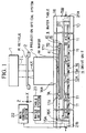
- FIG. 1 is a schematic structural diagram showing a projection exposure apparatus of this embodiment.
- a pattern formed on the lower side of a reticle R is illuminated by exposure light IL (a line spectrum such as an i beam of a mercury lamp, or an excimer laser beam or the like) from an illumination optical system 1, with uniform illuminance distribution, and under the exposure light IL, the pattern in the reticle R is projected onto a predetermined shot region on a semiconductor wafer (hereinafter simply referred to as a "wafer") W via a projection optical system 3 with a predetermined projection magnification ⁇ ( ⁇ is for example 1/4, 1/5 or the like).
- exposure light IL a line spectrum such as an i beam of a mercury lamp, or an excimer laser beam or the like
- the reticle R is held on a reticle stage 2 capable of precise movement in the X direction, the Y direction and the rotation direction, and the position of the reticle stage 2 is controlled based on the measurement of a laser interferometer (not shown).
- the wafer W in thin disk form in this embodiment is held on a wafer holder 4 (see FIG. 2) by means of, for example electrostatic attachment, and the wafer holder 4 is fixed on a wafer table 5 having an overall rectangular and flat shape.
- the wafer table 5 in this embodiment is obtained by laminating together in order from the wafer holder 4 side, a ceramic plate 6 as a non-magnetic material and one magnet plate 8 which generates a uniform magnetic flux in the Z direction.
- the magnet plate 8 is one permanent magnet in which, for example the bottom face side is the N-pole, and the upper face side is the S-pole (the reverse is also possible).
- a flat bottom yoke 10 comprising a ferromagnetic body is arranged at the bottom face side of the wafer table 5 so as to cover the whole face of the moving range of the wafer table 5, and the bottom yoke 10 is installed on a floor (not shown) directly or via a vibration-isolating mechanism such as a rubber vibration isolator.
- Multiple drive units 11 are attached on the upper face of the bottom yoke 10, and the drive circuit of each drive unit 11 is incorporated in a wafer table drive system 23.
- the drive units 11 respectively impart variable thrust (to be described later in detail) in the X direction, the Y direction and the Z direction to the magnet plate 8 (thus also to the wafer table 5).
- These drive units 11 are covered with a cover member 21 comprising a thin plate of a non-magnetic material which provides a narrow cavity portion.
- the cover member 21 also functions as a cooling apparatus for the drive units 11, and a refrigerant comprising a low temperature liquid is fed from a refrigerant feeder (not shown), to the cavity portion of the cover member 21 via a supply port 21a.
- the refrigerant which has flowed in the cover member 21 and which has absorbed heat generated from the multiple drive units 11 is returned to the refrigerant feeder from a discharge port 21b.
- the quantity of heat generated in each drive unit 11 in this embodiment is small, however even this small quantity of heat generated is carried to the outside by the refrigerant in the cover member 21. Hence the increase in the temperature of the wafer table 5 is small, and positioning is performed with high precision.
- a flat top yoke 16 comprising a ferromagnetic body is arranged on the upper side face of the wafer table 5, and a tip portion of the projection optical system 3 is inserted into an opening 16a in a central portion of the top yoke 16.
- a lens-barrel of the projection optical system 3 is formed from a ferromagnetic body, and the tip portion of the projection optical system 3 becomes a part of the top yoke 16.
- the bottom yoke 10 and the top yoke 16 are coupled by supports 15A to 15D (in FIG. 1, only 15A and 15B can be seen) comprising a ferromagnetic body at four corners, so that the bottom yoke 10, the magnet plate 8, the top yoke 16 and the supports 15A, 15B and the like form a first closed magnetic circuit.
- the supports 15A to 15D may be provided with a vibration isolation member (for example, a spring member comprising a ferromagnetic body).
- a second magnetic circuit is also formed wherein the magnetic flux leaked into space from the N-pole of the magnet plate 8 returns to the S-pole of the magnet plate 8 through the top yoke 16.
- a steady state force for lifting is given to the wafer table 5 mainly by the second magnetic circuit.
- columnar soft touchdown members 7A to 7C (see FIG. 2) comprising a synthetic rubber or the like are fixed at three points on the periphery of the wafer holder 4 on the upper face of the wafer table 5, so that even if the wafer table 5 is attracted toward the top yoke 16, the impact force is absorbed by the touchdown members 7A to 7C.
- An X axis movable minor 17X is fixed to the - X direction end portion of the upper face of the plate 6 of the wafer table 5, and a Y axis movable mirror 17Y is fixed to the + Y direction end portion.
- a laser beam from a laser interferometer 18X is irradiated parallel with the X axis onto the movable mirror 17X, and laser beams from two laser interferometers 18Y1, 18Y2 (see FIG. 2) arranged in parallel are irradiated parallel with the Y axis onto the movable mirror 17Y.
- the laser interferometers 18X, 18Y1 and 18Y2 respectively measure the displacement of the corresponding movable mirrors 18X, 18Y, with a resolution of for example 0.001 ⁇ m to 0.01 ⁇ m, and the measurement result is output to a main control system 22 which generally controls the operation of the whole apparatus in FIG. 1.
- the X coordinate and the Y coordinate of the wafer table 5 can be respectively determined from, for example the mean value of the measurement of the laser interferometer 18X and the measurements of the laser interferometers 18Y1 and 18Y2, while the rotation angle of the wafer table 5 can be determined from the difference of the measurements of the two Y axis laser interferometers 18Y1 and 18Y2.
- the main control system 22 controls the thrust due to the multiple drive units 11 arranged at the bottom face side of the wafer table 5 via the wafer table drive system 23, based on these measurements, and performs positioning of the wafer table 5 (wafer W).
- a focal position detection system of an oblique incidence method type which projects a slit image or the like onto the surface of the wafer W, and detects a defocused quantity of the wafer W from a side slip quantity of the slit image reimaged by the reflected light from the wafer W.
- the main control system 22 controls the position in the Z direction and the angle of inclination of the wafer W by an autofocus method, to thereby align the surface of the wafer W with the image surface in the projection optical system 3.
- the thrust in the X direction, the Y direction and the Z direction is imparted to the magnet plate 8 of the wafer table 5 in this embodiment, by means of the multiple drive units 11 arranged at the bottom face thereof.
- the multiple drive units 11 arranged at the bottom face thereof.
- FIG. 2 is a perspective view of FIG. 1 with the top yoke 16 and the cover member 21 in FIG. 1 partially cut away.
- multiple drive units 11 in this example, in 7 rows x 7 columns
- the array pitch of the drive units 11 is so set that the drive units 11 are always collectively arranged in at least 3 rows x 3 columns at the bottom face of the wafer table 5.
- Each drive unit 11 respectively comprises; a core 20, X coils 12A and 12B which are coils for imparting a thrust in the X direction to the magnet plate 8 (wafer table 5), Y coils 13A and 13B which are coils for imparting a thrust in the Y direction to the magnet plate 8 (wafer table 5), and a Z coil 14 for generating a magnetic flux in the Z direction.
- FIG. 3 (a) is a plan view showing a core 20 for the drive unit 11 comprising a ferromagnetic body
- FIG. 3 (b) is a side view thereof.
- the section of the core 20 is in a shape with four flange portions 20b to 20e also sewing as rectangular bobbins attached on the upper side face of a square pillar 20a.
- the magnetic flux BA passing through the flange portions 20b to 20e is bent and passes through the inside of the square pillar 20a.
- the magnetic flux is practically non existent on the bottom face of the flange portions 20b to 20e.
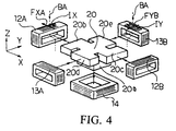
- FIG. 4 is an exploded perspective view showing the drive unit 11.
- the core 20 In the condition installed on the bottom yoke 10, then as shown in FIG. 4, the core 20 is positioned so that the flange portions 20b and 20c face the - X direction and the + X direction respectively.
- the X coils 12A and 12B are wound respectively around the flange portions 20b and 20c in the X direction of the core 20, that is, around the axis parallel with the X axis
- the Y coils 13A and 13B are wound respectively around the flange portions 20d and 20e in the Y direction of the core 20, that is, around the axis parallel with the Y axis
- the Z coil 14 is wound around the square pillar 20a at the bottom of the core 20, that is, around the axis parallel with the Z axis, thereby constructing the drive unit 11.
- Other drive units are constructed in the same manner.
- the electric current IX flowing for example in the + Y direction (or - Y direction) on the upper part and in the - Y direction ( or + Y direction) on the bottom part is supplied to the X coil 12A, but since the magnetic flux BA passing through the upper part of the X coil 12A does not pass through the bottom part due to the action of the core 20, a Lorentz force FXA in the X direction acts on the X coil 12A as a whole. A Lorentz force in the X direction similarly acts on the X coil 12B.
- the electric current IY flowing, for example in the - X direction (or + X direction ) on the upper part and in the + X direction (or - X direction) on the bottom part is supplied to the Y coil 13B, but since the magnetic flux BA passing through the upper part of the Y coil 13B does not pass through the bottom part, a Lorentz force FYB in the Y direction acts on the Y coil 13B as a whole, while a Lorentz force in the Y direction similarly acts on the other Y coil 13A.
- variable repulsion or attraction is generated with respect to the magnet plate 8 above the core 20.
- the Z coil 14 is arranged in the vicinity of the junction of the core 20 and the bottom yoke 10, under the X coils 12A, 12B and the Y coils 13A and 13B. Since the Z coil 14 surrounds the whole junction, it can give a magnetomotive force to the entire core 20. Therefore, it can give a relatively linear thrust in the Z direction with respect to the wafer table 5.
- the Z coil 14 gives the magnetomotive force partially to the core 20
- a local magnetic circuit is formed in the core 20, and the force generated by the Z coil 14 becomes very non-linear, and for example, even if it is tried to lift the wafer table 5, an attraction may act on the wafer table 5.
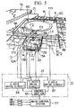
- FIG. 5 is an enlarged view of part of FIG. 2.
- the magnetic flux BA going, for example in the - Z direction from the magnet plate 8 to the drive unit 11 is generated by means of the magnet plate 8 in the wafer table 5, and the bottom yoke 10, the top yoke 16 and the like in FIG. 2.
- a drive circuit 31 is connected to the drive unit 11, and a control section 35 in the drive circuit 31 controls the operation of each circuit under the instruction from the main control system 22.
- an X-axis drive circuit 32, a Y-axis drive circuit 33 and a Z-axis drive circuit 34 are provided.
- the X-axis drive circuit 32 supplies the electric current IX flowing in the Y direction on the upper part of the X coils 12A and 12B of the corresponding drive unit 11
- the Y-axis drive circuit 33 supplies the electric current IY flowing in the X direction on the upper part of the Y coils 13A and 13B
- the Z-axis drive circuit 34 supplies the electric current IZ to the Z coil 14.
- a Lorentz force in the Y direction is generated in the Y coils 13A and 13B, by means of the current IY flowing in the Y coils 13A and 13B and the magnetic flux BA in the Z direction, and a thrust FY in the Y direction is generated in the magnet plate 8 (wafer table 5) as a reaction force to the Lorentz force.
- the thrust FX, FY is proportional to the respective currents IX, IY, the X-axis drive circuit 32 and the Y-axis drive circuit 33 respectively control the currents IX and IY according to the thrust instruction from the control section 35.
- the direction of the thrust IX and IY ( ⁇ X direction, and ⁇ Y direction) can be optionally set according to the direction of the corresponding respective currents IX and IY.
- a new variable magnetic flux passing through the Z coil 14 is generated as described above, and by means of this variable magnetic flux, a thrust FZ in the Z direction comprising a reluctance force acts on the magnet plate 8.
- the thrust FZ can also be set in either the + Z direction (repulsion) or the - Z direction (attraction) according to the direction of the current (sign) supplied to the Z coil.
- a drive circuit the same as the drive circuit 31 in FIG. 5 is respectively connected to each drive unit 11 in FIG. 2, and the wafer table drive system 23 in FIG. 1 is constituted by these multiple drive circuits 31.
- the coordinate in the X direction and the Y direction and the rotation angle of the wafer table 5 at this time can be determined from the measurements of the laser interferometers 18X, 18Y1 and 18Y2.
- the main control system 22 gives an instruction as to how much the wafer table is displaced in each portion, to the control section 35 in the drive circuit 31 of each drive unit 11, and the control section 35 generates predetermined thrusts by means of the corresponding coils, according to this instruction.
- the wafer table 5 can be positioned with six degrees of freedom (displacement in the X direction, Y direction and Z direction, and rotation around the X axis, Y axis and Z axis), by combining the thrusts FX, FY, FZ in the X direction, Y direction and Z direction generated from these drive units 11 with respect to the magnet plate 8 (wafer table 5).
- strain gauges 9A to 9D are adhered at four corners on the upper face of the plate 6 of the wafer table 5 of this embodiment. These strain gauges 9A to 9D are connected to a detection circuit (not shown) via a lead (not shown) having flexibility, and the strain quantity of the plate 6 detected by the detection circuit is supplied to the main control system 22. When strain of the magnet plate 8 and the plate 6 is detected, the main control system 22 corrects the strain by controlling the thrust in the Z direction by means of the plurality of drive units 11 at the bottom face of the wafer table 5.
- the strain of the magnet plate 8 may be corrected independently by adhering a correcting plate comprising a magnetostrictive material which deforms according to the magnetic field, to the upper face or the bottom face of the magnet plate 8, rather than by correcting the strain actively in the above described manner.
- a magnetostrictive material for example, a ferrite garnet type (CoFe 2 O 4 or the like) or a rare-earth alloy type (70 % by weight Tb - 30 % by weight Fe, SmFe 2 , TbFe 2 , Tb(CoFe) 2 or the like) can be used.
- the magnetostrictive material when used, then for example at a position where the magnet plate 8 tends to be distorted in a convex shape due to the magnetic field, a magnetostrictive material which contracts due to the magnetic field can be adhered, and at a position where the magnetism generation body tends to be distorted in a concave shape due to the magnetic field, a magnetostrictive material which expands due to the magnetic field can be adhered.
- the main control section 22 gives an instruction to generate the thrust FY1 in the Y direction to the control sections of the plurality of drive units 11A, 11B and 11C at the bottom face of the wafer table 5.
- the thrust FY1 in the Y direction acts on the wafer table 5 from the drive units 11A to 11C, to thereby displace the wafer table 5 in the Y direction.
- the thrust FX1 in the X direction can be made to act on the wafer table 5 from the plurality of drive units 11D, 11B and 11E at the bottom face of the wafer table 5.
- the wafer table 5 on which the wafer W is mounted is driven in a non-contact state, the wafer W can be positioned at a high speed. Therefore, the throughput (productivity) of the exposure process is increased. Moreover, since the drive units 11 need only be arranged approximately over the whole face in the moving range of the wafer table 5, the positioning apparatus does not become large. Furthermore, for example in FIG. 1, the wafer W can be replaced through a notch portion (not shown) provided at the end portion of the top yoke 16.
- the drive unit 11 may be disposed at the upper face side of the wafer table 5, or may be disposed at both the upper face and the bottom face sides of the wafer table 5. By disposing the drive unit 11 at both sides, a large thrust can be obtained.
- a focal position detection system of an oblique incidence method (not shown) for measuring the position in the Z direction on the surface of the wafer W is provided.
- a plurality of gap sensors may be provided on the bottom yoke 10 side, for measuring the space with the wafer table 5.
- FIG. 7 to FIG. 9 uses a drive unit different from that of the first embodiment. Similar parts corresponding to those in FIG. 1 and FIG. 2 are denoted by the same reference numerals in FIG. 7 to FIG. 9, and detailed description thereof is omitted.
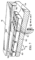
- FIG. 7 is a sectional view showing the main parts on the wafer stage side of the projection exposure apparatus of this embodiment.
- a top yoke 16 is fixed via supports 15C, 15D etc., above a bottom yoke 10.
- a plurality of drive units 60 are arranged at a predetermined pitch in the X direction and the Y direction on the bottom yoke 10, so as to cover the whole face of the moving plane of the wafer table 5, and the wafer table 5 (the bottom thereof is a magnet plate 8) is arranged on the plurality of drive units 60.
- a first magnetic circuit comprising the bottom yoke 10, the magnet plate 8 in the wafer table 5, the top yoke 16 and the supports 15C, 15D etc., and a second magnetic circuit where the magnetic flux leaking into space from the bottom face of the magnet plate 8 returns to the magnet plate 8 through the top yoke 16 are formed, and the force for lifting toward the top yoke 16 side acts on the wafer table 5 principally by means of the second magnetic circuit.
- drive units 60 always in about 3 rows x 3 columns are arranged at the bottom face of the wafer table 5.
- the drive units 60 also comprise X coils 27A and 27B for imparting a thrust in the X direction, Y coils 28A and 28B for imparting a thrust in the Y direction and a Z coil 29 for imparting a thrust in the Z direction, each with respect to the magnet plate 8.
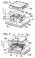
- FIG. 8 shows a condition with one drive unit 60 in FIG. 7 disassembled.
- inverse U-shaped cores 25A and 25B parallel with the X direction are arranged diagonally on the bottom yoke 10
- inverse U-shaped cores 26A and 26B parallel with the Y direction are arranged on an opposite diagonal to that of the cores 25A and 25B.
- the drive unit 60 is constructed such that, as shown by the two dot chain lines, the X coils 27A and 27B are wound around the axis parallel with the X axis at the upper part of the cores 25A and 25B, and the Y coils 28A and 28B are wound around the axis parallel with the Y axis at the upper pan of the cores 26A and 26B, and as shown by solid lines, the Z coil 29 is wound around the axis parallel with the Z axis so as to surround these cores.
- the magnetic flux generated by the X coil 27A forms a closed magnetic circuit comprising the core 25A and the bottom yoke 10, as shown by the route 30, and does not affect the other cores 25B, 26A and 26B.
- the control precision of the thrust in the X direction and the Y direction is improved.
- FIG. 9 As the drive circuit of the drive unit 60, the drive circuit 31 in FIG. 5 of the first embodiment can be utilized.
- a Lorentz force is generated in the X direction by means of the current IX flowing through the X coils 27A and 27B and the magnetic flux BA in the Z direction, and a thrust FX in the X direction as the reaction force thereto is generated in the magnetic plate 8 (wafer table 5).
- a Lorentz force is generated in the Y direction by means of the current IY flowing through the Y coils 28A and 28B and the magnetic flux BA in the Z direction, and a thrust FY in the Y direction as the reaction force thereto is generated in the magnetic plate 8.
- a thrust FZ repulsion or attraction
- FIG. 14 to FIG. 17 This embodiment also uses a drive unit different from those of the above described embodiments. Similar parts corresponding to those in FIG. 7 to FIG. 9 are denoted by the same reference numerals in FIG. 14 to FIG. 17, and detailed description thereof is omitted.
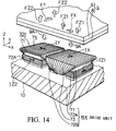
- FIG. 14 is a perspective view showing the main parts of the wafer stage side of the projection exposure apparatus of this embodiment.
- a wafer table 5 is arranged so as to be lifted approximately in a magnetic circuit between a bottom yoke 10 and a top yoke 16 (not shown) (see FIG. 7).
- Two kinds of drive units 70X and 70Y are arranged on the upper face of the bottom yoke 10 alternately at a predetermined pitch in the X direction and the Y direction so as to cover the whole face of the moving plane of the wafer table 5.
- the X axis drive unit 70X gives variable thrust in the Z direction and in the X direction to the magnet plate 8 in the wafer table 5, and the Y axis drive unit 70Y arranged by the rotating a drive unit 70X through 90°, gives variable thrust in the Z direction and in the Y direction to the magnet plate 8 (and the wafer table 5).
- Drive units 70X, 70Y always in about 3 rows x 3 columns are arranged at the bottom face of the wafer table 5, and an overall variable thrust with six degrees of freedom acts on the wafer table 5 (magnet plate 8) by means of these.
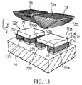
- the drive unit 70X comprises; a core 71 comprising a ferromagnetic body in a convex arch-like shape with respect to the magnet plate 8, that is, in an inverse U-shape with two leg portions fixed on the bottom yoke 10, a horizontal coil 73 wound around an axis approximately parallel with the X axis, on an upper part of the core 71 and serving as a bobbin, and two Z coils 72A, 72B wound around axes parallel with the Z axis consisting of two leg portions of the core 71.
- the horizontal coil 73 of the drive unit 70X corresponds to the X coil
- the horizontal coil 73 of the drive unit 70Y corresponds to the Y coil.
- FIG. 15 shows a condition where the horizontal coils 73 are separated from the drive units 70X and 70Y respectively.
- the horizontal coil 73 of the drive unit 70X is wound around an opening 73c into which an upper portion 71a above a dotted line of the core 71 is inserted.
- the upper portion 73a of the horizontal coil 73 is approximately flat and has an area wider than the upper portion 71a of the core 71, and the coil is narrowed at a lower portion 73b, so that the lower portion 73b can pass between the leg portions 71b and 71c of the core 71.
- the drive unit 70X may be assembled in such a manner that the leg portions 71b, 71c and the upper portion 71a are formed from three separate bar members, and the horizontal coil 73 is wound using a bar member having the same sectional area as that of the upper portion 71a. Then after inserting the upper portion 71a into the opening 73c of the horizontal coil 73, the leg portions 71c, 71b respectively wound with the Z coils 72A and 72B are bolted to the opposite end portions of the upper portion 71a from beneath.
- the drive unit 70X may be assembled in such a manner that after thin plates of an L-shaped ferromagnetic body are alternately inserted into the opening 73c of the horizontal coil 73 from the left and the right sides, thin plates of an I-shaped ferromagnetic body are inserted into the spaces in the left and right sides.
- the other drive unit 70Y can be assembled in the same manner.
- leg portions 71b, 71c of the core 71 are directly and magnetically connected to the bottom yoke 10, respectively, but the leg portions 71b and 71c are not directly and magnetically connected with each other. This is to reduce the inductance of each coil 72A, 72B, 73, to thereby improve the response of the thrust.
- the magnetic flux BA in the magnetic circuit including the magnet plate 8, the core 71 and the bottom yoke 10 faces the Z direction (in FIG. 14, - Z direction). If the current IX in the + Y direction is made to flow in the horizontal coil 73, a Lorentz force in the - X direction is generated in the horizontal coil 73, and a thrust FX in the + X direction as the reaction is generated in the wafer table 5 (magnet plate 8). By controlling the direction and the size of the current IX, the direction and the size of the thrust FX with respect to the wafer table 5 can be controlled.
- a variable thrust FY in the Y direction can be generated with respect to the wafer table 5. Since the flux density is small in portions other than the upper portion 73a of the horizontal coil 73, a Lorentz force in the reverse direction is barely generated, for example, at the lower portion 73b of the horizontal coil 73 (see FIG. 15). This is because the magnetic flux coming out from the magnet plate 8 flows to the bottom yoke 10 through the core 71 which is a ferromagnetic body.
- the Z coils 72A and 72B are arranged on the lower side of the horizontal coil 73 and in the vicinity of the junction of the core 71 and the bottom yoke 10. Since the Z coils 72A and 72B substantially surround the entire junction, by flowing a current IZ1 around the Z axis to the Z coils 72A and 72B of the drive unit 70X, a magnetomotive force can be given to the entire core 71. Therefore, a relatively linear thrust FZ1 in the Z direction can be given to the wafer table 5 (magnet plate 8). Furthermore, by controlling the current IZ2 flowing in the Z coils 72A and 72B of the other drive unit 70Y to control the thrust FZ2 in the Z direction with respect to the wafer table 5, leveling of the wafer table 5 can be performed.
- FIG. 16 shows a disassembled condition of one X axis drive unit 74X of this modified embodiment.
- a core 75 comprising a rectangular, thick and flat ferromagnetic body is fixed on the bottom yoke 10, and a pair of horizontal coils 73d and 73e each wound around an axis (opening 73c) parallel with the X axis, are mounted so as to have an upper portion of the core 75 between them in the X direction.
- the horizontal coils 73d and 73e are respectively equivalent to half coils in the - X direction and + X direction, in the case where the horizontal coil 73 in FIG. 14 is divided into half symmetrically on a plane parallel with the ZY plane.
- the drive unit 74X is constructed by mounting a Z coil 76 wound in a rectangular frame form around the Z axis, so as to surround the core 75 and the horizontal coils 73d and 73e.
- FIG. 17 is a sectional view along the line AA in FIG. 16, showing the condition where the wafer table 5 is located on the drive unit 74X.
- a magnetic flux BA passes the horizontal coils 73d and 73e on the upper face of the core 75 in the Z direction by means of the magnetic circuit including the magnet plate 8 of the wafer table 5, the core 75, and the bottom yoke 10. Therefore, by making a current IX1 flow through the horizontal coils 73d and 73e in the Y direction (see FIG. 16), a variable thrust FX in the X direction is generated as the reaction to the Lorentz force generated in the horizontal coils 73d, 73e, in the magnet plate 8 (wafer table 5).
- FIG. 10 and FIG. 11 Next is a description of a fourth embodiment of the present invention with reference to FIG. 10 and FIG. 11.
- a positioning apparatus which uses charged particle beams to transfer a mask pattern, for example an electron beam transfer apparatus. Therefore, in this embodiment is shown an example of a positioning apparatus which can also be used for an electron beam transfer apparatus, by constructing so that the wafer does not have to pass through the magnetic flux.
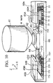
- FIG. 10 shows the main part of the projection exposure apparatus of this embodiment.
- a mask pattern (not shown) is transferred to a wafer W via a projection optical system 41.
- the projection optical system 41 other than an optical type projection optical system which projects a pattern image based on ultraviolet radiation such as an excimer laser beam, an electron optical system or the like which transfers a reduced size image of the mask pattern based on an electron beam can be used.
- an optical type projection optical system which projects a pattern image based on ultraviolet radiation
- an electron optical system or the like which transfers a reduced size image of the mask pattern based on an electron beam
- the wafer W is suction attached and held on a wafer holder 42, and the wafer holder 42 is fixed on a specimen support 43.
- the specimen support 43 is fixed on a central portion of a movable plate 44 of an elongate non-magnetic material approximately along the X axis.
- Rectangular plate-like magnet plates 45A and 45B which generate uniform magnetic fluxes towards for the Z direction are respectively fixed on the bottom face of the + X direction end portion 44a and the - X direction end portion 44b of the movable plate 44.
- the magnet plates 45A and 45B are each a permanent magnet with, for example, the bottom face being the N-pole and the upper face being the S-pole.
- a yoke plate 46 comprising a ferromagnetic body is arranged on the bottom side of the movable plate 44, and opposite end portions 46a and 46b of the yoke plate 46 are respectively formed in a letter "U" shape so as to have the magnet plates 45A and 45B at the opposite end portions of the movable plate 44, between upper and lower portions thereof.
- the drive units 11 on the + X direction side have the same construction as that of the drive units 11 in the first embodiment shown in FIG. 5. In FIG. 5,
- the lifting force is imparted to the + X direction side magnet plate 45A at the center of the yoke plate 46, and a thrust fX1 in the X direction, a thrust fY1 in the Y direction and a thrust fZ1 in the Z direction act on the magnet plate 45A from the plurality of drive units 11.
- the magnet plate 45A, and consequently the + X direction side end portion 44a of the movable plate 44 is positioned in the X direction, the Y direction and the Z direction in a non-contact state.
- the drive units 11Y on the - X direction side are different from the drive unit 11 in the first embodiment, being drive units for generating only a thrust in the Y direction and in the Z direction.
- FIG. 11 shows the condition at the bottom face of the - X direction side magnet plate 45B in FIG. 10.
- the magnet plate 45B at the bottom face side of the magnet plate 45B, there is always accommodated for example, about 3 rows x 3 columns of drive units 11Y.
- One drive unit 11Y is constructed with respect to the core 20 shown in FIG. 4, by winding the Y coils 13A, 13B around only a pair of flange portions (flange portions 20d, 20e in FIG. 4) in the Y direction, and winding the Z coil 14 so as to surround the bottom portion of the core 20.
- a Lorentz force FYB in the Y direction acts on the Y coil 13B, by means of the magnetic flux BA which comes in from the upper face of the core 20 and is bent inward at the flange portion.
- a Lorentz force in the Y direction acts on the other Y coil 13A.
- a thrust in the Y direction is generated in the magnet plate 45B above these coils.
- a thrust in the Z direction is generated in the magnet plate 45B above the coil.
- the drive unit 11Y can impart a variable thrust in the Y direction and the Z direction to the magnet plate 45B above the drive unit in a non-contact state.
- the lifting force is imparted to the - X direction side magnet plate 45B in the yoke plate 46, and the thrust fY2 in the Y direction and the thrust fZ2 in the Z direction act on the magnet plate 45B from the plurality of drive units 11Y.
- the magnet plate 45B, and consequently the - X direction side end portion 44b of the movable plate 44 is positioned in the Y direction and the Z direction in a non-contact state. Displacement of the end portion 44b in the Y direction means that the movable plate 44 is rotated around the axis parallel with the Z axis.
- the position in the Z direction, the angle of inclination around the X axis, and the angle of inclination around the Y axis of the movable plate 44 can be controlled, and as a result, the wafer W on the specimen support 43 fixed on the movable plate 44 can be positioned with six degrees of freedom.
- the yoke plate 46 of this embodiment has a construction for connecting the yoke plates in the letter "U" shape on the left and right sides. Hence leakage of the magnetic flux to the central portion of the movable plate 44, that is, to the wafer W side becomes very slight. Therefore, the positioning section in this embodiment can also be used as a wafer stage for an electron beam transfer apparatus or the like.
- the drive units 11 and 11Y may be disposed respectively at the upper face side of the magnet plates 45A and 45B, or may be disposed at both the upper face and the bottom face sides of the magnet plates 45A and 45B.
- a core, an X coil, a Y coil and a Z coil are provided in the drive unit 11, and a core, a Y coil and a Z coil are provided in the drive unit 11Y.
- the construction may be such that, for example, four drive units are provided, with two drive units of these comprising only a Z coil, one drive unit comprising a core, an X coil and a Y coil, and the remaining one drive unit comprising a core and only a Y coil.
- FIG. 12 This embodiment is also an example of a positioning apparatus applicable to a charged particles beam transfer apparatus, where the magnetic flux does not act on the wafer W, being the object to be positioned.
- FIG. 12 similar parts corresponding to those in FIG. 10 are denoted by the same reference numerals, and detailed description thereof is omitted.
- FIG. 12 shows the main parts of the projection exposure apparatus of this embodiment.
- a mask pattern (not shown) is transferred to a wafer W via a projection optical system 41.
- the wafer W is suction attached and held on a wafer holder 42, and the wafer holder 42 is fixed on an - X direction end portion 47b of a movable plate 47 of an elongate non-magnetic material approximately along the X axis.
- a base 51 on which the end portion 47b can be mounted at any time is arranged at a predetermined spacing.
- a rectangular plate-like magnet plate 45 which generates a uniform magnetic flux toward the Z direction is fixed on the bottom face of the + X direction end portion 47a of the movable plate 47.
- the magnet plate 45 is a permanent magnet with, for example the bottom face being the N-pole and the upper face being the S-pole.
- a yoke member obtained by connecting a yoke plate 50, four supports 49A to 49D (in FIG. 12, only 49A to 49C can be seen) and a top yoke 48, is arranged so as to have the magnet plate 45 at the end portion of the movable plate 47 between the upper and lower portions thereof, and to cover the whole face of the moving range of the magnet plate 45.
- Multiple drive units 11 are disposed in the X direction and the Y direction at a predetermined pitch on the upper face of the bottom yoke 50 at the bottom of beneath the magnet plate 45.
- the drive units 11 have the same construction as that of the drive units 11 in the first embodiment shown in FIG. 5.
- the lifting force is imparted to the magnet plate 45 in the yoke member, and the thrust fX in the X direction, the thrust fY in the Y direction, the thrust fZ in the Z direction, the torque in the ⁇ direction around the Z axis, the torque around the X axis, and the torque around the Y axis can be imparted to the magnet plate 45 from the plurality of drive units 11.
- the magnet plate 45, and consequently the wafer W on the end portion of the movable plate 47 are positioned with six degrees of freedom by a cantilever systems.
- the part in the magnetic flux is only the + X direction end portion 47a of the movable plate 47, and the magnetic flux barely acts on the wafer W.
- this positioning apparatus can also be used for the wafer stage of an electron beam transfer apparatus or the like.
- the magnet plate 8 has a monopolar construction.
- the table can be similarly positioned also with a multipolar construction.
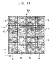
- FIG. 13 shows a plan view of one example of a multipolar magnet plate 8A.
- a plurality of drive units 11 are arranged in the X direction and the Y direction at a predetermined pitch.
- the magnet plate 8A is formed from an array of rectangular plate-like small magnet plates in 4 rows x 4 columns. The polarity of these small magnet plates are reversed alternately both in the X direction and in the Y direction.
- small magnet plates in 2 rows x 2 columns (the ones on the same diagonal have the same polarity, and the ones on the intersecting diagonal have a different polarity to these) in the magnet plate 8A are arranged with respect to one drive unit, and when the magnet plate having the N-pole (or the S-pole) on the bottom face faces the X coil 12, the magnet plate having the S-pole (or the N-pole) on the bottom face faces the Y coil 13. Therefore, by only reversing the polarity of the current flowing in the X coil 12 or in the Y coil 13, the magnet plate 8A can be driven in a similar manner to in the above embodiments.
- a part of the X coil 12 and the Y coil 13 are placed at a magnet plate having a different polarity.
- this part is the portion where the coil is bent in the Z direction, it does not contribute to the thrust in the X direction and in the Y direction.
- a multipolar magnet plate 8A it must be determined to which coil the current should be made to flow according to the position of the magnet plate 8A. Hence the control tends to become complicated.
- FIG. 18 to FIG. 22 This embodiment also uses a drive unit different from that of the first embodiment. Similar parts corresponding to those in FIG. 1 and FIG. 2 are denoted by the same reference numerals in FIG. 18 to FIG. 22, and detailed description thereof is omitted.
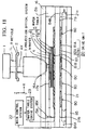
- FIG. 18 is a schematic structural diagram showing a projection exposure apparatus of this embodiment.
- a plate 6 made of ceramic
- a thin plate 77 comprising a ferromagnetic body as a material having high magnetic permeability
- one magnet plate 8 which generates a magnetic flux uniformly in the Z direction
- a thin plate 78 comprising a ferromagnetic body.
- the thin plate 77 on the upper face of the magnet plate 8 is thicker than the thin plate 78 on the bottom face.
- a core plate 79 comprising a core (iron core) as multiple magnetic cores is arranged at the bottom face side of the wafer table 5, and multiple drive units 80 are mounted on the core plate 79.
- Each drive unit 80 comprises; a core, X coils 81A and 81B for imparting a thrust in the X direction to the magnet plate 8 (wafer table 5), Y coils 82A and 82B for imparting a thrust in the Y direction to the magnet plate 8 (wafer table 5), and a Z coil 83 for generating a magnetic flux in the Z direction.
- a drive circuit of each drive unit 80 is incorporated in a wafer table drive system 23.
- the core plate 79 and a top yoke 16 are connected by supports 15A to 15D (in FIG. 18, only 15A and 15B can be seen) comprising ferromagnetic bodies at four corners, and the core plate 79, the magnet plate 8, the top yoke 16 and the supports 15A, 15B and the like form a closed magnetic circuit.
- the ferromagnetic thin plate 77 on the upper face of the magnet plate 8 is thicker than the ferromagnetic thin plate 78 on the bottom face, then in the state with the drive unit 80 not being operated, a force for lifting in the direction of attraction to the top yoke 16 side acts on the magnet plate 8 between the core plate 79 and the top yoke 16.
- the magnet plate 8 By actually generating a thrust for attracting the magnet plate 8 toward the core plate 79 side by means of the drive unit 80, the magnet plate 8 (wafer table 5) is stably supported in a floating state at a desired position in the Z direction.
- a base plate 85 comprising a non-magnetic material is installed via supports 84A and 84B on the bottom face side of the core plate 79, and a tortuous cooling pipe 21 as a cooling apparatus is arranged at the bottom face of the multiple drive units 80 on the base plate 85.
- a refrigerant comprising a low temperature liquid is fed from a refrigerant feeder (not shown) to an inlet 21a of the cooling pipe 21, and the refrigerant which has flowed in the cooling pipe 21 and which has absorbed heat generated from multiple drive units 11 is returned to the refrigerant feeder from an outlet 21b.
- the slight amount of heat generated is carried to the outside by the cooling pipe 21, the increase in the temperature of the wafer table 5 is small, and positioning is performed with high precision.
- the main control system 22 performs positioning of the wafer table 5 (wafer W) by controlling the thrust by means of multiple drive units 80 arranged at the bottom face of the wafer table 5 via the wafer table drive system 23, based on measurements of the X-coordinate and Y-coordinate and the rotation angle of the wafer table 5 (wafer W) by means of laser interferometers 18X, 18Y1, 18Y2, and respectively corresponding movable mirrors 17X and 17Y.
- the thrust in the X direction, the Y direction and the Z direction is imparted by means of the multiple drive units 80 at the bottom face thereof.
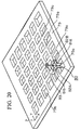
- FIG. 19 is a perspective view of FIG. 18 with the top yoke 16 partially cutaway.
- multiple drive units 80 in this example, in 5 rows x 5 columns
- the array pitch of the drive units 80 is so set that the drive units 80 are always collectively arranged in at least 3 rows x 3 columns at the bottom face of the wafer table 5.
- FIG. 20 shows the core plate 79 in the state where all the drive units except one drive unit 80 are removed from the core plate 79 in FIG. 19.
- the core plate 79 is one in which square through holes 79b are formed in the X direction and in the Y direction at a predetermined pitch on a ferromagnetic flat board. The portions surrounded by four through holes 79b respectively form cruciform cores 79a.
- a pair of X coils 81A and 81B are wound around an axis parallel with the X axis so as to have the cross of the core 79a between them
- a pair of Y coils 82A and 82B are wound around an axis parallel with the Y axis so as to have the cross of the core 79a between them
- a Z coil 83 wound around an axis parallel with the Z axis is adhered to an upper face of the cross of the core 79a, thereby forming one drive unit.
- the other drive units 80 are constructed by respectively mounting the X coils 81A and 81B, the Y coils 82A and 82B, and the Z coil 83 on the cruciform cores 79a, in a similar manner to the drive unit 80 in FIG. 20.
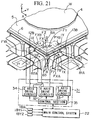
- the drive unit 80 the construction of the drive unit, and the operation of the drive unit 80, with reference to FIG. 21.
- FIG. 21 is an enlarged view of a part of FIG. 19.
- attention is given to one drive unit 80 located at the bottom face of the wafer table 5.
- the magnetic flux BA going, for example in the - Z direction from the magnet plate 8 to the drive unit 80 is generated by means of the magnet plate 8 in the wafer table 5, and the core plate 79, the top yoke 16 and the like in FIG. 19.
- each drive unit 80 is respectively connected to a drive circuit 31, and a control section 35 in the drive circuit 31 controls the operation of each circuit under the instruction from the main control system 22. Therefore, by controlling the current to the X coils 81A and 81B, the Y coils 82A and 82B, and the Z coil 83 by means of an X-axis drive circuit 32, a Y-axis drive circuit 33 and a Z-axis drive circuit 34 in the drive circuit 31, and by combining the thrusts FX, FY and FZ in the X direction, the Y direction and the Z direction on the magnet plate 8 (wafer table 5), the wafer table 5 can be positioned with six degrees of freedom (displacement in the X direction, Y direction and Z direction, and rotation around the X axis, Y axis and Z axis).
- the main control system 22 gives an instruction to generate thrusts FYI in the Y direction to the control sections of the plurality of drive units 80A, 80B and 80C at the bottom face of the wafer table 5.
- the thrusts FY1 in the Y direction act on the wafer table 5 from the drive units 80A to 80C, to thereby displace the wafer table 5 in the Y direction.
- the thrusts FX1 in the X direction can be made to act on the wafer table 5 from the plurality of drive units 80D, 80B and 80E at the bottom face of the wafer table 5.
- the wafer table 5 on which the wafer W is mounted is driven in a non-contact state, the wafer W can be positioned at a high speed.
- a focal position detection system of an oblique incidence method (not shown) for measuring the position in the Z direction on the surface of the wafer W is provided.
- a plurality of gap sensors may be provided on the core plate 79 side, for measuring the space with the wafer table 5.
- FIG. 23 to FIG. 26 uses a drive unit different from that of the first embodiment. Similar parts corresponding to those in FIG. 1 and FIG. 2 are denoted by the same reference numerals in FIG. 23 to FIG. 26, and detailed description thereof is omitted.
- FIG. 23 is a schematic structural diagram showing a projection exposure apparatus of this embodiment.
- a base 86 comprising a rectangular iron board as a material having high magnetic permeability is arranged so as to cover the moving range of the wafer table 5, the base 86 being installed on a bottom yoke 10 comprising a material having high magnetic permeability.
- the base 86 may be a non-magnetic material.
- Multiple drive coils 87, 88 serving as the drive units are installed on the base 86 in a predetermined array so as to face the plane in which the magnet plate 8 of the wafer table 5 moves.
- the drive coils 87 and 88 When the drive coils 87 and 88 are fully contained at the bottom face of the magnet plate 8, the drive coils 87, 88 operate as lifting drive coils which generate a thrust in the - Z direction (attraction) or a thrust in the + Z direction (repulsion) with respect to the magnet plate 8 (wafer table 5).
- the lifting drive coils are also referred to as a "Z leveling coils".
- the drive coils 87, 88 when the drive coils 87, 88 are arranged so as to cross the edge of the magnet plate 8, the drive coils 87, 88 operate as lateral shift drive coils which generate a thrust in the ⁇ X direction or in the ⁇ Y direction with respect to the magnet plate 8 (wafer table 5).
- the lateral shift drive coils are also referred to as "horizontal coils”.
- the drive circuits for these drive coils 87, 88 are incorporated in the wafer table drive system 23.
- the bottom yoke 10, the base 86, the magnet plate 8, the top yoke 16 and the supports 15A, 15B form a closed magnetic circuit.
- the base 86 is a non-magnetic material, the base 86 has no affect on the magnetic circuit. Therefore, even in a state with the drive coils 87 and 88 not being operated, the lifting force acts on the magnet plate 8 (wafer table 5) in the direction of attraction to the top yoke 16 side between the bottom yoke 10 and the top yoke 16.
- the magnet plate 8 By actually generating a thrust attracting the magnet plate 8 toward the bottom yoke 10 side in the drive coils 87, 88 (lifting drive coils), the magnet plate 8 (wafer table 5) is stably supported in a floating state at a desired position in the Z direction.
- the main control system 22 performs positioning of the wafer table 5 (wafer W) by controlling the thrust by means of multiple drive coils 87, 88 arranged at the bottom face of the wafer table 5 via the wafer table drive system 23, based on measurements of the X-coordinate and Y-coordinate and the rotation angle of the wafer table 5 (wafer W) by means of laser interferometers 18X, 18Y1, 18Y2, and respectively corresponding movable mirrors 17X and 17Y.
- the thrust in the X direction, the Y direction and the Z direction is imparted by means of the multiple drive coils 87, 88 at the bottom face thereof.
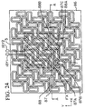
- FIG. 24 is a plan view showing the plane where the drive coils 87, 88 are arranged.
- the drive coils 87, 88 in FIG. 23 are shown in a sectional view along the line AA in FIG. 24.
- the wafer table 5 is represented as a rectangular region with oblique lines.
- drive coil 87 and drive coil 88 are arranged according to a predetermined rule within the base 86 so as to cover the whole region where the wafer table 5 (wafer W) moves.
- One drive coil 87 has a coil wound in a rectangular shape elongate in the Y direction
- the other drive coil 88 is obtained by turning the drive coil 87 through 90°, that is, it has a coil wound in a rectangular shape elongate in the X direction.
- the coils may be wound in an elliptic shape instead of the rectangular shape.
- the drive coils 87 or 88 are always collectively arranged in at least 5 rows X 5 columns at the bottom face of the wafer table 5 (magnet plate 8).
- the array of the drive coils 87, 88 is determined so that no matter what position the wafer table 5 is in, any two or more of the drive coils 87, 88 exist so as to cross the X direction edge portion and the Y direction edge portion of the wafer table 5.
- a drive coil 87C the same as the drive coil 87 and drive coils 88A, 88B the same as the drive coil 88 are completely contained within the bottom face of the wafer table 5, and drive coils 87A, 87B the same as the drive coil 87 are in positions respectively crossing the X direction edge portion and the Y direction edge portion of the wafer table 5. Therefore, the drive coils 87C, 88A and 88B operate as the lifting drive coils, and the drive coils 87A and 87B operate as the lateral shift drive coils.
- FIG. 25 is an enlarged view showing a portion of the drive coils 87A, 87B and the like in FIG. 24.
- a current is respectively supplied to the drive coils 88A located within the bottom face of the wafer table and the drive coils 87A and 87B crossing the edge portion of the wafer table 5, from the drive circuits 91A, 90A and 90B in the wafer table drive system 23.
- a current is also respectively supplied to other drive coils 87, 88 from the corresponding drive circuits.
- the switching control section 89 in the wafer table drive system 23 supplies information about the thrust in the X direction, the Y direction and the Z direction instructed from the main control system 22 to each drive circuit 90A, 90B, and the like.
- the magnetic flux BA going, for example in the - Z direction from the magnet plate 8 to the drive coil 87A is generated by means of the magnet plate 8 in the wafer table 5, and the bottom yoke 10, the top yoke 16 and the like in FIG. 24.
- the main control system 22 discriminates the drive coil 88A completely contained within the bottom face of the wafer table 5 from the drive coils 87A and 87B lying in the position crossing the edges of the wafer table 5, from the measurements of the laser interferometers 18X, 18Y1 and 18Y2, and instructs the switching control section 89 to generate a thrust in the Z direction with respect to the magnet plate 8 (wafer table 5) to the drive coil 88A, and to generate a thrust in the X direction and in the Y direction to the drive coils 87A and 87B, respectively.
- the drive circuit 90A supplies the current IX flowing in the Y direction at the bottom face of the wafer table 5 to the corresponding drive coil 87A
- the drive circuit 90B supplies the current IY flowing in the X direction at the bottom face of the wafer table 5 to the drive coil 87B
- the drive circuit 91A supplies the current IZ to the drive coil 88A.
- a Lorentz force RX is generated in the X direction in the drive coil 87A by means of the current IX flowing in the drive coil 87A and the magnetic flux BA in the Z direction
- a thrust FX in the X direction as the reaction force to the Lorentz force is generated in the magnet plate 8 (wafer table 5).
- a Lorentz force RY is generated in the Y direction in the drive coil 87B
- a thrust FY in the Y direction as the reaction force to the Lorentz force is generated in the magnet plate 8 (wafer table 5).
- the thrusts FX, FY are respectively proportional to the currents IX, IY.
- the drive circuits 90A and 90B respectively set the currents IX, IY according to the thrust instructed from the switching control section 89.
- the direction of these thrusts FX, FY can be optionally set to either direction according to the direction (sign) of the respective corresponding currents IX, IY.
- a new variable magnetic flux BZ passing through the drive coil 88A is generated, and by means of this variable magnetic flux, a thrust FZ in the Z direction comprising a reluctance force acts on the magnet plate 8.
- the thrust FZ can also be set to either the + Z direction (repulsion) or the -Z direction (attraction) according to the direction (sign) of the current IZ supplied to the drive coil 88A.
- the lifting force is imparted to the magnet plate 8 (wafer table 5) by means of the magnetic flux BA, to support the deadweight of the wafer table 5.
- the wafer table 5 can be positioned with six degrees of freedom (displacement in the X direction, Y direction and Z direction, and rotation around the X axis, Y axis and Z axis).
- the main control system 22 gives an instruction to generate thrusts FX1 in the X direction to the drive coils 87A, 87E crossing the X direction edge of the wafer table 5.
- the thrusts FX1 in the X direction act on the wafer table 5 from the drive coils 87A and 87E, respectively, to thereby displace the wafer table 5 in the X direction.
- the thrusts FY1 in the Y direction can be made to act on the wafer table 5 from the drive coils 87B, 87D crossing the Y direction edge of the wafer table 5.
- the wafer table 5 on which the wafer W is mounted is driven in a non-contact state, the wafer W can be positioned at a high speed.
- a coil wound in a rectangular shape is used as the drive coils 87 and 88.
- a coil wound in a square shape or circular shape may be used.
- a focal position detection system of an oblique incidence method (not shown) for measuring the position in the Z direction on the surface of the wafer W is provided.
- a plurality of gap sensors may be provided on the base 86 side, for measuring the space with the wafer table 5.
- the present invention is not limited to the first to the seventh embodiments, and may have various constructions without departing from the gist of the present invention.
- the above described respective embodiments are ones in which the present invention is applied to a batch exposure type projection exposure apparatus.
- the present invention may be applied to a scanning exposure type projection exposure apparatus such as a step and scan method which performs transfer by synchronously scanning the reticle and the wafer with respect to the projection optical system.
- the present invention relates to a positioning apparatus for positioning without contact a movable body on which an object to be positioned, for example, a semiconductor wafer or the like is mounted, a drive unit, and an exposure apparatus incorporating this positioning apparatus.
- a movable table comprising a movable body and a magnetism generation body can be made thin and lightweight.
- the (first) positioning apparatus of the present invention for example most of the deadweight of the movable table is supported by the magnetic circuit comprising a magnetic member and the magnetism generation body, and the force for lifting of the magnetism generation body is controlled by a lifting coil.
- the movable body, on which an object to be positioned, such as a wafer, is mounted can be stably supported in a non-contact state, and that the movable body can be accurately positioned in the height direction with a strong thrust.
- a strong thrust in the height direction can be obtained, a gap between the movable table and the drive unit can be made large, so that there is also the advantage that, for example, a cooling mechanism or the like can be easily arranged in the space of this gap.
- the movable body on which an object to be positioned such as a wafer, is mounted, can be stably supported in a non-contact state, and that the movable body can be accurately positioned two-dimensionally with a strong thrust.
- the drive mechanism does not become large compared to the moving stroke of the movable body, and the movable body can be positioned in a non-contact state.
- the positioning precision increases, and when a deformation quantity measuring system for measuring the deformation quantity of the magnetism generation body is provided, the deformation of the magnetism generation body due to the magnetism can be actively corrected.
- a magnetostriction member which deforms so as to independently offset the deformation due to the magnetism of this magnetism generation body is adhered thereto, the flatness of the magnetism generation body can be maintained with high precision.
- the movable body on which an object to be positioned is mounted can be stably supported in a non-contact state, and that the movable body can be accurately positioned with a strong thrust, similarly as with the above described (first or second) positioning apparatus.
- the positioning apparatus can also be applied for example as a positioning apparatus for a charged particle beam transfer apparatus.
- the positioning apparatus has a construction for dispersing to the floor the reaction force due to the thrust generated at the time of positioning of the movable body, the occurrence of vibration can be suppressed.
- the magnetism generation body is monopolar, the construction is made simple.
- the positioning precision increases.
- the magnetic member has the first to third magnetic members, the assembly and adjustment of the magnetic members becomes easy.
- the movable body and the magnetism generation body are in a flat shape, the movable table can be made thin and lightweight.
- auxiliary magnetic member comprising a material with high magnetic permeability
- the force for lifting by means of the magnetic circuit increases.
- the quantity of heat generation of the lifting coils can be further reduced.
- lifting coils and coils for generating thrust can be made in a unit, and the construction thereof is made simple.
- a cooling apparatus for cooling the drive unit is arranged in the vicinity of the drive unit, the influence of the heat generation of the coils can be further reduced.
- the movable body on which an object to be positioned is mounted can be stably supported in a non-contact state, and that the movable body can be easily positioned in a non-contact state.
- the positioning apparatus of the present invention it is possible to position a movable body at high speed and with high precision, and the apparatus is suitable for use in an exposure apparatus, a test apparatus, a measuring apparatus or the like which requires positioning of a substrate, for example a wafer or the like, at high speed and with high precision.
- the substrate is positioned at high speed by means of the positioning apparatus of the present invention, there is the advantage that a semiconductor device or the like can be produced with high throughput and with high precision.
- the drive unit of the present invention is useful as a drive unit of, for example the (third) positioning apparatus of the present invention, and is suitable for being used for positioning a movable body at high speed and with high precision.
Landscapes
- Engineering & Computer Science (AREA)
- Physics & Mathematics (AREA)
- Chemical & Material Sciences (AREA)
- Combustion & Propulsion (AREA)
- Electromagnetism (AREA)
- Power Engineering (AREA)
- General Physics & Mathematics (AREA)
- Exposure And Positioning Against Photoresist Photosensitive Materials (AREA)
- Exposure Of Semiconductors, Excluding Electron Or Ion Beam Exposure (AREA)
Applications Claiming Priority (9)
| Application Number | Priority Date | Filing Date | Title |
|---|---|---|---|
| JP9224705A JPH1169762A (ja) | 1997-08-21 | 1997-08-21 | 位置決め装置及び該装置を備えた露光装置 |
| JP22470497 | 1997-08-21 | ||
| JP22470597 | 1997-08-21 | ||
| JP9224704A JPH1169764A (ja) | 1997-08-21 | 1997-08-21 | 位置決め装置及び該装置を備えた露光装置 |
| JP27722997 | 1997-10-09 | ||
| JP27722997 | 1997-10-09 | ||
| JP10452498 | 1998-04-15 | ||
| JP10104524A JPH11178311A (ja) | 1997-10-09 | 1998-04-15 | 位置決め装置、駆動ユニット及び前記装置を備えた露光装置 |
| PCT/JP1998/003688 WO1999010970A1 (en) | 1997-08-21 | 1998-08-20 | Positioning device, driving unit, and aligner equipped with the device |
Publications (2)
| Publication Number | Publication Date |
|---|---|
| EP1017155A1 true EP1017155A1 (de) | 2000-07-05 |
| EP1017155A4 EP1017155A4 (de) | 2007-05-02 |
Family
ID=27469227
Family Applications (1)
| Application Number | Title | Priority Date | Filing Date |
|---|---|---|---|
| EP98938909A Withdrawn EP1017155A4 (de) | 1997-08-21 | 1998-08-20 | Positioniervorrichtung, antriebseinheit, und ausrichtvorrichtung mit einer solchen positioniervorrichtung |
Country Status (4)
| Country | Link |
|---|---|
| US (1) | US6259174B1 (de) |
| EP (1) | EP1017155A4 (de) |
| AU (1) | AU8747698A (de) |
| WO (1) | WO1999010970A1 (de) |
Cited By (3)
| Publication number | Priority date | Publication date | Assignee | Title |
|---|---|---|---|---|
| WO2014057386A1 (en) * | 2012-10-09 | 2014-04-17 | Koninklijke Philips N.V. | Positioning device, control device and control method |
| KR20190097170A (ko) * | 2016-12-21 | 2019-08-20 | 칼 짜이스 에스엠테 게엠베하 | 플런저 코일 액추에이터 |
| CN110476339A (zh) * | 2017-03-30 | 2019-11-19 | 日本电产三协株式会社 | 致动器 |
Families Citing this family (35)
| Publication number | Priority date | Publication date | Assignee | Title |
|---|---|---|---|---|
| US6664666B2 (en) * | 1998-12-23 | 2003-12-16 | Engineering Matters, Inc. | Motor assembly allowing output in multiple degrees of freedom |
| TWI248718B (en) * | 1999-09-02 | 2006-02-01 | Koninkl Philips Electronics Nv | Displacement device |
| WO2002031945A2 (en) | 2000-10-13 | 2002-04-18 | Clarity, Llc | Magnetic actuation and positioning |
| JP2002184667A (ja) | 2000-12-14 | 2002-06-28 | Nikon Corp | 補正部材の製造方法、投影光学系の製造方法および露光装置の調整方法 |
| DE10211892A1 (de) * | 2001-03-19 | 2002-12-05 | Canon Kk | Linearer Schrittmotor, Objektträgervorrichtung und Belichtungsvorrichtung |
| US6828890B2 (en) * | 2001-09-26 | 2004-12-07 | Engineering Matters, Inc. | High intensity radial field magnetic array and actuator |
| US6879082B2 (en) * | 2002-03-25 | 2005-04-12 | Clarity Technologies, Inc. | Electromagnetic positioning |
| US7352268B2 (en) * | 2002-09-26 | 2008-04-01 | Engineering Matters, Inc. | High intensity radial field magnetic actuator |
| US6876284B2 (en) * | 2002-09-26 | 2005-04-05 | Engineering Matters, Inc. | High intensity radial field magnetic array and actuator |
| US7136162B1 (en) * | 2002-10-15 | 2006-11-14 | J.A. Woollam Co., Inc. | Alignment of ellipsometer beam to sample surface |
| JP2004228473A (ja) * | 2003-01-27 | 2004-08-12 | Canon Inc | 移動ステージ装置 |
| WO2004093159A2 (en) | 2003-04-09 | 2004-10-28 | Nikon Corporation | Immersion lithography fluid control system |
| JP2004364392A (ja) * | 2003-06-03 | 2004-12-24 | Canon Inc | リニアモータ、及びこれを備えるステージ装置、露光装置並びにデバイス製造方法 |
| JP2005253179A (ja) * | 2004-03-03 | 2005-09-15 | Canon Inc | 位置決め装置、露光装置およびデバイス製造方法 |
| US7006199B2 (en) * | 2004-03-10 | 2006-02-28 | Asml Netherlands B.V. | Lithographic positioning device and device manufacturing method |
| US6948676B1 (en) | 2004-07-06 | 2005-09-27 | Tremblay John K | Method of winding electrical and electronic components |
| JPWO2006006730A1 (ja) * | 2004-07-15 | 2008-05-01 | 株式会社ニコン | 平面モータ装置、ステージ装置、露光装置及びデバイスの製造方法 |
| JP2006199998A (ja) * | 2005-01-20 | 2006-08-03 | Seiko Epson Corp | 成膜装置、成膜方法 |
| JP4738829B2 (ja) * | 2005-02-09 | 2011-08-03 | キヤノン株式会社 | 位置決め装置 |
| US8681314B2 (en) * | 2005-10-24 | 2014-03-25 | Nikon Corporation | Stage device and coordinate correction method for the same, exposure apparatus, and device manufacturing method |
| KR100745371B1 (ko) * | 2006-10-23 | 2007-08-02 | 삼성전자주식회사 | 자기부상형 웨이퍼 스테이지 |
| US8325325B2 (en) | 2008-09-22 | 2012-12-04 | Nikon Corporation | Movable body apparatus, movable body drive method, exposure apparatus, exposure method, and device manufacturing method |
| US8994923B2 (en) * | 2008-09-22 | 2015-03-31 | Nikon Corporation | Movable body apparatus, exposure apparatus, exposure method, and device manufacturing method |
| US8387945B2 (en) * | 2009-02-10 | 2013-03-05 | Engineering Matters, Inc. | Method and system for a magnetic actuator |
| NL2004847A (en) * | 2009-06-30 | 2011-01-04 | Asml Holding Nv | Method for controlling the position of a movable object, a control system for controlling a positioning device, and a lithographic apparatus. |
| NL2009827A (en) * | 2011-12-22 | 2013-06-26 | Asml Netherlands Bv | A stage system and a lithographic apparatus. |
| JP5919395B2 (ja) * | 2012-02-03 | 2016-05-18 | エーエスエムエル ネザーランズ ビー.ブイ. | 可動ステージシステム及びリソグラフィ装置 |
| CN103066894B (zh) * | 2012-12-12 | 2015-05-20 | 清华大学 | 一种六自由度磁悬浮工件台 |
| KR101792390B1 (ko) * | 2016-02-01 | 2017-11-01 | 연세대학교 산학협력단 | 정밀 공간 운동기 |
| JP6814303B2 (ja) * | 2017-09-15 | 2021-01-13 | 株式会社日立ハイテク | イオンミリング装置 |
| DE102018209402A1 (de) * | 2018-06-13 | 2019-12-19 | Robert Bosch Gmbh | Bewegungsvorrichtung mit entkoppelten Positionsreglern |
| ES2890431T3 (es) | 2018-11-23 | 2022-01-19 | Tetra Laval Holdings & Finance | Aparato de capsulado para un sistema de producción de productos alimentarios envasados |
| ES2908671T3 (es) | 2018-11-23 | 2022-05-03 | Tetra Laval Holdings & Finance | Control de flujo en un sistema para la producción de productos alimenticios envasados |
| EP3656707B1 (de) | 2018-11-23 | 2023-03-15 | Tetra Laval Holdings & Finance S.A. | Handhabung von behältern in einem system zur herstellung von verpackten lebensmittelprodukten |
| JP7797104B2 (ja) * | 2021-01-12 | 2026-01-13 | 東京エレクトロン株式会社 | 基板搬送装置、基板搬送方法、および基板処理システム |
Family Cites Families (25)
| Publication number | Priority date | Publication date | Assignee | Title |
|---|---|---|---|---|
| JPS5136441B2 (de) * | 1972-09-08 | 1976-10-08 | ||
| JPS5037169U (de) * | 1973-07-31 | 1975-04-18 | ||
| JPS5254108A (en) | 1975-10-30 | 1977-05-02 | Nippon Telegr & Teleph Corp <Ntt> | Surface pulse motor |
| DE3411895A1 (de) * | 1984-03-30 | 1985-10-10 | Thyssen Industrie Ag, 4300 Essen | Magnetausbildung fuer einen langstatorantrieb |
| JPS6142268A (ja) * | 1984-07-31 | 1986-02-28 | Inoue Japax Res Inc | 送り装置 |
| JPS6176239A (ja) * | 1984-09-25 | 1986-04-18 | Hiroshi Teramachi | リニアモ−タ付xyテ−ブル |
| US4654571A (en) * | 1985-09-16 | 1987-03-31 | Hinds Walter E | Single plane orthogonally movable drive system |
| US4772841A (en) * | 1986-03-08 | 1988-09-20 | Shinko Electric Co., Ltd. | Stepping motor and driving method thereof |
| JPH0799928B2 (ja) * | 1986-12-11 | 1995-10-25 | 株式会社アドバンテスト | X−yリニアモ−タ−の位置検出装置 |
| JP2651732B2 (ja) * | 1990-01-31 | 1997-09-10 | シャープ株式会社 | 直線駆動装置 |
| EP0393994B1 (de) | 1989-04-17 | 1994-06-15 | SHARP Corporation | Linearantriebsgerät |
| JP2665063B2 (ja) * | 1991-03-20 | 1997-10-22 | 三菱重工業株式会社 | 交流磁気浮上搬送装置 |
| JPH04351979A (ja) * | 1991-05-30 | 1992-12-07 | Meidensha Corp | リニアモータの試験装置 |
| JP2716884B2 (ja) * | 1991-07-12 | 1998-02-18 | 住友重機械工業株式会社 | 平面モータ装置 |
| US5196745A (en) | 1991-08-16 | 1993-03-23 | Massachusetts Institute Of Technology | Magnetic positioning device |
| JP2646412B2 (ja) * | 1992-02-18 | 1997-08-27 | キヤノン株式会社 | 露光装置 |
| JPH06254734A (ja) * | 1993-03-02 | 1994-09-13 | Canon Inc | Xyステージ装置およびこれに用いるリニアモータ |
| JPH0748028A (ja) * | 1993-08-06 | 1995-02-21 | Daifuku Co Ltd | 直流リニアモータ利用の移動設備 |
| US5623853A (en) * | 1994-10-19 | 1997-04-29 | Nikon Precision Inc. | Precision motion stage with single guide beam and follower stage |
| JPH0917848A (ja) * | 1995-06-30 | 1997-01-17 | Nikon Corp | 磁気浮上型ステージ |
| US5925956A (en) * | 1995-06-30 | 1999-07-20 | Nikon Corporation | Stage construction incorporating magnetically levitated movable stage |
| US5780943A (en) * | 1996-04-04 | 1998-07-14 | Nikon Corporation | Exposure apparatus and method |
| JPH09322518A (ja) * | 1996-05-28 | 1997-12-12 | Mitsubishi Electric Corp | 永久磁石使用同期形リニアモータ |
| JPH10521A (ja) * | 1996-06-07 | 1998-01-06 | Nikon Corp | 支持装置 |
| US5886432A (en) * | 1997-04-28 | 1999-03-23 | Ultratech Stepper, Inc. | Magnetically-positioned X-Y stage having six-degrees of freedom |
-
1998
- 1998-08-20 EP EP98938909A patent/EP1017155A4/de not_active Withdrawn
- 1998-08-20 WO PCT/JP1998/003688 patent/WO1999010970A1/ja not_active Ceased
- 1998-08-20 AU AU87476/98A patent/AU8747698A/en not_active Abandoned
-
2000
- 2000-02-16 US US09/505,295 patent/US6259174B1/en not_active Expired - Lifetime
Cited By (9)
| Publication number | Priority date | Publication date | Assignee | Title |
|---|---|---|---|---|
| WO2014057386A1 (en) * | 2012-10-09 | 2014-04-17 | Koninklijke Philips N.V. | Positioning device, control device and control method |
| JP2015530866A (ja) * | 2012-10-09 | 2015-10-15 | コーニンクレッカ フィリップス エヌ ヴェ | 位置決めの装置、制御装置及び制御方法 |
| US9507276B2 (en) | 2012-10-09 | 2016-11-29 | Koninklijke Philips N.V. | Positioning device, control device and control method |
| RU2633302C2 (ru) * | 2012-10-09 | 2017-10-11 | Конинклейке Филипс Н.В. | Позиционирующее устройство, управляющее устройство и способ управления |
| KR20190097170A (ko) * | 2016-12-21 | 2019-08-20 | 칼 짜이스 에스엠테 게엠베하 | 플런저 코일 액추에이터 |
| KR102510772B1 (ko) | 2016-12-21 | 2023-03-16 | 칼 짜이스 에스엠테 게엠베하 | 플런저 코일 액추에이터 |
| CN110476339A (zh) * | 2017-03-30 | 2019-11-19 | 日本电产三协株式会社 | 致动器 |
| CN110476339B (zh) * | 2017-03-30 | 2021-05-28 | 日本电产三协株式会社 | 致动器 |
| US11095200B2 (en) | 2017-03-30 | 2021-08-17 | Nidec Sankyo Corporation | Actuator |
Also Published As
| Publication number | Publication date |
|---|---|
| US6259174B1 (en) | 2001-07-10 |
| EP1017155A4 (de) | 2007-05-02 |
| AU8747698A (en) | 1999-03-16 |
| WO1999010970A1 (en) | 1999-03-04 |
Similar Documents
| Publication | Publication Date | Title |
|---|---|---|
| EP1017155A1 (de) | Positioniervorrichtung, antriebseinheit, und ausrichtvorrichtung mit einer solchen positioniervorrichtung | |
| US6720680B1 (en) | Flat motor device and its driving method, stage device and its driving method, exposure apparatus and exposure method, and device and its manufacturing method | |
| JP4174815B2 (ja) | ステージ装置、露光装置、リニアモータ及びリニアモータの駆動方法 | |
| US6885430B2 (en) | System and method for resetting a reaction mass assembly of a stage assembly | |
| US6835941B1 (en) | Stage unit and its making method, and exposure apparatus and its making method | |
| EP0772801B1 (de) | Positionierungsgerät mit einem referenzrahmen für ein messsystem | |
| US5780943A (en) | Exposure apparatus and method | |
| US20100090545A1 (en) | Planar motor with wedge shaped magnets and diagonal magnetization directions | |
| US6144119A (en) | Planar electric motor with dual coil and magnet arrays | |
| US5844664A (en) | Positioning device with a force actuator system for compensating center-of-gravity displacements, and lithographic device provided with such a positioning device | |
| USRE40774E1 (en) | Positioning device with a vibration-free object table, and lithographic device provided with such a positioning device | |
| US6069418A (en) | Electromagnetic motor | |
| US6650079B2 (en) | System and method to control planar motors | |
| US6958808B2 (en) | System and method for resetting a reaction mass assembly of a stage assembly | |
| EP0772800B1 (de) | Lithographisches gerät mit einem sowie horizontal als auch vertikal justierbaren maskenhalter | |
| JPWO2000052744A1 (ja) | ステージ装置及びその製造方法、位置制御方法、露光装置及びその製造方法、並びにデバイス及びその製造方法 | |
| KR100369730B1 (ko) | 리니어모터와스테이지장치및이것을이용한주사형노광장치및디바이스제조방법 | |
| JP2001217183A (ja) | モータ装置、ステージ装置、露光装置及びデバイス製造方法 | |
| US7211908B2 (en) | Magnetic floating device | |
| US20030218732A1 (en) | Stage assembly including a reaction assembly | |
| JP4407774B2 (ja) | モータ装置及びモータ装置の組み立て方法、並びに露光装置 | |
| JPH11178311A (ja) | 位置決め装置、駆動ユニット及び前記装置を備えた露光装置 | |
| US6757053B1 (en) | Stage assembly including a reaction mass assembly | |
| US6989888B2 (en) | Stage system, exposure apparatus, and device manufacturing method | |
| JP2014204634A (ja) | モータ、移動体装置、及び露光装置 |
Legal Events
| Date | Code | Title | Description |
|---|---|---|---|
| PUAI | Public reference made under article 153(3) epc to a published international application that has entered the european phase |
Free format text: ORIGINAL CODE: 0009012 |
|
| 17P | Request for examination filed |
Effective date: 20000222 |
|
| AK | Designated contracting states |
Kind code of ref document: A1 Designated state(s): AT BE CH CY DE DK ES FI FR GB GR IE IT LI LU MC NL PT SE |
|
| A4 | Supplementary search report drawn up and despatched |
Effective date: 20070227 |
|
| RIC1 | Information provided on ipc code assigned before grant |
Ipc: H02N 15/00 20060101ALI20070221BHEP Ipc: H02K 41/03 20060101ALI20070221BHEP Ipc: G03F 7/20 20060101AFI20070221BHEP |
|
| STAA | Information on the status of an ep patent application or granted ep patent |
Free format text: STATUS: THE APPLICATION IS DEEMED TO BE WITHDRAWN |
|
| 18D | Application deemed to be withdrawn |
Effective date: 20070527 |