EP1029749A2 - Générateur de gaz pour coussin gonflable et système de coussin gonflable - Google Patents
Générateur de gaz pour coussin gonflable et système de coussin gonflable Download PDFInfo
- Publication number
- EP1029749A2 EP1029749A2 EP00110891A EP00110891A EP1029749A2 EP 1029749 A2 EP1029749 A2 EP 1029749A2 EP 00110891 A EP00110891 A EP 00110891A EP 00110891 A EP00110891 A EP 00110891A EP 1029749 A2 EP1029749 A2 EP 1029749A2
- Authority
- EP
- European Patent Office
- Prior art keywords
- gas
- combustion
- igniter
- gas generating
- gas generator
- Prior art date
- Legal status (The legal status is an assumption and is not a legal conclusion. Google has not performed a legal analysis and makes no representation as to the accuracy of the status listed.)
- Granted
Links
- 239000003999 initiator Substances 0.000 claims description 95
- 229920005989 resin Polymers 0.000 claims description 22
- 239000011347 resin Substances 0.000 claims description 22
- 239000007789 gas Substances 0.000 abstract description 810
- 238000002485 combustion reaction Methods 0.000 abstract description 514
- 239000000567 combustion gas Substances 0.000 abstract description 88
- WABPQHHGFIMREM-UHFFFAOYSA-N lead(0) Chemical compound [Pb] WABPQHHGFIMREM-UHFFFAOYSA-N 0.000 abstract description 26
- 238000004891 communication Methods 0.000 abstract description 19
- 239000003795 chemical substances by application Substances 0.000 description 230
- 239000003570 air Substances 0.000 description 148
- 238000012546 transfer Methods 0.000 description 120
- 230000002093 peripheral effect Effects 0.000 description 57
- 238000005192 partition Methods 0.000 description 54
- 239000002826 coolant Substances 0.000 description 47
- 230000004913 activation Effects 0.000 description 45
- 239000000463 material Substances 0.000 description 42
- 230000003213 activating effect Effects 0.000 description 30
- 239000000203 mixture Substances 0.000 description 24
- 239000010410 layer Substances 0.000 description 21
- 238000007789 sealing Methods 0.000 description 20
- 230000001133 acceleration Effects 0.000 description 17
- 238000007599 discharging Methods 0.000 description 17
- 239000004065 semiconductor Substances 0.000 description 17
- 230000003111 delayed effect Effects 0.000 description 15
- 238000000034 method Methods 0.000 description 13
- 150000001540 azides Chemical class 0.000 description 9
- 230000008859 change Effects 0.000 description 9
- 238000001816 cooling Methods 0.000 description 8
- 230000001276 controlling effect Effects 0.000 description 6
- 230000002596 correlated effect Effects 0.000 description 6
- 230000007613 environmental effect Effects 0.000 description 6
- 238000004519 manufacturing process Methods 0.000 description 6
- 229910001220 stainless steel Inorganic materials 0.000 description 6
- 238000003466 welding Methods 0.000 description 6
- 230000000875 corresponding effect Effects 0.000 description 5
- 238000005304 joining Methods 0.000 description 5
- 238000000465 moulding Methods 0.000 description 5
- 230000004044 response Effects 0.000 description 5
- 238000012360 testing method Methods 0.000 description 5
- IJGRMHOSHXDMSA-UHFFFAOYSA-N Atomic nitrogen Chemical compound N#N IJGRMHOSHXDMSA-UHFFFAOYSA-N 0.000 description 4
- PXIPVTKHYLBLMZ-UHFFFAOYSA-N Sodium azide Chemical compound [Na+].[N-]=[N+]=[N-] PXIPVTKHYLBLMZ-UHFFFAOYSA-N 0.000 description 4
- 239000012790 adhesive layer Substances 0.000 description 4
- 238000004364 calculation method Methods 0.000 description 4
- 238000002788 crimping Methods 0.000 description 4
- 238000001514 detection method Methods 0.000 description 4
- 230000008569 process Effects 0.000 description 4
- 239000010935 stainless steel Substances 0.000 description 4
- 238000005452 bending Methods 0.000 description 3
- 230000000694 effects Effects 0.000 description 3
- 239000004047 hole gas Substances 0.000 description 3
- 230000007246 mechanism Effects 0.000 description 3
- 230000000452 restraining effect Effects 0.000 description 3
- IDCPFAYURAQKDZ-UHFFFAOYSA-N 1-nitroguanidine Chemical compound NC(=N)N[N+]([O-])=O IDCPFAYURAQKDZ-UHFFFAOYSA-N 0.000 description 2
- XTEGARKTQYYJKE-UHFFFAOYSA-M Chlorate Chemical compound [O-]Cl(=O)=O XTEGARKTQYYJKE-UHFFFAOYSA-M 0.000 description 2
- PXHVJJICTQNCMI-UHFFFAOYSA-N Nickel Chemical compound [Ni] PXHVJJICTQNCMI-UHFFFAOYSA-N 0.000 description 2
- 239000004677 Nylon Substances 0.000 description 2
- 229920002302 Nylon 6,6 Polymers 0.000 description 2
- 229910000831 Steel Inorganic materials 0.000 description 2
- 239000000853 adhesive Substances 0.000 description 2
- 230000001070 adhesive effect Effects 0.000 description 2
- 229910052782 aluminium Inorganic materials 0.000 description 2
- XAGFODPZIPBFFR-UHFFFAOYSA-N aluminium Chemical compound [Al] XAGFODPZIPBFFR-UHFFFAOYSA-N 0.000 description 2
- 239000002585 base Substances 0.000 description 2
- 230000005540 biological transmission Effects 0.000 description 2
- 230000037237 body shape Effects 0.000 description 2
- 230000007547 defect Effects 0.000 description 2
- 239000000446 fuel Substances 0.000 description 2
- 229910052757 nitrogen Inorganic materials 0.000 description 2
- 229920001778 nylon Polymers 0.000 description 2
- 239000007800 oxidant agent Substances 0.000 description 2
- 230000001590 oxidative effect Effects 0.000 description 2
- 229920000728 polyester Polymers 0.000 description 2
- 229920001296 polysiloxane Polymers 0.000 description 2
- 229920002635 polyurethane Polymers 0.000 description 2
- 239000004814 polyurethane Substances 0.000 description 2
- 238000000638 solvent extraction Methods 0.000 description 2
- 239000010959 steel Substances 0.000 description 2
- 229910002651 NO3 Inorganic materials 0.000 description 1
- NHNBFGGVMKEFGY-UHFFFAOYSA-N Nitrate Chemical compound [O-][N+]([O-])=O NHNBFGGVMKEFGY-UHFFFAOYSA-N 0.000 description 1
- 239000000020 Nitrocellulose Substances 0.000 description 1
- 229910052783 alkali metal Inorganic materials 0.000 description 1
- 229910001963 alkali metal nitrate Inorganic materials 0.000 description 1
- 150000001340 alkali metals Chemical class 0.000 description 1
- 229910052784 alkaline earth metal Inorganic materials 0.000 description 1
- 150000001342 alkaline earth metals Chemical class 0.000 description 1
- 239000012080 ambient air Substances 0.000 description 1
- QVGXLLKOCUKJST-UHFFFAOYSA-N atomic oxygen Chemical compound [O] QVGXLLKOCUKJST-UHFFFAOYSA-N 0.000 description 1
- 239000002775 capsule Substances 0.000 description 1
- 238000005266 casting Methods 0.000 description 1
- 238000005520 cutting process Methods 0.000 description 1
- 238000000354 decomposition reaction Methods 0.000 description 1
- 238000013461 design Methods 0.000 description 1
- 238000005242 forging Methods 0.000 description 1
- 238000004868 gas analysis Methods 0.000 description 1
- 230000004048 modification Effects 0.000 description 1
- 238000012986 modification Methods 0.000 description 1
- 229910052759 nickel Inorganic materials 0.000 description 1
- UAGLZAPCOXRKPH-UHFFFAOYSA-N nitric acid;1,2,3-triaminoguanidine Chemical compound O[N+]([O-])=O.NNC(NN)=NN UAGLZAPCOXRKPH-UHFFFAOYSA-N 0.000 description 1
- 229920001220 nitrocellulos Polymers 0.000 description 1
- -1 nitrogen containing organic compound Chemical class 0.000 description 1
- 231100000956 nontoxicity Toxicity 0.000 description 1
- 239000001301 oxygen Substances 0.000 description 1
- 229910052760 oxygen Inorganic materials 0.000 description 1
- 239000008188 pellet Substances 0.000 description 1
- VLTRZXGMWDSKGL-UHFFFAOYSA-M perchlorate Inorganic materials [O-]Cl(=O)(=O)=O VLTRZXGMWDSKGL-UHFFFAOYSA-M 0.000 description 1
- VLTRZXGMWDSKGL-UHFFFAOYSA-N perchloric acid Chemical compound OCl(=O)(=O)=O VLTRZXGMWDSKGL-UHFFFAOYSA-N 0.000 description 1
- 238000007747 plating Methods 0.000 description 1
- 238000003825 pressing Methods 0.000 description 1
- 230000002265 prevention Effects 0.000 description 1
- 230000001737 promoting effect Effects 0.000 description 1
- 238000005096 rolling process Methods 0.000 description 1
- 150000003839 salts Chemical class 0.000 description 1
- 238000007790 scraping Methods 0.000 description 1
- 150000003536 tetrazoles Chemical class 0.000 description 1
- 229920005992 thermoplastic resin Polymers 0.000 description 1
- 229920001187 thermosetting polymer Polymers 0.000 description 1
- 150000003852 triazoles Chemical class 0.000 description 1
Images








Classifications
-
- B—PERFORMING OPERATIONS; TRANSPORTING
- B60—VEHICLES IN GENERAL
- B60R—VEHICLES, VEHICLE FITTINGS, OR VEHICLE PARTS, NOT OTHERWISE PROVIDED FOR
- B60R21/00—Arrangements or fittings on vehicles for protecting or preventing injuries to occupants or pedestrians in case of accidents or other traffic risks
- B60R21/02—Occupant safety arrangements or fittings, e.g. crash pads
- B60R21/16—Inflatable occupant restraints or confinements designed to inflate upon impact or impending impact, e.g. air bags
- B60R21/26—Inflatable occupant restraints or confinements designed to inflate upon impact or impending impact, e.g. air bags characterised by the inflation fluid source or means to control inflation fluid flow
- B60R21/264—Inflatable occupant restraints or confinements designed to inflate upon impact or impending impact, e.g. air bags characterised by the inflation fluid source or means to control inflation fluid flow using instantaneous generation of gas, e.g. pyrotechnic
-
- B—PERFORMING OPERATIONS; TRANSPORTING
- B60—VEHICLES IN GENERAL
- B60R—VEHICLES, VEHICLE FITTINGS, OR VEHICLE PARTS, NOT OTHERWISE PROVIDED FOR
- B60R21/00—Arrangements or fittings on vehicles for protecting or preventing injuries to occupants or pedestrians in case of accidents or other traffic risks
- B60R21/02—Occupant safety arrangements or fittings, e.g. crash pads
- B60R21/16—Inflatable occupant restraints or confinements designed to inflate upon impact or impending impact, e.g. air bags
- B60R21/26—Inflatable occupant restraints or confinements designed to inflate upon impact or impending impact, e.g. air bags characterised by the inflation fluid source or means to control inflation fluid flow
- B60R21/264—Inflatable occupant restraints or confinements designed to inflate upon impact or impending impact, e.g. air bags characterised by the inflation fluid source or means to control inflation fluid flow using instantaneous generation of gas, e.g. pyrotechnic
- B60R21/2644—Inflatable occupant restraints or confinements designed to inflate upon impact or impending impact, e.g. air bags characterised by the inflation fluid source or means to control inflation fluid flow using instantaneous generation of gas, e.g. pyrotechnic using only solid reacting substances, e.g. pellets, powder
-
- B—PERFORMING OPERATIONS; TRANSPORTING
- B01—PHYSICAL OR CHEMICAL PROCESSES OR APPARATUS IN GENERAL
- B01D—SEPARATION
- B01D46/00—Filters or filtering processes specially modified for separating dispersed particles from gases or vapours
- B01D46/24—Particle separators, e.g. dust precipitators, using rigid hollow filter bodies
-
- B—PERFORMING OPERATIONS; TRANSPORTING
- B01—PHYSICAL OR CHEMICAL PROCESSES OR APPARATUS IN GENERAL
- B01D—SEPARATION
- B01D46/00—Filters or filtering processes specially modified for separating dispersed particles from gases or vapours
- B01D46/24—Particle separators, e.g. dust precipitators, using rigid hollow filter bodies
- B01D46/2403—Particle separators, e.g. dust precipitators, using rigid hollow filter bodies characterised by the physical shape or structure of the filtering element
-
- B—PERFORMING OPERATIONS; TRANSPORTING
- B60—VEHICLES IN GENERAL
- B60R—VEHICLES, VEHICLE FITTINGS, OR VEHICLE PARTS, NOT OTHERWISE PROVIDED FOR
- B60R21/00—Arrangements or fittings on vehicles for protecting or preventing injuries to occupants or pedestrians in case of accidents or other traffic risks
- B60R21/02—Occupant safety arrangements or fittings, e.g. crash pads
- B60R21/16—Inflatable occupant restraints or confinements designed to inflate upon impact or impending impact, e.g. air bags
- B60R21/20—Arrangements for storing inflatable members in their non-use or deflated condition; Arrangement or mounting of air bag modules or components
- B60R21/217—Inflation fluid source retainers, e.g. reaction canisters; Connection of bags, covers, diffusers or inflation fluid sources therewith or together
-
- B—PERFORMING OPERATIONS; TRANSPORTING
- B60—VEHICLES IN GENERAL
- B60R—VEHICLES, VEHICLE FITTINGS, OR VEHICLE PARTS, NOT OTHERWISE PROVIDED FOR
- B60R21/00—Arrangements or fittings on vehicles for protecting or preventing injuries to occupants or pedestrians in case of accidents or other traffic risks
- B60R21/02—Occupant safety arrangements or fittings, e.g. crash pads
- B60R21/16—Inflatable occupant restraints or confinements designed to inflate upon impact or impending impact, e.g. air bags
- B60R21/26—Inflatable occupant restraints or confinements designed to inflate upon impact or impending impact, e.g. air bags characterised by the inflation fluid source or means to control inflation fluid flow
-
- B—PERFORMING OPERATIONS; TRANSPORTING
- B01—PHYSICAL OR CHEMICAL PROCESSES OR APPARATUS IN GENERAL
- B01D—SEPARATION
- B01D2279/00—Filters adapted for separating dispersed particles from gases or vapours specially modified for specific uses
- B01D2279/10—Filters adapted for separating dispersed particles from gases or vapours specially modified for specific uses for air bags, e.g. inflators therefor
-
- B—PERFORMING OPERATIONS; TRANSPORTING
- B60—VEHICLES IN GENERAL
- B60R—VEHICLES, VEHICLE FITTINGS, OR VEHICLE PARTS, NOT OTHERWISE PROVIDED FOR
- B60R21/00—Arrangements or fittings on vehicles for protecting or preventing injuries to occupants or pedestrians in case of accidents or other traffic risks
- B60R21/01—Electrical circuits for triggering passive safety arrangements, e.g. airbags, safety belt tighteners, in case of vehicle accidents or impending vehicle accidents
- B60R2021/01006—Mounting of electrical components in vehicles
-
- B—PERFORMING OPERATIONS; TRANSPORTING
- B60—VEHICLES IN GENERAL
- B60R—VEHICLES, VEHICLE FITTINGS, OR VEHICLE PARTS, NOT OTHERWISE PROVIDED FOR
- B60R21/00—Arrangements or fittings on vehicles for protecting or preventing injuries to occupants or pedestrians in case of accidents or other traffic risks
- B60R21/02—Occupant safety arrangements or fittings, e.g. crash pads
- B60R21/16—Inflatable occupant restraints or confinements designed to inflate upon impact or impending impact, e.g. air bags
- B60R21/26—Inflatable occupant restraints or confinements designed to inflate upon impact or impending impact, e.g. air bags characterised by the inflation fluid source or means to control inflation fluid flow
- B60R2021/26029—Ignitors
-
- B—PERFORMING OPERATIONS; TRANSPORTING
- B60—VEHICLES IN GENERAL
- B60R—VEHICLES, VEHICLE FITTINGS, OR VEHICLE PARTS, NOT OTHERWISE PROVIDED FOR
- B60R21/00—Arrangements or fittings on vehicles for protecting or preventing injuries to occupants or pedestrians in case of accidents or other traffic risks
- B60R21/02—Occupant safety arrangements or fittings, e.g. crash pads
- B60R21/16—Inflatable occupant restraints or confinements designed to inflate upon impact or impending impact, e.g. air bags
- B60R21/26—Inflatable occupant restraints or confinements designed to inflate upon impact or impending impact, e.g. air bags characterised by the inflation fluid source or means to control inflation fluid flow
- B60R2021/26064—Inflatable occupant restraints or confinements designed to inflate upon impact or impending impact, e.g. air bags characterised by the inflation fluid source or means to control inflation fluid flow characterised by auto-ignition means
-
- B—PERFORMING OPERATIONS; TRANSPORTING
- B60—VEHICLES IN GENERAL
- B60R—VEHICLES, VEHICLE FITTINGS, OR VEHICLE PARTS, NOT OTHERWISE PROVIDED FOR
- B60R21/00—Arrangements or fittings on vehicles for protecting or preventing injuries to occupants or pedestrians in case of accidents or other traffic risks
- B60R21/02—Occupant safety arrangements or fittings, e.g. crash pads
- B60R21/16—Inflatable occupant restraints or confinements designed to inflate upon impact or impending impact, e.g. air bags
- B60R21/26—Inflatable occupant restraints or confinements designed to inflate upon impact or impending impact, e.g. air bags characterised by the inflation fluid source or means to control inflation fluid flow
- B60R21/263—Inflatable occupant restraints or confinements designed to inflate upon impact or impending impact, e.g. air bags characterised by the inflation fluid source or means to control inflation fluid flow using a variable source, e.g. plural stage or controlled output
- B60R2021/2633—Inflatable occupant restraints or confinements designed to inflate upon impact or impending impact, e.g. air bags characterised by the inflation fluid source or means to control inflation fluid flow using a variable source, e.g. plural stage or controlled output with a plurality of inflation levels
-
- B—PERFORMING OPERATIONS; TRANSPORTING
- B60—VEHICLES IN GENERAL
- B60R—VEHICLES, VEHICLE FITTINGS, OR VEHICLE PARTS, NOT OTHERWISE PROVIDED FOR
- B60R21/00—Arrangements or fittings on vehicles for protecting or preventing injuries to occupants or pedestrians in case of accidents or other traffic risks
- B60R21/02—Occupant safety arrangements or fittings, e.g. crash pads
- B60R21/16—Inflatable occupant restraints or confinements designed to inflate upon impact or impending impact, e.g. air bags
- B60R21/26—Inflatable occupant restraints or confinements designed to inflate upon impact or impending impact, e.g. air bags characterised by the inflation fluid source or means to control inflation fluid flow
- B60R21/264—Inflatable occupant restraints or confinements designed to inflate upon impact or impending impact, e.g. air bags characterised by the inflation fluid source or means to control inflation fluid flow using instantaneous generation of gas, e.g. pyrotechnic
- B60R21/2644—Inflatable occupant restraints or confinements designed to inflate upon impact or impending impact, e.g. air bags characterised by the inflation fluid source or means to control inflation fluid flow using instantaneous generation of gas, e.g. pyrotechnic using only solid reacting substances, e.g. pellets, powder
- B60R2021/2648—Inflatable occupant restraints or confinements designed to inflate upon impact or impending impact, e.g. air bags characterised by the inflation fluid source or means to control inflation fluid flow using instantaneous generation of gas, e.g. pyrotechnic using only solid reacting substances, e.g. pellets, powder comprising a plurality of combustion chambers or sub-chambers
Definitions
- a gas generator for an air bag according to the present invention corresponds to a gas generator in which two combustion chambers are provided in a housing, and is characterized by a structure of arranging two combustion chambers.
- the gas generating means can be suitably selected according to requirements such as a burning rate, a non-toxicity, a combustion temperature, a decomposition starting temperature.
- the gas generating means having different burning rates in the respective combustion chambers may be used the gas generating means having the different composition or composition ratio itself, such that, for example, the inorganic azide such as the sodium azide or the non-azide such as the nitroguanidine is used as the fuel and the nitrogen source.
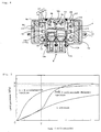
- the gas generating means which is different from the ones in the other chambers in at least one of the burning rate, the shape, the composition, the composition ratio and the amount are stored in a plurality of combustion chambers defined in the housing, and therefore the actuation performance of the gas generator, in particular, the change in the volume of the discharged gas with the passage of time can be characteristically adjusted by independently igniting and burning the gas generating means at an optional timing.
- the combustion chambers are charged by the gas generating means to provide different gas amounts generated at a unit time from each other, respectively.
- a thickness of the first gas generating means to a thickness of the second gas generating means is adjusted to a range between 0.1 : 10 and 10 : 0.1.
- the thickness of the gas generating means can be measured by a method shown in an embodiment mentioned below.
- gas generating means formed in the porous body when using different one at each combustion chamber, it is possible to store gas generating means formed in a porous cylindrical shape (for example, a seven-hole cylindrical body) in one combustion chamber and store gas generating means formed in a single-hole cylindrical shape in another combustion chamber.
- a porous cylindrical shape for example, a seven-hole cylindrical body
- the present invention also provides a gas generator for an air bag comprising, in the housing with the gas discharge port, the ignition means to be activated on an impact and the gas generating means to be ignited and burnt by the ignition means and generate a combustion gas for inflating the air bag, wherein, in the housing, the combustion chambers for storing the gas generating means are defined by partitioning into two or more chambers, and the gas generating means stored in each chamber is ignited and burnt independently by the igniter provided in each chamber and then generates a different amount of a gas per a unit time from each other in each chambers.
- the gas generating means stored in each combustion chamber is independently ignited and burnt by the different ignition means at the same time or at intervals. And by controlling an opening diameter (an opening area) of the gas discharge port and/or the thickness of the seal tape for closing the gas discharge port, the pressure (hereinafter, refer to as "a combustion internal pressure") in the housing at the time when the gas generating means burns can be unified and the combustion performance can be stabilized.
- a combustion internal pressure an opening diameter (an opening area) of the gas discharge port and/or the thickness of the seal tape for closing the gas discharge port
- a gas generator for an air bag wherein two or more igniters contained in the ignition means of the gas generator for the air bag mentioned above are structured such that the igniters are integrated by a resin so as to be aligned to each other in the axial direction.
- a gas generator for an air bag having, in a housing with the gas discharge port, the ignition means to be actuated on an impact, and the gas generating means which is to be ignited and burnt by the ignition means and generate combustion gas for inflating an air bag, wherein the ignition means includes two or more igniters to be activated on an impact and the igniters are integrated by a resin.
- the gas generator for the air bag according to the present invention is a gas generator in which two combustion chambers are provided in the housing, and is characterized by an arrangement structure of two combustion chambers. It is possible to independently ignite and burn the gas generating means stored in the respective combustion chambers by different ignition means.
- a gas generator for an air bag having, in a housing with a gas discharge port, an ignition means to be actuated on an impact, and gas generating means which is to be ignited and burnt by the ignition means and generate a combustion gas for inflating the air bag, wherein two combustion chambers storing the gas generating means are provided in the housing, a communicating hole which allows communication between the combustion chambers is provided, one of the two combustion chambers is provided in a side of the upper space of an inner cylindrical member disposed in the housing, the ignition means is provided in a side of the lower space of the inner cylindrical member, and the upper space and the lower space are defined by a partition wall.
- a gas generator for an air bag having an ignition means to be activated on an impact, and gas generating means which is to be ignited and burnt by the ignition means and generate a combustion gas for inflating the air bag in a housing formed into a cylindrical shape having an axial core length longer than an outermost diameter, with a plurality of gas discharge ports on the peripheral wall thereof, wherein, in the housing, two combustion chambers storing the gas generating means are concentrically provided so as to be adjacent to each other in the axial direction and/or the radial direction of the housing, the communicating hole which allows communication between the combustion chambers is provided, an inner combustion chamber of the two combustion chambers is provided in a side of the upper space of an inner cylindrical member disposed in the housing, the ignition means is provided in a side of the lower space of the inner cylindrical member, and the upper space and the lower space are defined by a partition wall.
- a gas generator for the air bag there can be provided a gas generator for an air bag, wherein an O-ring is interposed between the bent portion of the peripheral edge in the seal cup portion and the inner wall surface of the inner cylindrical member to which the bent portion is fitted.
- two combustion chambers storing the gas generating means are concentrically provided so as to be adjacent to each other in the radial direction of the housing and a communicating hole which allows communication between the combustion chambers is provided.
- two combustion chambers can be concentrically provided so as to be adjacent to each other in the radial direction of the housing and further a communication hole which allows communication between the combustion chambers in the housing can be provided.
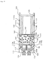
- This seal tape 11 needs to be adjusted on its material and a thickness so that the seal tape is not broken due to the combustion of the gas generating agent 9a in the first combustion chamber 5a but is broken when the gas generating agent 9b in the second combustion chamber 5b is burnt.
- a stainless seal tape having a thickness of 40 ⁇ m is used.
- the through hole 10 does not function to control an internal pressure in the combustion chamber 5b since an opening area thereof is formed larger than a gas discharge port 26b.
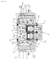
- the initiator collar 13 is formed in a size capable of being inserted into the inner cylindrical member 4, the igniters are easily and securely fixed by crimpig the lower end of the inner cylindrical member 4 so as to fix the initiator collar after inserting the initiator collar 13 provided with two igniters 12a and 12b into the inner cylinder 4.
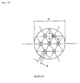
- two igniters (12a, 12b) in the initiator collar 13 a direction of each igniter can be easily controlled.
- two igniters are arranged eccentrically with respect to the center axis of the housing. In case of arranging so as to align the direction of the igniters 12a and 12b, as shown in a back view of the gas generator according to the present embodiment in Fig.
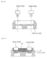
- the separating cylinder 14 arranged between the initiator collar and the partition wall is, as shown in a main portion enlarged view in Fig. 3, arranged so that a hole portions 21 corresponding to an outer shape of the separating cylinder 14 are provided on the lower surface of the partition wall 7 and the upper surface of the initiator collar 13, and the upper end and the lower end of the separating cylinder 14 are fitted into the respective hole portions.
- Fig. 6 is a vertical cross sectional view which shows the other embodiment of a gas generator for an air bag according to the present invention.
- This gas generator is structured such as to be particularly suitable for being arranged in passenger sides.
- a first combustion chamber 305a and a second combustion chamber 305b are partitioned by an inner cylindrical member 304 and provided in the housing 3 so as to be concentrically adjacent to each other.
- a stepped notch portion 306 is provided on an inner peripheral surface of the inner cylindrical member 304 at a predetermined height, and a partition wall 307 which defines the second combustion chamber 305b and an ignition means accommodating chamber 308 is arranged in the stepped notch portion 306.
- the partition wall 307 is, as shown in an exploded perspective view in Fig. 10, constituted by a sectioning circular member 350 engaged with the stepped notch portion 306 of the inner cylindrical member 304 and a seal cup member 360 engaged with the sectioning circular member 350.
- an igniter seal structure comprising the skirt portion of the igniter receiving port 362, the O-ring 381 and the igniter fixing member 382 (hereinafter, referred as "an igniter seal structure"). Accordingly, the flame generated by the activation of any igniter does not directly flow into the space where the other igniter is stored.
- the ignition of the second gas generating agent 309b by the automatic igniting material 385 is performed after a sufficient time more than the normal predetermined delayed time in the case of activating the second igniter 312b has passed (i.e. an interval between activation of each igniter) after the activation of the first igniter 312a. That is, this is different from the matter of delaying the combustion of the second gas generating agent 309b (i.e. delaying the activation of the second igniter 312b) for the purpose of adjusting the actuation performance of the gas generator.
- the seal tape closing the through hole 310 is protected by the shielding plate 386 even when the combustion gas is generated by the combustion of the first gas generating agent 309a, and therefore, the seal tape is not broken by the combustion of the first gas generating agent 309a.
- the through hole 310 of the inner cylindrical member 304 is exclusively opened only by the combustion of the second gas generating agent 309b but is not opened by the combustion of the first gas generating agent 309a.
- the internal pressure at a time of operating the gas generator can be equalized and the combustion performance can be stabilized.
- the gas generator shown in the present embodiment has a long shape in the axial direction since the housing is formed into a long cylindrical shape in the axial direction.
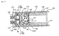
- a gas generator having a simple structure and easily manufactured while the output of the gas generator and the timing for increasing the output can be optionally adjusted by concentrically providing two combustion chambers 105a and 105b so as to be adjacent to each other and making both the combustion chambers communicate with each other.
- Fig. 20 shows another embodiment of an opening portion which is opened by the combustion of the second gas generating agent so as to communicate the first combustion chamber with the second combustion chamber.
- the ignition of the second gas generating agent 309b by the automatic igniting material 385 is performed at a further more delayed time than the predetermined delayed time (that is, an activating interval between the igniters) when normally activating the second igniter 312b after the activation of the first igniter 312a.
- the predetermined delayed time that is, an activating interval between the igniters
- the second gas generating agent 309b is not ignited and burnt by the automatic igniting material 385 during optionally delaying the operating current to the second igniter 312b in order to adjust the operating performance of the gas generator, either.
- the automatic igniting material 385 can be arranged with being combined with the second igniter.
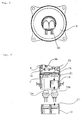
- the ignition means comprises two electric ignition type igniters (12a, 12b) which are activated by an activating signal outputted on the basis of detection by the sensor, and the igniters are fixed to one initiator collar 13 by fitting in parallel to each other so as to align in the axial direction and mounted thereto in a state of exposing head portions thereof.
- the lead wires 50a and 50b which transmit the electric signal (the activating signal) to the igniter can be drawn out in a direction perpendicular to an axial direction of the housing (i.e. the radial direction of the housing) , and at that time, the lead wires 50a and 50b connected to the respective igniters can be drawn out in the same direction.
- the lead wires 50a and 50b which connect the igniter to the control unit (not shown) in the same direction on the same plane.
- the lead wires 50a and 50b are connected to the respective igniters via the respective connectors 51a and 51b, and the connectors 51a and 51b are provided on the same plane in parallel.
- the connectors 51a and 51b in L-letter, the lead wires 50a and 50b which transmit the electric signal (the activating signal) to the igniter can be taken out in a direction perpendicular to an axial direction of the housing (i.e. the radial direction of the housing) , and at that time, the lead wires 50a and 50b connected to the respective igniters can be taken out in the same direction.
Landscapes
- Physics & Mathematics (AREA)
- Engineering & Computer Science (AREA)
- Mechanical Engineering (AREA)
- Fluid Mechanics (AREA)
- Chemical & Material Sciences (AREA)
- Chemical Kinetics & Catalysis (AREA)
- Geometry (AREA)
- Air Bags (AREA)
- Feeding, Discharge, Calcimining, Fusing, And Gas-Generation Devices (AREA)
- Supplying Of Containers To The Packaging Station (AREA)
Applications Claiming Priority (19)
| Application Number | Priority Date | Filing Date | Title |
|---|---|---|---|
| JP27347898 | 1998-09-28 | ||
| JP27347898 | 1998-09-28 | ||
| JP33993498 | 1998-11-30 | ||
| JP33993498 | 1998-11-30 | ||
| JP5712799 | 1999-03-04 | ||
| JP5712799 | 1999-03-04 | ||
| JP7830699 | 1999-03-23 | ||
| JP7830699 | 1999-03-23 | ||
| JP26599599 | 1999-09-20 | ||
| JP26599799 | 1999-09-20 | ||
| JP26599899 | 1999-09-20 | ||
| JP26599599 | 1999-09-20 | ||
| JP26599799 | 1999-09-20 | ||
| JP26599699 | 1999-09-20 | ||
| JP26599999 | 1999-09-20 | ||
| JP26599899 | 1999-09-20 | ||
| JP26599999 | 1999-09-20 | ||
| JP26599699 | 1999-09-20 | ||
| EP99944872A EP1024062B1 (fr) | 1998-09-28 | 1999-09-28 | Generateur de gaz pour coussin gonflable de securite et dispositif de coussin gonflable de securite |
Related Parent Applications (1)
| Application Number | Title | Priority Date | Filing Date |
|---|---|---|---|
| EP99944872A Division EP1024062B1 (fr) | 1998-09-28 | 1999-09-28 | Generateur de gaz pour coussin gonflable de securite et dispositif de coussin gonflable de securite |
Publications (3)
| Publication Number | Publication Date |
|---|---|
| EP1029749A2 true EP1029749A2 (fr) | 2000-08-23 |
| EP1029749A3 EP1029749A3 (fr) | 2001-03-14 |
| EP1029749B1 EP1029749B1 (fr) | 2004-08-18 |
Family
ID=27577056
Family Applications (7)
| Application Number | Title | Priority Date | Filing Date |
|---|---|---|---|
| EP00111122A Expired - Lifetime EP1029750B1 (fr) | 1998-09-28 | 1999-09-28 | Générateur de gaz pour coussin gonflable et système de coussin gonflable |
| EP04030719A Expired - Lifetime EP1518764B1 (fr) | 1998-09-28 | 1999-09-28 | Générateur de gaz pour coussin gonflable et système de coussin gonflable |
| EP00111197A Expired - Lifetime EP1029751B1 (fr) | 1998-09-28 | 1999-09-28 | Générateur de gaz pour coussin gonflable et système de coussin gonflable |
| EP00110656A Expired - Lifetime EP1029748B1 (fr) | 1998-09-28 | 1999-09-28 | Générateur de gaz pour coussin gonflable et système de coussin gonflable |
| EP99944872A Expired - Lifetime EP1024062B1 (fr) | 1998-09-28 | 1999-09-28 | Generateur de gaz pour coussin gonflable de securite et dispositif de coussin gonflable de securite |
| EP00110891A Expired - Lifetime EP1029749B1 (fr) | 1998-09-28 | 1999-09-28 | Moyens de mise à feu pour un générateur de gaz |
| EP00110540A Expired - Lifetime EP1029747B1 (fr) | 1998-09-28 | 1999-09-28 | Générateur de gaz pour coussin gonflable et système de coussin gonflable |
Family Applications Before (5)
| Application Number | Title | Priority Date | Filing Date |
|---|---|---|---|
| EP00111122A Expired - Lifetime EP1029750B1 (fr) | 1998-09-28 | 1999-09-28 | Générateur de gaz pour coussin gonflable et système de coussin gonflable |
| EP04030719A Expired - Lifetime EP1518764B1 (fr) | 1998-09-28 | 1999-09-28 | Générateur de gaz pour coussin gonflable et système de coussin gonflable |
| EP00111197A Expired - Lifetime EP1029751B1 (fr) | 1998-09-28 | 1999-09-28 | Générateur de gaz pour coussin gonflable et système de coussin gonflable |
| EP00110656A Expired - Lifetime EP1029748B1 (fr) | 1998-09-28 | 1999-09-28 | Générateur de gaz pour coussin gonflable et système de coussin gonflable |
| EP99944872A Expired - Lifetime EP1024062B1 (fr) | 1998-09-28 | 1999-09-28 | Generateur de gaz pour coussin gonflable de securite et dispositif de coussin gonflable de securite |
Family Applications After (1)
| Application Number | Title | Priority Date | Filing Date |
|---|---|---|---|
| EP00110540A Expired - Lifetime EP1029747B1 (fr) | 1998-09-28 | 1999-09-28 | Générateur de gaz pour coussin gonflable et système de coussin gonflable |
Country Status (11)
| Country | Link |
|---|---|
| US (4) | US6460883B1 (fr) |
| EP (7) | EP1029750B1 (fr) |
| JP (3) | JP3396214B2 (fr) |
| KR (3) | KR100646586B1 (fr) |
| CN (3) | CN1192923C (fr) |
| AT (7) | ATE526209T1 (fr) |
| AU (1) | AU5761099A (fr) |
| DE (6) | DE69923057T2 (fr) |
| HU (1) | HUP0105172A2 (fr) |
| ID (1) | ID28788A (fr) |
| WO (1) | WO2000018618A1 (fr) |
Families Citing this family (75)
| Publication number | Priority date | Publication date | Assignee | Title |
|---|---|---|---|---|
| JP2000103692A (ja) * | 1998-09-30 | 2000-04-11 | Daicel Chem Ind Ltd | エアバッグ用ガス発生剤組成物成型体 |
| JP3220443B2 (ja) * | 1998-11-30 | 2001-10-22 | ダイセル化学工業株式会社 | エアバッグ用ガス発生器及びエアバッグ装置 |
| US6929284B1 (en) * | 1999-02-05 | 2005-08-16 | Nippon Kayaku Kabushiki-Kaisha | Gas generator |
| JP4757375B2 (ja) * | 2000-09-22 | 2011-08-24 | ダイセル化学工業株式会社 | エアバッグ用ガス発生器 |
| TW469235B (en) | 1999-10-04 | 2001-12-21 | Daicel Chem | Gas generator for air bag and air bag device |
| JP4493790B2 (ja) * | 1999-10-08 | 2010-06-30 | ダイセル化学工業株式会社 | 自動発火機能を有するガス発生器 |
| US6945561B2 (en) | 2000-06-08 | 2005-09-20 | Diacel Chemical Industries, Ltd. | Gas generator for air bag and air bag device |
| JP4864234B2 (ja) * | 2000-06-22 | 2012-02-01 | 株式会社ダイセル | エアバッグ用ガス発生器 |
| EP1331143B1 (fr) * | 2000-10-31 | 2012-08-08 | Daicel Chemical Industries, Ltd. | Generateur de gaz pour airbag et dispositif d'airbag |
| WO2002036525A2 (fr) * | 2000-10-31 | 2002-05-10 | Special Devices, Inc. | Systeme d'amorçage pyrotechnique a amorces multiples |
| DE60225248T2 (de) * | 2001-01-26 | 2009-03-12 | Automotive Systems Laboratory Inc., Farmington Hills | Zweikammer-Gasgenerator |
| US6857658B2 (en) * | 2001-03-15 | 2005-02-22 | Daicel Chemical Industries, Ltd. | Gas generator for air bag and air bag apparatus |
| US6860510B2 (en) * | 2001-08-21 | 2005-03-01 | Daicel Chemical Industries, Ltd. | Multistage inflating-type hybrid inflator |
| US20030146611A1 (en) * | 2002-02-06 | 2003-08-07 | Kenney Steven B. | Adaptive output passenger disk inflator |
| FR2836104B1 (fr) * | 2002-02-21 | 2004-07-09 | Livbag Snc | Dispositif generateur de gaz a sortie axiale utilise en securite automobile, comportant un systeme de diffusion a poussee neutre |
| US7155353B2 (en) * | 2002-04-25 | 2006-12-26 | Daicel Chemical Industries, Ltd. | Method for determining charging capacitance of capacitor |
| US7172214B2 (en) * | 2002-12-09 | 2007-02-06 | Daicel Chemical Industries, Ltd. | Gas generator for air bag |
| JP4113424B2 (ja) * | 2002-12-09 | 2008-07-09 | ダイセル化学工業株式会社 | エアバッグ用ガス発生器 |
| US20040155444A1 (en) * | 2002-12-09 | 2004-08-12 | Naoki Matsuda | Gas generator for air bag |
| US7052040B2 (en) * | 2002-12-09 | 2006-05-30 | Daicel Chemical Industries, Ltd | Gas generator for air bag |
| DE20219898U1 (de) * | 2002-12-23 | 2003-04-30 | TRW Airbag Systems GmbH, 84544 Aschau | Gasgenerator |
| JP4190353B2 (ja) * | 2003-06-03 | 2008-12-03 | ダイセル化学工業株式会社 | 多段着火式ガス発生器 |
| US7150227B2 (en) | 2003-06-03 | 2006-12-19 | Daicel Chemical Industries, Ltd. | Multi-stage ignition type gas generator |
| US7438313B2 (en) * | 2003-08-06 | 2008-10-21 | Arc Automotive, Inc. | Compact multi-level output gas generator |
| JP4490919B2 (ja) * | 2003-08-06 | 2010-06-30 | 日本化薬株式会社 | ガス発生器 |
| JP4994574B2 (ja) | 2004-01-07 | 2012-08-08 | 株式会社ダイセル | ガス発生器用フィルタ |
| US7665764B2 (en) * | 2004-01-15 | 2010-02-23 | Daicel Chemical Industries, Ltd. | Gas generator for air bag |
| US7044502B2 (en) * | 2004-02-24 | 2006-05-16 | Key Safety Systems, Inc. | Dual stage pyrotechnic driver inflator |
| DE102004037277B4 (de) * | 2004-07-31 | 2010-06-17 | Tyco Electronics Amp Gmbh | Elektrischer Mehrfachstecker |
| US7648163B2 (en) * | 2004-08-10 | 2010-01-19 | Daicel Chemical Industries, Ltd. | Gas generator for air bag |
| US7232001B2 (en) * | 2004-08-24 | 2007-06-19 | Sam Hakki | Collision air bag and flotation system |
| JP4407430B2 (ja) * | 2004-08-27 | 2010-02-03 | トヨタ自動車株式会社 | 自動車 |
| JP4621016B2 (ja) | 2004-12-10 | 2011-01-26 | ダイセル化学工業株式会社 | ガス発生器 |
| US8950328B1 (en) | 2004-12-29 | 2015-02-10 | E I Du Pont De Nemours And Company | Methods of fabricating organic electronic devices |
| DE102005011242A1 (de) * | 2005-03-11 | 2006-09-14 | Robert Bosch Gmbh | Sicherheitssystem für Fahrzeuginsassen |
| US7510210B2 (en) | 2005-08-08 | 2009-03-31 | Daicel Chemical Industries, Ltd. | Air bag module |
| CN102180137B (zh) * | 2005-11-23 | 2013-06-19 | 沙普公司 | 用于在车辆发生碰撞时吸收能量的方法和可变能量管理系统 |
| FR2907892B1 (fr) * | 2006-10-26 | 2009-01-30 | Seva Technologies | Generateur de gaz |
| US7722078B2 (en) | 2006-12-18 | 2010-05-25 | Daicel Chemical Industries, Ltd. | Gas generator and restraining device using same |
| US7637979B2 (en) * | 2007-04-26 | 2009-12-29 | Mitsui Engineering & Shipbuilding Co., Ltd. | Fabrication method of diesel particular filter element |
| JP4953998B2 (ja) | 2007-09-18 | 2012-06-13 | 株式会社ダイセル | 人員拘束装置用ガス発生器 |
| US7950693B2 (en) * | 2008-05-20 | 2011-05-31 | Autoliv Asp, Inc. | Dual stage inflator |
| US8282127B1 (en) * | 2008-09-03 | 2012-10-09 | Tk Holdings, Inc. | Gas generating system |
| CN102292244B (zh) * | 2009-01-22 | 2016-04-13 | 奥托里夫Asp股份有限公司 | 安全气囊装置用气体发生器 |
| JP2010247817A (ja) * | 2009-03-24 | 2010-11-04 | Toyoda Gosei Co Ltd | インフレーター |
| JP5530113B2 (ja) * | 2009-03-26 | 2014-06-25 | 株式会社ダイセル | 点火器の固定構造 |
| US8393641B1 (en) | 2009-06-12 | 2013-03-12 | Tk Holdings, Inc. | Gas generator |
| US9051225B1 (en) * | 2009-06-12 | 2015-06-09 | Tk Holdings Inc. | Gas generator |
| US8047569B2 (en) * | 2010-03-12 | 2011-11-01 | Autoliv Asp, Inc. | Multi-stage inflator |
| JP5462049B2 (ja) * | 2010-03-30 | 2014-04-02 | 株式会社ダイセル | ガス発生器 |
| KR101066963B1 (ko) * | 2011-02-14 | 2011-09-22 | 주식회사 시큐어메딕 | 보호장구 장착용 인플레이터 |
| US8661985B2 (en) * | 2012-04-18 | 2014-03-04 | Autoliv Asp, Inc. | Low-profile igniter assemblies adapted for use with inflatable airbag systems |
| JP5945152B2 (ja) | 2012-04-25 | 2016-07-05 | 株式会社ダイセル | ガス発生器 |
| US8556294B1 (en) * | 2012-08-22 | 2013-10-15 | Key Safety Systems, Inc | Airbag inflator |
| CN103625413B (zh) * | 2012-08-28 | 2017-09-29 | 比亚迪股份有限公司 | 一种气体发生剂及其制备方法 |
| JP5965334B2 (ja) * | 2013-02-18 | 2016-08-03 | 株式会社ダイセル | ガス発生器 |
| CN105050867B (zh) * | 2013-03-18 | 2017-06-09 | 株式会社日立系统 | 点火器、点火器组装体及其检测系统以及检测方法 |
| JP6184829B2 (ja) | 2013-10-11 | 2017-08-23 | 株式会社ダイセル | ガス発生器 |
| FR3019178B1 (fr) * | 2014-03-28 | 2017-10-13 | Livbag Sas | Filtre pour generateur de gaz |
| JP6353326B2 (ja) * | 2014-09-16 | 2018-07-04 | 株式会社ダイセル | ガス発生器 |
| JP6563825B2 (ja) * | 2015-02-09 | 2019-08-21 | 株式会社ダイセル | ガス発生器 |
| DE102015118518A1 (de) * | 2015-10-29 | 2017-05-04 | Auto-Kabel Management Gmbh | Zündelement zum Zünden eines pyrotechnischen Stoffes und Zündsystem |
| JP6543560B2 (ja) * | 2015-11-26 | 2019-07-10 | 株式会社ダイセル | ガス発生器 |
| CN112477798B (zh) * | 2016-01-26 | 2022-09-30 | 株式会社大赛璐 | 气体发生器 |
| DE102016113732A1 (de) * | 2016-07-26 | 2018-02-01 | Trw Airbag Systems Gmbh | Gasgenerator mit pyrotechnischem Treibsatz und Verfahren zur Herstellung des Treibsatzes |
| DE112017005654B4 (de) * | 2016-11-10 | 2025-03-06 | Daicel Corporation | Gaserzeuger für eine Airbagvorrichtung mit radialer Trennwand |
| DE102017108798A1 (de) * | 2017-04-25 | 2018-10-25 | Trw Airbag Systems Gmbh | Gasgenerator, gassackmodul, fahrzeugsicherheitssystem, und verfahren zum reinigen eines pyrotechnisch erzeugten gases |
| JP6880505B2 (ja) * | 2017-07-14 | 2021-06-02 | 株式会社ダイセル | 放出装置、及びガス発生器 |
| JP6946097B2 (ja) | 2017-07-21 | 2021-10-06 | 株式会社ダイセル | ガス発生器 |
| JP6954520B2 (ja) | 2017-12-05 | 2021-10-27 | 株式会社ダイセル | 点火器組立体、及びガス発生器 |
| CN111954765B (zh) * | 2018-02-06 | 2022-09-20 | 乔伊森安全系统收购有限责任公司 | 致动器组件及其组装方法 |
| KR102622079B1 (ko) * | 2018-05-29 | 2024-01-09 | 주식회사 다이셀 | 가스 발생기 |
| JP2020114698A (ja) * | 2019-01-17 | 2020-07-30 | 株式会社ダイセル | ガス発生器及びガス発生器用のフィルタ |
| JP7410714B2 (ja) * | 2019-12-26 | 2024-01-10 | 株式会社ダイセル | ガス発生器 |
| CN115871592A (zh) * | 2022-12-22 | 2023-03-31 | 湖北航鹏化学动力科技有限责任公司 | 气体发生器和汽车 |
Citations (5)
| Publication number | Priority date | Publication date | Assignee | Title |
|---|---|---|---|---|
| US4950458A (en) | 1989-06-22 | 1990-08-21 | Morton International, Inc. | Passenger automotive restraint generator |
| US4998751A (en) | 1990-03-26 | 1991-03-12 | Morton International, Inc. | Two-stage automotive gas bag inflator using igniter material to delay second stage ignition |
| JPH08207696A (ja) | 1994-05-04 | 1996-08-13 | Breed Automot Technol Inc | エアバッグ装置 |
| JPH09183359A (ja) | 1995-11-08 | 1997-07-15 | Temic Bayern Chem Airbag Gmbh | ガス発生器を多段点火する装置 |
| DE19620758A1 (de) | 1996-05-23 | 1997-11-27 | Temic Bayern Chem Airbag Gmbh | Gasgenerator |
Family Cites Families (84)
| Publication number | Priority date | Publication date | Assignee | Title |
|---|---|---|---|---|
| DE135005C (fr) | ||||
| US3713667A (en) * | 1971-08-27 | 1973-01-30 | Gen Motors Corp | Occupant restraint system |
| US3877882A (en) * | 1972-07-27 | 1975-04-15 | Talley Industries | Gas generating device |
| US3972545A (en) * | 1975-03-10 | 1976-08-03 | Thiokol Corporation | Multi-level cool gas generator |
| CA1140058A (fr) | 1978-12-18 | 1983-01-25 | Fred E. Schneiter | Dispositif de gonflage au gaz avec filtres refroidisseurs ameliores, et methode de fabrication desdits filtres |
| US4865635A (en) | 1988-08-17 | 1989-09-12 | Talley Automotive Products, Inc. | Filter assembly for non-welded inflator device |
| DE3835356A1 (de) * | 1988-10-17 | 1990-04-19 | Bayern Chemie Gmbh Flugchemie | Gasgenerator |
| JPH03548A (ja) * | 1989-02-10 | 1991-01-07 | Morton Internatl Inc | エアバッグ用二室式膨張器 |
| JPH0545063Y2 (fr) | 1989-05-15 | 1993-11-17 | ||
| JPH0329326A (ja) | 1989-06-26 | 1991-02-07 | Nippon Mining Co Ltd | 接合型電界効果型トランジスタ |
| US4943086A (en) | 1989-06-30 | 1990-07-24 | Morton Thiokol, Inc. | Gas bag inflator with a two welded joint housing |
| JP2638643B2 (ja) | 1989-07-06 | 1997-08-06 | シャープ株式会社 | 電子機器 |
| DE4019677A1 (de) * | 1990-06-20 | 1992-01-09 | Bayern Chemie Gmbh Flugchemie | Airbagsystem |
| DE4025571A1 (de) | 1990-08-11 | 1992-02-13 | Wieland Elektrische Industrie | Mehrpolige geraetesteckvorrichtung |
| US5219178A (en) * | 1990-10-08 | 1993-06-15 | Nippon Koki Co., Ltd. | Air bag inflation gas generator |
| DE4141620C2 (de) * | 1990-12-18 | 1996-04-11 | Trw Inc | Startvorrichtungs- oder Initiatoranordnung für eine Airbagaufblasvorrichtung |
| US5221107A (en) | 1990-12-18 | 1993-06-22 | Trw Inc. | Prefilter assembly |
| US5131679A (en) * | 1990-12-18 | 1992-07-21 | Trw Inc. | Initiator assembly for air bag inflator |
| US5200574A (en) * | 1991-04-05 | 1993-04-06 | Morton International, Inc. | Universal squib connector |
| US5104466A (en) * | 1991-04-16 | 1992-04-14 | Morton International, Inc. | Nitrogen gas generator |
| US5320382A (en) * | 1991-05-31 | 1994-06-14 | Gt-Devices | Pulsed pressure source particularly adapted for vehicle occupant air bag restraint systems |
| JPH05305854A (ja) | 1991-06-21 | 1993-11-19 | Daicel Chem Ind Ltd | 薄板構造のガス発生器 |
| JPH04372177A (ja) | 1991-06-21 | 1992-12-25 | Sanyo Electric Co Ltd | 光起電力装置 |
| JP3029326B2 (ja) | 1991-07-09 | 2000-04-04 | 株式会社東芝 | データ送信装置 |
| JPH0524498A (ja) | 1991-07-26 | 1993-02-02 | Takata Kk | 助手席用エアバツグ装置 |
| JP3097201B2 (ja) | 1991-08-27 | 2000-10-10 | 株式会社ニコン | 露出演算装置 |
| JP2785536B2 (ja) | 1991-09-25 | 1998-08-13 | 松下電器産業株式会社 | マルチチップモジュール及びその製造方法 |
| JPH0582713U (ja) * | 1992-04-15 | 1993-11-09 | 株式会社東海理化電機製作所 | エアバッグ装置用インフレータ |
| JP3082426B2 (ja) * | 1992-05-21 | 2000-08-28 | タカタ株式会社 | エアバッグ用インフレータ |
| US5221109A (en) * | 1992-07-23 | 1993-06-22 | Morton International, Inc. | Airbag inflator having vents to terminate inflation |
| US5346254A (en) * | 1993-02-01 | 1994-09-13 | Trw Inc. | Inflator assembly |
| US5340339A (en) | 1993-02-19 | 1994-08-23 | Alliedsignal Inc. | Wire cover for an air bag inflator |
| US5368329A (en) * | 1993-03-03 | 1994-11-29 | Morton International, Inc. | Dual stage inflator |
| JPH07232613A (ja) | 1993-12-28 | 1995-09-05 | Nippon Kayaku Co Ltd | エアバッグ用ガス発生器およびスクイブ |
| US5847310A (en) | 1993-12-28 | 1998-12-08 | Nippon Kayaku Kabushiki-Kaisha | Squib for an air bag with an auto ignition composition |
| JP3040049B2 (ja) | 1994-04-19 | 2000-05-08 | 本田技研工業株式会社 | ワーク位置決め用治具の仕様データ作成装置 |
| JPH0890259A (ja) | 1994-09-27 | 1996-04-09 | Nippon Kayaku Co Ltd | 圧接バリの整形方法及び整形されたガス発生器 |
| US5468017A (en) | 1994-10-17 | 1995-11-21 | Trw Inc. | Auto ignition package for an air bag inflator |
| US5464249A (en) | 1994-11-09 | 1995-11-07 | Morton International, Inc. | Generant loaded filter assembly and method for its use |
| US5564743A (en) | 1995-03-22 | 1996-10-15 | Morton International, Inc. | Multiple stage air bag inflator system |
| US5613705A (en) | 1995-03-24 | 1997-03-25 | Morton International, Inc. | Airbag inflator having a housing protected from high-temperature reactive generated gases |
| US5799973A (en) * | 1995-04-22 | 1998-09-01 | Temic Bayern-Chemie Airbag Gmbh | Pyrotechnic gas generator with two separate combustion chambers |
| DE19520847B4 (de) | 1995-06-08 | 2005-08-18 | Honda Giken Kogyo K.K. | Vorrichtung zur Gaserzeugung für einen Kraftfahrzeug-Airbag |
| US5643345A (en) | 1995-09-18 | 1997-07-01 | Morton International, Inc. | Automotive air bag filter with support member |
| DE19541583A1 (de) | 1995-11-08 | 1997-05-15 | Temic Bayern Chem Airbag Gmbh | Gasgenerator |
| JPH09207705A (ja) | 1995-11-28 | 1997-08-12 | Nippon Kayaku Co Ltd | エアバッグ用ガス発生器及びその組立方法 |
| JPH09213417A (ja) | 1996-01-30 | 1997-08-15 | Tamura Seisakusho Co Ltd | Acアダプタの出力端子装置 |
| JP3040049U (ja) | 1996-01-30 | 1997-08-05 | モートン インターナショナル,インコーポレイティド | 適応性のあるエアバッグ膨張装置 |
| US5685558A (en) * | 1996-02-06 | 1997-11-11 | Trw Inc. | Air bag inflator mounting |
| US5582428A (en) | 1996-02-28 | 1996-12-10 | Morton International, Inc. | Hybrid adaptive inflator for airbags |
| US5630619A (en) | 1996-02-28 | 1997-05-20 | Morton International, Inc. | Hybrid adaptive inflator for airbags |
| DE19611102A1 (de) * | 1996-03-21 | 1997-09-25 | Dynamit Nobel Ag | Gasgenerator für ein Airbagsystem |
| US6234521B1 (en) | 1996-04-08 | 2001-05-22 | Daicel Chemical Industries, Ltd. | Airbag inflator and an airbag apparatus |
| US5690357A (en) * | 1996-04-25 | 1997-11-25 | Trw Inc. | Dual stage air bag inflator |
| JPH106912A (ja) | 1996-06-26 | 1998-01-13 | Nippon Kayaku Co Ltd | エアバッグ用ガス発生器及びその組立方法 |
| US5882224A (en) | 1996-08-28 | 1999-03-16 | Thomas & Betts International, Inc. | Squib connector socker assembly having shorting clip for automotive air bags |
| JP2989788B2 (ja) | 1996-10-31 | 1999-12-13 | ダイセル化学工業株式会社 | エアバッグ用ガス発生器及びエアバッグ装置 |
| JPH10129400A (ja) | 1996-10-31 | 1998-05-19 | Daicel Chem Ind Ltd | エアバッグ用ガス発生器及びエアバッグ装置 |
| JP3247932B2 (ja) | 1996-12-27 | 2002-01-21 | タイコエレクトロニクスアンプ株式会社 | 点火管コネクタ |
| JP3425319B2 (ja) | 1997-02-10 | 2003-07-14 | ダイセル化学工業株式会社 | エアバッグ用ガス発生器及びエアバッグ装置 |
| JPH10324219A (ja) | 1997-03-26 | 1998-12-08 | Nippon Kayaku Co Ltd | ガス発生器 |
| US5743556A (en) | 1997-04-02 | 1998-04-28 | Lindsey; David W. | Inflator flow inhibitor |
| FR2761942B1 (fr) | 1997-04-11 | 1999-05-07 | Livbag Snc | Generateur pyrotechnique a debit et volume de gaz adaptables pour coussin de protection |
| JPH10297416A (ja) * | 1997-04-25 | 1998-11-10 | Matsushita Electric Ind Co Ltd | エアバッグ装置用ガス発生装置及びエアバッグ膨張方法 |
| DE29708380U1 (de) | 1997-05-09 | 1997-09-04 | TRW Occupant Restraint Systems GmbH, 73553 Alfdorf | Gasgenerator |
| FR2763548B1 (fr) | 1997-05-23 | 1999-06-18 | Livbag Snc | Generateur pyrotechnique de gaz adaptatif a chambres tubulaires pour coussin de protection |
| DE19725452A1 (de) | 1997-06-16 | 1998-12-17 | Temic Bayern Chem Airbag Gmbh | Gasgenerator für eine Sicherheitseinrichtung |
| DE19732825A1 (de) | 1997-07-30 | 1999-02-04 | Temic Bayern Chem Airbag Gmbh | Gassack-Modul |
| EP1002215B1 (fr) | 1997-08-08 | 2001-10-31 | The Whitaker Corporation | Raccord pour airbag |
| JP3702074B2 (ja) * | 1997-08-25 | 2005-10-05 | 日本化薬株式会社 | ガス発生器 |
| FR2768501B1 (fr) | 1997-09-12 | 1999-10-22 | Livbag Snc | Generateur pyrotechnique adaptatif de gaz pour coussin de protection avec dispositif de neutralisation |
| JPH1196868A (ja) | 1997-09-16 | 1999-04-09 | Autoliv Japan Kk | 衝突センサ及びそれを用いたエアバッグ作動制御装置 |
| JPH1191494A (ja) * | 1997-09-18 | 1999-04-06 | Nippon Kayaku Co Ltd | ガス発生器 |
| JP3986184B2 (ja) * | 1997-11-05 | 2007-10-03 | 日本化薬株式会社 | ガス発生器 |
| JPH11159318A (ja) | 1997-11-28 | 1999-06-15 | Mitsubishi Heavy Ind Ltd | 排気ガス中の固形物処理装置 |
| DE19757478A1 (de) | 1997-12-23 | 1999-06-24 | Dynamit Nobel Ag | Pyrotechnischer Gasgenerator |
| JP4014715B2 (ja) | 1997-12-26 | 2007-11-28 | アビックス株式会社 | Ledイルミネーションユニットおよびledイルミネーションシステム |
| DE29801477U1 (de) * | 1998-01-29 | 1998-06-25 | TRW Airbag Systems GmbH & Co. KG, 84544 Aschau | Zündeinheit für einen Gasgenerator |
| US6032979C1 (en) * | 1998-02-18 | 2001-10-16 | Autoliv Asp Inc | Adaptive output inflator |
| JPH11263185A (ja) | 1998-03-17 | 1999-09-28 | Takata Kk | エアバッグインフレーター |
| US6019389A (en) | 1998-03-31 | 2000-02-01 | Trw Vehicle Safety Systems Inc. | Air bag inflator |
| DE19816216C2 (de) | 1998-04-09 | 2001-06-07 | Siemens Ag | Elektrischer Stecker und Steckverbindung |
| US6189922B1 (en) | 1998-09-21 | 2001-02-20 | Autoliv Asp Inc. | Inflator with multiple initiators |
| US6189927B1 (en) | 1999-12-16 | 2001-02-20 | Autoliv Asp, Inc. | Adaptive output inflator |
-
1999
- 1999-09-28 EP EP00111122A patent/EP1029750B1/fr not_active Expired - Lifetime
- 1999-09-28 EP EP04030719A patent/EP1518764B1/fr not_active Expired - Lifetime
- 1999-09-28 AT AT04030719T patent/ATE526209T1/de not_active IP Right Cessation
- 1999-09-28 AT AT99944872T patent/ATE286466T1/de not_active IP Right Cessation
- 1999-09-28 DE DE69923057T patent/DE69923057T2/de not_active Expired - Lifetime
- 1999-09-28 CN CNB998112798A patent/CN1192923C/zh not_active Expired - Lifetime
- 1999-09-28 DE DE69919501T patent/DE69919501T2/de not_active Expired - Lifetime
- 1999-09-28 AT AT00110656T patent/ATE263047T1/de not_active IP Right Cessation
- 1999-09-28 DE DE69919973T patent/DE69919973T2/de not_active Expired - Lifetime
- 1999-09-28 JP JP2000572111A patent/JP3396214B2/ja not_active Expired - Lifetime
- 1999-09-28 CN CNB2005100081298A patent/CN100348443C/zh not_active Expired - Lifetime
- 1999-09-28 DE DE69916008T patent/DE69916008T2/de not_active Expired - Lifetime
- 1999-09-28 DE DE69923054T patent/DE69923054T2/de not_active Expired - Lifetime
- 1999-09-28 AT AT00111122T patent/ATE275491T1/de not_active IP Right Cessation
- 1999-09-28 WO PCT/JP1999/005295 patent/WO2000018618A1/fr not_active Ceased
- 1999-09-28 KR KR1020017001952A patent/KR100646586B1/ko not_active Expired - Fee Related
- 1999-09-28 EP EP00111197A patent/EP1029751B1/fr not_active Expired - Lifetime
- 1999-09-28 KR KR1020067012546A patent/KR100634757B1/ko not_active Expired - Fee Related
- 1999-09-28 EP EP00110656A patent/EP1029748B1/fr not_active Expired - Lifetime
- 1999-09-28 DE DE69914300T patent/DE69914300T2/de not_active Expired - Lifetime
- 1999-09-28 ID IDW20010721A patent/ID28788A/id unknown
- 1999-09-28 HU HU0105172A patent/HUP0105172A2/hu unknown
- 1999-09-28 CN CNB021578605A patent/CN1268510C/zh not_active Expired - Lifetime
- 1999-09-28 AT AT00110891T patent/ATE273814T1/de not_active IP Right Cessation
- 1999-09-28 EP EP99944872A patent/EP1024062B1/fr not_active Expired - Lifetime
- 1999-09-28 EP EP00110891A patent/EP1029749B1/fr not_active Expired - Lifetime
- 1999-09-28 KR KR1020067012549A patent/KR100634762B1/ko not_active Expired - Fee Related
- 1999-09-28 AT AT00110540T patent/ATE286467T1/de not_active IP Right Cessation
- 1999-09-28 EP EP00110540A patent/EP1029747B1/fr not_active Expired - Lifetime
- 1999-09-28 AT AT00111197T patent/ATE258124T1/de not_active IP Right Cessation
- 1999-09-28 AU AU57610/99A patent/AU5761099A/en not_active Abandoned
-
2000
- 2000-03-27 JP JP2000087589A patent/JP3396202B2/ja not_active Expired - Lifetime
- 2000-03-27 JP JP2000087587A patent/JP3289002B2/ja not_active Expired - Lifetime
- 2000-07-20 US US09/620,914 patent/US6460883B1/en not_active Expired - Lifetime
- 2000-07-20 US US09/620,915 patent/US6557888B1/en not_active Expired - Lifetime
- 2000-07-20 US US09/621,006 patent/US6460884B1/en not_active Expired - Lifetime
- 2000-08-17 US US09/639,802 patent/US6491320B1/en not_active Expired - Lifetime
Patent Citations (5)
| Publication number | Priority date | Publication date | Assignee | Title |
|---|---|---|---|---|
| US4950458A (en) | 1989-06-22 | 1990-08-21 | Morton International, Inc. | Passenger automotive restraint generator |
| US4998751A (en) | 1990-03-26 | 1991-03-12 | Morton International, Inc. | Two-stage automotive gas bag inflator using igniter material to delay second stage ignition |
| JPH08207696A (ja) | 1994-05-04 | 1996-08-13 | Breed Automot Technol Inc | エアバッグ装置 |
| JPH09183359A (ja) | 1995-11-08 | 1997-07-15 | Temic Bayern Chem Airbag Gmbh | ガス発生器を多段点火する装置 |
| DE19620758A1 (de) | 1996-05-23 | 1997-11-27 | Temic Bayern Chem Airbag Gmbh | Gasgenerator |
Also Published As
Similar Documents
| Publication | Publication Date | Title |
|---|---|---|
| EP1029747B1 (fr) | Générateur de gaz pour coussin gonflable et système de coussin gonflable | |
| US6364354B1 (en) | Air bag gas generator and air bag apparatus | |
| EP1813482B1 (fr) | Générateur de gaz pour coussin gonflable et dispositif de coussin gonflable | |
| EP1219509B1 (fr) | Generateur de gaz pour coussins de securite gonflables et dispositif de coussin de securite gonflable | |
| JPWO2000018618A1 (ja) | エアバッグ用ガス発生器及びエアバッグ装置 | |
| JP4388219B2 (ja) | エアバッグ用ガス発生器 | |
| JP4438007B2 (ja) | エアバッグ用ガス発生器 | |
| JP3790669B2 (ja) | エアバッグ用ガス発生器及びエアバッグ装置 | |
| CN101112888B (zh) | 用于气囊的气体发生器以及气囊装置 | |
| JP2001163169A6 (ja) | エアバッグ用ガス発生器の点火手段 |
Legal Events
| Date | Code | Title | Description |
|---|---|---|---|
| PUAI | Public reference made under article 153(3) epc to a published international application that has entered the european phase |
Free format text: ORIGINAL CODE: 0009012 |
|
| AC | Divisional application: reference to earlier application |
Ref document number: 1024062 Country of ref document: EP |
|
| AK | Designated contracting states |
Kind code of ref document: A2 Designated state(s): AT BE CH CY DE DK ES FI FR GB GR IE IT LI LU MC NL PT SE |
|
| AX | Request for extension of the european patent |
Free format text: AL;LT;LV;MK;RO;SI |
|
| PUAL | Search report despatched |
Free format text: ORIGINAL CODE: 0009013 |
|
| AK | Designated contracting states |
Kind code of ref document: A3 Designated state(s): AT BE CH CY DE DK ES FI FR GB GR IE IT LI LU MC NL PT SE |
|
| AX | Request for extension of the european patent |
Free format text: AL;LT;LV;MK;RO;SI |
|
| 17P | Request for examination filed |
Effective date: 20010329 |
|
| AKX | Designation fees paid |
Free format text: AT BE CH CY DE DK ES FI FR GB GR IE IT LI LU MC NL PT SE |
|
| 17Q | First examination report despatched |
Effective date: 20020805 |
|
| GRAP | Despatch of communication of intention to grant a patent |
Free format text: ORIGINAL CODE: EPIDOSNIGR1 |
|
| RTI1 | Title (correction) |
Free format text: IGNITION MEANS FOR A GAS GENERATOR |
|
| RTI1 | Title (correction) |
Free format text: IGNITION MEANS FOR A GAS GENERATOR |
|
| GRAS | Grant fee paid |
Free format text: ORIGINAL CODE: EPIDOSNIGR3 |
|
| GRAA | (expected) grant |
Free format text: ORIGINAL CODE: 0009210 |
|
| AC | Divisional application: reference to earlier application |
Ref document number: 1024062 Country of ref document: EP Kind code of ref document: P |
|
| AK | Designated contracting states |
Kind code of ref document: B1 Designated state(s): AT BE CH CY DE DK ES FI FR GB GR IE IT LI LU MC NL PT SE |
|
| PG25 | Lapsed in a contracting state [announced via postgrant information from national office to epo] |
Ref country code: IT Free format text: LAPSE BECAUSE OF FAILURE TO SUBMIT A TRANSLATION OF THE DESCRIPTION OR TO PAY THE FEE WITHIN THE PRESCRIBED TIME-LIMIT;WARNING: LAPSES OF ITALIAN PATENTS WITH EFFECTIVE DATE BEFORE 2007 MAY HAVE OCCURRED AT ANY TIME BEFORE 2007. THE CORRECT EFFECTIVE DATE MAY BE DIFFERENT FROM THE ONE RECORDED. Effective date: 20040818 Ref country code: CY Free format text: LAPSE BECAUSE OF FAILURE TO SUBMIT A TRANSLATION OF THE DESCRIPTION OR TO PAY THE FEE WITHIN THE PRESCRIBED TIME-LIMIT Effective date: 20040818 Ref country code: FI Free format text: LAPSE BECAUSE OF FAILURE TO SUBMIT A TRANSLATION OF THE DESCRIPTION OR TO PAY THE FEE WITHIN THE PRESCRIBED TIME-LIMIT Effective date: 20040818 Ref country code: NL Free format text: LAPSE BECAUSE OF FAILURE TO SUBMIT A TRANSLATION OF THE DESCRIPTION OR TO PAY THE FEE WITHIN THE PRESCRIBED TIME-LIMIT Effective date: 20040818 Ref country code: LI Free format text: LAPSE BECAUSE OF FAILURE TO SUBMIT A TRANSLATION OF THE DESCRIPTION OR TO PAY THE FEE WITHIN THE PRESCRIBED TIME-LIMIT Effective date: 20040818 Ref country code: BE Free format text: LAPSE BECAUSE OF FAILURE TO SUBMIT A TRANSLATION OF THE DESCRIPTION OR TO PAY THE FEE WITHIN THE PRESCRIBED TIME-LIMIT Effective date: 20040818 Ref country code: CH Free format text: LAPSE BECAUSE OF FAILURE TO SUBMIT A TRANSLATION OF THE DESCRIPTION OR TO PAY THE FEE WITHIN THE PRESCRIBED TIME-LIMIT Effective date: 20040818 Ref country code: AT Free format text: LAPSE BECAUSE OF FAILURE TO SUBMIT A TRANSLATION OF THE DESCRIPTION OR TO PAY THE FEE WITHIN THE PRESCRIBED TIME-LIMIT Effective date: 20040818 |
|
| REG | Reference to a national code |
Ref country code: GB Ref legal event code: FG4D |
|
| RIN1 | Information on inventor provided before grant (corrected) |
Inventor name: IWAI, YASUNORI Inventor name: NAKASHIMA, YOSHIHIRO Inventor name: OHJI, NOBOYUKI Inventor name: KATSUDA, NOBUYUKI |
|
| REG | Reference to a national code |
Ref country code: CH Ref legal event code: EP |
|
| REG | Reference to a national code |
Ref country code: IE Ref legal event code: FG4D |
|
| REF | Corresponds to: |
Ref document number: 69919501 Country of ref document: DE Date of ref document: 20040923 Kind code of ref document: P |
|
| PG25 | Lapsed in a contracting state [announced via postgrant information from national office to epo] |
Ref country code: IE Free format text: LAPSE BECAUSE OF NON-PAYMENT OF DUE FEES Effective date: 20040928 Ref country code: LU Free format text: LAPSE BECAUSE OF NON-PAYMENT OF DUE FEES Effective date: 20040928 |
|
| PG25 | Lapsed in a contracting state [announced via postgrant information from national office to epo] |
Ref country code: MC Free format text: LAPSE BECAUSE OF NON-PAYMENT OF DUE FEES Effective date: 20040930 |
|
| PG25 | Lapsed in a contracting state [announced via postgrant information from national office to epo] |
Ref country code: DK Free format text: LAPSE BECAUSE OF FAILURE TO SUBMIT A TRANSLATION OF THE DESCRIPTION OR TO PAY THE FEE WITHIN THE PRESCRIBED TIME-LIMIT Effective date: 20041118 Ref country code: SE Free format text: LAPSE BECAUSE OF FAILURE TO SUBMIT A TRANSLATION OF THE DESCRIPTION OR TO PAY THE FEE WITHIN THE PRESCRIBED TIME-LIMIT Effective date: 20041118 Ref country code: GB Free format text: LAPSE BECAUSE OF NON-PAYMENT OF DUE FEES Effective date: 20041118 Ref country code: GR Free format text: LAPSE BECAUSE OF FAILURE TO SUBMIT A TRANSLATION OF THE DESCRIPTION OR TO PAY THE FEE WITHIN THE PRESCRIBED TIME-LIMIT Effective date: 20041118 |
|
| PG25 | Lapsed in a contracting state [announced via postgrant information from national office to epo] |
Ref country code: ES Free format text: LAPSE BECAUSE OF FAILURE TO SUBMIT A TRANSLATION OF THE DESCRIPTION OR TO PAY THE FEE WITHIN THE PRESCRIBED TIME-LIMIT Effective date: 20041129 |
|
| NLV1 | Nl: lapsed or annulled due to failure to fulfill the requirements of art. 29p and 29m of the patents act | ||
| REG | Reference to a national code |
Ref country code: CH Ref legal event code: PL |
|
| ET | Fr: translation filed | ||
| PLBE | No opposition filed within time limit |
Free format text: ORIGINAL CODE: 0009261 |
|
| STAA | Information on the status of an ep patent application or granted ep patent |
Free format text: STATUS: NO OPPOSITION FILED WITHIN TIME LIMIT |
|
| REG | Reference to a national code |
Ref country code: IE Ref legal event code: MM4A |
|
| GBPC | Gb: european patent ceased through non-payment of renewal fee |
Effective date: 20041118 |
|
| 26N | No opposition filed |
Effective date: 20050519 |
|
| PG25 | Lapsed in a contracting state [announced via postgrant information from national office to epo] |
Ref country code: PT Free format text: LAPSE BECAUSE OF NON-PAYMENT OF DUE FEES Effective date: 20050118 |
|
| PGFP | Annual fee paid to national office [announced via postgrant information from national office to epo] |
Ref country code: FR Payment date: 20080915 Year of fee payment: 10 |
|
| REG | Reference to a national code |
Ref country code: FR Ref legal event code: ST Effective date: 20100531 |
|
| PG25 | Lapsed in a contracting state [announced via postgrant information from national office to epo] |
Ref country code: FR Free format text: LAPSE BECAUSE OF NON-PAYMENT OF DUE FEES Effective date: 20090930 |
|
| PGFP | Annual fee paid to national office [announced via postgrant information from national office to epo] |
Ref country code: DE Payment date: 20180918 Year of fee payment: 20 |
|
| REG | Reference to a national code |
Ref country code: DE Ref legal event code: R071 Ref document number: 69919501 Country of ref document: DE |