EP1033952B2 - Poche a repositionnement dotee d'une zone de reception mobile - Google Patents
Poche a repositionnement dotee d'une zone de reception mobile Download PDFInfo
- Publication number
- EP1033952B2 EP1033952B2 EP98958640.9A EP98958640A EP1033952B2 EP 1033952 B2 EP1033952 B2 EP 1033952B2 EP 98958640 A EP98958640 A EP 98958640A EP 1033952 B2 EP1033952 B2 EP 1033952B2
- Authority
- EP
- European Patent Office
- Prior art keywords
- pouch
- mounting wafer
- landing area
- adhesive
- section
- Prior art date
- Legal status (The legal status is an assumption and is not a legal conclusion. Google has not performed a legal analysis and makes no representation as to the accuracy of the status listed.)
- Expired - Lifetime
Links
- 239000000853 adhesive Substances 0.000 claims abstract description 52
- 230000001070 adhesive effect Effects 0.000 claims abstract description 52
- 239000004744 fabric Substances 0.000 claims description 26
- 230000002093 peripheral effect Effects 0.000 claims description 12
- 239000002699 waste material Substances 0.000 claims description 12
- 230000008878 coupling Effects 0.000 claims description 8
- 238000010168 coupling process Methods 0.000 claims description 8
- 238000005859 coupling reaction Methods 0.000 claims description 8
- 239000000463 material Substances 0.000 claims description 8
- 229920002457 flexible plastic Polymers 0.000 claims 1
- 230000003187 abdominal effect Effects 0.000 abstract description 35
- 238000000926 separation method Methods 0.000 abstract description 7
- 239000004033 plastic Substances 0.000 abstract description 2
- 229920003023 plastic Polymers 0.000 abstract description 2
- 239000010410 layer Substances 0.000 description 58
- 210000003811 finger Anatomy 0.000 description 12
- 229920001296 polysiloxane Polymers 0.000 description 9
- 239000004698 Polyethylene Substances 0.000 description 6
- 238000000034 method Methods 0.000 description 6
- -1 polyethylene Polymers 0.000 description 5
- 229920000573 polyethylene Polymers 0.000 description 5
- 230000000452 restraining effect Effects 0.000 description 5
- 238000010276 construction Methods 0.000 description 3
- 239000006260 foam Substances 0.000 description 3
- XLYOFNOQVPJJNP-UHFFFAOYSA-N water Substances O XLYOFNOQVPJJNP-UHFFFAOYSA-N 0.000 description 3
- 210000001015 abdomen Anatomy 0.000 description 2
- 239000002985 plastic film Substances 0.000 description 2
- 229920006255 plastic film Polymers 0.000 description 2
- NIXOWILDQLNWCW-UHFFFAOYSA-M Acrylate Chemical compound [O-]C(=O)C=C NIXOWILDQLNWCW-UHFFFAOYSA-M 0.000 description 1
- 239000003522 acrylic cement Substances 0.000 description 1
- 239000012790 adhesive layer Substances 0.000 description 1
- 239000011248 coating agent Substances 0.000 description 1
- 238000000576 coating method Methods 0.000 description 1
- 210000005224 forefinger Anatomy 0.000 description 1
- 239000000416 hydrocolloid Substances 0.000 description 1
- 230000000774 hypoallergenic effect Effects 0.000 description 1
- 239000004800 polyvinyl chloride Substances 0.000 description 1
- 229920000915 polyvinyl chloride Polymers 0.000 description 1
- 238000009877 rendering Methods 0.000 description 1
- 230000035807 sensation Effects 0.000 description 1
- 238000004513 sizing Methods 0.000 description 1
- 108010001894 stomadhesive Proteins 0.000 description 1
- 239000012815 thermoplastic material Substances 0.000 description 1
- 210000003813 thumb Anatomy 0.000 description 1
Images


Classifications
-
- A—HUMAN NECESSITIES
- A61—MEDICAL OR VETERINARY SCIENCE; HYGIENE
- A61F—FILTERS IMPLANTABLE INTO BLOOD VESSELS; PROSTHESES; DEVICES PROVIDING PATENCY TO, OR PREVENTING COLLAPSING OF, TUBULAR STRUCTURES OF THE BODY, e.g. STENTS; ORTHOPAEDIC, NURSING OR CONTRACEPTIVE DEVICES; FOMENTATION; TREATMENT OR PROTECTION OF EYES OR EARS; BANDAGES, DRESSINGS OR ABSORBENT PADS; FIRST-AID KITS
- A61F5/00—Orthopaedic methods or devices for non-surgical treatment of bones or joints; Nursing devices ; Anti-rape devices
- A61F5/44—Devices worn by the patient for reception of urine, faeces, catamenial or other discharge; Colostomy devices
- A61F5/445—Colostomy, ileostomy or urethrostomy devices
- A61F5/448—Means for attaching bag to seal ring
Definitions
- This invention is directed to ostomy systems wherein a pouch and a mounting wafer are adhesively coupled, and more particularly to an ostomy system wherein pouch peel-off or pull-away forces exerted on a mounting wafer during pouch separation from the mounting wafer can be substantially isolated from the abdominal area underlying the mounting wafer.
- An adhesively coupled ostomy system such as shown in U. S. patent application serial number 08/609,318 includes a pouch with a face plate that is adhesively secured to a body side mounting wafer.
- the ostomy system because of a releasable and resealable adhesive coupling arrangement, permits repositioning of the pouch relative to the body side mounting wafer.
- the pouch can be removed and resecured as desired to obtain optimum positioning of the pouch on the mounting wafer.
- a finger grippable tab is provided on the face plate of the pouch for gripping between the thumb and forefinger for example.
- the pull away or peeling force is directed through the tab and the face plate of the pouch thereby minimizing any stretching of the pouch envelope.
- the pouch can be detached and repositioned on the mounting wafer for optimum adjustment.
- the pull away force of the pouch is generally resisted at the mounting wafer and felt by the user at the underlying abdominal area. Since the underlying abdominal area is often sensitive to stress the pull away or separation force of the pouch from the mounting wafer can be discomforting to the user.
- a novel low profile adhesively coupled ostomy system wherein the pouch is repositionable
- a novel low profile adhesively coupled ostomy system wherein the pouch face plate has an adhesive surface and the body side mounting wafer has a non-adhesive landing area surface
- a novel low profile adhesively coupled ostomy system wherein a portion of the landing area surface of the mounting wafer is freely deflectable toward and away from the abdominal area when other portions of the landing area surface are immovable with respect to the abdominal area
- a novel low profile adhesively coupled ostomy system wherein the body side mounting wafer, when joined to the abdominal area, has a landing area surface that is finger grippable
- a novel low profile ostomy system including a pouch that adhesively attaches to a body side mounting wafer and wherein, the mounting wafer can be gripped when the pouch face plate is detached from the mounting wafer, and a novel method of separating an ostomy pouch from a mounting wafer
- the ostomy system includes a pouch, and a mounting wafer that are adhesively coupled, but are easily separable from each other, if desired, for repositioning of the pouch.
- a manually accessible tab is provided on the face plate of the pouch and a finger grippable portion is provided on the mounting wafer.
- the finger grippable mounting wafer portion can thus be held while the pouch and face plate tab are peeled from or pulled away from the mounting wafer.
- the releasable film on the mounting wafer defines a landing zone for the adhesive face plate of the pouch.
- a first portion of the releasable film is immovable with respect to a body surface when the mounting wafer is secured to the body surface and a second portion of the releasable film is deflectable away from the body surface when the mounting wafer is secured to the body surface.
- the deflectable portion of the releasable film is sized to be finger grippable and is also referred to as the floating landing zone.
- Easy-to-see indicia borderlines may be provided for viewing at the landing zone to define a target area for the pouch face plate.
- the indicia borderlines also facilitate alignment of the pouch face plate with the mounting wafer.
- the finger grippable portion of the mounting wafer permits the user to grip and hold the mounting wafer in order to exert a restraining force on the mounting wafer when the pouch is peeled or pulled away from the mounting wafer.
- the restraining force applied by the user on the mounting wafer can be made equal and opposite to the pouch peel off or pull away force in response to the user's sensation of stress or strain at the abdominal area underlying the mounting wafer.
- the floating landing zone portion of the mounting wafer can be gripped in a manner that helps to isolate the pouch peel off or pull away force from the abdominal area underlying the mounting wafer.
- the releasable film landing zone on the mounting wafer is formed of two discrete sections of landing zone film.
- One landing zone section is larger than the other and overlays the smaller dimensional landing zone section.
- the larger dimensional landing zone section directly contacts the smaller landing zone section and forms an extension of the smaller landing zone section.
- the larger landing zone section includes the floating landing zone.
- the large dimensional landing zone section does not directly contact the smaller dimensional landing zone section.
- a transitional landing zone section is thus used to form a bridge between the large and small landing zone sections.
- the method also includes providing a landing surface formed of releasable film for the mounting wafer and rendering a portion of the landing surface deflectable toward and away from the body surface when the mounting water is secured to the body surface.
- the method further includes sizing the deflectable portion of the landing area to permit finger gripping of the deflectable portion when the pouch is pulled away from the mounting wafer during pouch separation.
- An ostomy system incorporating one embodiment of the invention is generally indicated by the reference number 10.
- the ostomy system 10 includes a pouch 12 and a body-side mounting wafer 14 shown in separated position.
- the body-side mounting wafer 14 includes an opening 16 for a stoma 120 and is adhesively secured to an abdominal surface 100 in alignment with the stoma 120.
- the ostomy pouch 12 which is expandable, is formed of a known envelope 18 of flexible thermoplastic material made in accordance with known techniques in the art of ostomy pouch construction.
- the pouch material is impermeable to gas and water.
- the pouch envelope 18 includes a front wall 20 ( Fig. 2 ) that faces away from the abdominal surface 100 and a rear wall 22 ( Fig. 1 ) that confronts the abdominal surface 100.
- the rear wall 22 of the pouch 12 includes an inside layer 24 of the same material as the front wall 20, and an outside layer 26 of perforated polyethylene flocking.
- the outside layer 26 provides a comfortable surface contact between the pouch 12 and the abdominal surface 100.
- both the layers 24 and 26 respectively include an aligned waste inlet opening 30.
- the front and rear walls 20 and 22 of the pouch 12 are joined together by a peripheral thermoweld 34 ( Figs. 1 and 6 ).
- the pouch envelope 18 further includes a top portion 36 ( Fig. 1 ) with rounded corners, opposite side portions 38 and 40 that are substantially parallel, and a curved bottom portion 42 that merges into the opposite side portions 38 and 40.
- the pouch envelope 18 thus defines a waste collection chamber 46 ( Fig. 6 ) accessible through the waste inlet opening 30 of the rear wall 22.
- the waste inlet opening 30 has a diameter of approximately 1-3/4 inches and is located nearer the top portion 36 of the pouch envelope than the bottom portion 42.
- the pouch 12 further includes a generally annular adhesive face plate 50 that borders the waste inlet opening 30.
- the inner diameter of the face plate 50 aligns with the waste inlet opening 30 of the pouch 12 and is of substantially the same magnitude.
- the inner diameter of the face plate 50 is also referred to by the reference number 30.
- the face plate 50 is attached to the rear wall 22 of the pouch 12 by an annular thermoweld or by adhesion.
- the face plate 50 includes a manipulable tab 54 approximately one inch wide ( Fig. 1 ) and extending approximately 1 ⁇ 2 inch beyond an outer diametrical periphery 56 of the face plate 50. at an angle of approximately 50° to 60° from the vertical.
- the surface portion of the face plate 50 between the inner and outer diameters 30 and 56 is referred to as the face plate adhesion area.
- the face plate 50 is preferably formed of a resealable foam tape 60, such as the type manufactured by the 3M Company of Minneapolis, Minnesota and designated No. 9776 Foam Medical Tape On Liner.
- the resealable form tape 60 includes a closed cell polyethylene foam backing approximately .08 mm thick with a hypoallergenic pressure-sensitive acrylate adhesive 62 ( Fig. 6 ) that is at the face plate adhesion area and a silicone release paper (not shown) that normally covers the adhesive 62.
- the face plate 50 has an inner diameter of approximately 1-3/4 inches (4,4 cm) and an outer diameter of approximately 3-3/8 inches (8,5 cm).
- the tab portion 54 of the face plate 50 includes a film layer 66 ( Fig. 1 ) laminated to the acrylic adhesive 62 of the tab 54.
- the film layer 66 is plasticized, flexible polyvinylchloride sheet material approximately .010 to .080 inches (0,02-0,2 cm) thick, with an outside surface that is non-adhesive to facilitate manipulation of the tab portion 54 and to reinforce the tab 54 when it is manually gripped between the fingers as shown in Fig. 7 .
- a rear surface 68 of the tab portion 54 that confronts the rear wall 22 of the pouch 16 is non-adhesive and is not joined to the pouch wall 22 to further ensure that the tab portion 54 is accessible for manual gripping and manipulation.
- Manipulation or gripping of the tab 54 enables the user to peel the pouch face plate 50 from the mounting wafer 14 during pouch removal or pouch separation as shown in Fig. 7 .
- the peeling force is directed through the tab 54 and the face plate area, rather than the walls 20 and 22 of the pouch 12.
- the body-side mounting wafer 14 is a laminate of generally circular and rectangular layers.
- the mounting wafer 14 has a central opening 16 with a diameter of approximately 3/4 to 1 1/4 inches (1,9-3,1 cm).
- the body-side mounting wafer 14 includes an annular adhesive disc 70 for abdominal contact.
- the disc 70 is covered on one side with a removable layer 72 of silicone release paper and on the other side with a non-removable layer 74 of plastic film also referred to as the first landing zone film layer, preferably formed of polyethylene film.
- the layers 72 and 74 are substantially identical in inner and outer diameter to the abdominal adhesive disc 70.
- the abdominal adhesive disc 70 is preferably formed of a hydrocolloid adhesive, approximately 0.030 to 0.080 inches (0,08-0,2 cm) thick, such as the type sold under the trademark Stomahesive* or Durahesive* by Bristol-Myers Squibb Company of New York, New York.
- the body-side mounting wafer 14 further includes a generally rectangular fabric collar 76 having an inner diameter 77.
- the fabric collar 76 is preferably formed of Fasson material having an adhesive coating 78 ( Fig. 5 ) facing the first landing zone film layer 74 and a soft, perforated non-adhesive back surface 80.
- a silicone release collar 82 for the adhesive side 78 of the collar 76 has preformed cut lines 84 and 85 ( Fig. 5 ) that define opposite manipulation segments 88 and 90 and a median section 92.
- the reference numbers 88, 90 and 92 are also used to define the corresponding underlying adhesive segments and sections on the surface 78 of the fabric collar 76.
- an annular portion "t" ( Fig. 4 ) of the adhesive side 78 of the fabric collar 76 bonds to the polyethylene film layer 74.
- a generally rectangular layer 102 of plastic film also referred to as the second landing zone film layer, is joined to the first landing zone film layer 74 and the fabric collar 76.
- the layer 102 is preferably formed of polyethylene and can be of the type manufactured by the 3M Company of Minneapolis, Minnesota under the designation 3M MSX-1198 Clear PE Release Film.
- the second landing zone film layer 102 is approximately 12 mils in thickness, has an inner diameter 106 of approximately 1 1/2inches (3,81 cm) and a width across flats of approximately 3 3/4inches (9,5 cm).
- An exposed landing surface 104 is defined between the inner diameter 106 and the outer periphery of the layer 102.
- a darkened, easy-to-see indicia border 114 is provided on the layer 102 proximate the inner diameter 105 and another darkened easy to-see indicia border 116 is provided on the layer 102 proximate its outer periphery.
- the indicia borders 114 and 116 are preferably provided on the back of the layer 102 but are shown in the drawings on the landing surface 104 for purposes of clarity.
- the second landing zone film layer 102 is joined at or near its inner diameter 106 to the film layer 74 by an annular ultrasonic weld 107 having an inner diameter of approximately 1 1/2inches (3,8 cm) and an outer diameter of approximately 1 3/4 inches (4,4 cm).
- the second landing zone film layer 102 is further joined to the fabric collar 76 at or near the inner diameter 77 of the fabric collar 76 by an annular ultrasonic weld 108 having an inner diameter of approximately 2 1/8 inches (5,4 cm) and an outer diameter of approximately 2 3/8 inches (6 cm) .
- the second landing zone film layer 102 forms a radial extension of the landing surface provided by the first landing zone film layer 74.
- a portion of the second landing zone film layer 102 that extends radically beyond the ultrasonic weld 108 is free from securement to the fabric collar 76 and is thus referred to as the floating landing zone 110.
- the mounting wafer 14 as assembled for securement to the abdominal surface 100, includes the adhesive layer 70 sandwiched between the silicone release paper 72 and the first landing zone film layer 74.
- the assembled body-side mounting wafer 14 also includes the fabric collar 76 secured to a peripheral section of the first landing zone film layer 74.
- the fabric collar 76 extends radially beyond the periphery of the first landing zone film layer 74.
- the adhesive surface 92 of the fabric collar 76 that extends radially beyond the first landing zone film layer 74 is covered by the silicone release paper 82.
- the assembled mounting wafer 14 further includes the second landing zone film layer 102 secured to the first landing zone film layer 74 and the fabric collar 76 as previously described.
- the body-side mounting wafer 14 is first joined to the abdominal surface 100 before being coupled with the pouch 12.
- the silicone release paper 72 is removed from the abdominal adhesive disc 70 and the median section 92 of the release paper 82 is removed from the fabric collar 76.
- the release paper 82 temporarily remains at the opposite manipulation edge portions 88 and 90 of the fabric collar 76.
- the mounting wafer 14 can then be handled by the manipulation portions 88 and 90, to locate the body-side mounting wafer opening 16 in alignment with the stoma 120.
- the body-side mounting wafer 14 is secured to the abdominal surface 100 by the adhesive disc 70 and the exposed median section 92 of the fabric collar 76.
- the remaining release paper 82 at the manipulation sections 88 and 90 is then removed to expose the underlying adhesive and complete the securement of the fabric collar 76 to the abdominal surface 100.
- the portion of the fabric collar 76 that projects beyond the periphery of the mounting wafer components 70, and 84 thus attaches to the abdominal surface 100 and thereby covers the peripheral edges of the abdominal adhesive disc 70 and the first landing zone film layer 74.
- the pouch 12 With the body-side mounting wafer 14 secured to the abdominal surface 100. the pouch 12 can then be secured to the body-side mounting wafer 14. Silicone release paper (not shown) protecting the annular face plate 50 of the pouch 12 is removed to expose the adhesive surface 62. The face plate 50 can be grasped at the tab portion 54 to facilitate manipulation of the face plate 50 against the first and second landing zone film layers 74 and 102 of the body-side mounting wafer 14. The tab portion 54 facilitates alignment of the pouch waste inlet opening 30 with the mounting wafer 14 and the stoma 120. In addition, the easy-to-see indicia borders 114 and 116 ( Figs 1 , 3 and 5 ) at the inner and outer edges of the second landing zone film 102 facilitate such alignment.
- the pouch 12 is secured via the faceplate 50 to the mounting wafer 14, it may be desirable to adjust or reposition the pouch 12 against the mounting wafer 14.
- the tab portion 54 of the face plate 50 is accessible for manual grasping, as shown in Fig. 8 . to peel the annular face plate 50 from the releasable first and second landing zone film layers 74 and 102 of the body-side mounting wafer 14.
- the releasable qualities of the film layers 74 and 102 facilitate removal of the pouch face plate 50 from the mounting wafer 14.
- the pouch pull-off or peeling force at the pouch face plate 50 is exerted upon the mounting wafer 14 and the underlying abdominal area. Because the underlying abdominal area can be sensitive to the stress and strain of pouch removal it is desirable to minimize such stress and strain at the abdominal area.
- the pouch peel off force can be substantially isolated from the abdominal area underlying the mounting wafer 14 by gripping the unbonded or floating landing zone portion 110 of the second landing zone layer 102 during the peel off process.
- Gripping of the mounting wafer 14 at the floating landing zone 110 by the Fingers 124 and 126 helps to provide a force on the mounting wafer 14 that is equal and opposite to the pouch peel off force provided by the fingers 128 and 130 that grip the face plate tab 54.
- the user can either increase or decrease the restraining force applied to the mounting wafer 14.
- the user can also manipulate the floating landing zone portion 110 to vary the direction of the restraining force, as needed to counteract the pouch peel off force. In this manner, the underlying abdominal area is substantially isolated from the pouch peel off force. Thus stress and strain on the underlying abdominal area during pouch peel off can be substantially minimized.
- Resecurement of the annular face plate 50 to the first and second landing zone areas 74 and 102 of the body-side mounting wafer 14 is then accomplished in a manner similar to that previously described.
- the resealable qualities of the adhesive surface 62 facilitate resecurement of the face plate 50 to the mounting wafer 14.
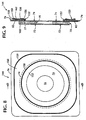
- the ostomy system 140 includes a pouch 142 identical to the pouch 12 and a mounting wafer 144.
- the mounting wafer 144 ( Figs. 8 and 9 ) includes the adhesive disc 70 sandwiched between the silicone release paper 72 and the first landing zone film layer 74, the fabric collar 76 adhered to the first landing zone film layer 74.
- the silicone release collar 82 with a second landing zone film layer 150 joined to the fabric collar 76, and a security film 152 joined to the first and second landing zone film layers 74 and 150.
- the second landing zone film layer 150 is formed of the same material as the second landing zone film layer 102 of the mounting wafer 14 and is also of generally rectangular shape with a width across flats of approximately 3 3 ⁇ 4 inches by 3 3 ⁇ 4 inches (9,5 cm by 9,5 cm).
- the second landing zone film layer 150 differs from the corresponding layer 102 of the mounting wafer 14 by having a thickness of approximately 18 mils and an inner diameter 156 that aligns with and is of the same magnitude as the inner diameter 77 of the fabric collar 76.
- Easy-to-see indicia borders 158 and 159 are respectively provided proximate the inner diameter 156 and the outer periphery of the second landing zone film layer 150 for the same purpose as the indicia borders 114 and 116 on the mounting wafer 14.
- the second landing zone film layer 150 is joined at or near its inner diameter 156 to the film layer 74 by an annular ultrasonic weld 160 ( Fig. 9 ) having an inner diameter of approximately 2 1/8 inches (5,4 cm) and an outer diameter of approximately 2 3/8 inches (6 ). Under this arrangement the second landing zone film layer 150 forms a radial extension of the landing surface provided by the first landing zone film layer 74. A portion 162 of the second landing zone film layer 150 that extends radially beyond the ultrasonic weld 160 is free from securement to the fabric collar 76 and thus referred to as the floating landing zone 162.
- the security film 152 is a ring of plastic material, preferably formed of the same material as the first landing zone film layer 74.
- the security film 152 has a thickness of approximately 2 mils with an inner diameter of approximately 1 3 ⁇ 4 inches (4,4 cm) and an outer diameter of approximately 2 3/8 inches (6 cm).
- Ultrasonic welds (not shown) provided at or near the inner and outer diameters of the security film 152 join the security film 152 to the first and second landing zone film layers 74 and 150 such that the security film 152 covers the inner diametrical edges 77 and 156 of the fabric collar 76 and the second landing zone film layer 150.
- the security film 152 thus provides a transitional landing surface between the first and second landing zone film layers 74 and 150.
- the body side mounting wafer 144 is joined to the abdominal surface 100 and the pouch 12 is joined to the mounting wafer 144 in a manner similar to that previously described for the ostomy system 110.
- the adhesive surface 62 of the pouch face plate 50 contacts the first and second landing zone film layers 74 and 150 and the security film 152. which provide a releasable surface for the resealable adhesive 62 of the pouch face plate 50.
- Peel off or pull away of the pouch face plate 50 from the mounting wafer 144 is accomplished in a manner similar to that described for the ostomy system 10.
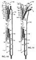
- the face plate 50 is grasped at the tab portion 54 and the mounting wafer 144 is grasped at the floating landing zone 162 as shown in Fig. 11 .
- gripping of the mounting wafer 144 at the floating landing zone 162 by the fingers 124 and 126 help to provide a restraining force on the mounting wafer 144 that is equal and opposite to the pouch peel off force provided by the fingers 128 and 130 on the face plate tab 54.
- Some advantages of the present invention evident from the foregoing description include a low profile repositionable ostomy system with a mounting wafer that has a floating landing zone.
- a further advantage is a manipulable tab portion of the pouch face plate and a manipulable portion of the body-side mounting wafer are manually grippable during pouch removal to help isolate pouch peel off force from the abdominal area underlying the mounting wafer.
- a further advantage is the provision of indicia borders on the mounting wafer to facilitate alignment of the pouch face plate on the mounting wafer.
Landscapes
- Health & Medical Sciences (AREA)
- Epidemiology (AREA)
- Nursing (AREA)
- Orthopedic Medicine & Surgery (AREA)
- Engineering & Computer Science (AREA)
- Biomedical Technology (AREA)
- Heart & Thoracic Surgery (AREA)
- Vascular Medicine (AREA)
- Life Sciences & Earth Sciences (AREA)
- Animal Behavior & Ethology (AREA)
- General Health & Medical Sciences (AREA)
- Public Health (AREA)
- Veterinary Medicine (AREA)
- Orthopedics, Nursing, And Contraception (AREA)
- Revetment (AREA)
- Bag Frames (AREA)
- Control And Other Processes For Unpacking Of Materials (AREA)
- Materials For Medical Uses (AREA)
- Bidet-Like Cleaning Device And Other Flush Toilet Accessories (AREA)
- Catching Or Destruction (AREA)
Claims (11)
- Système (10) d'ostomie comprenant :(a) une poche (12, 142) d'ostomie comprenant une enveloppe (18) de poche formée d'un matériau plastique souple définissant une chambre (46) de collecte de déchets pour des déchets corporels qui traversent une stomie, une ouverture (30) d'entrée des déchets formée dans ladite enveloppe (18) pour un positionnement autour de ladite stomie afin de permettre un passage de matériau de déchets à partir de ladite stomie jusqu'à ladite chambre (46) de collecte, un moyen (50) de couplage de poche adhésive annulaire souple sur ladite enveloppe au niveau de ladite ouverture (30) d'entrée des déchets pour coupler une plaquette (14) de montage côté corps, et(b) une plaquette (14, 144) de montage sur un côté de corps pouvant être raccordée à une surface de corps autour d'une stomie (120), ladite plaquette (14) de montage sur un côté de corps comportant une ouverture (16) pour une stomie (120) et une surface (74, 102) de région de réception non adhésive sur un côté avant de la plaquette de montage pour coupler un engagement dans le moyen (50) de couplage de la poche adhésive annulaire, ladite région de réception non adhésive comprend une première partie (74) qui est fixe par rapport à une surface de corps autour d'une stomie (120) quand ladite plaquette (14) de montage est fixée à ladite surface du corps, et une deuxième partie (102, 150) qui peut dévier loin de ladite surface du corps quand ladite plaquette (14) de montage est fixée à ladite surface du corps et dans lequel le moyen (50) de couplage de la poche est couplé contre la première et la deuxième parties de la région (74, 102) de réception non adhésive quand la poche (12, 142) et la plaquette (14, 144) sont couplées, et ladite région de réception non adhésive a un premier bord périphérique exposé, possédant une périphérie prédéterminée et sensiblement la périphérie entière de ladite région de réception non adhésive au niveau dudit premier bord périphérique exposé pouvant être déviée loin de ladite surface du corps, la périphérie étant en général rectangulaire avec des coins arrondis et la deuxième partie de déviation de ladite région de réception non adhésive s'étendant vers l'intérieur à partir dudit premier bord périphérique exposé jusqu'à une bordure en général circulaire dans les limites dudit premier bord périphérique exposé et ladite deuxième partie de déviation (102, 150) de ladite région de réception non adhésive (102, 150) est prévue au niveau dudit premier bord périphérique exposé pour permettre une préhension manuelle de ladite plaquette (14, 144) de montage au niveau dudit premier bord périphérique exposé quand ladite poche (12) est détachée d'une position couplée avec ladite plaquette (14, 144) de montage.
- Système d'ostomie selon la revendication 1, dans lequel ladite région de réception non adhésive comprend une première et une deuxième sections distinctes comportant des périphéries interne et externe, et lesdites première et deuxième sections distinctes sont taillées de telle manière que ladite première section se superpose sur la périphérie externe de ladite deuxième section, et le premier bord périphérique exposé est au niveau de la périphérie externe de ladite première section.
- Système d'ostomie selon la revendication 2, dans lequel une première ligne de séparation d'indications est fournie pour voir au niveau de ladite région de réception non adhésive proche dudit premier bord périphérique exposé.
- Système d'ostomie selon la revendication 3, dans lequel la périphérie interne de ladite deuxième section distincte est constituée d'une intensité moins importante que la périphérie interne de ladite première section et une deuxième ligne (114, 158) de séparation d'indications est fournie pour voir au niveau de ladite région de réception non adhésive entre la périphérie interne de ladite deuxième section (106) et la périphérie externe de ladite première section.
- Système d'ostomie selon la revendication 4, dans lequel la deuxième ligne (114, 158) de séparation d'indices est fournie pour voir au niveau de la région de réception non adhésive proche de la périphérie interne de ladite première section.
- Système d'ostomie selon la revendication 2, dans lequel ladite section (102, 150) annulaire intermédiaire se superpose sur une première partie (74) de ladite première section et une deuxième partie de ladite deuxième section de ladite région de réception non adhésive.
- Système d'ostomie selon la revendication 6, dans lequel ladite section (102, 150) annulaire intermédiaire possède une surface (104) non adhésive exposée qui constitue une partie de ladite surface de région de réception non adhésive.
- Système d'ostomie selon la revendication 2, dans lequel ladite deuxième section (104) de ladite région de réception non adhésive s'étend radialement au-delà de ladite première section de ladite région de réception non adhésive et ladite plaquette (14, 144) de montage comprend en outre une partie (76) de tissu intercalée entre la première et la deuxième sections de ladite région de réception non adhésive, ladite partie (76) de tissu s'étendant radialement au-delà des dites première et deuxième sections de région de réception non adhésive.
- Système d'ostomie selon la revendication 8, dans lequel ladite deuxième partie de déviation de ladite région de réception non adhésive se confronte à ladite partie (76) de tissu.
- Système d'ostomie selon la revendication 9, dans lequel ladite partie (76) de tissu possède une périphérie externe qui s'étend au-delà du premier bord périphérique exposé de ladite région (74) de réception non adhésive.
- Système d'ostomie selon la revendication 1, dans lequel ledit moyen (50) de couplage de poche possède une périphérie en général circulaire et l'onglet (54) de manipulation s'étend à partir de ladite périphérie en général circulaire pour faciliter la manipulation et le positionnement dudit moyen de couplage de poche autour de la stomie (120).
Priority Applications (2)
| Application Number | Priority Date | Filing Date | Title |
|---|---|---|---|
| EP07014864.8A EP1852094B1 (fr) | 1997-11-20 | 1998-11-18 | Poche repositionnable dotée d'une zone de réception mobile |
| DK07014864.8T DK1852094T3 (da) | 1998-11-18 | 1998-11-18 | Genpositionerbar pose med flydende forbindelseszone |
Applications Claiming Priority (3)
| Application Number | Priority Date | Filing Date | Title |
|---|---|---|---|
| US6627697P | 1997-11-20 | 1997-11-20 | |
| US66276P | 1997-11-20 | ||
| PCT/US1998/024642 WO1999026565A1 (fr) | 1997-11-20 | 1998-11-18 | Poche a repositionnement dotee d'une zone de reception mobile |
Related Child Applications (2)
| Application Number | Title | Priority Date | Filing Date |
|---|---|---|---|
| EP07014864.8A Division EP1852094B1 (fr) | 1997-11-20 | 1998-11-18 | Poche repositionnable dotée d'une zone de réception mobile |
| EP07014864.8 Division-Into | 2007-07-30 |
Publications (4)
| Publication Number | Publication Date |
|---|---|
| EP1033952A1 EP1033952A1 (fr) | 2000-09-13 |
| EP1033952A4 EP1033952A4 (fr) | 2001-12-12 |
| EP1033952B1 EP1033952B1 (fr) | 2007-10-24 |
| EP1033952B2 true EP1033952B2 (fr) | 2013-10-02 |
Family
ID=22068459
Family Applications (1)
| Application Number | Title | Priority Date | Filing Date |
|---|---|---|---|
| EP98958640.9A Expired - Lifetime EP1033952B2 (fr) | 1997-11-20 | 1998-11-18 | Poche a repositionnement dotee d'une zone de reception mobile |
Country Status (10)
| Country | Link |
|---|---|
| US (1) | US8439883B1 (fr) |
| EP (1) | EP1033952B2 (fr) |
| JP (2) | JP4571303B2 (fr) |
| AT (1) | ATE376407T1 (fr) |
| AU (1) | AU760036B2 (fr) |
| CA (1) | CA2309729C (fr) |
| DE (1) | DE69838619T2 (fr) |
| DK (1) | DK1033952T4 (fr) |
| ES (1) | ES2294824T3 (fr) |
| WO (1) | WO1999026565A1 (fr) |
Families Citing this family (31)
| Publication number | Priority date | Publication date | Assignee | Title |
|---|---|---|---|---|
| AU2001258225B2 (en) * | 2000-05-08 | 2005-01-27 | Coloplast A/S | Ostomy carrier device with flexible flange |
| EP1269946A1 (fr) * | 2001-06-11 | 2003-01-02 | The Procter & Gamble Company | Forme améliorée d'une poche collectrice pour déchets humains |
| DK176264B1 (da) * | 2003-03-27 | 2007-05-07 | Coloplast As | Stomiindretning |
| US20050080155A1 (en) * | 2003-10-14 | 2005-04-14 | Fattman George F. | Ostomy pouch attachment adhesives resistant to stomal effluent |
| SE0500062A0 (sv) | 2005-01-11 | 2006-07-12 | Moelnlycke Health Care Ab | Komponent för att underlätta infästning av ett stomibandage mot hud |
| EP2246015A1 (fr) * | 2009-05-01 | 2010-11-03 | Hollister Incorporated | Système de couplage d'appareillage stomique et appareillage stomique |
| US8211073B2 (en) | 2009-06-17 | 2012-07-03 | Hollister Incorporated | Ostomy faceplate having moldable adhesive wafer with diminishing surface undulations |
| JP6058661B2 (ja) * | 2011-07-28 | 2017-01-11 | ホリスター・インコーポレイテッドHollister Incorporated | オストミーシーリング部材パッケージ、及びオストミーシーリング部材 |
| EP2928421B1 (fr) | 2012-12-06 | 2017-05-31 | Coloplast A/S | Plaque de base de stomie adaptable |
| WO2015048446A1 (fr) * | 2013-09-26 | 2015-04-02 | 3 West C, Llc | Sac de stomie |
| EP3270835B1 (fr) | 2015-03-16 | 2019-05-08 | Coloplast A/S | Dispositif de stomie |
| GB2553096B (en) * | 2016-08-18 | 2022-02-16 | Welland Medical Ltd | Flange extender having removal tab |
| US9750633B1 (en) * | 2016-08-25 | 2017-09-05 | Arthur J Follenius | Waterproof cover for an ostomy pouch |
| EP3912602B1 (fr) * | 2017-04-10 | 2024-08-21 | Coloplast A/S | Élément latéral du corps d'un appareil pour stomie |
| US11534326B2 (en) * | 2017-04-10 | 2022-12-27 | Coloplast A/S | Body side member of an ostomy appliance |
| EP3609443B1 (fr) * | 2017-04-10 | 2023-10-25 | Coloplast A/S | Élément côté corps d'un appareil de stomie |
| EP4180010A1 (fr) | 2017-12-22 | 2023-05-17 | Coloplast A/S | Partie d'ensemble capteur d'un système de stomie ayant un capteur d'humidité |
| JP7472022B2 (ja) | 2017-12-22 | 2024-04-22 | コロプラスト アクティーゼルスカブ | オストミー装具のためのベースプレート、モニタデバイス及びオストミー装具のためのシステム |
| US11865029B2 (en) | 2017-12-22 | 2024-01-09 | Coloplast A/S | Monitor device of a medical system having a connector for coupling to both a base plate and an accessory device |
| AU2018386861B2 (en) | 2017-12-22 | 2024-03-14 | Coloplast A/S | Ostomy appliance with angular leakage detection |
| WO2019120452A1 (fr) | 2017-12-22 | 2019-06-27 | Coloplast A/S | Pièce d'accouplement dotée d'une charnière pour une plaque de base de stomie et partie d'assemblage de capteur |
| WO2019120445A1 (fr) | 2017-12-22 | 2019-06-27 | Coloplast A/S | Plaque de base et ensemble capteur d'un système de stomie doté d'un capteur de fuite |
| EP4032510B1 (fr) | 2017-12-22 | 2025-07-09 | Coloplast A/S | Plaque de base avec points de capteur sélectifs et méthode de fabrication |
| CN111885984B (zh) | 2018-03-15 | 2023-08-04 | 科洛普拉斯特公司 | 基于传感器数据来确定造口术器具穿戴时间的设备和方法 |
| USD1012280S1 (en) * | 2018-11-30 | 2024-01-23 | B. Braun Medical Sas | Ostomy device assembly |
| AU2020214965B2 (en) * | 2019-01-31 | 2025-09-18 | Coloplast A/S | A sensor patch for an ostomy appliance |
| KR102807748B1 (ko) | 2019-01-31 | 2025-05-14 | 컬러플라스트 에이/에스 | 스토마용 센서 패치 |
| US12232998B2 (en) | 2019-01-31 | 2025-02-25 | Coloplast A/S | Application of a stomal sensor patch |
| EP3930642B1 (fr) * | 2019-02-28 | 2023-10-25 | Coloplast A/S | Patch de capteur destiné à être fixé à une plaque de base |
| EP3958801B1 (fr) | 2019-04-26 | 2024-08-21 | Coloplast A/S | Patch de capteur destiné à être fixé à une plaque de base |
| US20260124065A1 (en) * | 2024-11-03 | 2026-05-07 | Adam’s Ostomy Pocket, LLC | Ostomy pocket patch |
Citations (14)
| Publication number | Priority date | Publication date | Assignee | Title |
|---|---|---|---|---|
| US3804091A (en) † | 1972-09-18 | 1974-04-16 | Hollister Inc | Ostomy appliance |
| US4419100A (en) † | 1982-03-16 | 1983-12-06 | Hollister Incorporated | Ostomy appliance and faceplate attachment therefor |
| WO1991001702A1 (fr) † | 1989-08-02 | 1991-02-21 | Marna Broida | Tampon absorbant pour usage medical |
| US5160330A (en) † | 1990-09-15 | 1992-11-03 | Smiths Industries Public Limited Company | Medico-surgical collection bag assemblies |
| US5250043A (en) † | 1989-08-16 | 1993-10-05 | Castellana Frank S | Continent ostomate bandage |
| US5257981A (en) † | 1990-06-04 | 1993-11-02 | Alcare Co. Ltd. | Ostomy appliance |
| US5356399A (en) † | 1991-02-15 | 1994-10-18 | Alcare Col, Ltd. | Ostomy appliance |
| US5384174A (en) † | 1988-05-21 | 1995-01-24 | Smith & Nephew Plc | Adhesive sheet |
| US5423783A (en) † | 1991-09-30 | 1995-06-13 | Minnesota Mining And Manufacturing Company | Ostomy bag with elastic and heat sealable medical tapes |
| US5429626A (en) † | 1994-03-14 | 1995-07-04 | Fenton; Leonard | Ostomy pouch mounting arrangement |
| US5468235A (en) † | 1995-03-06 | 1995-11-21 | Hollister Incorporated | Ostomy pouch and filter assembly with successive flap vents |
| WO1996038106A1 (fr) † | 1995-05-29 | 1996-12-05 | Coloplast A/S | Systeme de collecte de selles |
| EP0793951A1 (fr) † | 1996-02-29 | 1997-09-10 | Bristol-Myers Squibb Company | Système d'ostomie à profil bas avec poche repositionnable |
| EP0998247B1 (fr) † | 1996-10-22 | 2006-03-22 | Coloplast A/S | Dispositif d'ostomie |
Family Cites Families (11)
| Publication number | Priority date | Publication date | Assignee | Title |
|---|---|---|---|---|
| GB8430031D0 (en) * | 1983-12-19 | 1985-01-09 | Craig Med Prod Ltd | Ostomy appliance |
| US4894058A (en) * | 1986-10-08 | 1990-01-16 | E. R. Squibb & Sons, Inc. | Adhesive connecting rings for an ostomy device |
| US5074852A (en) * | 1989-08-16 | 1991-12-24 | E. R. Squibb & Sons, Inc. | Occlusive attaching device for ostomy appliance |
| US5346482A (en) * | 1993-04-02 | 1994-09-13 | Hollister Incorporated | Two-piece ostomy appliance having flushable pouch and faceplate with protective collar |
| DK75993D0 (da) * | 1993-06-25 | 1993-06-25 | Ole Jensen | A ostomy appliance comprising a flexible pouch and a faceplate, a flexible pouch of an ostomy appliance, and a faceplate of an ostomy appliance |
| JPH07192318A (ja) * | 1993-12-28 | 1995-07-28 | Sony Corp | ディスク記録媒体およびその記録再生装置 |
| US5403299A (en) * | 1994-01-18 | 1995-04-04 | Hollister Incorporated | Flush-interval indicator for soluble pouches |
| US5496296A (en) * | 1994-06-06 | 1996-03-05 | Dansac A/S | Ostomy appliance with extrudable gasket |
| JPH0994299A (ja) | 1995-07-26 | 1997-04-08 | Nitto Denko Corp | カテーテル取付け具およびそれを用いたカテーテルの取付け方法 |
| JPH10192318A (ja) | 1996-12-27 | 1998-07-28 | Alcare Co Ltd | スト−マ装具及び嵌合式医療用具 |
| US6764774B2 (en) * | 2002-06-19 | 2004-07-20 | International Business Machines Corporation | Structures with improved adhesion to Si and C containing dielectrics and method for preparing the same |
-
1998
- 1998-11-18 ES ES98958640T patent/ES2294824T3/es not_active Expired - Lifetime
- 1998-11-18 WO PCT/US1998/024642 patent/WO1999026565A1/fr not_active Ceased
- 1998-11-18 AT AT98958640T patent/ATE376407T1/de active
- 1998-11-18 CA CA002309729A patent/CA2309729C/fr not_active Expired - Fee Related
- 1998-11-18 AU AU14639/99A patent/AU760036B2/en not_active Ceased
- 1998-11-18 DK DK98958640.9T patent/DK1033952T4/da active
- 1998-11-18 DE DE69838619T patent/DE69838619T2/de not_active Expired - Lifetime
- 1998-11-18 JP JP2000521771A patent/JP4571303B2/ja not_active Expired - Lifetime
- 1998-11-18 EP EP98958640.9A patent/EP1033952B2/fr not_active Expired - Lifetime
- 1998-11-19 US US09/196,071 patent/US8439883B1/en not_active Expired - Fee Related
-
2008
- 2008-05-26 JP JP2008136601A patent/JP2008207004A/ja active Pending
Patent Citations (15)
| Publication number | Priority date | Publication date | Assignee | Title |
|---|---|---|---|---|
| US3804091A (en) † | 1972-09-18 | 1974-04-16 | Hollister Inc | Ostomy appliance |
| US4419100A (en) † | 1982-03-16 | 1983-12-06 | Hollister Incorporated | Ostomy appliance and faceplate attachment therefor |
| US5384174A (en) † | 1988-05-21 | 1995-01-24 | Smith & Nephew Plc | Adhesive sheet |
| WO1991001702A1 (fr) † | 1989-08-02 | 1991-02-21 | Marna Broida | Tampon absorbant pour usage medical |
| US5250043A (en) † | 1989-08-16 | 1993-10-05 | Castellana Frank S | Continent ostomate bandage |
| US5257981A (en) † | 1990-06-04 | 1993-11-02 | Alcare Co. Ltd. | Ostomy appliance |
| US5160330A (en) † | 1990-09-15 | 1992-11-03 | Smiths Industries Public Limited Company | Medico-surgical collection bag assemblies |
| EP0476847B1 (fr) † | 1990-09-15 | 1994-11-30 | Smiths Industries Public Limited Company | Assemblages de sac collecteur médico-chirurgical |
| US5356399A (en) † | 1991-02-15 | 1994-10-18 | Alcare Col, Ltd. | Ostomy appliance |
| US5423783A (en) † | 1991-09-30 | 1995-06-13 | Minnesota Mining And Manufacturing Company | Ostomy bag with elastic and heat sealable medical tapes |
| US5429626A (en) † | 1994-03-14 | 1995-07-04 | Fenton; Leonard | Ostomy pouch mounting arrangement |
| US5468235A (en) † | 1995-03-06 | 1995-11-21 | Hollister Incorporated | Ostomy pouch and filter assembly with successive flap vents |
| WO1996038106A1 (fr) † | 1995-05-29 | 1996-12-05 | Coloplast A/S | Systeme de collecte de selles |
| EP0793951A1 (fr) † | 1996-02-29 | 1997-09-10 | Bristol-Myers Squibb Company | Système d'ostomie à profil bas avec poche repositionnable |
| EP0998247B1 (fr) † | 1996-10-22 | 2006-03-22 | Coloplast A/S | Dispositif d'ostomie |
Also Published As
| Publication number | Publication date |
|---|---|
| CA2309729C (fr) | 2008-02-12 |
| DK1033952T3 (da) | 2008-02-11 |
| AU760036B2 (en) | 2003-05-08 |
| JP4571303B2 (ja) | 2010-10-27 |
| US8439883B1 (en) | 2013-05-14 |
| DE69838619T2 (de) | 2008-03-06 |
| EP1033952A1 (fr) | 2000-09-13 |
| DK1033952T4 (da) | 2014-01-13 |
| EP1033952B1 (fr) | 2007-10-24 |
| ATE376407T1 (de) | 2007-11-15 |
| JP2001523517A (ja) | 2001-11-27 |
| DE69838619D1 (de) | 2007-12-06 |
| ES2294824T3 (es) | 2008-04-01 |
| CA2309729A1 (fr) | 1999-06-03 |
| EP1033952A4 (fr) | 2001-12-12 |
| AU1463999A (en) | 1999-06-15 |
| JP2008207004A (ja) | 2008-09-11 |
| WO1999026565A1 (fr) | 1999-06-03 |
Similar Documents
| Publication | Publication Date | Title |
|---|---|---|
| EP1033952B1 (fr) | Poche a repositionnement dotee d'une zone de reception mobile | |
| EP0793951B2 (fr) | Système d'ostomie à profil bas avec poche repositionnable | |
| US5153040A (en) | Wound dressing | |
| AU688463B2 (en) | A tube restraint and a method of making same | |
| EP0371808B1 (fr) | Pansement pour blessures | |
| US4744355A (en) | Hinged end wound dressing | |
| US5491844A (en) | Disposable bib assembly and method of packaging | |
| AU2552192A (en) | An adapter for use in connection with ostomy equipment | |
| US7104974B2 (en) | Ostomy system with repositionable pouch | |
| EP1852094B1 (fr) | Poche repositionnable dotée d'une zone de réception mobile | |
| AU2003213462B2 (en) | Repositionable pouch with floating landing zone | |
| GB2049758A (en) | Disposable Toilet Seat Covers | |
| JPH09238975A (ja) | 粘着フィルム | |
| MXPA00004824A (en) | Repositionable pouch with floating landing zone | |
| JPH071871A (ja) | 隠蔽用シート |
Legal Events
| Date | Code | Title | Description |
|---|---|---|---|
| PUAI | Public reference made under article 153(3) epc to a published international application that has entered the european phase |
Free format text: ORIGINAL CODE: 0009012 |
|
| 17P | Request for examination filed |
Effective date: 20000620 |
|
| AK | Designated contracting states |
Kind code of ref document: A1 Designated state(s): AT BE CH DE DK ES FI FR GB IE IT LI MC NL PT SE |
|
| A4 | Supplementary search report drawn up and despatched |
Effective date: 20011029 |
|
| AK | Designated contracting states |
Kind code of ref document: A4 Designated state(s): AT BE CH DE DK ES FI FR GB IE IT LI MC NL PT SE |
|
| RIC1 | Information provided on ipc code assigned before grant |
Free format text: 7A 61F 5/44 A, 7A 61F 5/448 B, 7A 61F 5/443 B |
|
| 17Q | First examination report despatched |
Effective date: 20050503 |
|
| GRAP | Despatch of communication of intention to grant a patent |
Free format text: ORIGINAL CODE: EPIDOSNIGR1 |
|
| RBV | Designated contracting states (corrected) |
Designated state(s): AT BE CH DE DK ES FI FR GB IE IT LI NL PT SE |
|
| GRAS | Grant fee paid |
Free format text: ORIGINAL CODE: EPIDOSNIGR3 |
|
| GRAA | (expected) grant |
Free format text: ORIGINAL CODE: 0009210 |
|
| AK | Designated contracting states |
Kind code of ref document: B1 Designated state(s): AT BE CH DE DK ES FI FR GB IE IT LI NL PT SE |
|
| REG | Reference to a national code |
Ref country code: GB Ref legal event code: FG4D |
|
| REG | Reference to a national code |
Ref country code: CH Ref legal event code: EP |
|
| REG | Reference to a national code |
Ref country code: IE Ref legal event code: FG4D |
|
| REF | Corresponds to: |
Ref document number: 69838619 Country of ref document: DE Date of ref document: 20071206 Kind code of ref document: P |
|
| REG | Reference to a national code |
Ref country code: CH Ref legal event code: NV Representative=s name: NOVAGRAAF INTERNATIONAL SA |
|
| REG | Reference to a national code |
Ref country code: SE Ref legal event code: TRGR |
|
| REG | Reference to a national code |
Ref country code: DK Ref legal event code: T3 |
|
| ET | Fr: translation filed | ||
| REG | Reference to a national code |
Ref country code: ES Ref legal event code: FG2A Ref document number: 2294824 Country of ref document: ES Kind code of ref document: T3 |
|
| PG25 | Lapsed in a contracting state [announced via postgrant information from national office to epo] |
Ref country code: PT Free format text: LAPSE BECAUSE OF FAILURE TO SUBMIT A TRANSLATION OF THE DESCRIPTION OR TO PAY THE FEE WITHIN THE PRESCRIBED TIME-LIMIT Effective date: 20080324 |
|
| PLBI | Opposition filed |
Free format text: ORIGINAL CODE: 0009260 |
|
| 26 | Opposition filed |
Opponent name: HOLLISTER INCORPORATED Effective date: 20080721 Opponent name: COLOPLAST A/S Effective date: 20080716 |
|
| PLAX | Notice of opposition and request to file observation + time limit sent |
Free format text: ORIGINAL CODE: EPIDOSNOBS2 |
|
| NLR1 | Nl: opposition has been filed with the epo |
Opponent name: HOLLISTER INCORPORATED Opponent name: COLOPLAST A/S |
|
| REG | Reference to a national code |
Ref country code: GB Ref legal event code: 732E |
|
| PLAF | Information modified related to communication of a notice of opposition and request to file observations + time limit |
Free format text: ORIGINAL CODE: EPIDOSCOBS2 |
|
| PG25 | Lapsed in a contracting state [announced via postgrant information from national office to epo] |
Ref country code: FI Free format text: LAPSE BECAUSE OF FAILURE TO SUBMIT A TRANSLATION OF THE DESCRIPTION OR TO PAY THE FEE WITHIN THE PRESCRIBED TIME-LIMIT Effective date: 20071024 |
|
| PLBB | Reply of patent proprietor to notice(s) of opposition received |
Free format text: ORIGINAL CODE: EPIDOSNOBS3 |
|
| BECA | Be: change of holder's address |
Owner name: CONVATEC TECHNOLOGIES INC.6100 NEIL ROAD, SUITE 50 Effective date: 20090302 |
|
| BECH | Be: change of holder |
Owner name: CONVATEC TECHNOLOGIES INC.6100 NEIL ROAD, SUITE 50 Effective date: 20090302 |
|
| REG | Reference to a national code |
Ref country code: CH Ref legal event code: PUE Owner name: CONVATEC TECHNOLOGIES INC. Free format text: BRISTOL-MYERS SQUIBB COMPANY#100 HEADQUARTERS PARK DRIVE#SKILLMAN, NJ 08558 (US) -TRANSFER TO- CONVATEC TECHNOLOGIES INC.#3993 HOWARD HUGHES PARKWAY SUITE 250#LAS VEGAS, NV 89169-6754 (US) |
|
| APBM | Appeal reference recorded |
Free format text: ORIGINAL CODE: EPIDOSNREFNO |
|
| APBP | Date of receipt of notice of appeal recorded |
Free format text: ORIGINAL CODE: EPIDOSNNOA2O |
|
| APAH | Appeal reference modified |
Free format text: ORIGINAL CODE: EPIDOSCREFNO |
|
| APBM | Appeal reference recorded |
Free format text: ORIGINAL CODE: EPIDOSNREFNO |
|
| APBP | Date of receipt of notice of appeal recorded |
Free format text: ORIGINAL CODE: EPIDOSNNOA2O |
|
| APAW | Appeal reference deleted |
Free format text: ORIGINAL CODE: EPIDOSDREFNO |
|
| APAY | Date of receipt of notice of appeal deleted |
Free format text: ORIGINAL CODE: EPIDOSDNOA2O |
|
| APBM | Appeal reference recorded |
Free format text: ORIGINAL CODE: EPIDOSNREFNO |
|
| APBP | Date of receipt of notice of appeal recorded |
Free format text: ORIGINAL CODE: EPIDOSNNOA2O |
|
| REG | Reference to a national code |
Ref country code: NL Ref legal event code: SD Effective date: 20100303 |
|
| APBQ | Date of receipt of statement of grounds of appeal recorded |
Free format text: ORIGINAL CODE: EPIDOSNNOA3O |
|
| REG | Reference to a national code |
Ref country code: FR Ref legal event code: TP |
|
| APAH | Appeal reference modified |
Free format text: ORIGINAL CODE: EPIDOSCREFNO |
|
| REG | Reference to a national code |
Ref country code: CH Ref legal event code: NV Representative=s name: BOVARD AG |
|
| APBU | Appeal procedure closed |
Free format text: ORIGINAL CODE: EPIDOSNNOA9O |
|
| PUAH | Patent maintained in amended form |
Free format text: ORIGINAL CODE: 0009272 |
|
| STAA | Information on the status of an ep patent application or granted ep patent |
Free format text: STATUS: PATENT MAINTAINED AS AMENDED |
|
| 27A | Patent maintained in amended form |
Effective date: 20131002 |
|
| AK | Designated contracting states |
Kind code of ref document: B2 Designated state(s): AT BE CH DE DK ES FI FR GB IE IT LI NL PT SE |
|
| REG | Reference to a national code |
Ref country code: CH Ref legal event code: AELC |
|
| REG | Reference to a national code |
Ref country code: DE Ref legal event code: R102 Ref document number: 69838619 Country of ref document: DE Effective date: 20131002 |
|
| REG | Reference to a national code |
Ref country code: NL Ref legal event code: T3 |
|
| REG | Reference to a national code |
Ref country code: DK Ref legal event code: T4 Effective date: 20140110 |
|
| REG | Reference to a national code |
Ref country code: SE Ref legal event code: RPEO |
|
| PGFP | Annual fee paid to national office [announced via postgrant information from national office to epo] |
Ref country code: AT Payment date: 20131028 Year of fee payment: 16 |
|
| REG | Reference to a national code |
Ref country code: AT Ref legal event code: MK05 Ref document number: 376407 Country of ref document: AT Kind code of ref document: T Effective date: 20071024 |
|
| REG | Reference to a national code |
Ref country code: DE Ref legal event code: R135 Ref document number: 69838619 Country of ref document: DE Effective date: 20140103 |
|
| PGFP | Annual fee paid to national office [announced via postgrant information from national office to epo] |
Ref country code: ES Payment date: 20131011 Year of fee payment: 16 Ref country code: BE Payment date: 20131113 Year of fee payment: 16 |
|
| PG25 | Lapsed in a contracting state [announced via postgrant information from national office to epo] |
Ref country code: DE Free format text: LAPSE BECAUSE OF FAILURE TO SUBMIT A TRANSLATION OF THE DESCRIPTION OR TO PAY THE FEE WITHIN THE PRESCRIBED TIME-LIMIT Effective date: 20140103 |
|
| PG25 | Lapsed in a contracting state [announced via postgrant information from national office to epo] |
Ref country code: ES Free format text: LAPSE BECAUSE OF FAILURE TO SUBMIT A TRANSLATION OF THE DESCRIPTION OR TO PAY THE FEE WITHIN THE PRESCRIBED TIME-LIMIT Effective date: 20131002 |
|
| PGFP | Annual fee paid to national office [announced via postgrant information from national office to epo] |
Ref country code: IE Payment date: 20141110 Year of fee payment: 17 |
|
| REG | Reference to a national code |
Ref country code: FR Ref legal event code: PLFP Year of fee payment: 18 |
|
| REG | Reference to a national code |
Ref country code: IE Ref legal event code: MM4A |
|
| REG | Reference to a national code |
Ref country code: FR Ref legal event code: PLFP Year of fee payment: 19 |
|
| PG25 | Lapsed in a contracting state [announced via postgrant information from national office to epo] |
Ref country code: IE Free format text: LAPSE BECAUSE OF NON-PAYMENT OF DUE FEES Effective date: 20151118 |
|
| PGFP | Annual fee paid to national office [announced via postgrant information from national office to epo] |
Ref country code: DK Payment date: 20161110 Year of fee payment: 19 Ref country code: CH Payment date: 20161115 Year of fee payment: 19 Ref country code: NL Payment date: 20161110 Year of fee payment: 19 Ref country code: FR Payment date: 20161014 Year of fee payment: 19 Ref country code: GB Payment date: 20161116 Year of fee payment: 19 |
|
| PGFP | Annual fee paid to national office [announced via postgrant information from national office to epo] |
Ref country code: SE Payment date: 20161111 Year of fee payment: 19 |
|
| PG25 | Lapsed in a contracting state [announced via postgrant information from national office to epo] |
Ref country code: BE Free format text: LAPSE BECAUSE OF NON-PAYMENT OF DUE FEES Effective date: 20131002 |
|
| PGFP | Annual fee paid to national office [announced via postgrant information from national office to epo] |
Ref country code: IT Payment date: 20180122 Year of fee payment: 20 |
|
| REG | Reference to a national code |
Ref country code: DK Ref legal event code: EBP Effective date: 20171130 |
|
| REG | Reference to a national code |
Ref country code: SE Ref legal event code: EUG |
|
| REG | Reference to a national code |
Ref country code: NL Ref legal event code: MM Effective date: 20171201 |
|
| GBPC | Gb: european patent ceased through non-payment of renewal fee |
Effective date: 20171118 |
|
| PG25 | Lapsed in a contracting state [announced via postgrant information from national office to epo] |
Ref country code: CH Free format text: LAPSE BECAUSE OF NON-PAYMENT OF DUE FEES Effective date: 20171130 Ref country code: LI Free format text: LAPSE BECAUSE OF NON-PAYMENT OF DUE FEES Effective date: 20171130 |
|
| PG25 | Lapsed in a contracting state [announced via postgrant information from national office to epo] |
Ref country code: SE Free format text: LAPSE BECAUSE OF NON-PAYMENT OF DUE FEES Effective date: 20171119 |
|
| REG | Reference to a national code |
Ref country code: FR Ref legal event code: ST Effective date: 20180731 |
|
| PG25 | Lapsed in a contracting state [announced via postgrant information from national office to epo] |
Ref country code: FR Free format text: LAPSE BECAUSE OF NON-PAYMENT OF DUE FEES Effective date: 20171130 Ref country code: NL Free format text: LAPSE BECAUSE OF NON-PAYMENT OF DUE FEES Effective date: 20171201 |
|
| PG25 | Lapsed in a contracting state [announced via postgrant information from national office to epo] |
Ref country code: GB Free format text: LAPSE BECAUSE OF NON-PAYMENT OF DUE FEES Effective date: 20171118 Ref country code: DK Free format text: LAPSE BECAUSE OF NON-PAYMENT OF DUE FEES Effective date: 20171130 |
|
| PG25 | Lapsed in a contracting state [announced via postgrant information from national office to epo] |
Ref country code: ES Free format text: THE PATENT HAS BEEN ANNULLED BY A DECISION OF A NATIONAL AUTHORITY Effective date: 20131002 |
|
| PGFP | Annual fee paid to national office [announced via postgrant information from national office to epo] |
Ref country code: DE Payment date: 20131113 Year of fee payment: 16 |