EP1035517A2 - Procédé de protection d'un module de sécurité et ensemble pour mettre en oeuvre ledit procédé - Google Patents
Procédé de protection d'un module de sécurité et ensemble pour mettre en oeuvre ledit procédé Download PDFInfo
- Publication number
- EP1035517A2 EP1035517A2 EP00250064A EP00250064A EP1035517A2 EP 1035517 A2 EP1035517 A2 EP 1035517A2 EP 00250064 A EP00250064 A EP 00250064A EP 00250064 A EP00250064 A EP 00250064A EP 1035517 A2 EP1035517 A2 EP 1035517A2
- Authority
- EP
- European Patent Office
- Prior art keywords
- security module
- voltage
- line
- processor
- unit
- Prior art date
- Legal status (The legal status is an assumption and is not a legal conclusion. Google has not performed a legal analysis and makes no representation as to the accuracy of the status listed.)
- Granted
Links
- 238000000034 method Methods 0.000 title claims abstract description 17
- 238000001514 detection method Methods 0.000 claims abstract description 38
- 238000012544 monitoring process Methods 0.000 claims abstract description 32
- 238000009434 installation Methods 0.000 claims abstract description 9
- 230000015654 memory Effects 0.000 claims description 36
- 238000004891 communication Methods 0.000 claims description 11
- 239000003990 capacitor Substances 0.000 claims description 8
- 230000008859 change Effects 0.000 claims description 7
- 230000011664 signaling Effects 0.000 claims description 7
- 230000005540 biological transmission Effects 0.000 claims description 6
- 238000004382 potting Methods 0.000 claims description 6
- 230000003068 static effect Effects 0.000 claims description 6
- 230000001960 triggered effect Effects 0.000 claims description 5
- 150000001875 compounds Chemical class 0.000 claims description 4
- 230000003213 activating effect Effects 0.000 claims description 2
- 230000000903 blocking effect Effects 0.000 claims description 2
- 238000012217 deletion Methods 0.000 claims description 2
- 230000037430 deletion Effects 0.000 claims description 2
- 238000012545 processing Methods 0.000 description 12
- 238000007639 printing Methods 0.000 description 11
- 238000010586 diagram Methods 0.000 description 8
- 230000006870 function Effects 0.000 description 6
- 238000005516 engineering process Methods 0.000 description 5
- 238000003860 storage Methods 0.000 description 5
- 238000007789 sealing Methods 0.000 description 4
- 238000012360 testing method Methods 0.000 description 4
- 238000012546 transfer Methods 0.000 description 4
- 238000013461 design Methods 0.000 description 3
- 238000011156 evaluation Methods 0.000 description 3
- 239000000463 material Substances 0.000 description 3
- 230000002093 peripheral effect Effects 0.000 description 3
- 238000004364 calculation method Methods 0.000 description 2
- 238000004140 cleaning Methods 0.000 description 2
- 230000002950 deficient Effects 0.000 description 2
- 238000012423 maintenance Methods 0.000 description 2
- 230000008569 process Effects 0.000 description 2
- 230000008439 repair process Effects 0.000 description 2
- KSAVQLQVUXSOCR-UHFFFAOYSA-M sodium lauroyl sarcosinate Chemical compound [Na+].CCCCCCCCCCCC(=O)N(C)CC([O-])=O KSAVQLQVUXSOCR-UHFFFAOYSA-M 0.000 description 2
- 238000011144 upstream manufacturing Methods 0.000 description 2
- WHXSMMKQMYFTQS-UHFFFAOYSA-N Lithium Chemical compound [Li] WHXSMMKQMYFTQS-UHFFFAOYSA-N 0.000 description 1
- 101001128814 Pandinus imperator Pandinin-1 Proteins 0.000 description 1
- 230000009471 action Effects 0.000 description 1
- 230000004913 activation Effects 0.000 description 1
- 230000000712 assembly Effects 0.000 description 1
- 238000000429 assembly Methods 0.000 description 1
- 230000004888 barrier function Effects 0.000 description 1
- 230000006399 behavior Effects 0.000 description 1
- 239000003795 chemical substances by application Substances 0.000 description 1
- 239000003086 colorant Substances 0.000 description 1
- 239000004020 conductor Substances 0.000 description 1
- 230000001419 dependent effect Effects 0.000 description 1
- 238000011161 development Methods 0.000 description 1
- 230000018109 developmental process Effects 0.000 description 1
- 238000005538 encapsulation Methods 0.000 description 1
- 238000003780 insertion Methods 0.000 description 1
- 230000037431 insertion Effects 0.000 description 1
- 230000003993 interaction Effects 0.000 description 1
- 238000012432 intermediate storage Methods 0.000 description 1
- 230000001788 irregular Effects 0.000 description 1
- 229910052744 lithium Inorganic materials 0.000 description 1
- 238000005259 measurement Methods 0.000 description 1
- 238000012805 post-processing Methods 0.000 description 1
- 230000005855 radiation Effects 0.000 description 1
- 230000000717 retained effect Effects 0.000 description 1
- 238000000926 separation method Methods 0.000 description 1
- 238000012795 verification Methods 0.000 description 1
Images


Classifications
-
- G—PHYSICS
- G07—CHECKING-DEVICES
- G07B—TICKET-ISSUING APPARATUS; FARE-REGISTERING APPARATUS; FRANKING APPARATUS
- G07B17/00—Franking apparatus
- G07B17/00733—Cryptography or similar special procedures in a franking system
-
- G—PHYSICS
- G07—CHECKING-DEVICES
- G07B—TICKET-ISSUING APPARATUS; FARE-REGISTERING APPARATUS; FRANKING APPARATUS
- G07B17/00—Franking apparatus
- G07B17/00185—Details internally of apparatus in a franking system, e.g. franking machine at customer or apparatus at post office
- G07B17/00193—Constructional details of apparatus in a franking system
- G07B2017/00233—Housing, e.g. lock or hardened casing
-
- G—PHYSICS
- G07—CHECKING-DEVICES
- G07B—TICKET-ISSUING APPARATUS; FARE-REGISTERING APPARATUS; FRANKING APPARATUS
- G07B17/00—Franking apparatus
- G07B17/00185—Details internally of apparatus in a franking system, e.g. franking machine at customer or apparatus at post office
- G07B17/00193—Constructional details of apparatus in a franking system
- G07B2017/00266—Man-machine interface on the apparatus
- G07B2017/00298—Visual, e.g. screens and their layouts
-
- G—PHYSICS
- G07—CHECKING-DEVICES
- G07B—TICKET-ISSUING APPARATUS; FARE-REGISTERING APPARATUS; FRANKING APPARATUS
- G07B17/00—Franking apparatus
- G07B17/00185—Details internally of apparatus in a franking system, e.g. franking machine at customer or apparatus at post office
- G07B17/00193—Constructional details of apparatus in a franking system
- G07B2017/00266—Man-machine interface on the apparatus
- G07B2017/00306—Acoustic, e.g. voice control or speech prompting
-
- G—PHYSICS
- G07—CHECKING-DEVICES
- G07B—TICKET-ISSUING APPARATUS; FARE-REGISTERING APPARATUS; FRANKING APPARATUS
- G07B17/00—Franking apparatus
- G07B17/00185—Details internally of apparatus in a franking system, e.g. franking machine at customer or apparatus at post office
- G07B17/00314—Communication within apparatus, personal computer [PC] system, or server, e.g. between printhead and central unit in a franking machine
- G07B2017/00346—Power handling, e.g. power-down routine
-
- G—PHYSICS
- G07—CHECKING-DEVICES
- G07B—TICKET-ISSUING APPARATUS; FARE-REGISTERING APPARATUS; FRANKING APPARATUS
- G07B17/00—Franking apparatus
- G07B17/00185—Details internally of apparatus in a franking system, e.g. franking machine at customer or apparatus at post office
- G07B17/00362—Calculation or computing within apparatus, e.g. calculation of postage value
- G07B2017/00395—Memory organization
- G07B2017/00403—Memory zones protected from unauthorized reading or writing
-
- G—PHYSICS
- G07—CHECKING-DEVICES
- G07B—TICKET-ISSUING APPARATUS; FARE-REGISTERING APPARATUS; FRANKING APPARATUS
- G07B17/00—Franking apparatus
- G07B17/00733—Cryptography or similar special procedures in a franking system
- G07B2017/00959—Cryptographic modules, e.g. a PC encryption board
- G07B2017/00967—PSD [Postal Security Device] as defined by the USPS [US Postal Service]
Definitions
- the invention relates to a method for protecting a security module, according to the type specified in the preamble of claim 1, and a Arrangement for performing the method, according to the in the preamble of claim 3.
- a postal Security module is especially for use in a Franking machine or mail processing machine or computer with Mail processing function suitable.
- Modern franking machines such as that known from US 4,746,234 Thermal transfer franking machine, set a fully electronic digital Printing device.
- a microprocessor which is surrounded by a secured housing that has an opening for feeding a letter. With a letter feed transmits a mechanical letter sensor (microswitch) Pressure request signal to the microprocessor.
- the franking imprint contains previously entered and stored postal information to carry the letter.
- the control unit of the franking machine performs software billing, exercises a monitoring function possibly with regard to the conditions for a data update and controls the reloading of a port credit.
- a Franking machine for franking mail is with a printer for Printing the postage stamp on the mail, with a control for Control the printing and peripheral components of the Franking machine, with a billing unit for billing Postage, with at least one non-volatile memory for Storage of postage data, with at least one non-volatile Memory for storing safety-relevant data and with one Calendar / clock equipped.
- the non-volatile memory of the safety-relevant Dates and / or the calendar / clock is usually from one Battery powered.
- Known franking machines are security-relevant Data (cryptographic keys, etc.) in non-volatile Save saved. These memories are EEPROM, or FRAM battery-backed SRAM.
- Known franking machines often also have via an internal real time clock (RTC), which is controlled by a Battery is powered.
- RTC real time clock
- potted modules that Integrated circuits and a lithium battery included. These modules after the end of the battery life as a whole exchanged and disposed of. From economic and ecological From a point of view, it is cheaper if only the battery is replaced must become. To do this, however, the safety housing must be opened and then be closed and sealed again because the Security against attempted fraud is essentially based on the secured housing that encloses the entire machine.
- EP 660 269 A2 US 5,671,146
- a postage meter repair that may be necessary is then difficult on site if access to the components is difficult or is restricted.
- the secured housing will be opened in the future the so-called postal security module can be reduced, which the Accessibility to the other components can improve economic It would also be replacing the battery of the security module desirable that they exchange in a relatively simple way leaves. To do this, the battery must be outside the safety zone the franking machine. If the battery terminals though being made accessible from the outside is a possible attacker in the Able to manipulate the battery voltage.
- Known battery powered SRAM and RTC have different operating voltage requirements Conditions. The necessary tension to hold SRAM data is below the required voltage to operate from RTC.
- the RTC stops the time - stored in SRAM cells - And the memory contents of the SRAM are retained. At least one of the security measures, such as long time watchdogs, would then be ineffective on the franking machine side.
- long time Watchdogs understood the following:
- the remote data center gives a time credit or a period, in particular a number of Days, or a certain day before, by which the franking device can report via communication link. After unsuccessful Franking is prevented from expiry of the time credit or the deadline.
- Security modules are from electronic data processing systems already known here.
- Power supply and signal detection means and shielding means includes in the housing.
- the shielding agent consists of encapsulation material and line means to which the power supply and Signal acquisition means are connected. The latter responds to one Change in the line resistance of the line means.
- the safety module contains an internal battery, a voltage switch from system voltage to battery voltage, a power gate and a short-circuit transistor and other sensors. If the If the voltage drops below a certain limit, the power reacts Gate. If the line resistance, the temperature or the radiation the logic reacts.
- the output of the short-circuit transistor is switched to L level, whereby a cryptographic stored in memory Key is deleted.
- the lifespan is non-interchangeable Battery and thus the safety module for use in Franking equipment or mail processing machines too small.
- a larger mail processing machine is, for example, the JetMail®.
- a franking imprint is arranged here by means of a stationary one Inkjet printhead with a non-horizontal approximately vertical Letter transport generated.
- a suitable version for one Printing device has already been proposed in DE 196 05 015 C1.
- the mail processing machine has a meter and a base. Should that Meters can be equipped with a housing, making components lighter accessible, then it must be through a postal security module be protected from attempted fraud, which includes at least billing who carries out postage. To influence the course of the program exclude was already in EP 789 333 A2 under the Title: Postage meter proposed a security module with a Equip user circuit (Application Specific Integrated Circuit) ASIC, which has a hardware accounting unit. The user circuit also controls the print data transfer to the print head.
- Equip user circuit Application Specific Integrated Circuit
- franking machines are also modular built up. This modularity enables the exchange of modules and Components for various reasons. For example, defective Modules exchanged and checked, repaired or new modules be replaced. Because the greatest care when exchanging Assemblies that contain safety-relevant data are required, The exchange usually requires the use of a service Technician and measures taken in the event of improper use or unauthorized replacement of a security module and its functionality prevent. The latter is very complex.
- the invention is based, with little effort the task To ensure protection against an unauthorized manipulated security module, if the security module is arranged interchangeably.
- the Exchange should be possible in the simplest possible way.
- the invention is based on the exchange by means of functional units and use of a security module of a franking machine, Postprocessing device or similar device to determine guarantee the users of the various devices about the correct functioning of the security module and thus of the whole Device.
- An exchange of a security module will at least detected and, if necessary, subsequently signaled as a condition if the safety module is plugged in again and with a system voltage is supplied.
- Changes in the state of the security module are by means of a first functional unit and by means of one Battery powered detection unit detects a resettable Exhibits self-retention.
- the first functional unit can each Evaluate the condition when it is supplied with system voltage again.
- the advantages are a quick reaction to changes in the State of the safety module and low battery power consumption the circuit of the detection unit during the Failure to supply the safety module with the system voltage.
- Reinitialization is intended to be associated with communication by means of a remote data center from the first functional unit is carried out after a dynamic plugged-in detection was successfully carried out during the detection from the first functional unit via a current loop of the interface unit Information is exchanged, its error-free transmission proof of the correct installation of the safety module he brings.
- the activation of functional units of the safety module is done by resetting them.
- the first functional unit is a with processor connected to the other functional units, which programs is to determine the respective state.
- the second functional unit is a voltage monitoring unit with resettable Self-holding and the third functional unit is an unplugged detection circuit with resettable self-holding.
- FIG. 1 shows a block diagram of the security module 100 with the Contact groups 101, 102 for connection to an interface 8 and with the Battery contact terminals 103 and 104 of a battery interface for one Battery 134 shown.
- the security module 100 has a hard potting compound is shed, the battery is 134 of the Security module 100 outside the sealing compound on a circuit board arranged interchangeably.
- the circuit board carries the battery contact terminals 103 and 104 for the connection of the poles of the battery 134.
- the security module 100 is turned on corresponding interface 8 of the main board (motherboard) 9 inserted.
- the first contact group 101 is connected to the system bus of a control device in communication link and the second contact group 102 serves to supply the security module 100 with the system voltage.
- the first and / or second contact group 101 and / or 102 are for static and dynamic monitoring of the connection of the security module 100 trained.
- Via pins P23 and P25 of the contact group 102 is the supply of the security module 100 with the system voltage the main board 9 realized and via the pins P1, P2 and P4 a dynamic and static unplugged detection by the Security module 100 implemented.
- the security module 100 has one in a manner known per se Microprocessor 120 on the integrated - not shown - Read-only memory (internal ROM) with the special application program contains what the post office franking machine does or approved by the respective postal carrier.
- the internal data bus 126 a conventional read-only memory ROM or FLASH memory be connected.
- the safety module 100 has a reset circuit unit in a manner known per se 130, a user circuit ASIC 150 and a Logic PAL 160, which serves as a control signal generator for the ASIC.
- the Reset circuit unit 130 or the user circuit ASIC 150 and the logic PAL 160 and possibly further - not shown - memories are connected via lines 191 and 129 with system voltage Us + supplied by the main board when the franking device is switched on 9 is delivered.
- the essential ones have already been described in EP 789 333 A2 Parts of a postal security module PSM explained that the Implement the functions of accounting and securing the postage fee data.
- the system voltage Us + is also present via a diode 181 and the line 136 at the input of the voltage monitoring unit 12.
- a second operating voltage U b + is supplied at the output of the voltage monitoring unit 12 and is available via the line 138.
- the system voltage Us + is not available, but only the battery voltage Ub +.
- the battery contact terminal 104 located at the negative pole is connected to ground. From the battery contact terminal 103 located at the positive pole, battery voltage is supplied via a line 193, via a second diode 182 and line 136 to the input of the voltage monitoring unit.
- a commercially available circuit can be used as the voltage transformer 180.
- the output of the voltage monitoring unit 12 is connected via a line 138 to an input for this second operating voltage U b + of the processor 120, which leads to at least one RAM memory area 122, 124 and guarantees non-volatile storage there for as long as the second operating voltage U b + in the required amount.
- Processor 120 preferably includes internal RAM 124 and real time clock (RTC) 122.
- the voltage monitoring unit 12 in the security module has one Resettable latching on by processor 120 via a line 164 can be queried and reset via a line 135.
- For the voltage monitoring unit shows a reset of the self-holding 12 Switching means on The reset can only be triggered if the battery voltage has risen above the predetermined threshold.
- the lines 135 and 164 are each with a pin (Pin1 and 2) of the Processor 120 connected.
- Line 164 provides a status signal to the Processor 120 and line 135 provide a control signal to the Voltage monitoring unit 12.
- the line 136 at the input of the voltage monitoring unit 12 also supplies an unplugged detection unit 13 with operating or Battery voltage.
- the unplugged detection unit 13 gives up a status signal from line 139 to a pin 5 of processor 120, which gives a statement about the state of the circuit. From the processor 120 the state of the unplugged detection unit 13 via the Line 139 polled.
- the processor can be used with a pin 4 of the Processor 120 signal issued via line 137 the unplugged detection unit 13 reset. After placing a static connection test carried out. This is done via a line 192 Ground potential queried, which is at connection P4 of interface 8 of the postal security module PSM 100 and can only be queried is when the security module 100 is properly inserted.
- processor 120 There is a line loop on pins 6 and 7 of processor 120, which are connected via pins P1 and P2 of contact group 102 of interface 8 is looped back to processor 120.
- the PSM 100 postal security module is connected to the Motherboard 9 are the processor 120 changing signal levels in very irregular intervals on pins 6, 7 and over looped back the loop.
- the postal security module PSM 100 is equipped with a long-live battery, which also enables monitoring of use without the security module being connected to a system voltage of a mail processing device. Proper use, operation, installation or installation in a suitable environment are such properties to be checked by the functional units of the safety module.
- An initial installation is carried out by the manufacturer of the postal security module. After this initial installation, all that needs to be done is to check first whether the postal security module is separated from its field of application (postal processing facility), this usually taking place during an exchange. This state is monitored by the unplugged detection unit 13. Here, a voltage level is monitored via the ground connection at pin 4 of the interface unit 8. When the functional unit is replaced, this ground connection is interrupted and the unplugged detection unit 13 registers this process as information.
- this information can be evaluated at any time if a restart is desired.
- the regular evaluation of this unplugged signal on line 139 of the unplugged detection unit 13 enables the processor 120 to delete sensitive data, but without changing the billing and customer data in the NVRAM memories.
- the current state of the postal security module with the deleted sensitive data can be understood as a maintenance state, in which the exchange, repair or otherwise is usually carried out. Since the sensitive data of the functional unit is deleted, an error due to improper handling of the postal security module is excluded.
- the sensitive data are, for example, cryptographic keys.
- processor 120 prevents a core functionality of the postal security module, which for example consists in the billing and / or calculation of a security code for the security marking in a security imprint.
- the postal security module PSM is first plugged in and electrically connected to the corresponding interface unit 8 of a mail processing device. The device is then switched on and the postal security module is again supplied with system voltage Us +. Due to the special condition, the proper installation of the postal security module must now be checked again by its functional unit. For this purpose, a second stage of a test (dynamic plug-in detection) is provided. Information is exchanged via an operative connection established between the first functional unit (processor 120) and the current loop 18 of the interface unit 8, the error-free transmission of which provides evidence of correct installation. This is a prerequisite for a successful restart.
- FIG. 2 shows a block diagram of a postage meter machine that uses a chip card read / write unit 70 for reloading change data by chip card and with a printing device 2, which by a Control device 1 is controlled, is equipped.
- the control device 1 has a memory 92 with a microprocessor 91, 93, 94, 95 equipped motherboard 9.
- the program memory 92 contains an operating program for printing at least and at least security-relevant components of the program for a predetermined change in format of part of the useful data.
- the RAM 93 is used for the temporary storage of intermediate results.
- the non-volatile memory NVM 94 is used for the non-volatile temporary storage of data, for example statistical data, which are arranged according to cost centers.
- the calendar / clock module 95 likewise contains addressable but non-volatile memory areas for the non-volatile intermediate storage of intermediate results or also known program parts (for example for the DES algorithm).
- control device 1 is connected to the chip card read / write unit 70, the microprocessor 91 of the control device 1 being programmed, for example, to load the useful data N from the memory area of a chip card 49 for use in corresponding memory areas of the franking machine .
- a first chip card 49 inserted into an insertion slot 72 of the chip card read / write unit 70 allows a data record to be reloaded into the franking machine for at least one application.
- the chip card 49 contains, for example, the postage fees for all the usual postal carrier services in accordance with the tariff of the postal authority and a postal carrier identifier in order to generate a stamp image with the franking machine and to stamp the postal items in accordance with the tariff of the postal authority.
- the control device 1 forms the actual meter with the means 91 to 95 of the aforementioned main board 9 and also includes a keyboard 88, a display unit 89 and an application-specific circuit ASIC 90 and interface 8 for the postal security module PSM 100.
- the safety module PSM 100 is connected to the aforementioned ASIC 90 and the microprocessor 91 and via the parallel ⁇ C bus with at least the means 91 to 95 of the main board 9 and connected to display unit 89.
- the control bus carries cables for the signals CE, RD and WR between the safety module PSM 100 and the aforementioned ASIC 90.
- the microprocessor 91 points preferably a pin for one from the PSM 100 security module issued interrupt signal i, further connections for the keyboard 88, a serial interface SI-1 for the connection of the chip card read / write unit 70 and a serial interface SI-2 for the optional connection of a MODEM to means of the MODEM can for example in the non-volatile memory of the postal Security funds PSM 100 stored credit can be increased.
- the postal security device PSM 100 is secured by a Enclosed housing. Before each franking imprint is made in the postal Security module PSM 100 performed a hardware accounting. Billing takes place independently of cost centers.
- the postal Safety equipment PSM 100 can be designed internally as in the European application EP 789 333 A3 has been described in more detail.
- the ASIC 90 is intended to be a serial interface circuit 98 to a device upstream in the post stream, a serial Interface circuit 96 to the sensors and actuators of the Printing device 2, a serial interface circuit 97 for Print control electronics 16 for the print head 4 and a serial Interface circuit 99 to one of the printing device 20 in the mail stream downstream device.
- DE 197 11 997 is one Design variant for the peripheral interface can be removed, which is suitable for several peripheral devices (stations). It is entitled: Arrangement for communication between a base station and others Stations of a mail processing machine and for its emergency shutdown.
- the interface circuit 96 coupled to the interface circuit 14 located in the machine base provides at least one connection to the sensors 6, 7, 17 and to the actuators, for example to the drive motor 15 for the roller 11 and to a cleaning and sealing station RDS 40 for the ink jet print head 4 , as well as the label provider 50 in the machine base.
- the basic arrangement and the interaction between inkjet print head 4 and the RDS 40 can be found in DE 197 26 642 C2, with the title: Arrangement for positioning an inkjet print head and a cleaning and sealing device.
- One of the sensors 7, 17 arranged in the guide plate 20 is the sensor 17 and is used to prepare for the triggering of pressure when transporting letters.
- the sensor 7 is used to detect the start of a letter for the purpose of triggering pressure when transporting letters.
- the transport device consists of a conveyor belt 10 and two rollers 11, 11 '.
- One of the rollers is the drive roller 11 equipped with a motor 15, another is the idler roller 11 '.
- the drive roller 11 is preferably designed as a toothed roller, and accordingly the conveyor belt 10 is also designed as a toothed belt, which ensures the unambiguous power transmission.
- An encoder 5, 6 is coupled to one of the rollers 11, 11 '.
- the drive roller 11 with an incremental encoder 5 is firmly seated on an axis.
- the incremental encoder 5 is designed, for example, as a slotted disc which interacts with a light barrier 6 and outputs an encoder signal to the main board 9 via the line 19.
- the individual print elements of the print head are connected to print electronics within its housing and that the print head can be controlled for purely electronic printing.
- the print control takes place on the basis of the path control, taking into account the selected stamp offset, which is entered via the keyboard 88 or, if necessary, via a chip card and is stored in the non-volatile memory NVM 94.
- a planned imprint thus results from stamp offset (without printing), the franking print image and, if necessary, further print images for advertising slogan, shipping information (optional prints) and additional editable messages.
- the NVM 94 non-volatile memory has a plurality of memory areas. These include those that save the loaded postage fee tables in a non-volatile manner.
- the chip card read / write unit 70 consists of an associated mechanical carrier for the microprocessor card and contacting unit 74. The latter allows the chip card to be securely mechanically held in the reading position and unambiguously signaled that the reading position of the chip card has been reached in the contacting unit.
- the microprocessor card with the microprocessor 75 has a programmed reading ability for all types of memory cards or chip cards.
- the interface to the franking machine is a serial interface according to the RS232 standard.
- the data transfer rate is min. 1.2 K baud.
- the power supply is switched on by means of a switch 71 connected to the main board. After the power supply is switched on, a self-test function with a readiness message is carried out.
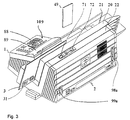
- FIG. 3 is a perspective view of the franking machine from FIG shown at the back.
- the franking machine consists of a meter 1 and a base 2.
- the latter is with a chip card read / write unit 70 equipped, which is arranged behind the guide plate 20 and from the Upper housing edge 22 is accessible.
- a chip card 49 is turned upwards inserted into the slot 72 below.
- the guide plate is in contact with the input data a franking stamp 31 printed.
- the letter feed opening is through a transparent plate 21 and the guide plate 20 laterally limited.
- the Status display of the plugged onto the main board 9 of the meter 1 Security module 100 is visible from the outside through an opening 109.
- FIG. 4 shows a block diagram of the postal security module PSM 100 in a preferred variant.
- the negative pole of the battery 134 is grounded and a pin P23 of the contact group 102.
- the positive pole of the battery 134 is connected via line 193 to one input of voltage changeover switch 180 and line 191 carrying system voltage is connected to the other input of voltage changeover switch 180.
- the SL-389 / P is suitable as a battery 134 for a lifespan of up to 3.5 years or the SL-386 / P for a lifespan of up to 6 years with a maximum power consumption by the PSM 100 commercially available circuit type ADM 8693ARN can be used.
- the output of the voltage changeover switch 180 is connected to the battery monitoring unit 12 and the detection unit 13 via the line 136.
- the battery monitoring unit 12 and the detection unit 13 are in communication with the pins 1, 2, 4 and 5 of the processor 120 via the lines 135, 164 and 137, 139.
- the output of the voltage changeover switch 180 is also present via the line 136 at the supply input of a first memory SRAM, which becomes a non-volatile memory NVRAM of a first technology due to the existing battery 134.
- the security module is connected to the franking machine via the system bus 115, 117, 118.
- Processor 120 can communicate with a remote data center through the system bus and modem 83.
- the billing is performed by the ASIC 150 and checked by the processor 120.
- the postal accounting data are stored in non-volatile memories of different technologies.
- the system voltage is present at the supply input of a second memory NV-RAM 114.
- the latter is a non-volatile memory NVRAM of a second technology, (SHADOW-RAM).
- This second technology preferably comprises a RAM and an EEPROM, the latter automatically taking over the data content in the event of a system power failure.
- the NVRAM 114 of the second technology is connected to the corresponding address and data inputs of the ASIC 150 via an internal address and data bus 112, 113.
- the ASIC 150 contains at least one hardware accounting unit for the Calculation of the postal data to be saved.
- PAL 160 is access logic to the ASIC 150 housed.
- the ASIC 150 is controlled by the PAL 160 logic.
- An address and control bus 117, 115 from the main board 9 is on corresponding pins of the logic PAL 160 and the PAL 160 generates at least one control signal for the ASIC 150 and one Control signal 119 for the program memory FLASH 128.
- the processor 120 executes a program that is stored in the FLASH 128.
- the Processor 120, FLASH 28, ASIC 150 and PAL 160 are one internal system bus interconnected, the lines 110,111,126,119 for data, address and control signals.
- the processor 120 of the security module 100 is via an internal module Data bus 126 with a FLASH 128 and with the ASIC 150 connected.
- the FLASH 128 is supplied with system voltage Us +. He is for example a 128 Kbyte FLASH memory of the type AM29F010-45EC.
- the ASIC 150 of the postal security module 100 delivers an internal address bus 110 addresses 0 to 7 to corresponding address inputs of the FLASH 128.
- the processor 120 of the Security module 100 delivers the via an internal address bus 111 Addresses 8 to 15 to the corresponding address inputs of the FLASH 128.
- the ASIC 150 of the security module 100 is above the Contact group 101 of the interface 8 with the data bus 118, with the Address bus 117 and control bus 115 of the motherboard 9 in Communication link.
- processor 120 has memory 122, 124 on which via line 138 has an operating voltage Ub + of one Voltage monitoring unit 12 is supplied.
- one Real time clock RTC 122 and memory RAM 124 are from one Operating voltage supplied via line 138.
- the voltage monitoring unit (Battery Observer) 12 also provides a status signal 164 and responds to a control signal 135.
- the voltage switch 180 gives as output voltage on line 136 for the Battery Observer 12 and memory 116 that of its input voltages as Supply voltage that is greater than the other.
- the battery 134 of the security module 100 feeds during the idle times the real-time clock in the aforementioned manner outside of normal operation (RTC) 122 with date and / or time registers and / or the static RAM (SRAM) 124, which holds security-relevant data.
- RTC normal operation
- SRAM static RAM
- the tension drops the battery during battery operation below a certain Limit, the voltage monitoring unit 12 becomes the feed point for the RTC and SRAM connected to ground until reset. The voltage on the RTC and SRAM is then 0V.
- Leading the SRAM 124 e.g. important cryptographic keys contains, is deleted very quickly.
- the RESET unit 130 is connected via line 131 to pin 3 of the Processor 120 and connected to a pin of the ASIC's 150.
- the Processor 120 and the ASIC 150 are when the Supply voltage through a reset generation in the RESET unit 130 reset.
- the processor can change the state of the circuit query (status signal) and thus and / or via the evaluation of the Contents of the deleted memory indicate that the Battery voltage has fallen below a certain value in the meantime Has.
- the processor can reset the monitoring circuit, i.e. "make sharp.
- the unplugged detection unit 13 has for measuring the input voltage a line 192 through the connector of the security module and interface 8, preferably via a base on the motherboard 9 the franking machine is connected to ground. This measurement is used for static monitoring of being plugged in and forms the basis for monitoring at a first level. It is envisaged that the Unplugged detection unit 13 circuit means for a resettable Exhibits self-retention, whereby self-retention is triggered, when the voltage level on a measuring voltage line 192 of deviates from a predetermined potential.
- the evaluation logic includes the processor connected to the other functional units 120, which is programmed, the respective state of the security module 100 determine and change. The state of the Latching is via line 139 from processor 120 of the Security module 100 can be queried.
- the measuring voltage potential on the Line 192 corresponds to ground potential when the security module 100 is properly inserted.
- Operating voltage potential is on line 139.
- Ground voltage potential is present on line 139, if the security module 100 is not plugged in.
- the processor 120 points a fifth pin 5, to which line 139 is connected, to query the status of the unplugged detection unit 13 whether it is switched to ground potential with latching. To the state the latching of the unplugged detection unit 13 via the To reset line 137, processor 120 has a fourth pin 4 on.
- a current loop 18 is provided which pins 6 and 7 of the Processor 120 also via the connector of the security module and with each other via the base on the main board 9 of the franking machine connects.
- the lines on pins 6 and 7 of processor 120 are only with a PSM 100 plugged into the main board 9 Current loop 18 closed. This loop forms the basis for dynamic monitoring of the security module being connected on a second level.
- the processor 120 internally has a processing unit CPU 121, one Real time clock RTC 122, a RAM unit 124 and an input / output unit 125 on.
- the processor 120 has at least pins 8, 9 for output a signal for signaling the state of the safety module 100 equipped. I / O ports of the input / output unit are located at pins 8 and 9 125, to which module-internal signaling means are connected, for example colored light emitting diodes LED's 107, 108, which the Signal the status of the safety module 100.
- the security modules can assume various states in their life cycle. So e.g. be detected whether the module is valid cryptographic Contains key. It is also important to differentiate whether that Module works or is defective. The exact type and number of Module states depend on the functions implemented in the module and on the Implementation dependent.
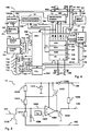
- the circuit diagram of the detection unit 13 is explained. It is provided that the unplugged detection unit 13 has a voltage divider which consists of a series connection of resistors 1310, 1312, 1314 and is connected between a supply voltage potential tapped by a capacitor 1371 and a measuring voltage potential on line 192.
- the circuit is supplied with the system or battery voltage via line 136.
- the respective supply voltage from line 136 reaches the capacitor 1371 of the circuit via a diode 1369.
- a negator 1320, 1398 is located on the output side of the circuit. In the normal state, the transistor 1320 of the negator is blocked and the supply voltage is effective via the resistor 1398 on the line 139, which therefore leads to logic '1', ie H level in the normal state.
- An L level on line 139 is advantageous as a status signal for being unplugged because then no current flows into pin 5 of processor 120, which increases battery life.
- the diode 1369 preferably in conjunction with an electrolytic capacitor 1371, ensures that the circuit upstream of the negator is supplied with a voltage over a relatively long period (> 2 s) at which its function is guaranteed, even though the voltage on line 136 is already was switched off.
- the voltage divider 1310, 1312, 1314 has a tap 1304, to which a capacitor 1306 and the non-inverting input of a comparator 1300 are connected.
- the inverting input of the comparator 1300 is connected to a reference voltage source 1302.
- the output of the comparator 1300 is connected on the one hand via the negator 1324, 1398 to the line 139 and on the other hand to the control input of a switching means 1322 for the self-holding.
- the switching means 1322 is connected in parallel to the resistor 1310 of the voltage divider and the switching means 1316 for resetting the latching is connected between the tap 1304 and ground.
- the tap 1304 of the voltage divider lies at the connection point of the resistors 1312 and 1314.
- the capacitor 1306 connected between the tap 1304 and ground prevents vibrations.
- the voltage at tap 1304 of the voltage divider is compared in comparator 1300 with the reference voltage of source 1302.
- the comparator output remains at L level and transistor 1320 of the negator is blocked.
- line 139 now receives the operating voltage potential and the status signal is logically '1'.
- the voltage divider is dimensioned such that, at ground potential on line 192, tap 1304 carries a voltage which is safely below the switching threshold of comparator 1300. If the connection is interrupted and the line 192 is no longer connected to ground because the security module 100 has been detached from the base on the main board 9 or interface unit 8 of the franking machine, the voltage at the tap 1304 is drawn via the voltage of the reference voltage source 1302 and the Comparator 1300 switches.
- the comparator output is switched to H level and consequently transistor 1320 is switched on.
- line 139 is connected to ground potential and the status signal is logically '0'.
- a transistor 1322 which is connected in parallel with the resistor 1310 of the voltage divider, a self-holding circuit of the unplugged detection unit 13 is realized.
- the control input of transistor 1322 is switched to H level by the comparator output.
- the transistor 1322 turns on and bridges the resistor 1310.
- the voltage divider is only formed by the resistors 1312 and 1314.
- the switchover threshold is increased to such an extent that the comparator also remains in the switched state when the line 192 is again at ground potential because the safety module has been plugged in again.
- the state of the circuit can be queried by the processor 120 via the signal on line 139.
- the unplugged detection unit 13 has a line 137 as a switching means and a switching means 1316 for resetting the latching, the resetting being able to be triggered by the processor 120 via a signal on the line 137.
- the processor 120 can contact a remote data center at any time via a user circuit ASIC 150, a first contact group 101, a system bus of the control device 1 and, for example, the microprocessor 91 via modem 83, which checks the accounting data and, if necessary, further data to the Processor 120 communicates.
- the user circuit ASIC 150 of the security module 100 is connected to the processor 120 via an internal data bus 126.
- the processor 120 can reset the unplugged detection unit if a reinitialization could be successfully completed using the transmitted data.
- the transistor 1316 is switched through via the reset signal on the line 137 and thus the voltage at the tap 1304 is drawn below the reference voltage of the source 1302 and the transistors 1320 and 1322 are blocked. If the transistor 1322 is blocked in the normal state, the resistors 1310 and 1312 form the upper part of the above-mentioned voltage divider in series and the switching threshold is lowered again to the original state.
- FIG. 6 shows the mechanical structure of the security module in side view.
- the security module is designed as a multi-chip module, i.e. several functional units are on a printed circuit board 106 interconnected.
- the security module 100 is with a hard potting compound 105 potted, the battery 134 of the security module 100 outside the sealing compound 105 on a printed circuit board 106 is interchangeably arranged.
- one Potting material 105 potted that signaling means 107, 108 from the Potting material protrude in a first place and that the Printed circuit board 106 with the inserted battery 134 on the side of a second one Spot protrudes.
- Circuit board 106 also has battery contact terminals 103 and 104 for connecting the poles of the battery 134, preferably on the component side above the circuit board 106. It it is provided that for plugging in the postal security module PSM 100 on the main board of meter 1, the contact groups 101 and 102 below the printed circuit board 106 (conductor track side) of the security module 100 are arranged. The ASIC 150 user circuit has stopped via the first contact group 101 - in a manner not shown - with the System bus of a control device 1 in communication connection and the second contact group 102 is used to supply the security module 100 with the system voltage.
- the security module on the Main board plugged in is preferably inside the meter housing arranged in such a way that the signaling means 107, 108 are close an opening 109 or protrudes into this.
- the meter case is thus advantageously constructed so that the user can view the status of the Security module can still see from the outside.
- the two LEDs 107 and 108 of the signaling means are via two output signals of the I / O ports on pins 8, 9 of processor 120 are controlled. Both LEDs are housed in a common component housing (Bicolor LED), which is why the dimensions or diameter the opening can remain relatively small and of the order of magnitude Signal means is. In principle, three different colors can be displayed (red, green, orange), of which only two are used (red and green). To differentiate the status, the LEDs also flash used, so that 5 different status groups can be distinguished can be characterized by the following LED states: LED off, LED flashing red, LED red, LED flashing green, LED green.
- FIG. 7 is a top view of the postal security module shown.
- FIGS. 8a and 8b each show a view of the security module from the right or from the left.
- the postal device in particular a franking machine
- the safety module can also have a different design have, which makes it possible, for example, on the motherboard of a personal computer that can be inserted as a PC franking device controls a commercially available printer.
Landscapes
- Engineering & Computer Science (AREA)
- Theoretical Computer Science (AREA)
- Physics & Mathematics (AREA)
- General Physics & Mathematics (AREA)
- Devices For Checking Fares Or Tickets At Control Points (AREA)
- Storage Device Security (AREA)
- Power Sources (AREA)
- Management, Administration, Business Operations System, And Electronic Commerce (AREA)
Applications Claiming Priority (2)
| Application Number | Priority Date | Filing Date | Title |
|---|---|---|---|
| DE19912781A DE19912781A1 (de) | 1999-03-12 | 1999-03-12 | Verfahren zum Schutz eines Sicherheitsmoduls und Anordnung zur Durchführung des Verfahrens |
| DE19912781 | 1999-03-12 |
Publications (3)
| Publication Number | Publication Date |
|---|---|
| EP1035517A2 true EP1035517A2 (fr) | 2000-09-13 |
| EP1035517A3 EP1035517A3 (fr) | 2000-12-20 |
| EP1035517B1 EP1035517B1 (fr) | 2008-08-20 |
Family
ID=7901896
Family Applications (1)
| Application Number | Title | Priority Date | Filing Date |
|---|---|---|---|
| EP00250064A Expired - Lifetime EP1035517B1 (fr) | 1999-03-12 | 2000-02-25 | Procédé de protection d'un module de sécurité et ensemble pour mettre en oeuvre ledit procédé |
Country Status (5)
| Country | Link |
|---|---|
| US (1) | US6952777B1 (fr) |
| EP (1) | EP1035517B1 (fr) |
| CN (1) | CN1156801C (fr) |
| AU (1) | AU2081100A (fr) |
| DE (2) | DE19912781A1 (fr) |
Cited By (4)
| Publication number | Priority date | Publication date | Assignee | Title |
|---|---|---|---|---|
| DE10116703A1 (de) * | 2001-03-29 | 2002-10-10 | Francotyp Postalia Ag | Verfahren zur Aufzeichnung eines Verbrauchswertes und Verbrauchszähler mit einem Meßwertgeber |
| US6512376B2 (en) | 2000-12-11 | 2003-01-28 | Francotyp-Postalia Ag & Co. Kg | Method for determining a requirement to replace a component part and arrangement for the implementation of the method |
| DE10136608B4 (de) * | 2001-07-16 | 2005-12-08 | Francotyp-Postalia Ag & Co. Kg | Verfahren und System zur Echtzeitaufzeichnung mit Sicherheitsmodul |
| EP1967976A2 (fr) | 2007-03-06 | 2008-09-10 | Francotyp-Postalia GmbH | Procédé de transmission authentifiée d'un ensemble de données ou d'un programme personnalisé vers un module de sécurité matériel, en particulier une affranchisseuse |
Families Citing this family (15)
| Publication number | Priority date | Publication date | Assignee | Title |
|---|---|---|---|---|
| DE19928057B4 (de) | 1999-06-15 | 2005-11-10 | Francotyp-Postalia Ag & Co. Kg | Sicherheitsmodul und Verfahren zur Sicherung der Postregister vor Manipulation |
| DE19928061C2 (de) | 1999-06-15 | 2003-08-28 | Francotyp Postalia Ag | Sicherheitsmodul zur Überwachung der Systemsicherheit und Verfahren |
| DE19928058B4 (de) | 1999-06-15 | 2005-10-20 | Francotyp Postalia Ag | Anordnung und Verfahren zur Generierung eines Sicherheitsabdruckes |
| DE10312654B4 (de) * | 2003-03-21 | 2005-06-09 | Thales E-Transactions Gmbh | Elektronische Schutzeinrichtung für Teile von Baugruppen |
| DE10337567B3 (de) * | 2003-08-14 | 2005-01-13 | Thales E-Transactions Gmbh | Schutzstruktur für Hardware mit hochauflösenden Elastomeren |
| DE102004028338A1 (de) * | 2004-06-11 | 2006-01-12 | Siemens Ag | Tachograph |
| FR2872947B1 (fr) * | 2004-07-08 | 2007-04-20 | Neopost Ind Sa | Tampon a affranchir electronique |
| US9355277B2 (en) * | 2012-08-31 | 2016-05-31 | Ncr Corporation | Installable secret functions for a peripheral |
| US10008104B2 (en) * | 2014-04-25 | 2018-06-26 | Tyco Safety Products Canada Ltd. | Security system output interface with overload detection and protection |
| RU2628142C1 (ru) * | 2016-06-16 | 2017-08-15 | Валерий Аркадьевич Конявский | Способ защиты компьютера |
| DE102016114805A1 (de) * | 2016-08-10 | 2018-02-15 | Kriwan Industrie-Elektronik Gmbh | Verfahren sowie eingebettetes System zur Überwachung, Steuerung oder Regelung einer Maschine |
| RU2630890C1 (ru) * | 2016-12-29 | 2017-09-13 | Владимир Дмитриевич Новиков | Способ обеспечения защищённой работы вычислительного средства и прибор для его осуществления |
| RU175189U1 (ru) * | 2017-04-07 | 2017-11-27 | Валерий Аркадьевич Конявский | Компьютер для работы в доверенной вычислительной среде |
| RU182701U1 (ru) * | 2017-12-18 | 2018-08-28 | Валерий Аркадьевич Конявский | Доверенный компьютер |
| WO2021237699A1 (fr) * | 2020-05-29 | 2021-12-02 | 华为数字能源技术有限公司 | Circuit de correction du facteur de puissance (pfc) sans pont |
Citations (8)
| Publication number | Priority date | Publication date | Assignee | Title |
|---|---|---|---|---|
| US4746234A (en) | 1983-07-23 | 1988-05-24 | Francotyp-Postalia Gmbh | Relating to postal franking machines |
| EP0660269A2 (fr) | 1993-12-21 | 1995-06-28 | Francotyp-Postalia GmbH | Procédé pour améliorer la sécurité de machines à affrauchir |
| EP0660270A2 (fr) | 1993-12-21 | 1995-06-28 | Francotyp-Postalia GmbH | Procédé et dispositif pour générer et vérifier un motif destiné à la sécurité |
| US5490077A (en) | 1993-01-20 | 1996-02-06 | Francotyp-Postalia Gmbh | Method for data input into a postage meter machine, arrangement for franking postal matter and for producing an advert mark respectively allocated to a cost allocation account |
| US5606508A (en) | 1992-04-16 | 1997-02-25 | Francotyp Postalia Gmbh | Assembly for franking postal matter |
| DE19605015C1 (de) | 1996-01-31 | 1997-03-06 | Francotyp Postalia Gmbh | Vorrichtung zum Bedrucken eines auf einer Kante stehenden Druckträgers |
| EP0789333A2 (fr) | 1996-01-31 | 1997-08-13 | Francotyp-Postalia Aktiengesellschaft & Co. | Machine d'affranchissement |
| EP0417447B1 (fr) | 1989-09-12 | 1997-10-29 | International Business Machines Corporation | Protection de données par détection d'intrusions dans des ensembles électroniques |
Family Cites Families (21)
| Publication number | Priority date | Publication date | Assignee | Title |
|---|---|---|---|---|
| JPS5880755A (ja) * | 1981-11-09 | 1983-05-14 | Sharp Corp | 電子式計算機 |
| US4575621A (en) * | 1984-03-07 | 1986-03-11 | Corpra Research, Inc. | Portable electronic transaction device and system therefor |
| JPS6227843A (ja) * | 1985-07-29 | 1987-02-05 | Sharp Corp | 電子装置 |
| GB2183852A (en) * | 1985-11-27 | 1987-06-10 | Triad Communications Inc | Utility meter |
| US4804957A (en) * | 1985-11-27 | 1989-02-14 | Triad Communications, Inc. | Utility meter and submetering system |
| US4903232A (en) * | 1987-06-26 | 1990-02-20 | Connell James A O | Electronic programmable stamping marking device |
| US5185717A (en) * | 1988-08-05 | 1993-02-09 | Ryoichi Mori | Tamper resistant module having logical elements arranged in multiple layers on the outer surface of a substrate to protect stored information |
| FR2640798B1 (fr) * | 1988-12-20 | 1993-01-08 | Bull Cp8 | Dispositif de traitement de donnees comportant une memoire non volatile electriquement effacable et reprogrammable |
| US5097253A (en) * | 1989-01-06 | 1992-03-17 | Battelle Memorial Institute | Electronic security device |
| US5353350A (en) * | 1989-10-03 | 1994-10-04 | University Of Technology | Electro-active cradle circuits for the detection of access or penetration |
| JPH0685320B2 (ja) * | 1989-10-31 | 1994-10-26 | シャープ株式会社 | 電子機器の電池収納機構 |
| US5515540A (en) * | 1990-08-27 | 1996-05-07 | Dallas Semiconducter Corp. | Microprocessor with single pin for memory wipe |
| DE4333156C2 (de) * | 1993-09-29 | 1995-08-31 | Siemens Ag | Schaltungsanordnung zum Anschließen einer elektronischen Baugruppe an eine Betriebsspannung |
| GB9514096D0 (en) * | 1995-07-11 | 1995-09-13 | Homewood Clive R | Security device |
| DE19610070A1 (de) * | 1996-03-14 | 1997-09-18 | Siemens Ag | Chipkarte |
| DE69736246T2 (de) * | 1996-11-07 | 2007-05-16 | Ascom Hasler Mailing Systems, Inc., Shelton | Vorrichtung zur gesicherten Kryptographischen Datenverarbeitung und zum Schutz von Speicherermitteln für Frankiermaschinen |
| US6292898B1 (en) * | 1998-02-04 | 2001-09-18 | Spyrus, Inc. | Active erasure of electronically stored data upon tamper detection |
| US6105136A (en) * | 1998-02-13 | 2000-08-15 | International Business Machines Corporation | Computer system which is disabled when it is disconnected from a network |
| US5969504A (en) * | 1998-03-06 | 1999-10-19 | The Johns Hopkins University | Automatic battery power switch |
| US6185645B1 (en) * | 1998-06-08 | 2001-02-06 | Micron Electronics, Inc. | Method for removing power and signals from an inadvertently swapped bus card |
| US6088762A (en) * | 1998-06-19 | 2000-07-11 | Intel Corporation | Power failure mode for a memory controller |
-
1999
- 1999-03-12 DE DE19912781A patent/DE19912781A1/de not_active Withdrawn
-
2000
- 2000-02-25 EP EP00250064A patent/EP1035517B1/fr not_active Expired - Lifetime
- 2000-02-25 DE DE50015314T patent/DE50015314D1/de not_active Expired - Lifetime
- 2000-03-10 AU AU20811/00A patent/AU2081100A/en not_active Abandoned
- 2000-03-10 US US09/522,620 patent/US6952777B1/en not_active Expired - Lifetime
- 2000-03-10 CN CNB001038745A patent/CN1156801C/zh not_active Expired - Lifetime
Patent Citations (8)
| Publication number | Priority date | Publication date | Assignee | Title |
|---|---|---|---|---|
| US4746234A (en) | 1983-07-23 | 1988-05-24 | Francotyp-Postalia Gmbh | Relating to postal franking machines |
| EP0417447B1 (fr) | 1989-09-12 | 1997-10-29 | International Business Machines Corporation | Protection de données par détection d'intrusions dans des ensembles électroniques |
| US5606508A (en) | 1992-04-16 | 1997-02-25 | Francotyp Postalia Gmbh | Assembly for franking postal matter |
| US5490077A (en) | 1993-01-20 | 1996-02-06 | Francotyp-Postalia Gmbh | Method for data input into a postage meter machine, arrangement for franking postal matter and for producing an advert mark respectively allocated to a cost allocation account |
| EP0660269A2 (fr) | 1993-12-21 | 1995-06-28 | Francotyp-Postalia GmbH | Procédé pour améliorer la sécurité de machines à affrauchir |
| EP0660270A2 (fr) | 1993-12-21 | 1995-06-28 | Francotyp-Postalia GmbH | Procédé et dispositif pour générer et vérifier un motif destiné à la sécurité |
| DE19605015C1 (de) | 1996-01-31 | 1997-03-06 | Francotyp Postalia Gmbh | Vorrichtung zum Bedrucken eines auf einer Kante stehenden Druckträgers |
| EP0789333A2 (fr) | 1996-01-31 | 1997-08-13 | Francotyp-Postalia Aktiengesellschaft & Co. | Machine d'affranchissement |
Cited By (6)
| Publication number | Priority date | Publication date | Assignee | Title |
|---|---|---|---|---|
| US6512376B2 (en) | 2000-12-11 | 2003-01-28 | Francotyp-Postalia Ag & Co. Kg | Method for determining a requirement to replace a component part and arrangement for the implementation of the method |
| DE10116703A1 (de) * | 2001-03-29 | 2002-10-10 | Francotyp Postalia Ag | Verfahren zur Aufzeichnung eines Verbrauchswertes und Verbrauchszähler mit einem Meßwertgeber |
| DE10136608B4 (de) * | 2001-07-16 | 2005-12-08 | Francotyp-Postalia Ag & Co. Kg | Verfahren und System zur Echtzeitaufzeichnung mit Sicherheitsmodul |
| US7222238B2 (en) | 2001-07-16 | 2007-05-22 | Francotyp Postalia Ag & Co, Kg | Method and system for real-time registration of transactions with a security module |
| EP1967976A2 (fr) | 2007-03-06 | 2008-09-10 | Francotyp-Postalia GmbH | Procédé de transmission authentifiée d'un ensemble de données ou d'un programme personnalisé vers un module de sécurité matériel, en particulier une affranchisseuse |
| DE102007011309A1 (de) | 2007-03-06 | 2008-09-11 | Francotyp-Postalia Gmbh | Verfahren zur authentisierten Übermittlung eines personalisierten Datensatzes oder Programms an ein Hardware-Sicherheitsmodul, insbesondere einer Frankiermaschine |
Also Published As
| Publication number | Publication date |
|---|---|
| CN1156801C (zh) | 2004-07-07 |
| EP1035517A3 (fr) | 2000-12-20 |
| US6952777B1 (en) | 2005-10-04 |
| AU2081100A (en) | 2000-09-14 |
| EP1035517B1 (fr) | 2008-08-20 |
| CN1276579A (zh) | 2000-12-13 |
| DE19912781A1 (de) | 2000-11-23 |
| DE50015314D1 (de) | 2008-10-02 |
Similar Documents
| Publication | Publication Date | Title |
|---|---|---|
| EP1035517B1 (fr) | Procédé de protection d'un module de sécurité et ensemble pour mettre en oeuvre ledit procédé | |
| EP1035516B1 (fr) | Système pour un module de sécurité | |
| EP0969422B1 (fr) | Procédé pour l'amélioration de la sécurité des machines à affranchir | |
| EP0762337A2 (fr) | Procédé et dispositif pour augmenter la protection contre la manipulation de données critiques | |
| DE3613007B4 (de) | System zur Ermittlung von nicht-abgerechneten Drucken | |
| EP1035518B1 (fr) | Ensemble de protection d'un module de sécurité | |
| DE3729342A1 (de) | Sicherheitsdrucker fuer ein wertdrucksystem | |
| DE3613008A1 (de) | Portogebuehren- und versandinformations-aufbringungssystem | |
| EP1103924B1 (fr) | Procédé de protection d'un dispositif contre son fonctionnement avec des articles de consommation non autorisés et dispositif pour la mise en oeuvre du procédé | |
| EP1063619B1 (fr) | Module de sécurité et procédé pour protection du registre postal contre la manipulation | |
| DE19757653C2 (de) | Verfahren und postalisches Gerät mit einer Chipkarten-Schreib/Leseeinheit zum Nachladen von Änderungsdaten per Chipkarte | |
| DE19534530A1 (de) | Verfahren zur Absicherung von Daten und Programmcode einer elektronischen Frankiermaschine | |
| EP1035513B1 (fr) | Module de sécurité avec signalisation de l'état | |
| EP1103923A2 (fr) | Procédé pour commander automatiquement des articles de consommation et dispositif pour la mise en oeuvre du procédé | |
| EP1061479A2 (fr) | Dispositif et procédé pour générer un motif destiné à la sécurité | |
| DE19958946A1 (de) | Verfahren zum Piraterieschutz eines Gerätes und Anordnung zur Durchführung des Verfahrens | |
| DE19928061C2 (de) | Sicherheitsmodul zur Überwachung der Systemsicherheit und Verfahren | |
| EP0996097B1 (fr) | Procédé pour améliorer la sécurité de machines à affranchir pendant le transfert du crédit | |
| DE19534529C2 (de) | Verfahren zur Erhöhung der Manipulationssicherheit von kritischen Daten | |
| DE19534527C2 (de) | Verfahren zur Erhöhung der Manipulationssicherheit von kritischen Daten | |
| EP0996097A9 (fr) | Procédé pour améliorer la sécurité de machines à affranchir pendant le transfert du crédit | |
| DE29522056U1 (de) | Anordnung zur Erhöhung der Manipulationssicherheit von kritischen Daten |
Legal Events
| Date | Code | Title | Description |
|---|---|---|---|
| PUAI | Public reference made under article 153(3) epc to a published international application that has entered the european phase |
Free format text: ORIGINAL CODE: 0009012 |
|
| AK | Designated contracting states |
Kind code of ref document: A2 Designated state(s): CH DE FR GB IT LI |
|
| AX | Request for extension of the european patent |
Free format text: AL;LT;LV;MK;RO;SI |
|
| PUAL | Search report despatched |
Free format text: ORIGINAL CODE: 0009013 |
|
| AK | Designated contracting states |
Kind code of ref document: A3 Designated state(s): AT BE CH CY DE DK ES FI FR GB GR IE IT LI LU MC NL PT SE |
|
| AX | Request for extension of the european patent |
Free format text: AL;LT;LV;MK;RO;SI |
|
| RIC1 | Information provided on ipc code assigned before grant |
Free format text: 7G 07B 17/00 A, 7G 07B 17/04 B |
|
| 17P | Request for examination filed |
Effective date: 20010417 |
|
| AKX | Designation fees paid |
Free format text: CH DE FR GB IT LI |
|
| RAP1 | Party data changed (applicant data changed or rights of an application transferred) |
Owner name: FRANCOTYP-POSTALIA AG & CO. KG |
|
| RAP1 | Party data changed (applicant data changed or rights of an application transferred) |
Owner name: FRANCOTYP-POSTALIA GMBH |
|
| 17Q | First examination report despatched |
Effective date: 20060926 |
|
| GRAP | Despatch of communication of intention to grant a patent |
Free format text: ORIGINAL CODE: EPIDOSNIGR1 |
|
| GRAS | Grant fee paid |
Free format text: ORIGINAL CODE: EPIDOSNIGR3 |
|
| GRAA | (expected) grant |
Free format text: ORIGINAL CODE: 0009210 |
|
| AK | Designated contracting states |
Kind code of ref document: B1 Designated state(s): CH DE FR GB IT LI |
|
| REG | Reference to a national code |
Ref country code: GB Ref legal event code: FG4D Free format text: NOT ENGLISH |
|
| REG | Reference to a national code |
Ref country code: CH Ref legal event code: EP |
|
| REF | Corresponds to: |
Ref document number: 50015314 Country of ref document: DE Date of ref document: 20081002 Kind code of ref document: P |
|
| PLBE | No opposition filed within time limit |
Free format text: ORIGINAL CODE: 0009261 |
|
| STAA | Information on the status of an ep patent application or granted ep patent |
Free format text: STATUS: NO OPPOSITION FILED WITHIN TIME LIMIT |
|
| 26N | No opposition filed |
Effective date: 20090525 |
|
| REG | Reference to a national code |
Ref country code: DE Ref legal event code: R081 Ref document number: 50015314 Country of ref document: DE Owner name: FRANCOTYP-POSTALIA GMBH, DE Free format text: FORMER OWNER: FRANCOTYP-POSTALIA GMBH, 16547 BIRKENWERDER, DE Effective date: 20150330 |
|
| REG | Reference to a national code |
Ref country code: FR Ref legal event code: PLFP Year of fee payment: 17 |
|
| REG | Reference to a national code |
Ref country code: FR Ref legal event code: PLFP Year of fee payment: 18 |
|
| REG | Reference to a national code |
Ref country code: FR Ref legal event code: PLFP Year of fee payment: 19 |
|
| PGFP | Annual fee paid to national office [announced via postgrant information from national office to epo] |
Ref country code: DE Payment date: 20190110 Year of fee payment: 20 Ref country code: IT Payment date: 20190225 Year of fee payment: 20 Ref country code: GB Payment date: 20190218 Year of fee payment: 20 Ref country code: CH Payment date: 20190218 Year of fee payment: 20 |
|
| PGFP | Annual fee paid to national office [announced via postgrant information from national office to epo] |
Ref country code: FR Payment date: 20190219 Year of fee payment: 20 |
|
| REG | Reference to a national code |
Ref country code: DE Ref legal event code: R071 Ref document number: 50015314 Country of ref document: DE |
|
| REG | Reference to a national code |
Ref country code: CH Ref legal event code: PL |
|
| REG | Reference to a national code |
Ref country code: GB Ref legal event code: PE20 Expiry date: 20200224 |
|
| PG25 | Lapsed in a contracting state [announced via postgrant information from national office to epo] |
Ref country code: GB Free format text: LAPSE BECAUSE OF EXPIRATION OF PROTECTION Effective date: 20200224 |