EP1043009A1 - Procede relatif a la fabrication de comprimes, et comprimes - Google Patents
Procede relatif a la fabrication de comprimes, et comprimes Download PDFInfo
- Publication number
- EP1043009A1 EP1043009A1 EP98957166A EP98957166A EP1043009A1 EP 1043009 A1 EP1043009 A1 EP 1043009A1 EP 98957166 A EP98957166 A EP 98957166A EP 98957166 A EP98957166 A EP 98957166A EP 1043009 A1 EP1043009 A1 EP 1043009A1
- Authority
- EP
- European Patent Office
- Prior art keywords
- lubricant
- tablet
- die
- amount
- punches
- Prior art date
- Legal status (The legal status is an assumption and is not a legal conclusion. Google has not performed a legal analysis and makes no representation as to the accuracy of the status listed.)
- Granted
Links
Images




Classifications
-
- A—HUMAN NECESSITIES
- A61—MEDICAL OR VETERINARY SCIENCE; HYGIENE
- A61J—CONTAINERS SPECIALLY ADAPTED FOR MEDICAL OR PHARMACEUTICAL PURPOSES; DEVICES OR METHODS SPECIALLY ADAPTED FOR BRINGING PHARMACEUTICAL PRODUCTS INTO PARTICULAR PHYSICAL OR ADMINISTERING FORMS; DEVICES FOR ADMINISTERING FOOD OR MEDICINES ORALLY; BABY COMFORTERS; DEVICES FOR RECEIVING SPITTLE
- A61J3/00—Devices or methods specially adapted for bringing pharmaceutical products into particular physical or administering forms
- A61J3/10—Devices or methods specially adapted for bringing pharmaceutical products into particular physical or administering forms into the form of compressed tablets
-
- B—PERFORMING OPERATIONS; TRANSPORTING
- B30—PRESSES
- B30B—PRESSES IN GENERAL
- B30B11/00—Presses specially adapted for forming shaped articles from material in particulate or plastic state, e.g. briquetting presses, tabletting presses
- B30B11/02—Presses specially adapted for forming shaped articles from material in particulate or plastic state, e.g. briquetting presses, tabletting presses using a ram exerting pressure on the material in a moulding space
- B30B11/08—Presses specially adapted for forming shaped articles from material in particulate or plastic state, e.g. briquetting presses, tabletting presses using a ram exerting pressure on the material in a moulding space co-operating with moulds carried by a turntable
-
- B—PERFORMING OPERATIONS; TRANSPORTING
- B30—PRESSES
- B30B—PRESSES IN GENERAL
- B30B15/00—Details of, or accessories for, presses; Auxiliary measures in connection with pressing
- B30B15/0005—Details of, or accessories for, presses; Auxiliary measures in connection with pressing for briquetting presses
- B30B15/0011—Details of, or accessories for, presses; Auxiliary measures in connection with pressing for briquetting presses lubricating means
-
- Y—GENERAL TAGGING OF NEW TECHNOLOGICAL DEVELOPMENTS; GENERAL TAGGING OF CROSS-SECTIONAL TECHNOLOGIES SPANNING OVER SEVERAL SECTIONS OF THE IPC; TECHNICAL SUBJECTS COVERED BY FORMER USPC CROSS-REFERENCE ART COLLECTIONS [XRACs] AND DIGESTS
- Y10—TECHNICAL SUBJECTS COVERED BY FORMER USPC
- Y10T—TECHNICAL SUBJECTS COVERED BY FORMER US CLASSIFICATION
- Y10T428/00—Stock material or miscellaneous articles
- Y10T428/29—Coated or structually defined flake, particle, cell, strand, strand portion, rod, filament, macroscopic fiber or mass thereof
- Y10T428/2982—Particulate matter [e.g., sphere, flake, etc.]
- Y10T428/2991—Coated
Definitions
- the present invention relates to a tablet production method and a tablet, specifically to a tablet production method wherein molding material is hardly adhered on a punch and a die of a tabletting machine so that material can be continuously tabletted for a long time and disintegration time and hardness of produced tablet is the same as that of a tablet produced by an internal lubricant method and to a newly constructed tablet which can be produced by such a method.
- a tablet is a very useful pharmaceuticals for carrying and dosing and is easy to be taken for an elder person or a patient because it doesn't float on the water when dosing with water. Further, it has many advantages such that production cost of a tablet can be held down. Therefore, it is a most multipurpose dosage form for internal application and oral application.
- Such a tablet is generally produced by a compression method.
- lubricant such as magnesium stearate, lauryl sodium sulphate, talc and so on are mixed in the molding material to be tabletted other than active component and diluting agent and the mixture is compressed to obtain a tablet so as to prevent that molding material to be tabletted is apt to attach on the punches and dies and gride between the punch and die is apt to be caused, to execute smooth tabletting, and to prevent defective goods (hereinafter, this tablet production method is called as "an internal lubricant method").
- Fig.7 schematically shows the procedures of the prior tablet production method disclosed in JP-B-41-11273.
- lubricant L is sprayed by air pressure from a spray nozzle 55 to a surface (lower surface)53s of an upper punch 53 and a surface (upper surface) 54s of a lower punch 54 as shown in Fig.7(a).
- molding material m is charged in a die 51 provided for a rotary table 52 in the procedure shown in Fig.7(b). Further, the molding material m is compressed to produce a tablet by means of the upper punch 53 of which surface (lower surface) 53s is applied with lubricant and the lower punch 4 of which surface (upper surface) 54s is applied with lubricant as shown in Fig.7(c).
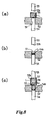
- Fig.8 schematically shows the procedures of the prior tablet production method disclosed in JP-A-56-14098.
- lubricant L is sprayed in a spray 56 provided above a die 51 of a rotary table 52 as shown in Fig.8(a).
- lubricant L is placed on a surface (upper surface) 54s of a lower punch 54 as shown in Fig.8(b). Compressed air is sprayed against the lower punch 54 from a nozzle 58 provided in a spraying chamber 57 which is provided separately from the spray 56. The lubricant L on the lower punch 54 is blown to be dispersed and the dispersed lubricant L is attached on a surface (inner wall) 51s of the die 51 and the surface (lower surface) 53s of the upper punch 53 as shown in Fig.8(c).
- molding material (not shown) is compressed to produce a tablet by means of the die 51, the upper punch 53, and the lower punch 54 of which surface (inner wall) 51s, the surface (lower surface) 53s, and the surface (upper surface) 54s are lubricated.
- JP-A-7-124231 The tablet production method disclosed in JP-A-7-124231 has been proposed by the present inventors in order to solve the above-mentioned problems.
- Fig.9 schematically shows the procedures of the tablet production method disclosed in JP-A-7-124231.
- a tabletting machine in which a pulsating vibration air generation means 67 is connected above the die 51 before a step for charging molding material in the die 51 and a spraying chamber 58 having a spray nozzle 59 for spraying lubricant L is provided is prepared.
- molding material is charged in the die 51.
- molding material m is compressed to produce a tablet by means of the upper punch 53 and the lower punch 54 of which surfaces (lower surface 53s and upper surface 54s) are lubricated.
- lubricant L can be uniformly and stably applied on the dies 51 and the punches 53, 54 by pulsating vibration air in a step of applying lubricant L so that material m is prevented from sticking on the punches 53, 54 and the die 51 and material can be continuously tabletted smoothly and stably for a long time, comparing to the production methods disclosed in JP-B-41-11273 and JP-A-56-14098.
- the present invention is proposed to solve the above-mentioned problems.
- the object of the invention is to provide a method for producing tablet wherein molding material doesn't cause sticking and so on for the punches and the dies of the tabletting machine, tabletting can be continuously executed stably for a long time, it can be executed as an industrial tabletting method, and properties of the produced tablet such as disintegration time and hardness and absorption speed of active component into body don't differ from a tablet produced by a normal internal lubricant method.
- another object of the present invention is to provide a newly constructed tablet produced according to this tablet production method.
- a tablet including active component, diluting agent, and lubricant is produced by means of a tabletting machine provided with punches and dies, comprising steps of; preparing molding material including active component, diluting anent, and a part of lubricant; applying most of remaining amount of the lubricant on a surface of the punch and a surface of the die; and tabletting the molding material by means of the punches on which surfaces the lubricant is applied and the die on which surface the lubricant is applied.
- diluting agent in this specification means medicinal additive excluding lubricant. Namely it means that the term “diluting agent” may include excipient used for shaping a tablet (formation), supplement such as solubilizing agent, solubilizer, buffering agent, hardening agent, binder and so on other than lubricant, adjuvant such as antioxidant, preservative, aroma, sweetening agent, colorant, and so on if required.
- Lubricant isn't specifically limited, for example, there are stearate acid metal salt (magnesium stearate, calcium stearate and so on), stearic acid, sodium lauryl sulfate, sodium lauryl magnesium, powdered gum arabic, carnauba wax, anhydrous silicic acid, magnesium oxide, silic acid hydrate, boric acid, fatty acid sodium salt, leucine, and so on which have been commonly used. One of them may be used solely or more than two of them may be combined.
- stearate acid metal salt magnesium stearate, calcium stearate and so on
- stearic acid sodium lauryl sulfate
- sodium lauryl magnesium powdered gum arabic, carnauba wax, anhydrous silicic acid, magnesium oxide, silic acid hydrate, boric acid, fatty acid sodium salt, leucine, and so on which have been commonly used.
- stearate acid metal salt magnesium stearate, calcium stearate and so
- the used amount of lubricant per a tablet is preferably adjusted to be almost the same as the lubricant amount used in an internal lubricant method.
- punch generally means a pair of an upper punch and a lower punch and "punch surfaces” means a surface of an upper punch and a surface of a lower punch when punch means a pair of an upper punch and a lower punch.
- die surface in this specification means an inner circumferential wall of a die above an upper surface of a lower punch when the lower punch is inserted in a predetermined position in the die.
- Means for applying the remaining amount of lubricant on the punch surfaces and die surface isn't particularly limited. Means disclosed in JP-B-41-11273, JP-B-48-20103, JP-A-56-14098, JP-A-59-205970, JP-A-4-295366, and JP-A-7-124231 may be used.
- the method described in claim 2 concretely suggests a preferable step for applying most of the remaining amount of lubricant on the punch surfaces and the die surface.
- the step of applying most of remaining amount of the lubricant on the punch surfaces and the die surface is provided with a step of housing the punches and the die in a spraying chamber, and a step of spraying the most of remaining amount of lubricant while dispersing in the air in the spraying chamber.
- the size of the spraying chamber it is almost the same as or a little larger than the diameter of the die and also has a height for housing at least the lower surface of the upper punch positioned above the die.
- Air used for spraying lubricant in the spraying chamber may be steady pressure air or pulsating vibration air.
- the step of spraying most of the remaining amount of lubricant in the spraying chamber is a step of spraying most of the remaining amount of lubricant while dispersing in positive steady pressure air.
- steady pressure air in this specification means air of which pressure is hardly changed.
- the step of spraying most of the remaining amount of lubricant in the spraying chamber is a step of spraying most of the most of the remaining amount of lubricant while dispersing in positive pulsating vibration air.
- Pulsating vibration air in this specification means air of which pressure changes with time.
- Pressure in the spraying chamber means that the pressure in the spraying chamber is higher than atmosphere outside thereof.
- Pulsitive pulsating vibration air used in this invention includes both positive pulsating vibration air of which peak and valley are positive and positive pulsating vibration air of which peak is positive and valley is atmospheric pressure.
- the step of applying most of the remaining amount of the lubricant on the punch surfaces and the die surface is comprised of the steps of; housing the punches and the die in the spraying chamber; and spraying most of the remaining amount of lubricant in the spraying chamber, and applying the lubricant on the punch surfaces and the die surface while generating pulsating vibration air in the spraying chamber.
- Any pulsating vibration air having several periods and strengths may be used if it can forcibly diffuse lubricant particle sprayed in the spraying chamber by generating air vibration all around therein regardless that air pressure is positive or negative.
- negative pressure in this specification means that the pressure in the spraying chamber is lower than atmospheric pressure outside thereof.
- Negative pulsating vibration air used in this invention includes both pulsating vibration air of which peak and valley are negative and pulsating vibration air of which peak is atmospheric pressure and valley is negative.
- pulsating vibration air varies depending on the size and shape of the punches and the dies of the tabletting machine, the size and shape of the spraying chamber, attachment method of the spraying means, property of active component, and so on, it can't be generally defined so that it is defined based on experiments.
- the method described in claim 6 defines the ratio of the lubricant amount included in a tablet and the lubricant applied on the punch surfaces and the die surface. It is controlled that the part of lubricant contained in the molding material as set forth in claims 1 - 5 is greater than or equal to about 60 weight percent and less than or equal to about 99.99 weight percent for the entire amount of lubricant used for a tablet, and the most of the remaining amount of lubricant is greater than or equal to about 0.01 weight percent and less than or equal to about 40 weight percent for the entire amount of lubricant used for a tablet.
- the entire amount of lubricant used for a tablet in this specification means the used amount (weight) of lubricant for one tablet included in molding material used when a tablet is produced according to an internal lubricant method.
- the method as set forth in claim 7 defines the ratio of the lubricant amount included in a tablet and the lubricant applied on the punch surfaces and the die surface. It is controlled that the part of lubricant contained in the molding material described in claims 1- 5 is greater than or equal to about 80 weight percent and less than or equal to about 99.99 weight percent for the entire amount of lubricant used for a tablet, and the most of the remaining amount of lubricant is greater than or equal to about 0.01 weight percent and less than or equal to about 20 weight percent for the entire amount of lubricant used for a tablet.
- the entire amount of lubricant used for a tablet in the claims 1 - 7 is almost the same as the entire amount used for a tablet produced by an internal lubricant method.
- the entire amount of lubricant used for a tablet in claims 1 - 7 is greater than or equal to 0.01 weight percent and less than or equal to 5 weight percent for the entire weight of a tablet.
- the amount of lubricant included in a tablet is almost the same as the entire amount of lubricant for a tablet used in an internal lubricant method. Accordingly, when the method described in claim 7 or 8 is used, a tablet of which properties such as disintegration time and hardness and absorption dynamic state don't change comparing to a tablet produced according to an internal lubricant method can be produced.
- the tablet described in claim 10 defines construction of a tablet produced according to the methods described in claims 1 - 9.
- the tablet described in claim 10 includes lubricant therein, and at least a part of lubricant applied on punch surfaces and a die surface used for molding material is accreted to the surface of the tablet with pressure.
- lubricant isn't added to molding material and is applied on punch surfaces and a die surface.
- a tablet produced by this method doesn't include lubricant therein and at least a part of lubricant applied on punch surfaces and a die surface at the time of tabletting is accreted with pressure only on the surface of a tablet.
- the tablet described in claim 10 includes lubricant therein and further at least a part of lubricant applied on punch surfaces and a die surface at the time of tabletting is accreted with pressure only on the surface of the tablet.
- a layer including lubricant per unit volume greater than the lubricant per unit volume included in the tablet is formed at an outer area of the tablet.
- disintegration characteristic and elution characteristic are similar to that of a tablet produced by the prior internal lubricant method.
- the tablet described in claim 10 can effectively prevent tabletting problems (such as sticking) because physical properties such as disintegration time and hardness and absorption dynamic state into a body of the produced tablet don't change comparing to a tablet produced by an internal lubricant method and also the lubricant density of the surface of the produced tablet is high.
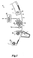
- Fig.1 shows schematic construction by enlarging one part around a rotary table of a rotary type tabletting machine used for executing the present invention.
- Fig 2 is a schematic section when one part of Fig.1 around the rotary table is enlarged.
- the tabletting machine (rotary type tabletting machine) A is comprised of a rotatably provided rotary table 2 having plural dies 1, ⁇ in circumferential direction, plural upper punches 3, ⁇ and plural lower punches 4, ⁇ provided so as to correspond to each die 1, ⁇ .
- a spraying chamber 8 is provided at P1 which is before a point P2 where molding material is charged in the die 1.
- a pulsating vibration air generation means 7A is connected to the spraying chamber 8 and a spray nozzle 9A for spraying lubricant L is provided in the spraying chamber 8.
- the upper punches 3 and the lower punches 4 rotate together with the rotary table 2 while moving up and down by means of a cam 40 and a cam groove 41 and the punches 3, 4 are designed to compress molding material m charged in the dies 1.
- the spraying chamber 8 is provided so as to surround from an upper circumferential end 1e of the die 1 to a lower surface 3s of the upper punch 3 positioned thereover as shown in Fig.1 and Fig.2. Further the spraying chamber 8 is provided with an opening 8a at its upper part and the upper punch 3 is designed to be inserted in a predetermined part in the spraying chamber 8 through the opening 8a.
- the spraying chamber 8 At the position where the spraying chamber 8 is provided, it is designed such that the lower punch 4 comes down in the die 1 as far as possible and preferably the lower punch 4 becomes a lowest supporting point.
- an air source 10 such as a cylinder charged with compressed air is connected to the spray nozzle 9A and lubricant L is sprayed from the spray nozzle 9A together with compressed air by means of air generated from the air source 10.
- the member indicated by a numeral 5 is a material supply chute
- the member indicated by a numeral 6 shows a feed shoe
- the member indicated by a numeral 6s is a scraper.
- this tabletting machine (rotary type tabletting machine) A molding material m is charged in the die 1 by means of the material supply chute 5 and the feed shoe 6 when the die 1 is positioned at the point P2 for charging molding material m accompanied with rotation of the rotary table 2 and extra molding material is scraped off by the scraper 6s.
- Fig.2 the members shown as Ra, Rb indicate a roll for controlling main pressure respectively and the members shown as Rc, Rd are rollers for controlling auxiliary pressure.
- the height of the upper punches 3 ⁇ , and the lower punches 4 ⁇ attached with the rolls Ra - Rd are accurately controlled by controlling the height of these rollers Ra - Rd.
- a nozzle which can spray a desired lubricant L in the spraying chamber 8 by supplying air pressure may be used as the spray nozzle 9A.
- cartridge type nozzle, pressure tank type nozzle, or mini hopper type nozzle may be used.
- Lubricant L isn't particularly limited if it is known one.
- stearic acid metal salt such as magnesium stearate and calcium stearate, sodium lauryl sulfate, talc, and so on.
- kinds of lubricant L are properly selected according to molding material m.
- the ratio of the amount Wc of lubricant L contained in molding material m and the amount We of lubricant L sprayed on the surfaces 3s, 4s of the punches and the surface (inner wall) 1s of the die 1 is determined.
- the amount We of lubricant L for spraying the surfaces 3s, 4s of the punches 3, 4 and the surface (inner wall) is of the die 1 is preferably adjusted such that the sum of the amount Wc of lubricant L contained in molding material m and the amount We of lubricant L sprayed on the surfaces 3s, 4s, and is equals to or a little greater than the entire amount Wa of lubricant L contained per a tablet produced by an internal lubricant method ( Wa ⁇ Wc + We ), anticipating the amount of lubricant L which isn't applied on the surfaces 3s, 4s and 1s in the spraying chamber 8 and the amount of lubricant L remained on the surfaces 3s, 4s, 1s without being accreted by pressure to a produced tablet when tabletting.
- the amount of lubricant L sprayed in the spraying chamber 8 is varied, lubricant L is applied on the surfaces 3s, 4s of the punches 3, 4, the surface (inner wall) is of the die 1, and molding material is tabletted by means of the lubricated punches 3, 4 and die 1.
- the amount of lubricant L accreted by pressure on a produced tablet from the lubricated surfaces 3s, 4s, 1s is measured and the amount of lubricant L which isn't applied on the surfaces 3s, 4s, 1s in the spraying chamber 8 is adjusted.
- the flow amount of compressed air generated from the air source 10 and operating condition of pulsating vibration air generation means 7A may be varied.
- the entire amount Wa of lubricant L is preferably greater than or equal to 0.01 weight % and less than or equal to 5 weight % of the entire weight of one tablet.
- lubricant L is generally combined in molding material so as to be greater than or equal to 0.01 weight % and less than or equal to 5 weight % of the entire weight of one tablet.
- the ratio of the amount Wc of lubricant L contained in a tablet and the amount We applied on the surfaces 3s, 4s of the punches 3, 4 and the surface (inner wall) 1s of the die 1 is preferably adjusted such that the amount Wc of lubricant L contained in molding material m is greater than or equal to 60 weight % and less than or equal to 99.99 weight % of the entire weight of lubricant L used for one tablet and the amount We of lubricant L sprayed in the spraying chamber 8 is preferably greater than or equal to 0.01 weight % and less than or equal to 40 weight % of the entire amount Wa of lubricant L used for one tablet.
- the ratio of the amount Wc of lubricant L contained in a tablet and the amount We applied on the surfaces 3s, 4s of the punches 3, 4 and the surface (inner wall) 1s of the die 1 is more preferably adjusted such that the amount Wc of lubricant L contained in molding material m is greater than or equal to 80 weight % and less than or equal to 99.99 weight % of the entire weight of lubricant L used for one tablet and the amount We of lubricant L sprayed in the spraying chamber 8 is preferably greater than or equal to 0.01 weight % and less than or equal to 20 weight % of the entire amount Wa of lubricant L used for one tablet.
- the rotary table 2 is rotated at a prescribed speed.
- pulsating vibration air generation means 7A is driven to generate pulsating vibration air in the spraying chamber 8
- lubricant L is applied on the surface (inner wall) 1s of the die 1, the surface (lower surface) 3s of the upper punch 3, and the surface (upper surface) 4s of the lower punch 4 by spraying lubricant L from the spray nozzle 9A.
- the molding material (lubricant L is mixed therein at a ratio of amount Wc per a tablet) is charged in the die 1 at P2 positioned accompanying the rotary table 2 and extra material is scraped off.
- Fig.3 is an enlarged schematic section of the substantial part of the tabletting machine A.
- Fig.3(a) shows construction of the spraying chamber 8 and Fig.3(b) explains pulsating vibration air generation means 7A.
- the pulsating vibration air generation means 7A is connected to the spraying chamber 8 via a conduit 13A as shown in Fig.3(a).
- the numeral 71 indicates a blower
- 72 indicates a cylindrical tube
- 73 indicates a valve element provided rotatably in the tube 72 around a rotary axis 74 so as to divide the inside of the tube 72 into two parts.
- the conduit 13A and a conduit 14A coupled to the blower 71 are connected at a prescribed part of the side of the tube 72.
- the valve element 73 is designed to be rotated at a desired rotational velocity by a valve rotation control means (not shown).
- blower 71 If the blower 71 is rotated at a prescribed rotation number, current directing from the tube 72 to the blower 71 is generated in the conduit 14A.
- valve element 73 is rotated at a prescribed rotational velocity while the blower 71 is rotated at a prescribed rotation number.
- the valve element 73 is positioned as shown in solid line in Fig.3(b)
- the spraying chamber 8 and the blower 71 are connected, and when the valve element is positioned as shown in dotted line, they are shut off by the valve element 73.
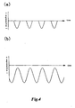
- pulsating vibration air of which peak is atmospheric pressure and valley is negative pressure as shown in Fig.4(a) or pulsating vibration air of which peak and valley are negative pressure as shown in Fig.4(b) is generated in the spraying chamber.
- negative pressure means that the pressure in the spraying chamber 8 is lower than the pressure outside of the chamber 8 (atmospheric pressure).
- Extra lubricant L in the spraying chamber 8 is designed to be discharged from the chamber 8 by means of negative pulsating vibration air.
- lubricant L can be uniformly applied on the surface (inner wall) 1s of the die 1, the surface (lower surface) 3s of the upper punch 3 and the surface (upper surface) 4s of the lower punch 4 both of which are provided for the die 1 contained in the spraying chamber 8.
- lubricant L can be uniformly applied on the surface (inner wall) 1s of the die 1, the surface (lower surface) 3s of the upper punch 3, and the surface (upper surface) 4s of the lower punch 4, even if the amount of lubricant L sprayed in the spraying chamber 8 is only minute, molding material m can be prevented from causing sticking on the dies 1 and the upper and lower punches 3, 4 of the tabletting machine A regardless of kinds of active component, diluting agent, and lubricant L. Consequently, the spraying amount of lubricant L used for one tabletting can be remarkably reduced.
- the tablet produced according to the above-mentioned method includes lubricant L inside thereof and at least a part of the accreted amount of lubricant L applied on the surfaces 3s, 4s, 1s is added.
- the tablet is constructed with a layer including lubricant of which amount per unit volume is greater than the lubricant included in the tablet.
- this tablet has a construction different from the tablet in which lubricant L is added in molding material m, mixed evenly, and compressed so that lubricant is uniformly contained in and on the tablet according to the prior internal lubricant method.
- the tablet has a different construction from the tablet in which lubricant isn't included in molding material m and is applied on the surfaces 53s, 54s of the punches 53, 54 and the surface 51s of the die 51 in order that the tablet doesn't include lubricant therein and only a part of the lubricant applied on the punches and dies is accreted thereon by pressure according to the prior external lubricant spraying method.
- the tablet includes lubricant L disintegration characteristic and elution characteristic thereof are approximate to that of the tablet produced according to the prior internal lubricant method.
- disintegration characteristic and elution characteristic thereof are approximate to that of the tablet produced according to the prior internal lubricant method.
- the member indicated by reference number 15A in Fig.3(a) is a storage for powdered lubricant L.
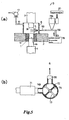
- Fig.5 is a sectional view of an enlarged substantial part of other tabletting machine preferable to the tablet production method of the present invention.
- Fig.5(a) explains construction of the spraying chamber 8 and
- Fig.5(b) explains construction of the pulsating vibration air generation means 7B used for the tabletting machine.
- the tabletting machine (rotary type tabletting machine) B has the same construction as the tabletting machine (rotary type tabletting machine) A in Fig.1, so the same members have the same numerals and their explanations are omitted.
- the pulsating vibration air generation means 7B is connected to the spraying chamber 8 via a conduit 13B.
- the numeral 71 indicates a blower
- 72 indicates a cylindrical tube
- 73 indicates a valve element provided rotatably in the tube 72 around a rotary axis 74 so as to divide the inside of the tube 72 into two parts.
- the conduit 13B and a conduit 14B coupled to the blower 71 are connected at a prescribed part of the side of the tube 72.
- the valve element 73 is designed to be rotated at a desired rotational velocity by a valve rotation control means (not shown).
- blower 71 If the blower 71 is rotated at a prescribed rotation number, current directing from the tube 72 to the blower 71 is generated in the conduit 14B.
- valve element 73 is rotated at a prescribed rotational velocity while the blower 71 is rotated at a prescribed rotation number.
- the valve element 73 is positioned as shown in solid line in Fig.5(b)
- the spraying chamber 8 and the blower 71 are connected, and when the valve element 78 is positioned as shown in dotted line, they are shut off by the valve element 73.
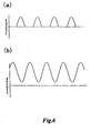
- pulsating vibration air of which peak is positive pressure and valley is atmospheric pressure as shown in Fig.6(a) or pulsating vibration air of which peak and valley are positive pressure as shown in Fig.6(b) is generated in the spraying chamber 8.
- positive pressure means that the pressure in the spraying chamber 8 is higher than the pressure outside of the chamber 8 (atmospheric pressure).
- a spray nozzle 9B is connected at the tip end of the conduit 13B.
- a hopper 15B is connected in midway of the conduit 13B (between the spray nozzle 9B and the pulsating vibration air generation means 7B).
- Lubricant powder L is stored in the hopper 15B.
- lubricant powder L is discharged from the hopper 15 to the conduit 13B, mixed with positive pulsating vibration air in the conduit 13B, diffused therein, transported to the spray nozzle 9B pneumatically, then lubricant L is sprayed from the nozzle 9B with positive pulsating vibration air in the spraying chamber 8.
- the lubricant sprayed in the spraying chamber 8 is diffused by positive pulsating vibration air and is uniformly applied on the surface (inner wall) 1s of the die 1, the surface (lower surface) 3s of the upper punch 3, and the surface (upper surface) 4s of the lower punch 4, wherein the punches 3, 4 are provided corresponding to the die 1 and all of them are contained in the spraying chamber 8.
- an air suction means 17 such as a blower is connected to the spraying chamber 8 via a conduit 16
- extra lubricant L can be discharged from the spraying chamber 8 when the air suction means 17 is driven.
- lubricant can be uniformly applied on the surface (inner wall) 1s of the die 1, the surface (lower surface) 3s of the upper punch 3, and the surface (upper surface) 4s of the lower punch 4.
- lubricant can be uniformly applied on the surfaces 1s, 3s, 4s, even if the amount of sprayed lubricant is extremely a little, molding material m can be prevented from sticking on the die 1, the upper punch 3, and the lower punch 4 of the tabletting machine B regardless of kinds of active component, diluting agent, and lubricant L. As a result, spraying amount of lubricant for one tabletting can be significantly reduced.
- the member shown as 20 in Fig. 5 indicates compressed air supply means for adjusting amount of lubricant powder L supplied to the conduit 13B from the hopper 15B.
- Pulsating vibration air to be supplied in the spraying chamber 8 in the present invention may be positive or negative as mentioned above.
- glybuzole and mannitol were mixed at a ratio of 7 : 3, polyvinyl alcohol was sprayed, granule having a prescribed particle size and prescribed particle size distribution was manufactured, and the obtained granule was sized by means of a No.28 mesh.
- magnesium stearate (powder, Japanese Pharmacopoeia product) was added to the granule as lubricant L, they were well mixed by a V-type mixer, and they were tabletted to produce a 200mg tablet at a speed of rotating a rotary table at 30 times per a minute by means of the tabletting machine A with 8mm diameter punch and die set.
- the amount of the magnesium stearate sprayed in the spraying chamber 8 was adjusted such that weight % of lubricant L included in one produced tablet was 0.03 weight % for the entire amount of the tablet.
- WSG-type 15 by Glatt Co., Ltd. was used as a fluid-bed granulator and HATA HT-X20 by Hata Seisakusho Co., Ltd. was used as a main body of a tabletting machine.
- Pulsating vibration air which was always negative and frequency was 10Hz as shown in Fig.4(b) was used in the experiment 1. However such conditions aren't limited.
- Magnesium stearate was added to the granule produced like the experiment 1 as lubricant L in such a manner the amount of magnesium stearate became 1.0 weight % for the entire weight of one tablet. They were well mixed by a V-type mixer, and they were tabletted to produce a 200mg tablet at a speed of rotating a rotary table at 30 times per a minute by means of the tabletting machine A with 8mm diameter punch and die set.
- HATA HT-X20 by Hata Seisakusho Co., Ltd. was used as a tabletting machine.
- the tablet produced according to the present invention had the same hardness as the tablet produced by the prior internal lubricant method when material was compressed at the same tabletting pressure.
- disintegration test Japanese Pharmacopoeia, general test method
- dissolution test Japanese Pharmacopoeia, general test method
- magnesium stearate (Sakai Chemical Industry Co., Ltd.) was added to thus obtained granule and they were mixed for 3 minutes by a V-type mixer.
- the punches 3, 4 of which surfaces 3s, 4s were applied with magnesium stearate and the die 1 of which surface (inner wall) 1s was applied with magnesium stearate were used.
- the amount of magnesium stearate sprayed in the spraying chamber 8 to be applied on the surfaces 3s, 4s, 1s was adjusted such that the weight % of lubricant L contained per one produced tablet became 0.1 weight % for the entire weight of one tablet.
- the mixture was tabletted by means of the punches 3, 4 and the die 1 of which surfaces 3s, 4s, 1s were applied with magnesium stearate (Sakai Chemical Industry Co., Ltd.).
- the amount of magnesium stearate sprayed in the spraying chamber 8 to be applied on the surfaces 3s, 4s, 1s was adjusted such that the weight % of lubricant L contained per one produced tablet become 0.2 weight % for the entire weight of one tablet.
- the mixture was tabletted by means of the punches 3, 4 and the die 1 of which surfaces 3s, 4s, 1s were applied with magnesium stearate (Sakai Chemical Industry Co., Ltd.).
- the amount of magnesium stearate sprayed in the spraying chamber 8 to be applied on the surfaces 3s, 4s, 1s was adjusted such that the weight % of lubricant L contained per one produced tablet became 0.3 weight % for the entire weight of one tablet.
- the mixture was tabletted by means of the punches 3, 4 and the die 1 of which surfaces 3s, 4s, 1s were applied with magnesium stearate (Sakai Chemical Industry Co., Ltd.).
- Magnesium stearate contained in the tablet produced by the comparison 2 was 0.45 weight % - 0.55 weight % for the entire weight of one tablet.
- the amount of magnesium stearate sprayed in the spraying chamber 8 to be applied on the surfaces 3s, 4s, 1s was adjusted such that the weight % of lubricant L contained per one produced tablet became 0.001 weight % for the entire weight of one tablet.
- the mixture was tabletted by means of the punches 3, 4 and the die 1 of which surfaces 3s, 4s, 1s were applied with magnesium stearate (Sakai Chemical Industry Co., Ltd.).
- Comparison 4 shows when a tablet is produced by the prior internal lubricant method.
- lubricant L wasn't included in molding material.
- molding material was continuously tabletted by the punches 3, 4 of which surfaces 3s, 4s were applied with magnesium stearate (Sakai Chemical Industry Co., Ltd.) and the die 1 of which surface (inner wall) 1s was applied with magnesium stearate.
- the amount of magnesium stearate sprayed in the spraying chamber 8 to be applied on the surfaces 3s, 4s, 1s was adjusted such that the weight % of lubricant L contained per one produced tablet become 0.1 weight % for the entire weight of one tablet.
- the mixture was tabletted by means of the punches 3, 4 and the die 1 of which surfaces 3s, 4s, 1s were applied with magnesium stearate (Sakai Chemical Industry Co., Ltd.).
- Magnesium stearate contained in the tablet produced by the comparison 5 was 0.15 weight % - 0.25 weight % for the entire weight of one tablet.
- Disintegration test according to a general test method "disintegration test method" described in Japanese Pharmacopoeia was executed. Where water was used as test solution.
- the amount of magnesium stearate applied on the surfaces 3s, 4s of the punches 3, 4 and the surface (inner wall) 1s of the die 1 was preferably 0.001 weight % in order to prevent sticking.
- the ratio of the amount Wc of lubricant L contained in a tablet and the amount We applied on the surfaces 3s, 4s of the punches 3, 4 and the surface (inner wall) 1s of the die 1 was preferably adjusted such that the amount Wc of lubricant L contained in molding material m was greater than or equal to 60 weight % and less than or equal to 99.99 weight % of the entire weight of lubricant L used for one tablet and the amount We of lubricant L sprayed in the spraying chamber 8 was preferably greater than or equal to 0.01 weight % and less than or equal to 40 weight % of the entire amount Wa of lubricant L used for one tablet.
- the ratio of the amount Wc of lubricant L contained in a tablet and the amount We applied on the surfaces 3s, 4s of the punches 3, 4 and the surface (inner wall) 1s of the die 1 was more preferably adjusted such that the amount Wc of lubricant L contained in molding material m was greater than or equal to 60 weight % and less than or equal to 99.99 weight % of the entire weight of lubricant L used for one tablet and the amount We of lubricant L sprayed in the spraying chamber 8 is preferably greater than or equal to 0.02 weight % and less than or equal to 40 weight % of the entire amount Wa of lubricant L used for one tablet.
- the ratio of the amount Wc of lubricant L contained in a tablet and the amount We applied on the surfaces 3s, 4s of the punches 3, 4 and the surface (inner wall) 1s of the die 1 was more preferably adjusted such that the amount Wc of lubricant L contained in molding material m was greater than or equal to 80 weight % and less than or equal to 99.99 weight % of the entire weight of lubricant L used for one tablet and the amount We of lubricant L sprayed in the spraying chamber 8 was preferably greater than or equal to 0.01 weight % and less than or equal to 20 weight % of the entire amount Wa of lubricant L used for one tablet.
- the ratio of the amount Wc of lubricant L contained in a tablet and the amount We applied on the surfaces 3s, 4s of the punches 3, 4 and the surface (inner wall) 1s of the die 1 was more preferably adjusted such that the amount Wc of lubricant L contained in molding material m was greater than or equal to 80 weight % and less than or equal to 99.98 weight % of the entire weight of lubricant L used for one tablet and the amount We of lubricant L sprayed in the spraying chamber 8 was preferably greater than or equal to 0.02 weight % and less than or equal to 20 weight % of the entire amount Wa of lubricant L used for one tablet.
- pulsating vibration air isn't limited to them and frequency of pulsating vibration air may be selected depending on description and particle size of lubricant L so that lubricant L is easily mixed and diffused therein.
- Driving condition of the blower 71 may be set depending on the size of the spraying chamber 8 and description and particle size of the lubricant L in such a manner that lubricant L is easily mixed and diffused in air.
- a part of lubricant used for producing a tablet by the prior internal lubricant method is applied on the surfaces of the punches and the dies. Therefore, comparing to the tablet production method by the prior internal lubricant method, molding material can be prevented from adhering on the punches and dies of the tabletting machine and tabletting problem such as sticking is hardly caused for produced tablets.
- lubricant is included in the tablet.
- a tablet of which physical property such as disintegration time and hardness and absorption dynamic state into body don't change can be effectively produced comparing to the tablet production method by the prior internal lubricant method.
- a supplier of pharmaceutical drugs can solve tabletting problems such as sticking caused at the time of tabletting without changing bioavailablility of drugs.
- the punches and the dies are housed in the spraying chamber and remaining amount of lubricant diffused in positive steady pressure air is sprayed for applying on the surfaces of the punches and the die, so that lubricant of constant condition can be always applied on the surfaces.
- lubricant of constant condition can be always applied on the surfaces.
- the punches and the die are housed in the spraying chamber and remaining amount of lubricant diffused in positive pulsating vibration air is sprayed for applying on the surfaces of the punches and the die.
- sprayed lubricant in the spraying chamber is forcibly diffused in positive pulsating vibration air and easily attached on the surfaces of the punches and die.
- a tablet of which property such as disintegration time and hardness doesn't change can be effectively produced comparing to the tablet produced by the prior internal lubricant method.
- the amount of lubricant included in a tablet is almost the same as the entire lubricant amount used for a tablet produced by the internal lubricant method. Therefore, when the method described in claim 8 or 9 is used, a tablet of which property such as disintegration time and hardness and absorption dynamic state don't change comparing to the tablet produced by the prior internal lubricant method can be effectively produced.
- the tablet described in claim 10 includes lubricant therein, property such as disintegration time and hardness and absorption dynamic state of produced tablet don't change comparing to the tablet produced by the prior internal lubricant method.
Landscapes
- Engineering & Computer Science (AREA)
- Mechanical Engineering (AREA)
- Health & Medical Sciences (AREA)
- Life Sciences & Earth Sciences (AREA)
- Medicinal Chemistry (AREA)
- Pharmacology & Pharmacy (AREA)
- Chemical & Material Sciences (AREA)
- Animal Behavior & Ethology (AREA)
- General Health & Medical Sciences (AREA)
- Public Health (AREA)
- Veterinary Medicine (AREA)
- Medicinal Preparation (AREA)
- Medical Preparation Storing Or Oral Administration Devices (AREA)
- Pharmaceuticals Containing Other Organic And Inorganic Compounds (AREA)
Applications Claiming Priority (3)
| Application Number | Priority Date | Filing Date | Title |
|---|---|---|---|
| JP9332812A JPH11169437A (ja) | 1997-12-03 | 1997-12-03 | 錠剤の製造方法 |
| JP33281297 | 1997-12-03 | ||
| PCT/JP1998/005474 WO1999027887A1 (fr) | 1997-12-03 | 1998-12-03 | Procede relatif a la fabrication de comprimes, et comprimes |
Publications (3)
| Publication Number | Publication Date |
|---|---|
| EP1043009A1 true EP1043009A1 (fr) | 2000-10-11 |
| EP1043009A4 EP1043009A4 (fr) | 2003-04-02 |
| EP1043009B1 EP1043009B1 (fr) | 2007-02-14 |
Family
ID=18259085
Family Applications (1)
| Application Number | Title | Priority Date | Filing Date |
|---|---|---|---|
| EP98957166A Revoked EP1043009B1 (fr) | 1997-12-03 | 1998-12-03 | Comprimes et procede pour la fabrication de comprimes |
Country Status (13)
| Country | Link |
|---|---|
| US (1) | US6432534B1 (fr) |
| EP (1) | EP1043009B1 (fr) |
| JP (2) | JPH11169437A (fr) |
| KR (1) | KR20010032712A (fr) |
| AT (1) | ATE353618T1 (fr) |
| AU (1) | AU755056C (fr) |
| CA (1) | CA2312736C (fr) |
| CY (1) | CY1106377T1 (fr) |
| DE (1) | DE69837108T2 (fr) |
| DK (1) | DK1043009T3 (fr) |
| ES (1) | ES2281939T3 (fr) |
| PT (1) | PT1043009E (fr) |
| WO (1) | WO1999027887A1 (fr) |
Cited By (2)
| Publication number | Priority date | Publication date | Assignee | Title |
|---|---|---|---|---|
| EP1666237A3 (fr) * | 2004-10-20 | 2006-10-18 | Fette GmbH | Presse rotative |
| EP1222917A4 (fr) * | 1999-10-13 | 2007-01-17 | Kyowa Hakko Kogyo Kk | Produit moule par compression et son procede de production |
Families Citing this family (18)
| Publication number | Priority date | Publication date | Assignee | Title |
|---|---|---|---|---|
| US8071128B2 (en) | 1996-06-14 | 2011-12-06 | Kyowa Hakko Kirin Co., Ltd. | Intrabuccally rapidly disintegrating tablet and a production method of the tablets |
| AU763143B2 (en) * | 1998-04-08 | 2003-07-17 | Kyowa Hakko Kirin Co., Ltd. | Tablet manufacturing method and tablet |
| WO2000021740A1 (fr) * | 1998-10-13 | 2000-04-20 | Kyowa Hakko Kogyo Co., Ltd. | Procede d'application d'un materiau en poudre, procede de production de comprimes, dispositif d'application d'un materiau en poudre pour poinçon superieur et pour poinçon inferieur, dispositif d'application d'un materiau en poudre et machine de compression a lubrification externe |
| US7131828B2 (en) | 2000-04-12 | 2006-11-07 | Kyowa Hakko Kogyo Co., Ltd. | Coating device for powder material |
| AU2002237548B2 (en) * | 2001-03-06 | 2007-04-05 | Kyowa Hakko Kogyo Co., Ltd. | Intraorally rapidly disintegrable tablet |
| US9358214B2 (en) | 2001-10-04 | 2016-06-07 | Adare Pharmaceuticals, Inc. | Timed, sustained release systems for propranolol |
| US8367111B2 (en) | 2002-12-31 | 2013-02-05 | Aptalis Pharmatech, Inc. | Extended release dosage forms of propranolol hydrochloride |
| US8545881B2 (en) * | 2004-04-19 | 2013-10-01 | Eurand Pharmaceuticals, Ltd. | Orally disintegrating tablets and methods of manufacture |
| US8747895B2 (en) | 2004-09-13 | 2014-06-10 | Aptalis Pharmatech, Inc. | Orally disintegrating tablets of atomoxetine |
| US9884014B2 (en) | 2004-10-12 | 2018-02-06 | Adare Pharmaceuticals, Inc. | Taste-masked pharmaceutical compositions |
| NZ589750A (en) | 2004-10-21 | 2012-07-27 | Aptalis Pharmatech Inc | Taste-masked pharmaceutical compositions with gastrosoluble pore-formers |
| US20060105038A1 (en) * | 2004-11-12 | 2006-05-18 | Eurand Pharmaceuticals Limited | Taste-masked pharmaceutical compositions prepared by coacervation |
| US9161918B2 (en) | 2005-05-02 | 2015-10-20 | Adare Pharmaceuticals, Inc. | Timed, pulsatile release systems |
| ES2607814T3 (es) * | 2008-02-28 | 2017-04-04 | Abbvie Inc. | Preparación de tabletas |
| CN102958515A (zh) | 2009-12-02 | 2013-03-06 | 阿普塔利斯制药有限公司 | 非索非那定微胶囊及含有非索非那定微胶囊的组合物 |
| US20110212171A1 (en) * | 2010-01-08 | 2011-09-01 | Eurand, Inc. | Taste masked topiramate composition and an orally disintegrating tablet comprising the same |
| CN113459574B (zh) * | 2021-06-30 | 2022-09-13 | 湖南嘉恒制药有限公司 | 一种用于粉末药片的压合取出机构 |
| KR102372025B1 (ko) | 2021-08-12 | 2022-03-10 | 금성산기 주식회사 | 타정기의 오픈 휘더 구조 |
Citations (2)
| Publication number | Priority date | Publication date | Assignee | Title |
|---|---|---|---|---|
| US4323530A (en) | 1977-04-20 | 1982-04-06 | Boehringer Ingelheim Gmbh | Method of lubricating compression tools of molding machines |
| JPH10298061A (ja) | 1997-04-25 | 1998-11-10 | Tanabe Seiyaku Co Ltd | 成型製剤及びその製法 |
Family Cites Families (12)
| Publication number | Priority date | Publication date | Assignee | Title |
|---|---|---|---|---|
| JPS4820103B1 (fr) | 1968-05-06 | 1973-06-19 | ||
| JPS5614098A (en) | 1979-07-13 | 1981-02-10 | Takeda Chem Ind Ltd | Externally lubricating tablet making machine |
| DE3312634A1 (de) | 1983-04-08 | 1984-10-11 | Dr. Karl Thomae Gmbh, 7950 Biberach | Verbessertes verfahren und vorrichtungen zum bepunkten von formwerkzeugen mit troepfchen fluessiger oder suspendierter schmiermittel bei der herstellung von formlingen in pharma-, lebensmittel- oder katalysatorenbereich |
| GB8530365D0 (en) * | 1985-12-10 | 1986-01-22 | Univ Bath | Manufacture of moulded products |
| US5056623A (en) * | 1988-12-14 | 1991-10-15 | Dr. Karl Thomae Gmbh | Process for the controlled release of metered quantities of lubricant when coating pressing tools with lubricating liquids and suspensions and apparatus for carrying out the process |
| JP2748563B2 (ja) * | 1989-06-08 | 1998-05-06 | 株式会社ツムラ | 錠剤製造法 |
| JP3082274B2 (ja) | 1991-03-25 | 2000-08-28 | 日清エンジニアリング株式会社 | 錠剤製造法 |
| JPH06218028A (ja) * | 1992-10-02 | 1994-08-09 | Eisai Co Ltd | 湿製錠の成型方法とその装置及び湿製錠 |
| JPH0741406A (ja) * | 1993-06-28 | 1995-02-10 | Sumitomo Chem Co Ltd | 農薬錠剤の製造方法 |
| US5407339A (en) * | 1993-09-27 | 1995-04-18 | Vector Corporation | Triturate tablet machine |
| JP2681601B2 (ja) * | 1993-11-01 | 1997-11-26 | 協和醗酵工業株式会社 | 外部滑沢式打錠機 |
| DE4412117A1 (de) * | 1994-04-08 | 1995-10-12 | Fette Wilhelm Gmbh | Verfahren und Vorrichtung zum Aufbringen von pulverförmigem Schmier- oder Trennmittel auf die Preßwerkzeuge in Tablettiermaschinen |
-
1997
- 1997-12-03 JP JP9332812A patent/JPH11169437A/ja active Pending
-
1998
- 1998-12-03 AU AU13518/99A patent/AU755056C/en not_active Expired
- 1998-12-03 ES ES98957166T patent/ES2281939T3/es not_active Expired - Lifetime
- 1998-12-03 CA CA002312736A patent/CA2312736C/fr not_active Expired - Lifetime
- 1998-12-03 DE DE69837108T patent/DE69837108T2/de not_active Expired - Lifetime
- 1998-12-03 US US09/555,660 patent/US6432534B1/en not_active Expired - Lifetime
- 1998-12-03 PT PT98957166T patent/PT1043009E/pt unknown
- 1998-12-03 JP JP2000522875A patent/JP4154122B2/ja not_active Expired - Lifetime
- 1998-12-03 DK DK98957166T patent/DK1043009T3/da active
- 1998-12-03 WO PCT/JP1998/005474 patent/WO1999027887A1/fr not_active Ceased
- 1998-12-03 EP EP98957166A patent/EP1043009B1/fr not_active Revoked
- 1998-12-03 AT AT98957166T patent/ATE353618T1/de active
- 1998-12-03 KR KR1020007006001A patent/KR20010032712A/ko not_active Ceased
-
2007
- 2007-03-13 CY CY20071100353T patent/CY1106377T1/el unknown
Patent Citations (2)
| Publication number | Priority date | Publication date | Assignee | Title |
|---|---|---|---|---|
| US4323530A (en) | 1977-04-20 | 1982-04-06 | Boehringer Ingelheim Gmbh | Method of lubricating compression tools of molding machines |
| JPH10298061A (ja) | 1997-04-25 | 1998-11-10 | Tanabe Seiyaku Co Ltd | 成型製剤及びその製法 |
Non-Patent Citations (3)
| Title |
|---|
| "Gleimittel", PHARMAZEUTISCHE TECHNOLOGIE, 1991, pages 259 - 260, XP003026163 |
| MILLER T.A.: "Pharmaceutical tablet lubrication", INTERNATIONAL JOURNAL OF PHARMACEUTICS, vol. 41, no. 1-2, 1 January 1998 (1998-01-01), pages 1 - 19, XP023725214 |
| ROWE R.C. ET AL: "COLLOIDAL SILICON DIOXIDE", HANDBOOK OF PHARMACEUTICAL EXCIPIENTS, 1 January 2006 (2006-01-01), pages 188 - 190, XP003016902 |
Cited By (2)
| Publication number | Priority date | Publication date | Assignee | Title |
|---|---|---|---|---|
| EP1222917A4 (fr) * | 1999-10-13 | 2007-01-17 | Kyowa Hakko Kogyo Kk | Produit moule par compression et son procede de production |
| EP1666237A3 (fr) * | 2004-10-20 | 2006-10-18 | Fette GmbH | Presse rotative |
Also Published As
| Publication number | Publication date |
|---|---|
| AU1351899A (en) | 1999-06-16 |
| CA2312736A1 (fr) | 1999-06-10 |
| PT1043009E (pt) | 2007-05-31 |
| ATE353618T1 (de) | 2007-03-15 |
| AU755056B2 (en) | 2002-12-05 |
| EP1043009B1 (fr) | 2007-02-14 |
| DE69837108T2 (de) | 2007-12-13 |
| US6432534B1 (en) | 2002-08-13 |
| AU755056C (en) | 2003-10-30 |
| ES2281939T3 (es) | 2007-10-01 |
| DE69837108D1 (de) | 2007-03-29 |
| KR20010032712A (ko) | 2001-04-25 |
| DK1043009T3 (da) | 2007-05-29 |
| JP4154122B2 (ja) | 2008-09-24 |
| EP1043009A4 (fr) | 2003-04-02 |
| CA2312736C (fr) | 2008-03-25 |
| CY1106377T1 (el) | 2011-10-12 |
| WO1999027887A1 (fr) | 1999-06-10 |
| JPH11169437A (ja) | 1999-06-29 |
Similar Documents
| Publication | Publication Date | Title |
|---|---|---|
| EP1043009A1 (fr) | Procede relatif a la fabrication de comprimes, et comprimes | |
| US6964779B1 (en) | Tablet manufacturing method and tablet | |
| US5213738A (en) | Method for making a capsule-shaped tablet | |
| US7217431B2 (en) | Controlled agglomeration | |
| US5089270A (en) | Capsule-shaped tablet | |
| JP4853695B2 (ja) | 水溶性とそれ以外の活性物質の放出制御錠剤およびその方法 | |
| KR100413581B1 (ko) | 용융성(fusible)담체를함유하는약제학적조성물및그제조방법 | |
| JPWO1999052491A1 (ja) | 錠剤の製造方法及び錠剤 | |
| JP3296412B2 (ja) | 成型製剤及びその製法 | |
| JPWO1999027887A1 (ja) | 錠剤の製造方法及び錠剤 | |
| US20040056375A1 (en) | Method and apparatus for making miniature tablets | |
| JP4568427B2 (ja) | 錠剤の製造方法及び錠剤 | |
| JP2005524670A (ja) | 放出制御投与形態 | |
| EP1222917A1 (fr) | Produit moule par compression et son procede de production | |
| JPWO2000019983A1 (ja) | 錠剤、及び錠剤の製造方法 | |
| WO2000019983A1 (fr) | Comprimes et procede de production de ces comprimes | |
| JPH039757A (ja) | 錠剤製造法 | |
| AU2005299253B2 (en) | Improved tabletting process |
Legal Events
| Date | Code | Title | Description |
|---|---|---|---|
| PUAI | Public reference made under article 153(3) epc to a published international application that has entered the european phase |
Free format text: ORIGINAL CODE: 0009012 |
|
| 17P | Request for examination filed |
Effective date: 20000703 |
|
| AK | Designated contracting states |
Kind code of ref document: A1 Designated state(s): AT BE CH CY DE DK ES FI FR GB GR IE IT LI LU MC NL PT SE |
|
| A4 | Supplementary search report drawn up and despatched |
Effective date: 20030218 |
|
| RIC1 | Information provided on ipc code assigned before grant |
Ipc: 7B 30B 15/00 B Ipc: 7A 61J 3/10 A |
|
| 17Q | First examination report despatched |
Effective date: 20040324 |
|
| GRAP | Despatch of communication of intention to grant a patent |
Free format text: ORIGINAL CODE: EPIDOSNIGR1 |
|
| GRAS | Grant fee paid |
Free format text: ORIGINAL CODE: EPIDOSNIGR3 |
|
| RTI1 | Title (correction) |
Free format text: TABLETS AND PROCESS FOR THE PRODUCTION OF TABLETS |
|
| GRAA | (expected) grant |
Free format text: ORIGINAL CODE: 0009210 |
|
| AK | Designated contracting states |
Kind code of ref document: B1 Designated state(s): AT BE CH CY DE DK ES FI FR GB GR IE IT LI LU MC NL PT SE |
|
| REG | Reference to a national code |
Ref country code: GB Ref legal event code: FG4D |
|
| REG | Reference to a national code |
Ref country code: CH Ref legal event code: EP |
|
| REF | Corresponds to: |
Ref document number: 69837108 Country of ref document: DE Date of ref document: 20070329 Kind code of ref document: P |
|
| REG | Reference to a national code |
Ref country code: IE Ref legal event code: FG4D |
|
| REG | Reference to a national code |
Ref country code: GR Ref legal event code: EP Ref document number: 20070400828 Country of ref document: GR |
|
| REG | Reference to a national code |
Ref country code: SE Ref legal event code: TRGR |
|
| REG | Reference to a national code |
Ref country code: DK Ref legal event code: T3 |
|
| REG | Reference to a national code |
Ref country code: PT Ref legal event code: SC4A Free format text: AVAILABILITY OF NATIONAL TRANSLATION Effective date: 20070423 |
|
| REG | Reference to a national code |
Ref country code: CH Ref legal event code: NV Representative=s name: VOSSIUS & PARTNER |
|
| ET | Fr: translation filed | ||
| REG | Reference to a national code |
Ref country code: ES Ref legal event code: FG2A Ref document number: 2281939 Country of ref document: ES Kind code of ref document: T3 |
|
| PLBI | Opposition filed |
Free format text: ORIGINAL CODE: 0009260 |
|
| PLAX | Notice of opposition and request to file observation + time limit sent |
Free format text: ORIGINAL CODE: EPIDOSNOBS2 |
|
| 26 | Opposition filed |
Opponent name: ETHYPHARM Effective date: 20071113 |
|
| REG | Reference to a national code |
Ref country code: CH Ref legal event code: PCAR Free format text: VOSSIUS & PARTNER;NADELBERG 3;4051 BASEL (CH) |
|
| NLR1 | Nl: opposition has been filed with the epo |
Opponent name: ETHYPHARM |
|
| PLAF | Information modified related to communication of a notice of opposition and request to file observations + time limit |
Free format text: ORIGINAL CODE: EPIDOSCOBS2 |
|
| PLAF | Information modified related to communication of a notice of opposition and request to file observations + time limit |
Free format text: ORIGINAL CODE: EPIDOSCOBS2 |
|
| PLBB | Reply of patent proprietor to notice(s) of opposition received |
Free format text: ORIGINAL CODE: EPIDOSNOBS3 |
|
| REG | Reference to a national code |
Ref country code: CH Ref legal event code: PFA Owner name: KYOWA HAKKO KIRIN CO., LTD. Free format text: KYOWA HAKKO KOGYO CO., LTD.#6-1, OHTEMACHI 1-CHOME#CHIYODA-KU, TOKYO 100-8185 (JP) -TRANSFER TO- KYOWA HAKKO KIRIN CO., LTD.#1-6-1, OHTEMACHI CHIYODA-KU#TOKYO 100-8185 (JP) |
|
| NLT1 | Nl: modifications of names registered in virtue of documents presented to the patent office pursuant to art. 16 a, paragraph 1 |
Owner name: KYOWA HAKKO KIRIN CO., LTD. |
|
| REG | Reference to a national code |
Ref country code: FR Ref legal event code: CD |
|
| TPAC | Observations filed by third parties |
Free format text: ORIGINAL CODE: EPIDOSNTIPA |
|
| PGFP | Annual fee paid to national office [announced via postgrant information from national office to epo] |
Ref country code: MC Payment date: 20101220 Year of fee payment: 13 Ref country code: IE Payment date: 20101217 Year of fee payment: 13 Ref country code: FR Payment date: 20101224 Year of fee payment: 13 Ref country code: DK Payment date: 20101210 Year of fee payment: 13 Ref country code: AT Payment date: 20101129 Year of fee payment: 13 |
|
| PGFP | Annual fee paid to national office [announced via postgrant information from national office to epo] |
Ref country code: PT Payment date: 20101122 Year of fee payment: 13 Ref country code: LU Payment date: 20110118 Year of fee payment: 13 Ref country code: FI Payment date: 20101214 Year of fee payment: 13 Ref country code: CH Payment date: 20101215 Year of fee payment: 13 |
|
| REG | Reference to a national code |
Ref country code: DE Ref legal event code: R103 Ref document number: 69837108 Country of ref document: DE Ref country code: DE Ref legal event code: R064 Ref document number: 69837108 Country of ref document: DE |
|
| RDAF | Communication despatched that patent is revoked |
Free format text: ORIGINAL CODE: EPIDOSNREV1 |
|
| PGFP | Annual fee paid to national office [announced via postgrant information from national office to epo] |
Ref country code: GR Payment date: 20101123 Year of fee payment: 13 Ref country code: NL Payment date: 20101220 Year of fee payment: 13 Ref country code: SE Payment date: 20101213 Year of fee payment: 13 Ref country code: IT Payment date: 20101218 Year of fee payment: 13 Ref country code: GB Payment date: 20101201 Year of fee payment: 13 Ref country code: BE Payment date: 20101117 Year of fee payment: 13 |
|
| PGFP | Annual fee paid to national office [announced via postgrant information from national office to epo] |
Ref country code: DE Payment date: 20101130 Year of fee payment: 13 |
|
| RDAG | Patent revoked |
Free format text: ORIGINAL CODE: 0009271 |
|
| STAA | Information on the status of an ep patent application or granted ep patent |
Free format text: STATUS: PATENT REVOKED |
|
| PGFP | Annual fee paid to national office [announced via postgrant information from national office to epo] |
Ref country code: ES Payment date: 20110112 Year of fee payment: 13 |
|
| REG | Reference to a national code |
Ref country code: PT Ref legal event code: MP4A Effective date: 20110809 |
|
| REG | Reference to a national code |
Ref country code: CH Ref legal event code: PL |
|
| 27W | Patent revoked |
Effective date: 20110316 |
|
| GBPR | Gb: patent revoked under art. 102 of the ep convention designating the uk as contracting state |
Effective date: 20110316 |
|
| PGFP | Annual fee paid to national office [announced via postgrant information from national office to epo] |
Ref country code: CY Payment date: 20101116 Year of fee payment: 13 |
|
| REG | Reference to a national code |
Ref country code: DE Ref legal event code: R107 Ref document number: 69837108 Country of ref document: DE Effective date: 20111013 |
|
| REG | Reference to a national code |
Ref country code: SE Ref legal event code: ECNC |
|
| PG25 | Lapsed in a contracting state [announced via postgrant information from national office to epo] |
Ref country code: CH Free format text: LAPSE BECAUSE OF THE APPLICANT RENOUNCES Effective date: 20070214 Ref country code: LI Free format text: LAPSE BECAUSE OF THE APPLICANT RENOUNCES Effective date: 20070214 |