EP1043487A2 - Frein d'échappement pour véhicule et son système de commande - Google Patents
Frein d'échappement pour véhicule et son système de commande Download PDFInfo
- Publication number
- EP1043487A2 EP1043487A2 EP00107585A EP00107585A EP1043487A2 EP 1043487 A2 EP1043487 A2 EP 1043487A2 EP 00107585 A EP00107585 A EP 00107585A EP 00107585 A EP00107585 A EP 00107585A EP 1043487 A2 EP1043487 A2 EP 1043487A2
- Authority
- EP
- European Patent Office
- Prior art keywords
- exhaust
- speed
- vehicle speed
- exhaust brake
- controller
- Prior art date
- Legal status (The legal status is an assumption and is not a legal conclusion. Google has not performed a legal analysis and makes no representation as to the accuracy of the status listed.)
- Withdrawn
Links
- 230000005540 biological transmission Effects 0.000 claims abstract description 73
- 238000002485 combustion reaction Methods 0.000 claims abstract description 32
- 230000001133 acceleration Effects 0.000 claims abstract description 17
- 239000000446 fuel Substances 0.000 claims abstract description 14
- 238000004891 communication Methods 0.000 claims description 30
- 238000000034 method Methods 0.000 claims description 21
- 230000008859 change Effects 0.000 claims description 16
- 230000008878 coupling Effects 0.000 abstract description 10
- 238000010168 coupling process Methods 0.000 abstract description 10
- 238000005859 coupling reaction Methods 0.000 abstract description 10
- 230000000979 retarding effect Effects 0.000 description 5
- 230000000694 effects Effects 0.000 description 4
- 230000004913 activation Effects 0.000 description 3
- 239000012190 activator Substances 0.000 description 3
- 230000000977 initiatory effect Effects 0.000 description 3
- 230000004044 response Effects 0.000 description 3
- 238000013459 approach Methods 0.000 description 2
- 238000013461 design Methods 0.000 description 2
- 238000005070 sampling Methods 0.000 description 2
- 239000000243 solution Substances 0.000 description 2
- 230000009471 action Effects 0.000 description 1
- 230000003213 activating effect Effects 0.000 description 1
- 230000008901 benefit Effects 0.000 description 1
- 230000001010 compromised effect Effects 0.000 description 1
- 230000001351 cycling effect Effects 0.000 description 1
- 230000009849 deactivation Effects 0.000 description 1
- 230000001934 delay Effects 0.000 description 1
- 230000006870 function Effects 0.000 description 1
- 239000007789 gas Substances 0.000 description 1
- 238000002347 injection Methods 0.000 description 1
- 239000007924 injection Substances 0.000 description 1
- 230000007246 mechanism Effects 0.000 description 1
- 238000012986 modification Methods 0.000 description 1
- 230000004048 modification Effects 0.000 description 1
- 230000008447 perception Effects 0.000 description 1
- 230000002459 sustained effect Effects 0.000 description 1
- 238000012360 testing method Methods 0.000 description 1
Images


Classifications
-
- B—PERFORMING OPERATIONS; TRANSPORTING
- B60—VEHICLES IN GENERAL
- B60W—CONJOINT CONTROL OF VEHICLE SUB-UNITS OF DIFFERENT TYPE OR DIFFERENT FUNCTION; CONTROL SYSTEMS SPECIALLY ADAPTED FOR HYBRID VEHICLES; ROAD VEHICLE DRIVE CONTROL SYSTEMS FOR PURPOSES NOT RELATED TO THE CONTROL OF A PARTICULAR SUB-UNIT
- B60W30/00—Purposes of road vehicle drive control systems not related to the control of a particular sub-unit, e.g. of systems using conjoint control of vehicle sub-units
- B60W30/18—Propelling the vehicle
-
- B—PERFORMING OPERATIONS; TRANSPORTING
- B60—VEHICLES IN GENERAL
- B60W—CONJOINT CONTROL OF VEHICLE SUB-UNITS OF DIFFERENT TYPE OR DIFFERENT FUNCTION; CONTROL SYSTEMS SPECIALLY ADAPTED FOR HYBRID VEHICLES; ROAD VEHICLE DRIVE CONTROL SYSTEMS FOR PURPOSES NOT RELATED TO THE CONTROL OF A PARTICULAR SUB-UNIT
- B60W10/00—Conjoint control of vehicle sub-units of different type or different function
- B60W10/04—Conjoint control of vehicle sub-units of different type or different function including control of propulsion units
-
- B—PERFORMING OPERATIONS; TRANSPORTING
- B60—VEHICLES IN GENERAL
- B60W—CONJOINT CONTROL OF VEHICLE SUB-UNITS OF DIFFERENT TYPE OR DIFFERENT FUNCTION; CONTROL SYSTEMS SPECIALLY ADAPTED FOR HYBRID VEHICLES; ROAD VEHICLE DRIVE CONTROL SYSTEMS FOR PURPOSES NOT RELATED TO THE CONTROL OF A PARTICULAR SUB-UNIT
- B60W10/00—Conjoint control of vehicle sub-units of different type or different function
- B60W10/10—Conjoint control of vehicle sub-units of different type or different function including control of change-speed gearings
- B60W10/11—Stepped gearings
-
- B—PERFORMING OPERATIONS; TRANSPORTING
- B60—VEHICLES IN GENERAL
- B60W—CONJOINT CONTROL OF VEHICLE SUB-UNITS OF DIFFERENT TYPE OR DIFFERENT FUNCTION; CONTROL SYSTEMS SPECIALLY ADAPTED FOR HYBRID VEHICLES; ROAD VEHICLE DRIVE CONTROL SYSTEMS FOR PURPOSES NOT RELATED TO THE CONTROL OF A PARTICULAR SUB-UNIT
- B60W30/00—Purposes of road vehicle drive control systems not related to the control of a particular sub-unit, e.g. of systems using conjoint control of vehicle sub-units
- B60W30/18—Propelling the vehicle
- B60W30/1819—Propulsion control with control means using analogue circuits, relays or mechanical links
-
- F—MECHANICAL ENGINEERING; LIGHTING; HEATING; WEAPONS; BLASTING
- F02—COMBUSTION ENGINES; HOT-GAS OR COMBUSTION-PRODUCT ENGINE PLANTS
- F02D—CONTROLLING COMBUSTION ENGINES
- F02D9/00—Controlling engines by throttling air or fuel-and-air induction conduits or exhaust conduits
- F02D9/04—Controlling engines by throttling air or fuel-and-air induction conduits or exhaust conduits concerning exhaust conduits
- F02D9/06—Exhaust brakes
-
- B—PERFORMING OPERATIONS; TRANSPORTING
- B60—VEHICLES IN GENERAL
- B60W—CONJOINT CONTROL OF VEHICLE SUB-UNITS OF DIFFERENT TYPE OR DIFFERENT FUNCTION; CONTROL SYSTEMS SPECIALLY ADAPTED FOR HYBRID VEHICLES; ROAD VEHICLE DRIVE CONTROL SYSTEMS FOR PURPOSES NOT RELATED TO THE CONTROL OF A PARTICULAR SUB-UNIT
- B60W2510/00—Input parameters relating to a particular sub-units
- B60W2510/06—Combustion engines, Gas turbines
- B60W2510/0671—Engine manifold pressure
-
- B—PERFORMING OPERATIONS; TRANSPORTING
- B60—VEHICLES IN GENERAL
- B60W—CONJOINT CONTROL OF VEHICLE SUB-UNITS OF DIFFERENT TYPE OR DIFFERENT FUNCTION; CONTROL SYSTEMS SPECIALLY ADAPTED FOR HYBRID VEHICLES; ROAD VEHICLE DRIVE CONTROL SYSTEMS FOR PURPOSES NOT RELATED TO THE CONTROL OF A PARTICULAR SUB-UNIT
- B60W2510/00—Input parameters relating to a particular sub-units
- B60W2510/10—Change speed gearings
- B60W2510/1005—Transmission ratio engaged
-
- B—PERFORMING OPERATIONS; TRANSPORTING
- B60—VEHICLES IN GENERAL
- B60W—CONJOINT CONTROL OF VEHICLE SUB-UNITS OF DIFFERENT TYPE OR DIFFERENT FUNCTION; CONTROL SYSTEMS SPECIALLY ADAPTED FOR HYBRID VEHICLES; ROAD VEHICLE DRIVE CONTROL SYSTEMS FOR PURPOSES NOT RELATED TO THE CONTROL OF A PARTICULAR SUB-UNIT
- B60W2520/00—Input parameters relating to overall vehicle dynamics
- B60W2520/10—Longitudinal speed
- B60W2520/105—Longitudinal acceleration
-
- B—PERFORMING OPERATIONS; TRANSPORTING
- B60—VEHICLES IN GENERAL
- B60W—CONJOINT CONTROL OF VEHICLE SUB-UNITS OF DIFFERENT TYPE OR DIFFERENT FUNCTION; CONTROL SYSTEMS SPECIALLY ADAPTED FOR HYBRID VEHICLES; ROAD VEHICLE DRIVE CONTROL SYSTEMS FOR PURPOSES NOT RELATED TO THE CONTROL OF A PARTICULAR SUB-UNIT
- B60W2710/00—Output or target parameters relating to a particular sub-units
- B60W2710/06—Combustion engines, Gas turbines
- B60W2710/0605—Throttle position
-
- F—MECHANICAL ENGINEERING; LIGHTING; HEATING; WEAPONS; BLASTING
- F16—ENGINEERING ELEMENTS AND UNITS; GENERAL MEASURES FOR PRODUCING AND MAINTAINING EFFECTIVE FUNCTIONING OF MACHINES OR INSTALLATIONS; THERMAL INSULATION IN GENERAL
- F16H—GEARING
- F16H61/00—Control functions within control units of change-speed- or reversing-gearings for conveying rotary motion ; Control of exclusively fluid gearing, friction gearing, gearings with endless flexible members or other particular types of gearing
- F16H61/02—Control functions within control units of change-speed- or reversing-gearings for conveying rotary motion ; Control of exclusively fluid gearing, friction gearing, gearings with endless flexible members or other particular types of gearing characterised by the signals used
- F16H61/0202—Control functions within control units of change-speed- or reversing-gearings for conveying rotary motion ; Control of exclusively fluid gearing, friction gearing, gearings with endless flexible members or other particular types of gearing characterised by the signals used the signals being electric
- F16H61/0204—Control functions within control units of change-speed- or reversing-gearings for conveying rotary motion ; Control of exclusively fluid gearing, friction gearing, gearings with endless flexible members or other particular types of gearing characterised by the signals used the signals being electric for gearshift control, e.g. control functions for performing shifting or generation of shift signal
- F16H61/0213—Control functions within control units of change-speed- or reversing-gearings for conveying rotary motion ; Control of exclusively fluid gearing, friction gearing, gearings with endless flexible members or other particular types of gearing characterised by the signals used the signals being electric for gearshift control, e.g. control functions for performing shifting or generation of shift signal characterised by the method for generating shift signals
-
- F—MECHANICAL ENGINEERING; LIGHTING; HEATING; WEAPONS; BLASTING
- F16—ENGINEERING ELEMENTS AND UNITS; GENERAL MEASURES FOR PRODUCING AND MAINTAINING EFFECTIVE FUNCTIONING OF MACHINES OR INSTALLATIONS; THERMAL INSULATION IN GENERAL
- F16H—GEARING
- F16H61/00—Control functions within control units of change-speed- or reversing-gearings for conveying rotary motion ; Control of exclusively fluid gearing, friction gearing, gearings with endless flexible members or other particular types of gearing
- F16H61/14—Control of torque converter lock-up clutches
- F16H61/143—Control of torque converter lock-up clutches using electric control means
Definitions
- the field of the present invention is vehicle exhaust brakes and the control thereof.
- Exhaust brakes are typically valves operatively positioned in exhaust systems of internal combustion engines for greatly impeding the flow of exhaust gases from the engine. Such devices are commonly employed on diesel engines which are not throttled. They may be used on throttled gasoline engines as well.
- the exhaust brake resists exhaust flow from the engine under conditions when the engine is run by power derived from the wheels through the drive train rather than by internal combustion. Under such circumstances, the engine operates as a piston pump, drawing air through the intake and forcing it through the exhaust. By restricting exhaust flow, greater pressures are experienced within the engine cylinders to create retarding or braking power. In this way, power is absorbed by the engine to slow the vehicle.
- Such exhaust brakes are located within the exhaust system downstream of the engine exhaust manifold.
- Butterfly valves with restricted holes therethrough or measured clearance about the periphery are pivotally mounted within the exhaust system.
- the vehicle operator has access to a switch within the vehicle cab to either activate or deactivate the valve.
- the valve is often controlled by one of a hydraulic cylinder, a pneumatic vacuum or pressure cylinder and an electric actuator. Links typically convert linear actuation to valve rotation.
- Recent such brakes offer the operator a choice of valve positions controlled through a selector within the cab.
- Exhaust brakes are understood to be most prevalent on diesel engines. Such brakes are less effective on gasoline engines because such engines are throttled. With engine power off, modern gasoline internal combustion engines can include electronic control for disabling the fuel injection system. In addition, the throttle valve or valves within the engine intake are closed when power is not applied. Vacuum is generated in the intake with the engine in this mode. With the throttle valve on the engine intake closed, the ability of the valve in an exhaust brake to develop pressure within the engine is severely compromised. Consequently, with the fuel off and the exhaust brake on, it has been found advantageous to open an intake throttle valve or valves in order that the exhaust brake can be fully enabled.
- exhaust brake is designed to substantially increase pressure within the exhaust manifold and, in turn, the engine itself when the power is off, such brakes typically are deactivated with application of the accelerator pedal. With initiation of internal combustion, significantly more exhaust flow is created which, without the automatic shutoff, would result in damaging overpressure and heat.
- the present invention is directed to an exhaust braking system including both apparatus and method.
- the invention contemplates modulation of an exhaust brake responsive to engine conditions.
- an exhaust brake for a vehicle drive system includes a vehicle speed sensor, an exhaust brake valve and a controller defining a valve open position command, a valve closed position command and intermediate position commands therebetween.
- the position of the valve is determined by conditions of the vehicle drive system including a speed signal from the vehicle speed sensor.
- an exhaust brake for a vehicle drive system includes a vehicle speed sensor, an exhaust brake valve and a controller defining a valve open position command, a valve closed position command and intermediate position commands therebetween.
- the position of the valve is determined by conditions of the vehicle drive system including the vehicle speed and the magnitude of acceleration.
- the features of the first or second separate aspects further include an internal combustion engine with an exhaust system as part of a drive system.
- the controller further includes a throttle open signal to the intake. For diesel engines, such a signal is unnecessary.
- an exhaust brake for a vehicle drive system which includes an internal combustion engine, an exhaust system and an automatic transmission includes a vehicle speed sensor, an exhaust brake valve and a controller in communication with the speed sensor and coupled with the exhaust brake valve.
- the controller modulates the valve based upon parameters of the vehicle such as vehicle speed, vehicle acceleration and exhaust manifold back pressure.
- the controller includes output shift signals in communication with the automatic transmission.
- the controller is able to employ both higher and lower gearing to assist in exhaust braking control. Control can additionally be extended by locking and unlocking a torque converter clutch.
- an exhaust brake for a vehicle drive system includes a exhaust manifold pressure sensor, an exhaust brake valve and a controller defining a valve open position command, a valve fully shut position command and intermediate position commands therebetween.
- the position command of the controller is determined by conditions of the exhaust manifold pressure.
- a method of braking contemplates the selection of a vehicle speed value, a sensing of the vehicle speed and a comparison between the two. Exhaust flow is modulated responsive to the difference between the vehicle speed value and the vehicle speed.
- the features of the sixth separate aspect further include the calculation of the rate of change of the vehicle speed. More or less aggressive changes in any of the valve modulation, transmission gear selection and torque converter clutch engagement can be employed based on the rate of change of the vehicle speed.
- a method of braking contemplates the sensing of the exhaust manifold pressure. Exhaust flow is modulated responsive to the exhaust manifold pressure. Greater braking efficiency is achieved at low engine speeds.
- An exhaust brake for a vehicle is shown schematically in Figure 1.
- An internal combustion engine 10 includes an exhaust system 11.
- the engine 10 is part of a vehicle drive system which may include an automatic transmission 12 and a drive coupling such as a torque converter and torque converter clutch 13.
- the vehicle drive system may include a manual transmission 12 and a drive coupling such as a clutch 13.
- the engine 10 may either be a diesel or a gasoline engine.
- the exhaust system 11 for modern vehicle internal combustion engines typically includes a manifold extending from each engine exhaust port to accumulate the exhaust.
- An exhaust brake, generally designated 14, is typically located in the exhaust system 11 downstream of the manifold. The portion of the exhaust system 11 between the engine 10 and the exhaust brake 14 is to be of sufficient integrity so that elevated exhaust pressures can be sustained without leakage and damage.
- the exhaust brake 14 is illustrated in a number of configurations in Figures 2, 3 and 4.
- the exhaust brake 14 is shown to include an exhaust brake valve 16 which is a butterfly valve pivotally mounted about an axis 18 within the exhaust system 11.
- a link 20 is shown fixed to pivot about the axis 18 for actuation of the valve 16.
- the link 20 is also pinned to an actuator rod 22.
- An actuator 24 is coupled with the actuator rod 22.
- Figure 1 illustrates a generic actuator 24.
- Figure 2 illustrates a pneumatic actuator 24.
- the pneumatic actuator 24 includes a pneumatic line 26 and a solenoid valve 28 modulating the connections of the pneumatic line 26 to a pneumatic source 30 and a vent to atmosphere 32.
- the actuator 24 includes a multipositional solenoid 34, stepper motor or the like to accurately position the actuator rod 22 and in turn the butterfly valve 16.
- the actuator 24 is a hydraulic actuator defined by a hydraulic piston 38. Hydraulic lines 40 and 42 lead to a hydraulic control valve 44 which can be controlled to provide a plurality of positions for the hydraulic piston 38. A source of hydraulic pressure 46 and a hydraulic pressure relief 48 support the control valve 44.
- a number of inputs and outputs are associated with a controller 50 to sense and control a number of conditions of the vehicle drive system.
- a first input to the controller 50 is that of a speed sensor 52.
- a speed signal representative of the vehicle speed is now typically provided by the vehicle to the main controller of the vehicle. The actual sensor may be located at any number of positions. It is intended that the vehicle speed sensor 52 be employed to provide the speed signal representative of the speed of the vehicle to the controller 50.
- the controller 50 or, if available, the main controller of the vehicle can provide a differentiator to generate an acceleration signal as well.
- the acceleration signal is most conveniently calculated as the time differential of the speed signal.
- the states of the engine and drive train are also provided as input signals to the controller 50.
- the state of the drive coupling 13 is provided by a drive coupling sensor 54 feeding a signal indicative of lock or unlock to the controller 50.
- a gear selection sensor 56 also provides a signal to the controller 50.
- the gear selection sensor 56 may be employed for either manual or automatic transmissions 12 to indicate gear position.
- An overdrive gear sensor 58 may also be provided where appropriate.
- An engine speed signal is typically supplied by the conventional vehicle components to the central vehicle controller. This signal from such an engine speed sensor 60 is also provided to the controller 50.
- An accelerator sensor 62 provides an input to signal when the accelerator pedal is applied. Pressure in the exhaust manifold is sensed by a pressure sensor 64. This device provides an indicator of whether the manifold pressure is above or below a maximum desirable manifold pressure. Such a pressure is selected to be around 60 psi in the preferred embodiment.
- Other engine conditions such as the state of a warm-up mode 66 may be provided to the controller.
- the warm-up mode is a feature provided by engine manufacturers on diesel engines where the exhaust is restricted to accelerate engine warm-up.
- the exhaust brake valve 16 is contemplated to replace the separate warm-up valve now provided on engines with this feature.
- Controlling outputs from the controller 50 provide maximum braking capability and control.
- the controller may provide locking and unlocking signals to the torque converter clutch control 68.
- the controller 50 can provide shift commands to an automatic transmission control 70 and, where applicable, an overdrive control 72.
- the controller 50 also provides a modulated input to the actuator 24 of the exhaust brake 14.
- the user interface 69 is both in input and output communication with the controller 50.
- the user interface 69 provides for the input 69A of a vehicle speed value.
- the user interface 69 also provides an ON/OFF control 69B with a power button.
- the user interface also communicates with the user when an upshift, downshift, throttle application or foot brake application is desired.
- exhaust brakes typically include some bypass passage to limit the pressure which can be built up in the manifold. Holes through the valve or a gap between the periphery of the valve and the wall of the exhaust system are known to provide the bypass function even with the valve "closed". Separate bypass passages are also known. These prior systems which cannot provide a fully closed position lack adequate performance at low engine speed as the bypass passage is able to accommodate a greater percentage of the total flow under low engine speed operation. To improve low engine speed performance, some systems with a separate bypass passage have included a pressure relief valve to control excess back pressure. This mechanical solution to avoid overpressure through the use of a relief valve is responsive only to such pressure and does not provide for modulation beyond the binary response of fully open or fully closed.
- the operation of the exhaust brake 14 includes the ability both to shut off flow completely and to respond to overpressure through modulation of the valve 16.
- the valve 16 is a butterfly valve with no bypass passage.
- the butterfly valve 16 is arranged to move from a fully open position with the plane of the butterfly valve being aligned with or parallel to an axis of the surrounding passage to a fully closed position with the valve extending across the passage to fully shut off exhaust flow.
- the control using exhaust manifold back pressure, modulates the valve to avoid overpressure and also accommodate a wide range of engine speeds. Intermediate positions between the fully open position and the fully closed position are also provided to gain greater control over the retarding force of the exhaust brake 14.
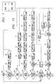
- Figure 6 is directed to an exhaust brake control system for use with a vehicle having an automatic transmission and a diesel engine.
- the sequence begins at the initial position 100.
- a first query checks 102 the state of the warm-up signal 66 from the main vehicle controller.
- the signal derived from the main vehicle controller indicating activation of the warm-up mode is recognized 104 and the actuator 24 is commanded 106 to assume a partially closed position.
- the activation of the actuator 24 for the warm-up mode is independent of whether the exhaust brake system has been activated by the operator.
- the state of the power button is next sampled 108.
- a command 114 is given to fully open the butterfly valve 16.
- the torque converter clutch 13 is set 116 to normal and the transmission 12 is also set 118 to normal vehicle control. In this way all conditions are returned to the initial position 100.
- the power button of the user interface 69 is ON, the exhaust brake controls are activated under certain circumstances. The exhaust brake system is not to be employed when the accelerator has been applied.
- the accelerator sensor 62 is sensed 110 for its state of application. If the accelerator is applied, this is recognized 112 and a command 114 is given to fully open the butterfly valve 16.
- the torque converter clutch 13 is set 116 to normal vehicle control.
- the transmission 12 is also set 118 to normal vehicle control. This may also include an appropriate setting for an overdrive gear as well.
- the state of pressure within the exhaust system 11 between the internal combustion engine 10 and the exhaust brake 14 samples the pressure sensor 64 to determine 120 back pressure. If the pressure exceeds the preselected maximum amount, 60 psi in this case, the controller 50 is queried 122 to determine if the exhaust valve 16 has been commanded open. If so and if the back pressure is above the acceptable level, an indication is given 124 to the operator by means of a failure light. Further, given the apparent failure mode, the torque converter clutch 13 is set 116 to normal and the transmission 12 is set 118 to normal as well and the cycle returns to initial position 100. If the butterfly valve 16 is not open under the condition of excessive pressure, then a failure is not indicated and the exhaust brake 14 is commanded 126 to open by an incremental amount. Five percent is used in this embodiment. The cycle is then complete and the system returns to the initial position 100.
- the speed signal representative of the speed of the vehicle from the speed sensor 52 is sampled 128. If the vehicle is traveling at the preset speed set at the user interface 69, the cycle is complete and returns to the initial position 100.
- the vehicle speed sensor 52 is compared 130 to determine if the vehicle is traveling faster than or slower than the vehicle speed value input from the user interface 69. If the vehicle is not traveling faster than the preset speed value, the state of the valve 16 is sensed 132. If the butterfly valve 16 is not already commanded to be open, the valve 16 is opened 126 by a preset increment of five percent. The system then cycles back to the initial position 100 to initiate a new routine. If instead the valve 16 is already commanded to be open, the drive coupling sensor 54 is sampled 134 to determine the condition of the torque converter clutch 13.
- the torque converter clutch 13 is unlocked 136 and the routine recycles to the initial position 100. If the torque converter clutch 13 is not locked, the gear selection sensor 56 is checked 138. If the transmission 12 is not in high gear, the transmission 12 is commanded 138 to upshift 140 and the routine returns to the initial position 100. If the transmission 12 is already in high gear and the speed is below the set value and the torque converter clutch 13 is unlocked, a signal indicating a need for the application of the accelerator is given 142 to the operator. The routine then recycles back to the initial position 100.
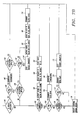
- the exhaust brake 14, the torque converter clutch 13 and the transmission 12 are put in states of providing less retarding of the vehicle.
- this too may be engaged under the right engine speed conditions to provide a less retarding state.
- the rate of speed change of the vehicle is determined 144.
- the state of the engine is sensed by looking to the engine speed sensor 60 to determine if the engine speed is slow enough that a downshift may be initiated 146.
- this engine speed is less than 2500 rpm.
- each engine and transmission assembly would dictate its own engine speed threshold.
- a downshift is commanded 148 of the transmission 12.
- the magnitude of the acceleration is then determined 150.
- the threshold magnitude of acceleration is set at 2 miles per hour per second.
- the routine returns to the initial position 100. If the acceleration is greater than the threshold level, the speed of the engine is determined by sampling the engine speed sensor 60 and comparing 152 the engine speed with a preset high speed value. In this embodiment, the preset high speed value is 2800 rpm. If the engine speed is below the high speed value, the torque converter clutch 13 is locked 154. Once the torque converter clutch 13 is locked 154, the butterfly valve 16 is commanded 156 to close. If the speed of the engine 10 is above the high speed value, the butterfly valve 16 is commanded 156 to be closed regardless of the state of the torque converter clutch 13 and the routine returns to the initial position 100. The command 156 to close the butterfly valve 16 with the preferred embodiment exhaust brake will fully shut off exhaust flow. Modulation based on the state of the pressure sensor 64 will prevent overpressure by opening the valve, steps 120, 122 and 126.
- the acceleration is compared 158 with the threshold for excessive acceleration. Again, two mph/second is employed in this embodiment. If the acceleration is too rapid, the speed of the engine is again sensed and compared 152 with the upper value of the speed range. As described above, there is a determination to either command 156 the closure of the butterfly valve 16 or first lock 154 the torque converter clutch and then command 156 the closure of the butterfly valve 16.
- the exhaust brake 14 is checked 160 to see if the butterfly valve 16 is fully closed. If not, the actuator 24 is commanded 162 to close the butterfly valve 16 by an increment to increase the exhaust brake application. In this embodiment, the increment has been established as five percent. If the exhaust brake 14 is already fully applied, the drive train is next turned to for increasing the braking effect of the engine.
- the speed of the engine is again sensed and compared 164 with the established standard for safe downshifting.
- the standard is 2500 rpm. If the speed is sufficiently low, the butterfly valve 16 is opened 166 and the transmission is commanded 168 to downshift. The routine then cycles to the initial position 100. If the engine speed is too high for downshifting, the status of the drive coupling sensor 54 is sensed 170. If the torque converter clutch 13 is not locked, the speed of the engine is again sensed 172. If the speed is no greater than the upper limit for locking the torque converter clutch 13, 2800 rpm in this example, the butterfly valve 16 is opened 174 and the torque converter clutch 13 is locked 176. The routine then recycles to the initial position 100.
- the torque converter clutch, the transmission and the exhaust brake are selectively controlled.
- the hierarchy of these controls depends on empirical vehicle dynamics.
- the controller 50 controls an intake valve actuator 76 which actuates a link 78 to open the valve independently of the accelerator linkage 80.
- the controller 50 also provides a signal to the fuel system to terminate fuel delivery upon activation of the exhaust brake 14.
- the intake throttle valve 74 may be the normal valve used to control the engine. However, it may also be a separate valve associated with the intake manifold to bypass the valve controlled by the accelerator pedal. The use of the term "intake throttle valve" is to be inclusive of either.
- the actuator 76 holding the intake throttle valve 74 open is deactivated 180 and fuel delivery is returned 182 to normal.
- This series of steps to disable all of the exhaust brake controls returns the vehicle to a power running condition. Even if the throttle is not applied but the back pressure in the manifold has exceeded the maximum limit and the valve is commanded open, the deactivation of the exhaust brake system and the inlet control is once again performed as with the applied throttle.
- the activator 76 for opening the intake throttle valve 74 is released 180 and the fuel delivery is returned 182 to normal.
- the activator 76 is activated 184 to hold the intake throttle valve 74 open for air flow into the engine and fuel delivery is cut off 186.
- the activator 76 opens 184 the intake throttle valve 74 and fuel is cut off 186. In these circumstances, the closure or partial closure of the butterfly valve 16 is enhanced in operation because the intake throttle valve 74 to the engine is opened.
- Figure 8 sets forth the schematic for an exhaust brake control system for a diesel type engine employing a manual transmission 12.
- the reference numbers may be compared with those of Figures 6 and 7 where the steps are to the same effect.
- the drive train includes a manual transmission 12
- no mechanism is provided for automatically actuating the drive coupling 13 or the transmission 12. Consequently, the system can only provide signals to the operator for upshifting and downshifting.
- a test 187 senses for an applied clutch, and if so the valve is opened 114. Consequently, the several steps found in the embodiment of Figure 6 to lock or unlock the drive coupling 13 are eliminated as are transmission shifts.
- the system will indicate 188 the need to upshift the transmission 12 if the transmission 12 is not yet in high gear.
- a light may be employed on the user interface 69 to convey that information to the operator.
- a downshift is indicated 190 if the engine is in a speed range low enough to accept the downshift.
- a downshift is indicated 190 by the user interface 69 when the speed of the engine is low enough to accommodate such a downshift.
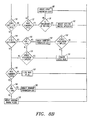
- Figure 9 which illustrates an exhaust brake control system for a gasoline-type engine having an intake throttle operating with a manual transmission
- the reference numerals reflect the same steps presented in the prior figures.
- the steps of activating or deactivating the inlet valve to the engine 184 and 180 and the initiation of fuel delivery 182 and the ceasing of fuel delivery 186 are employed at similar locations to that of Figure 7.
- the device of Figure 9 eliminates control of the drive coupling and of the transmission. Instead, indicator lights for upshifting 188 and downshifting 190 are employed.
- the rate at which the program cycles through the foregoing steps in any of these embodiments is advantageous in that rapid control, such as response to overpressure, can be achieved.
- the rate of cycling where, for example, valve closure is at a rate of 5% per cycle is too rapid.
- the perceived closure would be almost instantaneous. Consequently, delays are contemplated where the rate of change is preferably more moderate.
- the closure rate of the valve would be better performed at 20% per second rather than per cycle. At this rate, there would be four 5% closures per second. Going from fully open to fully closed would then take five seconds. Greater or lesser rates may be employed depending on such factors as driver perceptions and the magnitude of the braking needed. Therefore, additional steps delaying the initiation of valve adjustments and other actions where a specific rate of change is advantageous are contemplated to achieve improved drivability and system performance.
Landscapes
- Engineering & Computer Science (AREA)
- Chemical & Material Sciences (AREA)
- Combustion & Propulsion (AREA)
- Mechanical Engineering (AREA)
- Transportation (AREA)
- Automation & Control Theory (AREA)
- General Engineering & Computer Science (AREA)
- Control Of Throttle Valves Provided In The Intake System Or In The Exhaust System (AREA)
- Control Of Vehicle Engines Or Engines For Specific Uses (AREA)
Applications Claiming Priority (2)
| Application Number | Priority Date | Filing Date | Title |
|---|---|---|---|
| US09/287,975 US6152853A (en) | 1999-04-07 | 1999-04-07 | Vehicle exhaust brake and control system |
| US287975 | 1999-04-07 |
Publications (2)
| Publication Number | Publication Date |
|---|---|
| EP1043487A2 true EP1043487A2 (fr) | 2000-10-11 |
| EP1043487A3 EP1043487A3 (fr) | 2001-05-30 |
Family
ID=23105203
Family Applications (1)
| Application Number | Title | Priority Date | Filing Date |
|---|---|---|---|
| EP00107585A Withdrawn EP1043487A3 (fr) | 1999-04-07 | 2000-04-07 | Frein d'échappement pour véhicule et son système de commande |
Country Status (3)
| Country | Link |
|---|---|
| US (1) | US6152853A (fr) |
| EP (1) | EP1043487A3 (fr) |
| CA (1) | CA2303990C (fr) |
Cited By (5)
| Publication number | Priority date | Publication date | Assignee | Title |
|---|---|---|---|---|
| EP1302358A3 (fr) * | 2001-10-15 | 2004-04-14 | Isuzu Motors Limited | Contrôleur pour frein d'échappement |
| EP1390612A4 (fr) * | 2001-04-20 | 2005-12-07 | Jenara Entpr Ltd | Appareil et commande de frein sur echappement variable |
| WO2008121218A1 (fr) * | 2007-03-30 | 2008-10-09 | Caterpillar Inc. | Neutralisation d'embrayage de roue mettant en œuvre le système de vitesse de pointe de véhicule |
| EP2612015A4 (fr) * | 2010-08-31 | 2016-06-15 | Scania Cv Ab | Procédé de commande d'un registre permettant de réguler un flux dans un tuyau raccordé à un moteur |
| CN112524237A (zh) * | 2020-10-21 | 2021-03-19 | 中国重汽集团大同齿轮有限公司 | 一种电控气动手自一体十档铝壳变速箱 |
Families Citing this family (21)
| Publication number | Priority date | Publication date | Assignee | Title |
|---|---|---|---|---|
| US6652414B1 (en) * | 2001-11-26 | 2003-11-25 | Banks, Iii Gale C. | Vehicle engine brake and control system |
| US7028793B2 (en) * | 2002-02-08 | 2006-04-18 | Green Vision Technology, Llc | Internal combustion engines for hybrid powertrain |
| US20060086546A1 (en) * | 2002-02-08 | 2006-04-27 | Green Vision Technology, Llc | Internal combustion engines for hybrid power train |
| GB0203490D0 (en) * | 2002-02-14 | 2002-04-03 | Holset Engineering Co | Exhaust brake control system |
| US6782868B1 (en) * | 2003-03-10 | 2004-08-31 | Ford Global Technologies, Llc | Internal combustion engine having engine speed limit control system |
| US7509197B2 (en) * | 2005-01-31 | 2009-03-24 | Caterpillar Inc. | Retarding system implementing transmission control |
| US7322483B2 (en) * | 2005-08-31 | 2008-01-29 | Suncast Corporation | Cantilever shelving for utility shed |
| US7517300B2 (en) | 2005-10-31 | 2009-04-14 | Caterpillar Inc. | Retarding system implementing torque converter lockup |
| USD561078S1 (en) | 2005-11-18 | 2008-02-05 | Workhorse Custom Chassis, Llc | Vehicle header |
| USD561079S1 (en) | 2005-11-18 | 2008-02-05 | Workhorse Custom Chassis, Llc | Vehicle header |
| EP2446132A4 (fr) * | 2009-06-25 | 2013-07-17 | Int Engine Intellectual Prop | Soupape de frein pour freinage moteur |
| US8612106B2 (en) | 2010-10-20 | 2013-12-17 | GM Global Technology Operations LLC | System and method for controlling a transmission to improve exhaust braking |
| US9043102B2 (en) * | 2010-10-26 | 2015-05-26 | Fca Us Llc | Brake assist function |
| CN102128064A (zh) * | 2011-03-29 | 2011-07-20 | 刘冬生 | 车用发动机制动系统及其控制电路 |
| US8424507B2 (en) | 2011-08-31 | 2013-04-23 | Caterpillar Inc. | Retarding system |
| KR101509936B1 (ko) * | 2013-10-11 | 2015-04-07 | 현대자동차주식회사 | 고 출력 차량 배기 브레이크 및 이의 제어 방법 |
| SE542472C2 (en) * | 2016-06-22 | 2020-05-19 | Scania Cv Ab | Method for controlling an internal combustion engine experienceing uncontrolled behavior in a vehicle |
| US20200088082A1 (en) * | 2018-09-13 | 2020-03-19 | GM Global Technology Operations LLC | Exhaust system and method of operating the same |
| US10801417B1 (en) * | 2019-07-12 | 2020-10-13 | GM Global Technology Operations LLC | Methods and systems for regulating exhaust gas flow |
| CN111680363B (zh) * | 2020-06-09 | 2023-04-18 | 南方天合底盘系统有限公司 | 一种用于浮动式鼓式制动器行车制动效能因数的计算方法 |
| CN114013422B (zh) * | 2021-10-31 | 2023-05-30 | 东风商用车有限公司 | 车载发动机的辅助制动系统、方法和车辆 |
Citations (1)
| Publication number | Priority date | Publication date | Assignee | Title |
|---|---|---|---|---|
| US5193657A (en) * | 1991-03-07 | 1993-03-16 | Jatco Corporation | Exhaust braking control apparatus |
Family Cites Families (21)
| Publication number | Priority date | Publication date | Assignee | Title |
|---|---|---|---|---|
| JPS5828414B2 (ja) * | 1975-06-11 | 1983-06-15 | アイシンセイキ カブシキガイシヤ | エキゾ−ストブレ−キセイギヨソウチ |
| JPS6056896B2 (ja) * | 1980-03-07 | 1985-12-12 | マツダ株式会社 | エンジンの吸気装置 |
| JPS6128727A (ja) * | 1984-07-17 | 1986-02-08 | Nippon Denso Co Ltd | 車両用内燃機関の機関回転数制御装置 |
| JP2530306B2 (ja) * | 1985-05-08 | 1996-09-04 | アイシン精機株式会社 | エキゾ−ストブレ−キ制御装置 |
| JPS63135644A (ja) * | 1986-11-27 | 1988-06-08 | Japan Autom Transmission Co Ltd | 自動変速機の制御装置 |
| DE3866018D1 (de) * | 1987-05-22 | 1991-12-12 | Isuzu Motors Ltd | Motorbremssystem. |
| JPH02236056A (ja) * | 1988-04-22 | 1990-09-18 | Kobe Steel Ltd | 車両の制動装置 |
| JP2877344B2 (ja) * | 1989-04-19 | 1999-03-31 | 株式会社エクセディ | 車輌のエンジンブレーキ制御装置 |
| JP2791371B2 (ja) * | 1989-11-08 | 1998-08-27 | アイシン精機株式会社 | 車両用リターディング装置 |
| JP2973210B2 (ja) * | 1989-11-28 | 1999-11-08 | アイシン精機株式会社 | 車両用リターディング装置 |
| DE4024572C2 (de) * | 1990-08-02 | 1994-11-10 | Kloeckner Humboldt Deutz Ag | Registeraufladung für Brennkraftmaschinen in Nutzfahrzeugen |
| US5282399A (en) * | 1991-03-25 | 1994-02-01 | Jatco Corporation | Control system for vehicular power plant including automatic transmission and exhaust brake |
| US5425689A (en) * | 1992-07-06 | 1995-06-20 | Eaton Corporation | Engine brake enhanced upshift control method/system |
| US5315899A (en) * | 1992-11-09 | 1994-05-31 | Jatco Corporation | Hydraulic control system for automatic transmission of automotive vehicle with exhaust braking system using vehicle payload sensing means |
| SE502150C2 (sv) * | 1993-12-30 | 1995-09-04 | Saab Scania Ab | Förfarande och anordning för adaptivt frånslag av avgasbroms i samband med uppväxling |
| SE502550C2 (sv) * | 1994-03-18 | 1995-11-13 | Saab Scania Ab | Förfarande och anordning för bränslemängdsreglering i samband med nerväxling |
| US5699767A (en) * | 1994-04-28 | 1997-12-23 | Nissan Diesel Motor Co., Ltd. | Gas engine |
| JP3471149B2 (ja) * | 1995-10-11 | 2003-11-25 | ジヤトコ株式会社 | 補助ブレーキ装置 |
| JP3284857B2 (ja) * | 1995-10-31 | 2002-05-20 | アイシン精機株式会社 | 自動変速機の制御装置 |
| JPH09256885A (ja) * | 1996-03-22 | 1997-09-30 | Honda Motor Co Ltd | 車両の発電制御装置 |
| JPH1038067A (ja) * | 1996-07-18 | 1998-02-13 | Toyota Motor Corp | 車両の制御装置 |
-
1999
- 1999-04-07 US US09/287,975 patent/US6152853A/en not_active Expired - Lifetime
-
2000
- 2000-04-06 CA CA002303990A patent/CA2303990C/fr not_active Expired - Lifetime
- 2000-04-07 EP EP00107585A patent/EP1043487A3/fr not_active Withdrawn
Patent Citations (1)
| Publication number | Priority date | Publication date | Assignee | Title |
|---|---|---|---|---|
| US5193657A (en) * | 1991-03-07 | 1993-03-16 | Jatco Corporation | Exhaust braking control apparatus |
Cited By (8)
| Publication number | Priority date | Publication date | Assignee | Title |
|---|---|---|---|---|
| EP1390612A4 (fr) * | 2001-04-20 | 2005-12-07 | Jenara Entpr Ltd | Appareil et commande de frein sur echappement variable |
| EP1302358A3 (fr) * | 2001-10-15 | 2004-04-14 | Isuzu Motors Limited | Contrôleur pour frein d'échappement |
| WO2008121218A1 (fr) * | 2007-03-30 | 2008-10-09 | Caterpillar Inc. | Neutralisation d'embrayage de roue mettant en œuvre le système de vitesse de pointe de véhicule |
| US8012061B2 (en) | 2007-03-30 | 2011-09-06 | Caterpillar Inc. | Vehicle overspeed system implementing impeller clutch lockout |
| US8409054B2 (en) | 2007-03-30 | 2013-04-02 | Caterpillar Inc. | Vehicle overspeed system implementing impeller clutch lockout |
| EP2612015A4 (fr) * | 2010-08-31 | 2016-06-15 | Scania Cv Ab | Procédé de commande d'un registre permettant de réguler un flux dans un tuyau raccordé à un moteur |
| CN112524237A (zh) * | 2020-10-21 | 2021-03-19 | 中国重汽集团大同齿轮有限公司 | 一种电控气动手自一体十档铝壳变速箱 |
| CN112524237B (zh) * | 2020-10-21 | 2022-06-03 | 中国重汽集团大同齿轮有限公司 | 一种电控气动手自一体十档铝壳变速箱 |
Also Published As
| Publication number | Publication date |
|---|---|
| EP1043487A3 (fr) | 2001-05-30 |
| CA2303990A1 (fr) | 2000-10-07 |
| US6152853A (en) | 2000-11-28 |
| CA2303990C (fr) | 2007-08-21 |
Similar Documents
| Publication | Publication Date | Title |
|---|---|---|
| US6152853A (en) | Vehicle exhaust brake and control system | |
| US6652414B1 (en) | Vehicle engine brake and control system | |
| US5819538A (en) | Turbocharged engine system with recirculation and supplemental air supply | |
| US6178371B1 (en) | Vehicle speed control system and method | |
| US4951627A (en) | Engine idling speed control system for internal combustion engine | |
| US6979280B2 (en) | Control apparatus and control method for vehicle | |
| US5391127A (en) | Control apparatus in a motor vehicle for controlling a throttle valve on the base of actuation of an accelerator pedal and intake air quantity | |
| EP0659992A2 (fr) | Système et méthode pour contrôler un moteur à combustion interne | |
| KR920000369B1 (ko) | 차량용 자동변속장치 | |
| US5435795A (en) | Vehicle drivetrain control including CVT | |
| EP0557367B1 (fr) | Soupape de modulation pour pression des gaz d'echappement | |
| US6311118B1 (en) | Vehicle speed control system | |
| JPH05301535A (ja) | パワートレイン制御装置 | |
| KR19980701607A (ko) | 엔진 제어 시스템의 에러에 의존하는 제어 시스템(Control system dependent on an error in the engine control system) | |
| JP3149559B2 (ja) | ロックアップクラッチのスリップ制御装置 | |
| JPH0450551A (ja) | 無段変速機の変速比制御装置 | |
| JPS6233093B2 (fr) | ||
| JPS61232932A (ja) | 自動変速装置の変速制御方法 | |
| JP2891019B2 (ja) | 車両の駆動力制御装置 | |
| KR100285456B1 (ko) | 댐퍼 클러치 작동 쇼크 방지 장치 및 그 방법 | |
| JP2570379B2 (ja) | ガスタービンエンジン車両の変速制御装置 | |
| JPS5918121Y2 (ja) | 自動車のスロツトルバルブ制御装置 | |
| KR0184958B1 (ko) | 정속주행 엑셀레이터 제어장치 | |
| KR100270544B1 (ko) | 변속시 변속충격 완화장치 | |
| KR0142595B1 (ko) | 터보차저 장착 차량의 엔진브레이크장치 |
Legal Events
| Date | Code | Title | Description |
|---|---|---|---|
| PUAI | Public reference made under article 153(3) epc to a published international application that has entered the european phase |
Free format text: ORIGINAL CODE: 0009012 |
|
| AK | Designated contracting states |
Kind code of ref document: A2 Designated state(s): DE FR GB IT |
|
| AX | Request for extension of the european patent |
Free format text: AL;LT;LV;MK;RO;SI |
|
| PUAL | Search report despatched |
Free format text: ORIGINAL CODE: 0009013 |
|
| AK | Designated contracting states |
Kind code of ref document: A3 Designated state(s): AT BE CH CY DE DK ES FI FR GB GR IE IT LI LU MC NL PT SE |
|
| AX | Request for extension of the european patent |
Free format text: AL;LT;LV;MK;RO;SI |
|
| RIC1 | Information provided on ipc code assigned before grant |
Free format text: 7F 02D 9/06 A, 7F 02D 29/02 B, 7B 60K 41/26 B |
|
| 17P | Request for examination filed |
Effective date: 20011127 |
|
| AKX | Designation fees paid |
Free format text: DE FR GB IT |
|
| 17Q | First examination report despatched |
Effective date: 20030708 |
|
| 17Q | First examination report despatched |
Effective date: 20030708 |
|
| GRAP | Despatch of communication of intention to grant a patent |
Free format text: ORIGINAL CODE: EPIDOSNIGR1 |
|
| RIC1 | Information provided on ipc code assigned before grant |
Ipc: F02D 29/02 20060101ALI20070110BHEP Ipc: B60W 10/10 20060101ALI20070110BHEP Ipc: B60W 30/18 20060101ALI20070110BHEP Ipc: F02D 9/06 20060101AFI20070110BHEP Ipc: B60W 10/18 20060101ALI20070110BHEP |
|
| STAA | Information on the status of an ep patent application or granted ep patent |
Free format text: STATUS: THE APPLICATION IS DEEMED TO BE WITHDRAWN |
|
| 18D | Application deemed to be withdrawn |
Effective date: 20070425 |