EP1049082A2 - Méthode de commande de positionnement pour dispositif de stockage optique - Google Patents
Méthode de commande de positionnement pour dispositif de stockage optique Download PDFInfo
- Publication number
- EP1049082A2 EP1049082A2 EP00107597A EP00107597A EP1049082A2 EP 1049082 A2 EP1049082 A2 EP 1049082A2 EP 00107597 A EP00107597 A EP 00107597A EP 00107597 A EP00107597 A EP 00107597A EP 1049082 A2 EP1049082 A2 EP 1049082A2
- Authority
- EP
- European Patent Office
- Prior art keywords
- track
- dsp
- target position
- seek
- positioner
- Prior art date
- Legal status (The legal status is an assumption and is not a legal conclusion. Google has not performed a legal analysis and makes no representation as to the accuracy of the status listed.)
- Withdrawn
Links
Images










Classifications
-
- G—PHYSICS
- G11—INFORMATION STORAGE
- G11B—INFORMATION STORAGE BASED ON RELATIVE MOVEMENT BETWEEN RECORD CARRIER AND TRANSDUCER
- G11B7/00—Recording or reproducing by optical means, e.g. recording using a thermal beam of optical radiation by modifying optical properties or the physical structure, reproducing using an optical beam at lower power by sensing optical properties; Record carriers therefor
- G11B7/08—Disposition or mounting of heads or light sources relatively to record carriers
- G11B7/085—Disposition or mounting of heads or light sources relatively to record carriers with provision for moving the light beam into, or out of, its operative position or across tracks, otherwise than during the transducing operation, e.g. for adjustment or preliminary positioning or track change or selection
- G11B7/08505—Methods for track change, selection or preliminary positioning by moving the head
- G11B7/08517—Methods for track change, selection or preliminary positioning by moving the head with tracking pull-in only
-
- G—PHYSICS
- G11—INFORMATION STORAGE
- G11B—INFORMATION STORAGE BASED ON RELATIVE MOVEMENT BETWEEN RECORD CARRIER AND TRANSDUCER
- G11B21/00—Head arrangements not specific to the method of recording or reproducing
- G11B21/02—Driving or moving of heads
- G11B21/08—Track changing or selecting during transducing operation
- G11B21/081—Access to indexed tracks or parts of continuous track
- G11B21/083—Access to indexed tracks or parts of continuous track on discs
- G11B21/085—Access to indexed tracks or parts of continuous track on discs with track following of accessed part
-
- G—PHYSICS
- G11—INFORMATION STORAGE
- G11B—INFORMATION STORAGE BASED ON RELATIVE MOVEMENT BETWEEN RECORD CARRIER AND TRANSDUCER
- G11B7/00—Recording or reproducing by optical means, e.g. recording using a thermal beam of optical radiation by modifying optical properties or the physical structure, reproducing using an optical beam at lower power by sensing optical properties; Record carriers therefor
- G11B7/08—Disposition or mounting of heads or light sources relatively to record carriers
- G11B7/085—Disposition or mounting of heads or light sources relatively to record carriers with provision for moving the light beam into, or out of, its operative position or across tracks, otherwise than during the transducing operation, e.g. for adjustment or preliminary positioning or track change or selection
- G11B7/08505—Methods for track change, selection or preliminary positioning by moving the head
- G11B7/08529—Methods and circuits to control the velocity of the head as it traverses the tracks
-
- G—PHYSICS
- G11—INFORMATION STORAGE
- G11B—INFORMATION STORAGE BASED ON RELATIVE MOVEMENT BETWEEN RECORD CARRIER AND TRANSDUCER
- G11B7/00—Recording or reproducing by optical means, e.g. recording using a thermal beam of optical radiation by modifying optical properties or the physical structure, reproducing using an optical beam at lower power by sensing optical properties; Record carriers therefor
- G11B7/08—Disposition or mounting of heads or light sources relatively to record carriers
- G11B7/085—Disposition or mounting of heads or light sources relatively to record carriers with provision for moving the light beam into, or out of, its operative position or across tracks, otherwise than during the transducing operation, e.g. for adjustment or preliminary positioning or track change or selection
- G11B7/08505—Methods for track change, selection or preliminary positioning by moving the head
- G11B7/08541—Methods for track change, selection or preliminary positioning by moving the head involving track counting to determine position
-
- G—PHYSICS
- G11—INFORMATION STORAGE
- G11B—INFORMATION STORAGE BASED ON RELATIVE MOVEMENT BETWEEN RECORD CARRIER AND TRANSDUCER
- G11B7/00—Recording or reproducing by optical means, e.g. recording using a thermal beam of optical radiation by modifying optical properties or the physical structure, reproducing using an optical beam at lower power by sensing optical properties; Record carriers therefor
- G11B7/08—Disposition or mounting of heads or light sources relatively to record carriers
- G11B7/09—Disposition or mounting of heads or light sources relatively to record carriers with provision for moving the light beam or focus plane for the purpose of maintaining alignment of the light beam relative to the record carrier during transducing operation, e.g. to compensate for surface irregularities of the latter or for track following
- G11B7/0901—Disposition or mounting of heads or light sources relatively to record carriers with provision for moving the light beam or focus plane for the purpose of maintaining alignment of the light beam relative to the record carrier during transducing operation, e.g. to compensate for surface irregularities of the latter or for track following for track following only
Definitions
- the present invention relates generally to a seek control method in an optical storage device, of seek-moving a light beam to a target track on an optical storage medium and, more particularly, to a seek control method in an optical storage device using a digital signal processor.
- An optical storage device such as an optical disk device, an optical card device, etc. has been widely utilized as a storage device.
- an optical storage medium is irradiated with light beams, and data are thus written to and read from the optical storage medium.
- a so-called seek operation of moving the light beam to a desired track is conducted.
- a track error signal is generated by the light beam reflected from the optical storage medium in order to detect a position of the light beam.
- a track zero-cross signal TZC is obtained by slicing the track error signal at a zero level, and the present position is detected by counting those track zero-cross signals.
- a frequency of the track error signal TES during the seek is as high as 500 kHz at a maximum velocity. For this reason, it may happen that a one-sample process extends 10 or more tracks at a sampling frequency of 50 kHz - 40 kHz of the digital servo. Further, the track error signal TES during the seek has a smaller amplitude with an increase in moving velocity.
- the seek velocity if the seek velocity is high, the present position can be stably detected. If the seek velocity is low, however, a problem is that an exact position is hard to detect because of the velocity being unstable.
- feedforward quantities in accelerating and decelerating directions are applied to an acceleration period and a deceleration period as well.
- the present position is detected from the track error signal at each sample timing. Then, after calculating a target position at that sample timing, a target velocity and a real velocity are to be calculated.
- an error quantity between the target velocity and the real velocity is calculated. Furthermore, there is decided whether or not the detected present position is at a predetermined start-of-acceleration point or start-of-deceleration point. Then, if at the predetermined start-of-point, the feedforward quantity in the acceleration or deceleration direction is generated. This feedforward quantity is added to the above error quantity, thus obtaining a control quantity. Based on this control quantity, a motor for an optical head moving mechanism is driven.
- the motor for this head moving mechanism actualizes a high-velocity seek and therefore requires a large torque. For this reason, a coil of the motor has a large inductance component. Consequently, an actual current of the motor is late to start flowing. Therefore, the real velocity has a time-lag deviating from a target velocity curve.
- the time-lag is produced in the target velocity curve during a period from a timing of giving a start-of-acceleration indication or a start-of-deceleration indication to a time when the feedforward quantity is outputted.
- the control is performed to compensate a delay of an actual start of the deceleration, resulting in an increased error quantity. That is, an overshoot quantity augments.
- the servo system is thereby made unstable. Therefore, according to the prior art, it is difficult to locate the light beam to the target track.
- control is effected to compensate a delay of an actual start of the acceleration, and hence the error quantity augments, resulting in an increased overshoot quantity. hence, according to the prior art, constant velocity control is hard to perform.
- a seek control method in an optical storage device of seek-moving a light beam of an optical head from a certain track on an optical storage medium to a desired track.
- the seek control method comprises a step of calculating a target position and a step of detecting a present position from a track error signal indicating a relative position between the light beam and the track.
- the seek control method also comprises a step of calculating such a feedback control quantity as to zeroize an error between the target position and the present position and a step of a controlling moving mechanism for moving the light beam in accordance with the feedback control quantity.
- the present position detecting step includes a first present position detecting step of detecting the present position from a signal into which the track error signal is D/A-converted when a velocity of the light beam is low and a second present position detecting step of detecting the present position from a count value obtained by counting track zero-cross signals acquired by slicing the track error signal at a zero level when the velocity of the light beam is high.
- the present position is detected from an analog value of a track error signal TES.
- the track error signal TES has a sufficiently large amplitude, and hence, the accurate present position can be detected from the analog value of the track error signal TES.
- the present position is detected from a count value of track zero-cross signals obtained from the track error signal.
- the track error signal TES has a small amplitude. Therefore, the present position is detected from the count value, whereby the accurate present position can be detected.
- a seek control method in an optical storage device of seek-moving a light beam of an optical head from a certain track on an optical storage medium to a desired track.
- the seek control method comprises a step of generating a target velocity along a target velocity curve to reach the desired track from a certain track and a step of detecting a real velocity of the optical head from a track error signal of the optical head.
- the seek control method further comprises a step of calculating an error value between the target velocity and the real velocity, a step of generating a feedforward value before a change in acceleration of the target velocity in the target velocity curve occurs, a step of calculating a control value by adding the feedforward value to the error value and a step of driving a moving mechanism for moving the optical head in accordance with the control value.
- the feedforward value is generated before the change in the acceleration of the target velocity in the target velocity is caused. It is therefore possible to reduce the error quantity when applying the feedforward. Accordingly, it is feasible to prevent an occurrence of the overshoot of the error quantity and perform the stable high-velocity seek.
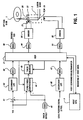
- FIG. 1 is a block diagram illustrating one embodiment of the present invention.
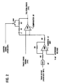
- FIG. 2 is a circuit diagram of a zero-cross comparator having a construction of FIG. 1.
- FIG. 3 is a circuit diagram of a track counter circuit having a construction of FIG. 2. Referring to FIG. 1, there is omitted a servo construction of a focus system that is not related to a track access.
- An optical disk 1 is irradiated with laser beams from an optical head (referred to as a positioner) 2. Data are thereby read and written.
- the optical head 2 includes an objective lens 20 for irradiating the disk 1 with the laser beams and a track actuator 21 for moving the objective lens 20 in directions across the tracks on the optical disk 1.
- the optical head 2 also includes a lens position detector 22 for detecting a position of the objective lens 20.
- a VCM (voice coil motor) 23 moves the optical head 2 in the directions across the tracks on the optical disk 1.
- a DSP (digital signal processor) 3 performs processing with a sample timer interrupt on the order of 40 kHz - 50 kHz. Then, the DSP 3 samples a track error signal TES during an on-track state and obtains a position error from a track center, thereby producing a control quantity. Similarly, during a seek process, as will hereinafter be explained with reference to FIG. 4A and subsequent drawings, a control quantity is produced based on the track error signal TES.
- a host MPU (microprocessor) 5 issues a host command such as a seek command, etc. to the DSP 3 and transfers host data about a seek difference, etc..
- a first digital/analog converter 40 converts a track offset value given from the host MPU 5 into an analog quantity.
- An adder 41 adds an output (track offset quantity) of the first D/A converter 40 to the track error signal TES.
- a secondary low-pass filter 42 is an analog low-pass filter for cutting off a high-frequency component of the track error signal TES.
- a cut-off frequency thereof is set at 20 kHz.
- the first analog/digital converter 43 converts the analog track error signal TES from the low-pass filter 42 into a digital value.
- the track error signal TES is a known signal obtained from an unillustrated divided-by-4 detector of the optical head 2.
- This track error signal TES is a signal taking a one-period sine wave for every track traverse.
- a zero-cross comparator (zero-cross circuit ) 44 as illustrated in FIG. 2, generates a track zero-cross signal TZC by slicing the track error signal TES with a reference voltage.
- a track counter circuit 45 detects a position of a light beam from the track zero-cross signal TZC.
- a secondary low-pass filter 46 is an analog low-pass filter for cutting off a high-frequency component of a lens position signal LPOS transmitted from the lens position detector 22.
- a second analog/digital converter 47 converts the analog lens position signal LPOS from the low-pass filter 46 into a digital value.
- a second digital/analog converter 48 converts a pseudo track error signal from the DSP 3 into an analog quantity.
- This pseudo track error signal is a signal obtained by the DSP 3 adding a predetermined gain to the track error signal inputted from the first A/D converter 43.
- the track offset value is controlled by monitoring this pseudo track error signal so that the value shows a symmetry between the upper and lower halves.
- a third digital/analog converter 49 converts an actuator control value given from the DSP 3 into an analog quantity.
- a drive circuit 50 drives the actuator 21 by an output of the third D/A converter 49.
- a fourth digital/analog converter 51 converts a VCM control value from the DSP 3 into an analog quantity.
- a drive circuit 52 drives the motor VCM 23 by an output of the fourth D/A converter 51.
- a summing amplifier 53 subtracts, from the reference voltage, the track offset quantity given from the first D/A converter 40.
- the track error signal TES is a signal centered on the reference voltage Vref but contains a DC component of the circuit offset. etc.. Therefore, the DC component is compensated by a pre-measured track offset value.
- R3, R4 and R5 are resistances.
- a comparator 54 compares the track error signal TES with the compensated reference voltage from the summing amplifier 53 and outputs a track zero-cross signal TZC.
- the digital voltage after being sliced is positive-fed back to this comparator 54 via the resistances R, R1 and a capacitor C.
- a hysteresis characteristic is thereby given to the comparator 54 and thus made insensitive to noises.
- the noises such as noises of a beard configuration by ID of the track, etc. contained in the track error signals TES are thereby eliminated.
- a feedback quantity thereof is set variable by turning ON/OFF a switch SW1 provided on a positive feedback route.
- the switch SW1 is turned ON to increase the feedback quantity. A malfunction due to the noises is thereby prevented.
- the switch SW1 is turned OFF to reduce the feedback quantity. The control thereof is carried out so that the zero-cross of the track error signal TES can be surely detected.
- the control of the switch SW1 is performed from the DSP 3.
- the DSP 3 turns OFF the switch SW1 when the velocity is over a fiducial velocity on the basis of a velocity detection which will be mentioned later.
- a zero-cross pulse generation circuit 60 generates edge pulses by synchronizing the track zero-cross signal TZC with a system clock.
- a latch pulse generation circuit 61 generates a latch pulse from a latch signal.
- An interval counter 62 measures an interval of the edge pulses (track zero-cross signal TZC) by counting the system clocks.
- An interval latch circuit 63 latches an output of the interval counter 62 in accordance with the edge pulses.
- a data holding latch circuit 64 holds data of the latch circuit 63 by use of the latch pulses.
- An output of this latch circuit 64 indicates a latest zero-cross interval value A. Then, and output of the latch circuit 64 is outputted to the DSP 3.
- a load pulse generation circuit 65 generates a load pulse in accordance with a load (write) signal from the DSP 3.
- An inverter 66 inverts a target number of tracks, which is given from the DSP 3.
- Loaded into a traverse track counter 67 is an inversion signal (target-number-of-tracks' complement) of the target number of tracks in accordance with the load pulse. Then, the traverse track counter 67 counts the edge pulses from a load value thereof.
- Data holding latch circuit 68 latches a count value of the interval counter 62 in accordance with the latch pulse. An output of this latch circuit 68 indicates a count value B from the latest zero-cross to a present time (when the latch pulse is generated). An output of this latch circuit 68 is outputted to the DSP 3.
- a data holding latch circuit 69 latches a count value of the traverse track counter 67 in accordance with the latch pulse. An output of this latch circuit 69 represents a number-of-remaining-tracks Xr. An output of this latch circuit 69 is outputted to the DSP 3.
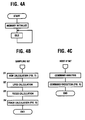
- FIGS. 4A, 4B and 4C are diagrams each illustrating firmware of the DSP 3.
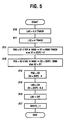
- FIG. 5 is a seek command processing flowchart in FIG. 4C.
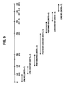
- FIG. 6 is an explanatory diagram of the seek process.
- the DSP 3 initializes the storage and comes into an idle status. In the idle status, if there is an interrupt, an interrupt process is executed.
- sampling interrupt process shown in FIG. 4B is executed. This sampling interrupt process will be described.
- the DSP 3 executes an LPOS calculation process of calculating a control quantity of a lens position. For instance, when lens is locked, a lens position signal LPOS from the second A/D converter 47 is sampled, and a relative position between the optical head 2 and the lens is obtained. Calculated subsequently is such a control quantity as to zeroize a position error obtained from the lens position signal LPOS. Based on this control quantity, the track actuator 21 is controlled through the D/A converter 49 and the drive circuit 50 as well. With this process, the optical head 2 is controlled so that the lens 20 is positioned at the center.
- the DSP 3 carries out a focus calculation process of calculating a control quantity of a focus position.
- a host interface interrupt process shown in FIG. 4C is carried out. In this interrupt process, a command is analyzed and then executed.
- the DSP 3 upon receiving the seek command, a seek difference and a seek direction, sets an end-of-acceleration track position LAE of the lens.
- the position LAE is predetermined on a [0.3] track.
- the DSP 3 sets an end-of-constant-velocity track position LCE of the lens.
- the position LCE is predetermined on a [4] track.
- the DSP 3 sets an end-of-acceleration track position PAE of a positioner 2 to X1.
- This value X1 is, if a difference DIF is over 6000 tracks, set to [3000] tracks. On the other hand, if the difference DIF does not exceed 6000 tracks, there is set such as [DIF] ⁇ 2.
- the DSP 3 sets an end-of-constant-velocity track position PCE of the positioner 2 to X2.
- This value X2 is, if the difference DIF is over 6000 tracks, set on ([DIF] - 3000) tracks. Whereas if the difference DIF does not exceed 6000 tracks, X1 is set.
- the DSP 3 sets an end-of-deceleration track position PBE of the positioner 2 to X3.
- the value X3 is ([DIF] - 4) tracks.
- the DSP 3 sets an end-of-constant-velocity track position LBS of the lens to X4.
- This value X4 is ([DIF] - 0.3) tracks.
- a seek processing mode to a target track is determined by this seek command process. As illustrated in FIG. 6, a lens acceleration period extends from a track [0] to a track LAE (0.3). A seek status signal SKSTS thereof is [1].
- a lens constant velocity period extends from a track LAE to a track LCE (4).
- the seek status signal SKSTS thereof is [2].
- the seek status signal SKSTS thereof is [3].
- the seek status signal SKSTS thereof is [4].
- the seek status signal SKSTS thereof is [5].
- the seek status signal SKSTS thereof is [6].
- a lens deceleration period extends from a track LBS to a track LBE.
- the seek status signal SKSTS thereof is [7]. Note that when the seek status signal SKSTS is [0], this indicates a fine control mode during the on-track status.
- These seek status signals SKSTS are stored in a register. Thus, each of the acceleration period, the constant velocity period and the deceleration period is set based on the seek difference.
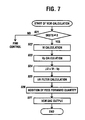
- FIG. 7 is a flowchart of a VCM calculation process in FIG. 4B.
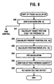
- FIG. 8 is a flowchart of a track calculation process in FIG. 4B.
- FIG. 9 is a flowchart of an SKSTS determination process in FIG. 8.
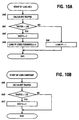
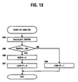
- FIGS. 10A through 13 are flowcharts of a target position calculation process in FIG. 8.
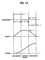
- FIG. 14 is an explanatory diagram of the target position calculation process.
- the DSP 3 checks whether or not the seek status signal SKSTS is [0]. If the seek status signal SKSTS is nothing but [0], that is, if the seek status signal SKSTS is just [0], this implies a fine control status, and hence the fine control is carried out.
- the track error signal TES is sampled from the analog/digital converter 43, and a position error from the track center is to be obtained. Then, there is calculated such a control quantity that this position error is zeroized, and the track actuator 21 is thereby controlled.
- the DSP 3 calculates a target velocity Vt.
- the target velocity Vt is given by [Target Position in Sampling Interrupt of Last Time] - [Target Position in Sampling Interrupt of This Time]. These target positions are obtained by the track calculation process in FIG. 8.
- the DSP 3 calculates a present velocity Vp.
- the present velocity Vp is given by [Present Position in Sampling Interrupt of Last Time] - [Present Position in Sampling Interrupt of This Time]. This present position is obtained by the track calculation process in FIG. 8.
- the DSP 3 performs a low-pass filter (iiR filter) calculation, thereby obtaining a control quantity.
- the DSP 3 adds, when the VCM feedforward flag is ON ([1]), a feedforward quantity to the obtained control quantity.
- This feedforward quantity is an acceleration quantity ⁇ .
- the DSP 3 decides the seek status signal SKSTS by processing in FIG. 9, which will be stated later. If the seek status signal SKSTS is [0], this implies the fine control status, and hence, as described above, the ON-track control is carried out.
- the DSP 3 next calculates the position error.
- a position error POSERR is obtained by a calculation such as [Target Position] - [Present Position].
- the DSP 3 adds, when the lens feedforward flag is ON ([1]), the feedforward quantity to the obtained control quantity.
- This feedforward quantity is the acceleration quantity ⁇ .
- the SKSTS deciding process is, as explained in FIG. 6, a process of deciding a seek status in accordance with the seek status signal SKSTS. That is, if the seek status signal SKSTS is [0], this implies a fine control status. If the seek status signal SKSTS is [1], this is a lens acceleration control status.
- the seek status signal SKSTS is [2], this is a lens constant velocity control status. If the seek status signal SKSTS is [3], this is a positioner acceleration control status. If the seek status signal SKSTS is [4], this is a positioner constant velocity control status. If the seek status signal SKSTS is [5], this is a positioner deceleration control status.
- the seek status signal SKSTS is [6] this is the lens constant velocity control status. If the seek status signal SKSTS is [7], this is a lens deceleration control status.
- the target position calculation process in the lens acceleration status will be explained with reference to FIG. 10A.
- the DSP 3 calculates the target position TAGPOS.
- the constant velocity period is a period for which the acceleration is zero.
- the DSP 3 checks whether or not the target position TAGPOS exceeds the lens constant velocity end track position LCE. The DSP 3, if the target position TAGPOS is not over the lens constant velocity end track position LCE, finishes the processing.
- the DSP 3 checks whether or not the target position TAGPOS exceeds the positioner acceleration end track position PAE.
- the DSP 3 calculates the target position TAGPOS.
- the constant velocity period is the period for which the acceleration is zero.
- the DSP 3 checks whether or not the target position TAGPOS exceeds the positioner constant velocity end track position PCE. The DSP 3, if the target position TAGPOS is not over the positioner constant velocity end track position PCE, finishes the processing.
- the DSP 3 checks whether or not the target position TAGPOS exceeds the positioner deceleration end track position PBE.
- the DSP 3 calculates the target position TAGPOS.
- the constant velocity period is the period for which the acceleration is zero.
- the DSP 3 checks whether or not the target position TAGPOS exceeds the lens constant velocity end track position LBE. The DSP 3, if the target position TAGPOS is not over the lens constant velocity end track position LBE, finishes the processing.
- the DSP 3 checks whether or not the target position TAGPOS exceeds the lens deceleration end track position LBE.
- FIG. 15 is a flowchart showing a present position calculation process in FIG. 8.
- FIG. 16 is a flowchart showing a process of calculation from the analog value.
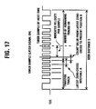
- FIGS. 17 and 18 are explanatory diagram each showing the present position calculation process.
- the DSP 3 checks whether the seek status signal SKSTS is [3] (positioner acceleration status) or [4] (positioner constant velocity status) or [5] (positioner deceleration status).
- the DSP 3 obtains the latest zero-cross interval A and a count value B from the latest zero-cross to the present one.
- FIG. 17 shows a relation ship between the latest zero-cross interval A and the count value B from the latest zero-cross to the present one. Then, the intra one-track position is given by B/A.
- the DSP 3 samples a digital value of the track error signal TES from the first analog/digital converter 43. Next, the DSP 3, as shown in FIG. 16, calculates the intra one-track position from the above sample value.
- the DSP 3 calculates a present position. Hence, the DSP 3 obtains a number-of-remaining-tracks Xr of the latch circuit 69. Then, as illustrated in FIG. 17, the number-of-remaining-tracks Xr is subtracted from a seek distance (difference) D, thereby obtaining a number of traverse tracks. The intra one-track position is added to this value, thus calculating the present position. Thus, the present position calculation process is finished.
- a resolution of the first A/D converter 43 is fully used for the sine wave track error signal TES.
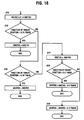
- the DSP 3 for normalization, obtains a digital value ADCTES by multiplying a digital value ADCTES of the sampled track error signal TES by a constant C.
- the DSP 3 checks whether or not a fraction of the target position calculated in FIGS. 10A through 13 does not exceed 0.25 track.
- the DSP 3 when deciding that the fraction of the target position is larger than 0.25 track, checks whether or not the fraction of the target position exceeds 0.75 track.
- the DSP 3 when deciding that the fraction of the target position is 0.25 track or more but does not exceed 0.75 tack, inverts a code of the digital value ADCTES to obtain -ADCTES.
- the DSP 3 checks whether or not the fraction of the target position exceeds 0.5.
- the fraction of the target position is in a range that does not exceed 0.25 track or in a range that exceeds 0.75 track, and this implies that the fraction of the target position falls within a range of ⁇ 0.25 track.
- the digital value of the track error signal TES can be used as it is.
- the code of the digital value of the track error signal is inverted. Then, when the fraction of the target position exceeds 0.5 track (i.e., when the intra one-track target position is between -0.25 track and -0.5 track), a value for 0.5 track is subtracted from the track error signal ADCTES.
- the fraction of the target position does not exceed 0.5 track (that is, when the intra -one-track target position is between 0.25 track and 0.5 track)
- the value for 0.5 track is added to the track error signal ADCTES.
- the track error signal TES assumes the sine wave, and hence, as illustrated in FIG. 18, the accurate position can not be detected at a round portion (within X-range in the Figure) in the vicinity of the peak. If the feedback control is applied at this portion where the position can not be accurately detected, the control becomes unstable. For this reason, the control quantity is zeroized at this portion.
- FIG. 19 is a flowchart of the position error calculation process therefor.
- the DSP 3 checks whether or not the fraction of the target position TAGPOS exceeds (0.25 - X).
- X represents a length of a rounded interval in the vicinity of the above-mentioned peak but is a range that does not exceed 0.25 track.
- the DSP 3 when deciding that the fraction of the target position TAGPOS exceeds (0.25 - X), checks whether or not the fraction of the target position TAGPOS exceeds (0.25 + X). If the fraction of the target position TAGPOS does not exceed (0.25 + X), the fraction of the target position is in a range of (0.25 - X) through (0.25 + X), and hence the position error POSERR is zeroized.
- the DSP 3 when deciding that the fraction of the target position exceeds (0.25 + X), checks whether or not the fraction of the target position TAGPOS exceeds (0.75 - X).
- the DSP 3 when deciding that the fraction of the target position TAGPOS exceeds (0.75 - X), checks whether or not the fraction of the target position TAGPOS exceeds (0.75 + X). If the fraction of the target position TAGPOS does not exceed (0.75 + X), the fraction of the target position is in a range of (0.75 - X) to (0.75 + X), and hence the position error POSERR is zeroized.
- the position error is calculated to be zero, thereby zeroizing the control quantity. The instability of the control is thus prevented.
- FIG. 20 is a processing flowchart of the modified embodiment of the position error calculation.
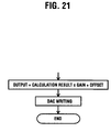
- FIG. 21 is a processing flowchart of an output of the actuator DAC.
- the DSP 3 calculates the position error POSERR by (Target Position TAGPOS - Present Position ADCPOS).
- the DSP 3 checks whether or not the fraction of the target position TAGPOS exceeds (0.25 - X).
- the DSP 3 when deciding that the fraction of the target position TAGPOS exceeds (0.25 - X), checks whether or not the fraction of the target position TAGPOS exceeds (0.25 + X). If the fraction of the target position TAGPOS does not exceed (0.25 + X), the fraction of the target position is in a range of (0.25 - X) through (0.25 + X), and hence the gain GAIN is set to [0], and the processing terminates.
- the DSP 3 when deciding that the fraction of the target position exceeds (0.25 + X), checks whether or not the fraction of the target position TAGPOS exceeds (0.75 - X). The DSP 3, when deciding that the fraction of the target position TAGPOS does not exceed (0.75 - X), sets the gain GAIN to [1]. Then, the processing comes to an end.
- the DSP 3 when deciding that the fraction of the target position TAGPOS exceeds (0.75 - X), checks whether or not the fraction of the target position TAGPOS exceeds (0.75 + X). If the fraction of the target position TAGPOS does not exceed (0.75 + X), the fraction of the target position is in a range of (0.75 - X) to (0.75 + X), and hence the gain GAIN is set to [0]. Then, the processing terminates.
- step S36 of FIG. 8 a result of calculating the output the actuator DAC in step S35 of FIG. 8 is multiplied by the gain GAIN described above. Further, an offset value is added, thus calculating the output. Subsequently, a result of this calculation is outputted (written) to the D/A converter 49 of the actuator.
- the gain is calculated to be zero, thereby zeroizing the control quantity. The instability of the control is thus prevented.
- FIG. 22 is a flowchart of the PID calculation process in FIG. 8.
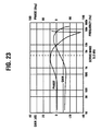
- FIG. 23 is an explanatory diagram showing the PID calculation process.
- the PID calculation is performed by use of parameters of such a compensation system as to sufficiently getting the phase allowance, counting on the reduction in gain during the seek.
- disPE1 dPE1 + disPE0 X Cds
- dPE1 the differential of the position error of this time
- disPE0 the differential term at the sampling of the last time during the seek control
- Cds the differential constant
- phase allowance is acquired during even the seek.
- the stability when the light beam reaches the target track is thereby enhanced.
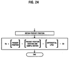
- FIG. 24 is a flowchart showing the modified embodiment of the calculation process of the present velocity of FIG. 7.
- a velocity signal obtained from the track counter 45 contains a relative velocity between the positioner 2 and the objective lens 20 in addition to the real velocity of the positioner (optical head) 2. It is therefore required that the relative velocity be subtracted from the velocity signal obtained.
- a signal corresponding to the relative velocity between the positioner 2 and the objective lens 20 is a differential value of the lens position signal LPOS. Accordingly, this differential value is subtracted from the velocity signal, thus obtaining a real velocity of the positioner.
- Vp Xp1 - Xp0 - dL ⁇ Gh
- Xp1 is the present position
- Xp0 is the present position one sample before
- dL is the differentiated lens position signal
- Gh is the normalized gain
- the real velocity of the positioner is obtained by subtracting the relative velocity between the positioner 2 and the objective lens 20 from the signal given out of the track counter 45.
- This differentiated lens position signal dL is calculated in the LPOS calculation process (step S3) shown in FIG. 4B. Therefore, this is easily actualized by diverting a result of this calculation.
- the feedforward control is effective as a method of preventing a delay of the control. As illustrated in FIGS. 7 and 8, the feedforward value on the occasion of the seek is given to each of the track actuator and the positioner in accordance with the seek status.
- That feedforward value is, in the case of the track actuator, a value corresponding to the acceleration ⁇ 1 used for the addition of the target position but is, in the case of the positioner, a value corresponding to the acceleration ⁇ 2 used for the calculation of the target velocity.
- the VCM 23 for moving the positioner requires a large torque. Therefore, a coil of the VCM 23 has a large inductance component. The current is late to start flowing, correspondingly. Then, in accordance with this embodiment, a timing when imparting the feedforward to the positioner is controlled faster than a timing at which the acceleration changes, thereby preventing the delay.
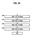
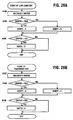
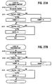
- FIG. 25 is a flowchart showing a modified embodiment of a seek command process therefor.
- FIGS. 26A through 27B are flowcharts showing a modified embodiment of the target position calculation process.
- FIG. 28 is an explanatory diagram of the seek process thereof.
- FIG. 29 is an explanatory diagram of the feedforward control thereof.
- FIG. 30 is an explanatory diagram showing how the feedforward operation operates.
- the processing in FIG. 25 is executed additionally after the seek command process explained in FIG. 5.
- the DSP 3 sets a positioner acceleration start track position PASF such as (Lens Constant Velocity End Track Position LCE - 0.5 Track). That is, the positioner acceleration start track position is the lens constant velocity end track position LCE, while the acceleration start track position is set 0.5 track anterior thereto.
- PASF Position Constant Velocity End Track Position LCE - 0.5 Track
- the DSP 3 sets a positioner acceleration end track position PAEF such as (Positioner Acceleration End Track Position PAE - 10 Tracks). That is, the positioner acceleration end track position (i.e., positioner constant velocity start track position) is PAE, while the acceleration end track position is set 10 tracks anterior thereto.
- PAEF Positioner Acceleration End Track Position PAE - 10 Tracks
- the DSP 3 sets the positioner deceleration start position PBSF such as (Positioner Constant Velocity End Position PCE - 10 Tracks). That is, for the positioner deceleration start track position in FIG. 5, the positioner deceleration start track position is set 10 tracks anterior thereto.
- PBSF Positioner Constant Velocity End Position PCE - 10 Tracks
- the DSP 3 sets the positioner deceleration end track position PBEF such as (Positioner Deceleration End Position PBE - 0.5 Track). That is, for the positioner deceleration end track position in Fig. 5, the positioner deceleration end track position is set 0.5 track anterior thereto.
- FIG. 28 illustrates the respective positions PASF, PAEF, PBSF and PBEF. That is, the feedforward value is applied before the starts of the acceleration interval and the deceleration interval as well. With respect to the acceleration interval and the deceleration interval, since the acceleration changes at a target velocity, the feedforward is started before the change in the acceleration at the target velocity.
- the VCM 23 for moving the positioner 2 needs a large torque. hence, the coil of the VCM 23 has a larger inductance. The current is late to start flowing, correspondingly. Further, when performing the sample servo control by use of the DSP 3, there is produced a delay due to the sampling process.
- the lens constant velocity process shown in FIG. 10B changes to a process shown in FIG. 26A; the positioner acceleration process shown in FIG. 11A changes to a process illustrated in FIG. 27A; and the positioner deceleration process shown in FIG. 12A varies to a process shown in FIG. 27B.
- the DSP 3 calculates the target position TAGPOS.
- the target position x at the constant velocity is given by the above formula (3), where ⁇ 1 is the acceleration, t is the time, and t1 is the acceleration end time.
- the DSP 3 checks whether or not the target position TAGPOS exceeds the positioner acceleration start track position PASF.
- the DSP 3_when deciding that the target position TAGPOS does not exceed the positioner acceleration start track position PASF this indicates that the feedforward start position is not yet reached,_therefore sets OFF ([0]) the VCM feedforward flag.
- the DSP 3 checks whether or not the target position TAGPOS exceeds the lens constant velocity end track position LCE. The DSP 3, if the target position TAGPOS is not over the lens constant velocity end track position LCE, finishes the processing. On the other hand, the DSP 3_if the target position TAGPOS is over the lens constant velocity end track position LCE, this indicates that it exceeds the lens constant velocity period_ therefore changes the seek status signal SKSTS to [3] (positioner acceleration status). Then, the processing comes to an end.
- the DSP 3 checks whether or not the target position TAGPOS exceeds the positioner acceleration end track position PAEF for the feedforward.
- the DSP 3_deciding that the target position TAGPOS does not exceed the positioner acceleration end track position PAEF this indicates that the feedforward end position is not yet reached_therefore sets ON ([1]) the VCM feedforward flag.
- the DSP 3 checks whether or not the target position TAGPOS exceeds the positioner acceleration end track position PAE.
- the DSP 3 checks whether or not the target position TAGPOS exceeds the positioner deceleration start track position PBSF.
- the DSP 3 checks whether or not the target position TAGPOS exceeds the positioner constant velocity end track position PCE. The DSP 3, if the target position TAGPOS is not over the positioner constant velocity end track position PCE, finishes the processing. On the other hand, the DSP 3_if the target position TAGPOS is over the positioner constant velocity end track position PCE, this indicates that it exceeds the positioner constant velocity period_ therefore changes the seek status signal SKSTS to [5] (positioner deceleration status). Then, the processing comes to an end.
- the DSP 3 checks whether or not the target position TAGPOS exceeds the positioner deceleration end track position PBEF for the feedforward.
- the DSP 3_deciding that the target position TAGPOS does not exceed the feedforward positioner deceleration end track position PBEF this indicates that the feedforward deceleration control period does note terminate_therefore sets ON ([1]) the VCM feedforward flag.
- the DSP 3 checks whether or not the target position TAGPOS exceeds the positioner deceleration end track position PBE.
- the start and end positions of the feedforward are calculated beforehand from the positions of the light beams, and hence the calculation process in the target position can be carried out at a high speed.
- the reason why the lens actuator is driven before driving the VCM 23 lies in preventing the light beams from traveling backward due to an eccentricity of the optical disk. Namely, the light beams are previously accelerated faster than an eccentric velocity of the optical disk. The seek operation can be thereby performed without undergoing an influence of the eccentricity of the light beams.
- the method of calculating the present position is changed by deciding the light beam velocity status from the seek status signal.
- the method of calculating the present position may be, however, changed by deciding the light beam velocity from the target velocity or the present velocity.
- the timing of applying the feedforward is controlled based on the position of the light beam. As illustrated in FIG. 30, however, the timing of applying the feedforward may be controlled based on the number of remaining samples.
- the timing of applying the feedforward for both of the acceleration and the deceleration is made fast.
- the application timing for one of the acceleration and the deceleration may also be, however, made fast.
- the optical disk may involve the use of a variety of writable and rewritable optical disks.
- the method of obtaining the present position from the track error signal changes in accordance with the velocity of the light beams, and, therefore, the optimum present position can be detected corresponding to the status of the track error signal, thereby actualizing the stable seek control.
- the timing of applying the feedforward is controlled before the acceleration change of the target velocity curve occurs. It is therefore possible to stabilize the system by reducing the error quantity when applying the feedforward.
Landscapes
- Moving Of The Head For Recording And Reproducing By Optical Means (AREA)
- Moving Of Head For Track Selection And Changing (AREA)
- Optical Recording Or Reproduction (AREA)
Applications Claiming Priority (5)
| Application Number | Priority Date | Filing Date | Title |
|---|---|---|---|
| JP06028095A JP3539785B2 (ja) | 1995-03-20 | 1995-03-20 | 光学記憶装置のシーク制御方法及び光学記憶装置 |
| JP6028095 | 1995-03-20 | ||
| JP23528295 | 1995-09-13 | ||
| JP23528295A JP3361662B2 (ja) | 1995-09-13 | 1995-09-13 | 光学記憶装置のシーク制御方法及び光学記憶装置 |
| EP96103752A EP0734016B1 (fr) | 1995-03-20 | 1996-03-10 | Méthode de commande de positionnement pour dispositif de stockage optique |
Related Parent Applications (1)
| Application Number | Title | Priority Date | Filing Date |
|---|---|---|---|
| EP96103752A Division EP0734016B1 (fr) | 1995-03-20 | 1996-03-10 | Méthode de commande de positionnement pour dispositif de stockage optique |
Publications (2)
| Publication Number | Publication Date |
|---|---|
| EP1049082A2 true EP1049082A2 (fr) | 2000-11-02 |
| EP1049082A3 EP1049082A3 (fr) | 2006-11-22 |
Family
ID=26401347
Family Applications (3)
| Application Number | Title | Priority Date | Filing Date |
|---|---|---|---|
| EP96103752A Expired - Lifetime EP0734016B1 (fr) | 1995-03-20 | 1996-03-10 | Méthode de commande de positionnement pour dispositif de stockage optique |
| EP00107597A Withdrawn EP1049082A3 (fr) | 1995-03-20 | 1996-03-10 | Méthode de commande de positionnement pour dispositif de stockage optique |
| EP00107558A Withdrawn EP1063643A3 (fr) | 1995-03-20 | 1996-03-10 | Méthode de commande de positionnement pour dispositif de stockage optique |
Family Applications Before (1)
| Application Number | Title | Priority Date | Filing Date |
|---|---|---|---|
| EP96103752A Expired - Lifetime EP0734016B1 (fr) | 1995-03-20 | 1996-03-10 | Méthode de commande de positionnement pour dispositif de stockage optique |
Family Applications After (1)
| Application Number | Title | Priority Date | Filing Date |
|---|---|---|---|
| EP00107558A Withdrawn EP1063643A3 (fr) | 1995-03-20 | 1996-03-10 | Méthode de commande de positionnement pour dispositif de stockage optique |
Country Status (3)
| Country | Link |
|---|---|
| US (4) | US5675562A (fr) |
| EP (3) | EP0734016B1 (fr) |
| DE (1) | DE69631082T2 (fr) |
Families Citing this family (16)
| Publication number | Priority date | Publication date | Assignee | Title |
|---|---|---|---|---|
| JPH09282816A (ja) * | 1996-04-05 | 1997-10-31 | Sony Corp | モータ制御装置、モータ制御方法及び光ディスク装置 |
| JPH09305984A (ja) * | 1996-05-20 | 1997-11-28 | Fujitsu Ltd | 光学的記憶装置 |
| TW386228B (en) * | 1998-02-27 | 2000-04-01 | Mediatek Inc | Tracking device for an optical pickup head |
| JP2000285479A (ja) * | 1999-03-31 | 2000-10-13 | Fujitsu Ltd | 情報記憶装置 |
| JP3530429B2 (ja) * | 1999-09-03 | 2004-05-24 | 三洋電機株式会社 | ディスク装置 |
| US6510019B1 (en) | 1999-11-12 | 2003-01-21 | Maxtor Corporation | Acceleration tracking position controller |
| TW513706B (en) * | 2000-03-08 | 2002-12-11 | Via Tech Inc | Track seeking and track locking method of optical disk |
| DE10064051A1 (de) * | 2000-12-21 | 2002-12-05 | Thomson Brandt Gmbh | Positionsregelung mittels Spurzählwert |
| US7023766B2 (en) * | 2001-01-25 | 2006-04-04 | Dphi Acquisitions, Inc. | Flexible servicing of servo algorithms using a digital signal processor |
| US7522480B2 (en) | 2001-01-25 | 2009-04-21 | Dphi Acquisitions, Inc. | Digital tracking servo system with multi-track seek with an acceleration clamp |
| KR100480627B1 (ko) * | 2002-11-09 | 2005-03-31 | 삼성전자주식회사 | 미러신호를 이용한 스핀들 모터의 등선속도 제어방법 및제어장치 |
| CN100405497C (zh) * | 2002-11-27 | 2008-07-23 | 皇家飞利浦电子股份有限公司 | 对探测头执行跳轨以从载体恢复数据的方法 |
| JP4389175B2 (ja) * | 2006-06-13 | 2009-12-24 | ソニー株式会社 | サーボ制御装置、サーボ制御方法、光ディスク装置及びビデオカメラレコーダ |
| US20080151709A1 (en) * | 2006-12-20 | 2008-06-26 | Hon Hai Precision Industry Co., Ltd. | Seeking method for optical disk drive |
| FR2922695A1 (fr) * | 2007-10-22 | 2009-04-24 | St Microelectronics Grenoble | Circuit de commande de moteur a bobine mobile |
| JP2011100500A (ja) * | 2009-11-04 | 2011-05-19 | Hitachi Consumer Electronics Co Ltd | 光ディスク装置およびトラッキング制御方法 |
Family Cites Families (46)
| Publication number | Priority date | Publication date | Assignee | Title |
|---|---|---|---|---|
| US4200827A (en) * | 1977-06-29 | 1980-04-29 | International Business Machines Corporation | Positioning system employing feedforward and feedback control |
| GB2039078B (en) * | 1978-12-27 | 1982-11-24 | Ibm | Sampled data servo positioning system |
| US4627038A (en) * | 1984-07-05 | 1986-12-02 | Storage Technology Partners Ii | Optical disk storage unit having a servo system with different velocity inputs |
| JPS6139239A (ja) * | 1984-07-28 | 1986-02-25 | Sony Corp | 光学式デイスクプレ−ヤ |
| JPS62110678A (ja) * | 1985-11-08 | 1987-05-21 | Matsushita Electric Ind Co Ltd | 光学式デイスク再生装置 |
| JPS62120675A (ja) * | 1985-11-20 | 1987-06-01 | Matsushita Electric Ind Co Ltd | 光学式デイスク再生装置 |
| JPS62185284A (ja) * | 1986-02-10 | 1987-08-13 | Matsushita Electric Ind Co Ltd | 光学式デイスク再生装置 |
| JPH0673188B2 (ja) * | 1986-03-31 | 1994-09-14 | 松下電器産業株式会社 | 光デイスクのアクセス装置 |
| JP2624651B2 (ja) * | 1986-07-21 | 1997-06-25 | 株式会社日立製作所 | 光スポット位置決め方法 |
| US5285431A (en) * | 1987-12-02 | 1994-02-08 | Mitsubishi Denki Kabushiki Kaisha | Information storage device with head position detection outside a user utilizable region and an optical disk drive device having target velocity-controlled head actuation |
| JP2543061B2 (ja) * | 1987-01-13 | 1996-10-16 | 松下電器産業株式会社 | 光ディスクのアクセス装置 |
| JPS63206977A (ja) * | 1987-02-24 | 1988-08-26 | Matsushita Electric Ind Co Ltd | 光学式記録再生装置 |
| JPH0783625B2 (ja) * | 1987-04-03 | 1995-09-06 | 三菱電機株式会社 | 検出ヘツドの速度制御装置 |
| JPH0654542B2 (ja) | 1987-08-28 | 1994-07-20 | 富士通株式会社 | 光学記憶装置 |
| US5077719A (en) | 1987-08-28 | 1991-12-31 | Fujitsu Limited | Optical disk access system |
| JPH0814945B2 (ja) * | 1988-04-06 | 1996-02-14 | 株式会社東芝 | 磁気ディスク装置の磁気ヘッド移動制御装置 |
| JP2573301B2 (ja) * | 1988-04-22 | 1997-01-22 | 株式会社東芝 | ディスク装置 |
| US5005089A (en) * | 1988-05-10 | 1991-04-02 | Quantum Corp. | High performance, high capacity micro-winchester disk drive |
| JP2732591B2 (ja) * | 1988-06-30 | 1998-03-30 | 株式会社東芝 | 記録媒体処理装置 |
| JP2756264B2 (ja) | 1988-08-12 | 1998-05-25 | 富士通株式会社 | 光学記憶装置 |
| JPH02230567A (ja) * | 1989-03-02 | 1990-09-12 | Olympus Optical Co Ltd | トラック検索制御装置 |
| JPH0760526B2 (ja) * | 1989-04-10 | 1995-06-28 | 富士通株式会社 | 光記憶装置のビーム移動速度測定方法とその装置 |
| US4972350A (en) * | 1989-05-26 | 1990-11-20 | Literal Corporation | Position mode track seek servo for high capacity disk drive system |
| JPH035975A (ja) * | 1989-06-01 | 1991-01-11 | Sony Corp | 光ディスクのシーク回路 |
| US4914725A (en) * | 1989-07-10 | 1990-04-03 | International Business Machines Corporation | Transducer positioning servo mechanisms employing digital and analog circuits |
| US5033039A (en) * | 1989-07-31 | 1991-07-16 | Literal Corporation | Positioning system for flexure mounted read/write head |
| US5050146A (en) * | 1989-07-31 | 1991-09-17 | Literal Corporation | Track seek recovery system and method |
| JP2672019B2 (ja) | 1989-08-15 | 1997-11-05 | 富士通株式会社 | 光ディスク装置 |
| JPH0782647B2 (ja) * | 1989-11-08 | 1995-09-06 | 富士通株式会社 | 光ディスク装置 |
| JP2657561B2 (ja) * | 1990-02-09 | 1997-09-24 | 富士通株式会社 | 位置決め制御方式 |
| JP2656371B2 (ja) * | 1990-06-26 | 1997-09-24 | 富士通株式会社 | 光ディスク装置 |
| JP3164580B2 (ja) * | 1990-09-27 | 2001-05-08 | 豊田工機株式会社 | ディジタルサーボ制御装置 |
| JP2751635B2 (ja) * | 1990-11-27 | 1998-05-18 | 松下電器産業株式会社 | 光ディスク装置 |
| JP2693281B2 (ja) * | 1991-03-19 | 1997-12-24 | 富士通株式会社 | 光ディスク装置のシーク制御方法及びその回路 |
| JP2987822B2 (ja) * | 1991-09-19 | 1999-12-06 | オリンパス光学工業株式会社 | アクセス制御装置 |
| JPH05120701A (ja) * | 1991-10-28 | 1993-05-18 | Ricoh Co Ltd | 光デイスクドライブ |
| JPH05159493A (ja) * | 1991-12-02 | 1993-06-25 | Seiko Epson Corp | トラックサーボ回路 |
| JPH0778891B2 (ja) * | 1991-12-25 | 1995-08-23 | インターナショナル・ビジネス・マシーンズ・コーポレイション | 光ディスク駆動装置および方法 |
| JP3626761B2 (ja) * | 1991-12-26 | 2005-03-09 | 松下電器産業株式会社 | 制御誤差生成装置 |
| JP2807118B2 (ja) | 1992-02-27 | 1998-10-08 | 富士通株式会社 | 光ディスク装置 |
| JP3152726B2 (ja) | 1992-03-31 | 2001-04-03 | 日本フエンオール株式会社 | 温度検知装置 |
| US5298447A (en) * | 1993-07-22 | 1994-03-29 | United Microelectronics Corporation | Method of fabricating a flash memory cell |
| JPH07262719A (ja) * | 1994-03-17 | 1995-10-13 | Fujitsu Ltd | ディスク装置 |
| US5585976A (en) * | 1994-06-22 | 1996-12-17 | Seagate Technology, Inc. | Digital sector servo incorporating repeatable run out tracking |
| JP3377013B2 (ja) * | 1994-08-18 | 2003-02-17 | 日本電信電話株式会社 | ディスク装置のシーク制御装置及びそれを用いたシーク制御方法 |
| US5576909A (en) * | 1995-02-16 | 1996-11-19 | Ministor Peripherals International Limited | Method for positioning a data transducer head in a rotating disk drive data storage device |
-
1996
- 1996-02-28 US US08/608,445 patent/US5675562A/en not_active Expired - Fee Related
- 1996-03-10 DE DE69631082T patent/DE69631082T2/de not_active Expired - Fee Related
- 1996-03-10 EP EP96103752A patent/EP0734016B1/fr not_active Expired - Lifetime
- 1996-03-10 EP EP00107597A patent/EP1049082A3/fr not_active Withdrawn
- 1996-03-10 EP EP00107558A patent/EP1063643A3/fr not_active Withdrawn
-
1997
- 1997-05-28 US US08/864,465 patent/US6055217A/en not_active Expired - Fee Related
-
1999
- 1999-08-24 US US09/382,430 patent/US6249497B1/en not_active Expired - Fee Related
-
2001
- 2001-05-07 US US09/850,282 patent/US6377523B2/en not_active Expired - Fee Related
Also Published As
| Publication number | Publication date |
|---|---|
| US6055217A (en) | 2000-04-25 |
| DE69631082T2 (de) | 2004-06-03 |
| EP1063643A2 (fr) | 2000-12-27 |
| DE69631082D1 (de) | 2004-01-29 |
| EP1063643A3 (fr) | 2006-11-22 |
| EP1049082A3 (fr) | 2006-11-22 |
| EP0734016B1 (fr) | 2003-12-17 |
| EP0734016A3 (fr) | 1996-11-20 |
| US5675562A (en) | 1997-10-07 |
| US20010019521A1 (en) | 2001-09-06 |
| US6377523B2 (en) | 2002-04-23 |
| EP0734016A2 (fr) | 1996-09-25 |
| US6249497B1 (en) | 2001-06-19 |
Similar Documents
| Publication | Publication Date | Title |
|---|---|---|
| EP0734016B1 (fr) | Méthode de commande de positionnement pour dispositif de stockage optique | |
| EP0745981B1 (fr) | Appareil et procédé d'enrigstrement/lecture optique d'information | |
| EP0502713B1 (fr) | Circuit pour la génération d'un signal de saut de piste pour appareil à disque optique pour la sortie correcte du signal de saut de piste et l'execution correcte et stable de l'opération de positionnement, même dans une région à haute vélocité du faisceau | |
| EP0422851B1 (fr) | Système de contrôle de décélération | |
| US5487055A (en) | Information recorder with tracking and seeking operations using low frequency tracking and lens position signals | |
| EP0505252B1 (fr) | Méthode et circuit pour la correction du signal de passage par zéro dans un système de disque optique | |
| EP0605239B1 (fr) | Appareil d'enregistrement et de reproduction de données | |
| US6266301B1 (en) | Optical storage device and optical head having TES compensation shift signal compensation | |
| EP0479475A2 (fr) | Appareil pour stockage sur disques | |
| KR0157606B1 (ko) | 시크 제어 장치 | |
| US5802019A (en) | Access control system for optical disk device | |
| JP3539785B2 (ja) | 光学記憶装置のシーク制御方法及び光学記憶装置 | |
| JP3749235B2 (ja) | 光学記憶装置のシーク制御方法及び光学記憶装置 | |
| JP3717490B2 (ja) | 光学記憶装置のシーク制御方法及び光学記憶装置 | |
| US5675563A (en) | Track access method and apparatus therefor | |
| JPH09167357A (ja) | 光学式記録再生装置におけるトラックジャンプ制御装置 | |
| JPH0536099A (ja) | 情報記録再生装置 | |
| JP3361662B2 (ja) | 光学記憶装置のシーク制御方法及び光学記憶装置 | |
| JP2777223B2 (ja) | 光ディスク装置 | |
| JPH0278023A (ja) | 光情報記憶装置 | |
| JPH06274903A (ja) | 光ヘッド制御装置 | |
| JP3352178B2 (ja) | 情報記録再生装置 | |
| JPH05266616A (ja) | トラックアクセス装置 | |
| JP2001084599A (ja) | 光ディスク装置 | |
| JPH0736127B2 (ja) | サーボ回路の位置制御切換制御方法 |
Legal Events
| Date | Code | Title | Description |
|---|---|---|---|
| PUAI | Public reference made under article 153(3) epc to a published international application that has entered the european phase |
Free format text: ORIGINAL CODE: 0009012 |
|
| 17P | Request for examination filed |
Effective date: 20000412 |
|
| AC | Divisional application: reference to earlier application |
Ref document number: 734016 Country of ref document: EP |
|
| AK | Designated contracting states |
Kind code of ref document: A2 Designated state(s): AT BE CH DE DK ES FI FR GB GR IE IT LI LU MC NL PT SE |
|
| AX | Request for extension of the european patent |
Free format text: AL;LT;LV;SI |
|
| PUAL | Search report despatched |
Free format text: ORIGINAL CODE: 0009013 |
|
| AK | Designated contracting states |
Kind code of ref document: A3 Designated state(s): AT BE CH DE DK ES FI FR GB GR IE IT LI LU MC NL PT SE |
|
| AX | Request for extension of the european patent |
Extension state: AL LT LV SI |
|
| AKX | Designation fees paid |
Designated state(s): DE FR GB |
|
| 17Q | First examination report despatched |
Effective date: 20071123 |
|
| RAP1 | Party data changed (applicant data changed or rights of an application transferred) |
Owner name: MATSUSHITA ELECTRIC INDUSTRIAL CO., LTD. |
|
| RAP1 | Party data changed (applicant data changed or rights of an application transferred) |
Owner name: PANASONIC CORPORATION |
|
| STAA | Information on the status of an ep patent application or granted ep patent |
Free format text: STATUS: THE APPLICATION HAS BEEN WITHDRAWN |
|
| 18W | Application withdrawn |
Effective date: 20081218 |