EP1052736A1 - Elektrisches Verbindersystem für Flachkabel - Google Patents
Elektrisches Verbindersystem für Flachkabel Download PDFInfo
- Publication number
- EP1052736A1 EP1052736A1 EP00401185A EP00401185A EP1052736A1 EP 1052736 A1 EP1052736 A1 EP 1052736A1 EP 00401185 A EP00401185 A EP 00401185A EP 00401185 A EP00401185 A EP 00401185A EP 1052736 A1 EP1052736 A1 EP 1052736A1
- Authority
- EP
- European Patent Office
- Prior art keywords
- conductors
- test
- tracks
- card
- ribbon
- Prior art date
- Legal status (The legal status is an assumption and is not a legal conclusion. Google has not performed a legal analysis and makes no representation as to the accuracy of the status listed.)
- Granted
Links
- 239000004020 conductor Substances 0.000 claims abstract description 24
- 238000004026 adhesive bonding Methods 0.000 description 3
- 238000012544 monitoring process Methods 0.000 description 2
- 238000003466 welding Methods 0.000 description 2
- 230000005540 biological transmission Effects 0.000 description 1
- 230000009849 deactivation Effects 0.000 description 1
- 230000007547 defect Effects 0.000 description 1
- 238000001514 detection method Methods 0.000 description 1
- 230000007257 malfunction Effects 0.000 description 1
- 229920006267 polyester film Polymers 0.000 description 1
- 229910000679 solder Inorganic materials 0.000 description 1
- 238000005476 soldering Methods 0.000 description 1
- XLYOFNOQVPJJNP-UHFFFAOYSA-N water Substances O XLYOFNOQVPJJNP-UHFFFAOYSA-N 0.000 description 1
Images
Classifications
-
- H—ELECTRICITY
- H01—ELECTRIC ELEMENTS
- H01R—ELECTRICALLY-CONDUCTIVE CONNECTIONS; STRUCTURAL ASSOCIATIONS OF A PLURALITY OF MUTUALLY-INSULATED ELECTRICAL CONNECTING ELEMENTS; COUPLING DEVICES; CURRENT COLLECTORS
- H01R13/00—Details of coupling devices of the kinds covered by groups H01R12/70 or H01R24/00 - H01R33/00
- H01R13/64—Means for preventing incorrect coupling
- H01R13/641—Means for preventing incorrect coupling by indicating incorrect coupling; by indicating correct or full engagement
-
- H—ELECTRICITY
- H01—ELECTRIC ELEMENTS
- H01R—ELECTRICALLY-CONDUCTIVE CONNECTIONS; STRUCTURAL ASSOCIATIONS OF A PLURALITY OF MUTUALLY-INSULATED ELECTRICAL CONNECTING ELEMENTS; COUPLING DEVICES; CURRENT COLLECTORS
- H01R12/00—Structural associations of a plurality of mutually-insulated electrical connecting elements, specially adapted for printed circuits, e.g. printed circuit boards [PCB], flat or ribbon cables, or like generally planar structures, e.g. terminal strips, terminal blocks; Coupling devices specially adapted for printed circuits, flat or ribbon cables, or like generally planar structures; Terminals specially adapted for contact with, or insertion into, printed circuits, flat or ribbon cables, or like generally planar structures
- H01R12/70—Coupling devices
- H01R12/77—Coupling devices for flexible printed circuits, flat or ribbon cables or like structures
- H01R12/79—Coupling devices for flexible printed circuits, flat or ribbon cables or like structures connecting to rigid printed circuits or like structures
-
- H—ELECTRICITY
- H05—ELECTRIC TECHNIQUES NOT OTHERWISE PROVIDED FOR
- H05K—PRINTED CIRCUITS; CASINGS OR CONSTRUCTIONAL DETAILS OF ELECTRIC APPARATUS; MANUFACTURE OF ASSEMBLAGES OF ELECTRICAL COMPONENTS
- H05K1/00—Printed circuits
- H05K1/02—Details
- H05K1/0266—Marks, test patterns or identification means
- H05K1/0268—Marks, test patterns or identification means for electrical inspection or testing
-
- H—ELECTRICITY
- H05—ELECTRIC TECHNIQUES NOT OTHERWISE PROVIDED FOR
- H05K—PRINTED CIRCUITS; CASINGS OR CONSTRUCTIONAL DETAILS OF ELECTRIC APPARATUS; MANUFACTURE OF ASSEMBLAGES OF ELECTRICAL COMPONENTS
- H05K1/00—Printed circuits
- H05K1/02—Details
- H05K1/14—Structural association of two or more printed circuits
- H05K1/148—Arrangements of two or more hingeably connected rigid printed circuit boards, i.e. connected by flexible means
-
- H—ELECTRICITY
- H05—ELECTRIC TECHNIQUES NOT OTHERWISE PROVIDED FOR
- H05K—PRINTED CIRCUITS; CASINGS OR CONSTRUCTIONAL DETAILS OF ELECTRIC APPARATUS; MANUFACTURE OF ASSEMBLAGES OF ELECTRICAL COMPONENTS
- H05K1/00—Printed circuits
- H05K1/02—Details
- H05K1/11—Printed elements for providing electric connections to or between printed circuits
- H05K1/117—Pads along the edge of rigid circuit boards, e.g. for pluggable connectors
-
- H—ELECTRICITY
- H05—ELECTRIC TECHNIQUES NOT OTHERWISE PROVIDED FOR
- H05K—PRINTED CIRCUITS; CASINGS OR CONSTRUCTIONAL DETAILS OF ELECTRIC APPARATUS; MANUFACTURE OF ASSEMBLAGES OF ELECTRICAL COMPONENTS
- H05K2201/00—Indexing scheme relating to printed circuits covered by H05K1/00
- H05K2201/03—Conductive materials
- H05K2201/0332—Structure of the conductor
- H05K2201/0388—Other aspects of conductors
- H05K2201/0397—Tab
-
- H—ELECTRICITY
- H05—ELECTRIC TECHNIQUES NOT OTHERWISE PROVIDED FOR
- H05K—PRINTED CIRCUITS; CASINGS OR CONSTRUCTIONAL DETAILS OF ELECTRIC APPARATUS; MANUFACTURE OF ASSEMBLAGES OF ELECTRICAL COMPONENTS
- H05K3/00—Apparatus or processes for manufacturing printed circuits
- H05K3/36—Assembling printed circuits with other printed circuits
- H05K3/361—Assembling flexible printed circuits with other printed circuits
- H05K3/363—Assembling flexible printed circuits with other printed circuits by soldering
Definitions
- the invention relates to flexible films or circuits of conductors. electrical cables used to connect two printed circuit boards or other electrical components of a device.
- the flexibility of the sheet allows, during handling, to move the cards connected to it.
- Each end of the conductor of the ribbon cable is electrically connected to a card track or connector terminal, usually by soldering.
- a card track or connector terminal usually by soldering.
- the end zone of the conductor ply is fixed, for example stuck flat on the card. The welds are therefore not used mechanical fixing.
- the present invention aims to facilitate the detection of such a situation.
- the invention relates to an electrical component provided with a flexible sheet of connecting conductors, characterized in that the cable has two continuity test conductors connected by the component.
- the component carries a track for connecting the ribbon test conductors.
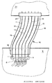
- the component of the invention is a circuit board 9 printed with a flexible sheet 10 of electrical conductors 11-16 to which it is mechanically and electrically connected. This is about conductive tracks printed on polyester film 19.
- the sheet 10 is flat at rest but it can naturally deform. Here it is connected, at its end opposite to the card 9, to a connector 20 intended to receive another printed circuit board 21 carrying electrical circuits. Mechanical connection to connector 20 is made by gluing to it or by pinching the tablecloth 10 therein.
- the card 9 has six welding zones 1 to 6 on which are welded the ends of the respective tracks 11 to 16.
- the side tracks 11 and 16 are shorter than the central tracks 12 to 15. Therefore, an end region 18 of the sheet 10 being glued flat on a zone, here lateral, of the map 9, the central ranges 2 to 5 are connected to connector 20 by central tracks 12-15 longer than the lateral tracks 11 and 16 located near the respective lateral edges of the tablecloth 10.
- Card 9 carries a track 8 which constitutes a loopback connection connecting one of tracks 11-16 to one of the others.
- the card 9, with the ribbon cable 10, thus comprises two test conductors continuity connected by card 9 and precisely by track 8.
- the remote card 21 includes a test circuit or member, not shown, connected, by connector 20, to the ends considered of tracks looped by their distant ends, here 11 and 16.
- the circuit of test checks the continuity of the loop formed by the two tracks 11 and 16, the loopback track 8 and the two welds of tracks 1 and 6. It this is for example a resistor in series with the input diode of a photocoupler, the assembly being supplied by a supply from the card 21, but through loop 11, 8, 16.
- the photocoupler activated, blocks a transistor or logic gate and its deactivation by opening the test loop triggers the transistor, which turns on a diode light-emitting fault indication. It can be expected that this transistor causes an interrupt request to a microprocessor, which can then signal the existence of the fault indicated, by display or transmission of information.
- the length of the central tracks 12-15 compared to the lateral tracks test 11 and 16 means that tracks 12-15 are not likely to be torn from the card 9, even if the ply 10 is folded down, then take off, on card 9, as long as the two side tracks 11 and 16 remain, at the end, both secured to the card 9.
- the mechanical fixing, between the sheet 10 of conductors and card 9 could be done other than by gluing, for example by pinching in a connector like the one referenced 20.
- the card 9 could be replaced by any other electrical component, by example a display or a relay.
- a tearing of the ribbon cable 10 at the connector 20 of the card 21 will also be detected.
- the monitoring or test circuit described more top, checking the continuity of the loop 11, 8, 16, could, alternatively, itself be arranged on the card 9. In such a case, this test circuit would remote feed, for example, the far ends of the side tracks 11 and 16, at the connector 20, through two of the central tracks 12-15, then looped back to this level (20) on the ends of tracks 11, 16 respective. More generally, we could constitute a sort coil with four test tracks, in series with the test members, with preferably at least one side track 11, 16 and even both 11, 16 like here.
Landscapes
- Engineering & Computer Science (AREA)
- Microelectronics & Electronic Packaging (AREA)
- Insulated Conductors (AREA)
- Testing Of Short-Circuits, Discontinuities, Leakage, Or Incorrect Line Connections (AREA)
- Printing Elements For Providing Electric Connections Between Printed Circuits (AREA)
- Combinations Of Printed Boards (AREA)
- Multi-Conductor Connections (AREA)
- Coupling Device And Connection With Printed Circuit (AREA)
Applications Claiming Priority (2)
| Application Number | Priority Date | Filing Date | Title |
|---|---|---|---|
| FR9905825A FR2793352B1 (fr) | 1999-05-07 | 1999-05-07 | Composant electrique a nappe souple de conducteurs de raccordement |
| FR9905825 | 1999-05-07 |
Publications (2)
| Publication Number | Publication Date |
|---|---|
| EP1052736A1 true EP1052736A1 (de) | 2000-11-15 |
| EP1052736B1 EP1052736B1 (de) | 2003-06-11 |
Family
ID=9545331
Family Applications (1)
| Application Number | Title | Priority Date | Filing Date |
|---|---|---|---|
| EP20000401185 Expired - Lifetime EP1052736B1 (de) | 1999-05-07 | 2000-04-28 | Elektrisches Verbindersystem für Flachkabel |
Country Status (6)
| Country | Link |
|---|---|
| US (1) | US6448508B1 (de) |
| EP (1) | EP1052736B1 (de) |
| JP (1) | JP4550222B2 (de) |
| DE (1) | DE60003261T2 (de) |
| ES (1) | ES2200798T3 (de) |
| FR (1) | FR2793352B1 (de) |
Cited By (1)
| Publication number | Priority date | Publication date | Assignee | Title |
|---|---|---|---|---|
| FR2915628A1 (fr) * | 2007-04-27 | 2008-10-31 | Valeo Systemes Thermiques | Dispositif electronique comportant deux composants electroniques relies entre eux par un connecteur souple |
Families Citing this family (13)
| Publication number | Priority date | Publication date | Assignee | Title |
|---|---|---|---|---|
| DE20210025U1 (de) * | 2002-06-25 | 2003-08-07 | Brose Fahrzeugteile GmbH & Co. KG, Coburg, 96450 Coburg | Flachleiter |
| KR100659826B1 (ko) * | 2005-12-20 | 2006-12-19 | 삼성에스디아이 주식회사 | 배터리 팩의 회로 기판 |
| JP2007335434A (ja) * | 2006-06-12 | 2007-12-27 | Nec Corp | フレキシブル配線基板、回路基板およびフレキシブル配線断線時の修復方法 |
| JP2008141139A (ja) * | 2006-12-05 | 2008-06-19 | Fujitsu Ltd | 電子機器、フレキシブル基板および基板固定部材 |
| TW200950222A (en) * | 2008-05-30 | 2009-12-01 | P Two Ind Inc | Connector device |
| US8118611B2 (en) * | 2008-10-31 | 2012-02-21 | Myoungsoo Jeon | PCB bridge connector for connecting PCB devices |
| US9633950B1 (en) | 2016-02-10 | 2017-04-25 | Qualcomm Incorporated | Integrated device comprising flexible connector between integrated circuit (IC) packages |
| US9633977B1 (en) | 2016-02-10 | 2017-04-25 | Qualcomm Incorporated | Integrated device comprising flexible connector between integrated circuit (IC) packages |
| CN109152206A (zh) * | 2018-08-24 | 2019-01-04 | 武汉恒泰通技术有限公司 | 一种避免焊盘对接不良的柔性软板及其装配夹具 |
| CN109068473A (zh) * | 2018-08-24 | 2018-12-21 | 武汉恒泰通技术有限公司 | 一种方便测试的柔性板及其装配系统 |
| CN109195306A (zh) * | 2018-08-24 | 2019-01-11 | 武汉恒泰通技术有限公司 | 一种测试良品率高的双面柔性软板及其装配夹具 |
| CN108834306A (zh) * | 2018-08-24 | 2018-11-16 | 武汉恒泰通技术有限公司 | 一种避免焊盘错位压配的柔性板及其装配系统 |
| CN108901128B (zh) * | 2018-08-26 | 2021-12-28 | 深圳华秋电子有限公司 | 双面柔性pcb板 |
Citations (3)
| Publication number | Priority date | Publication date | Assignee | Title |
|---|---|---|---|---|
| WO1994007318A1 (en) * | 1992-09-22 | 1994-03-31 | Icl Systems Ab | Termination arrangement at an interface at one end of the connectable and disconnectable multi-conductor cable |
| US5304987A (en) * | 1992-04-16 | 1994-04-19 | At&T Bell Laboratories | Board removal detection circuit |
| US5526217A (en) * | 1994-05-24 | 1996-06-11 | Intel Corporation | Voltage protection for modem add in cards with sideswipe contacts |
Family Cites Families (8)
| Publication number | Priority date | Publication date | Assignee | Title |
|---|---|---|---|---|
| JPS63111692A (ja) * | 1986-10-30 | 1988-05-16 | 日本電気ホームエレクトロニクス株式会社 | プリント基板 |
| JP2678327B2 (ja) * | 1991-02-15 | 1997-11-17 | 住友金属鉱山株式会社 | フレキシブル配線基板およびその製造方法 |
| JPH0685341B2 (ja) * | 1991-09-27 | 1994-10-26 | 帝国通信工業株式会社 | フレキシブル基板の端子構造 |
| JPH0837351A (ja) * | 1994-07-21 | 1996-02-06 | Amp Japan Ltd | フレキシブル回路板ハーネス装置及びそれに使用されるフレキシブル回路板 |
| JP2654762B2 (ja) * | 1994-11-22 | 1997-09-17 | セイコー電子工業株式会社 | 熱硬化性樹脂を含んだ異方性導電剤の圧着方法及び圧着機 |
| JP2606177B2 (ja) * | 1995-04-26 | 1997-04-30 | 日本電気株式会社 | 印刷配線板 |
| JPH10209594A (ja) * | 1997-01-17 | 1998-08-07 | Fuji Photo Optical Co Ltd | フレキシブルプリント回路基板と硬質プリント回路基板との接続構造 |
| JPH11167971A (ja) * | 1997-12-05 | 1999-06-22 | Olympus Optical Co Ltd | 電子機器 |
-
1999
- 1999-05-07 FR FR9905825A patent/FR2793352B1/fr not_active Expired - Fee Related
-
2000
- 2000-04-28 EP EP20000401185 patent/EP1052736B1/de not_active Expired - Lifetime
- 2000-04-28 DE DE60003261T patent/DE60003261T2/de not_active Expired - Lifetime
- 2000-04-28 ES ES00401185T patent/ES2200798T3/es not_active Expired - Lifetime
- 2000-05-04 US US09/564,480 patent/US6448508B1/en not_active Expired - Lifetime
- 2000-05-08 JP JP2000134742A patent/JP4550222B2/ja not_active Expired - Fee Related
Patent Citations (3)
| Publication number | Priority date | Publication date | Assignee | Title |
|---|---|---|---|---|
| US5304987A (en) * | 1992-04-16 | 1994-04-19 | At&T Bell Laboratories | Board removal detection circuit |
| WO1994007318A1 (en) * | 1992-09-22 | 1994-03-31 | Icl Systems Ab | Termination arrangement at an interface at one end of the connectable and disconnectable multi-conductor cable |
| US5526217A (en) * | 1994-05-24 | 1996-06-11 | Intel Corporation | Voltage protection for modem add in cards with sideswipe contacts |
Cited By (3)
| Publication number | Priority date | Publication date | Assignee | Title |
|---|---|---|---|---|
| FR2915628A1 (fr) * | 2007-04-27 | 2008-10-31 | Valeo Systemes Thermiques | Dispositif electronique comportant deux composants electroniques relies entre eux par un connecteur souple |
| WO2008135426A1 (fr) * | 2007-04-27 | 2008-11-13 | Valeo Systemes Thermiques | Dispositif électronique comportant deux composants électroniques reliés entre eux par un connecteur souple |
| US8210857B2 (en) | 2007-04-27 | 2012-07-03 | Valeo Systemes Thermiques | Electronic device including two electronic components connected together by a flexible connector |
Also Published As
| Publication number | Publication date |
|---|---|
| US6448508B1 (en) | 2002-09-10 |
| DE60003261T2 (de) | 2005-08-04 |
| DE60003261D1 (de) | 2003-07-17 |
| FR2793352A1 (fr) | 2000-11-10 |
| ES2200798T3 (es) | 2004-03-16 |
| JP2000349409A (ja) | 2000-12-15 |
| EP1052736B1 (de) | 2003-06-11 |
| JP4550222B2 (ja) | 2010-09-22 |
| FR2793352B1 (fr) | 2006-09-22 |
Similar Documents
| Publication | Publication Date | Title |
|---|---|---|
| EP1052736A1 (de) | Elektrisches Verbindersystem für Flachkabel | |
| US4514723A (en) | Method and apparatus for depicting inoperative electrical fuses | |
| US5428294A (en) | Reverse/forward bias tester for relay and diode packages | |
| EP2220916B8 (de) | Einrichtung zum schutz der anschlüsse einer elektronischen komponente | |
| JP2001337605A (ja) | 封印シール及び封印異常検出装置 | |
| US5101154A (en) | Open bond detector for an integrated circuit | |
| JP3398324B2 (ja) | 電線の電流検出センサおよびそれを用いた電流検出システム | |
| DE69316164D1 (de) | Prüfgerät für Steckdose mit Erdung und Differentialschutz | |
| JPS6367669B2 (de) | ||
| KR100476676B1 (ko) | 광섬유를 이용한 자동차 커넥터의 고장상태 점검장치 | |
| JPH10239373A (ja) | プリント配線基盤の部品実装時使用するショートチェッカー | |
| KR200171222Y1 (ko) | 단선진단회로삽입형정션박스 | |
| EP0521106A1 (de) | Antistatische sicherheitsvorrichtung | |
| JPH08148865A (ja) | 基板実装状態監視の配線構造 | |
| JP2988294B2 (ja) | ハーネスにおける導通検査方法 | |
| JPH05144885A (ja) | Tabテープ | |
| EP0167445A1 (de) | Anzeigevorrichtung mit, von einer Diodenmatrix, einzeln elektrisch steuerbaren Elementen | |
| JP2731896B2 (ja) | 光スイッチ装置 | |
| JPH0476583B2 (de) | ||
| JPH0714926Y2 (ja) | 半導体試験装置の波形入出力装置 | |
| JPH07264734A (ja) | 端子台試験装置 | |
| JP2590683Y2 (ja) | 電路監視ユニット | |
| Brumm | Printed structures- Optical inspection system for chip carriers | |
| JPS58195165A (ja) | コネクタ−抜け検出方法 | |
| JPS6366000B2 (de) |
Legal Events
| Date | Code | Title | Description |
|---|---|---|---|
| PUAI | Public reference made under article 153(3) epc to a published international application that has entered the european phase |
Free format text: ORIGINAL CODE: 0009012 |
|
| AK | Designated contracting states |
Kind code of ref document: A1 Designated state(s): DE ES FR GB IT |
|
| AX | Request for extension of the european patent |
Free format text: AL;LT;LV;MK;RO;SI |
|
| 17P | Request for examination filed |
Effective date: 20010510 |
|
| AKX | Designation fees paid |
Free format text: DE ES FR GB IT |
|
| 17Q | First examination report despatched |
Effective date: 20020715 |
|
| GRAH | Despatch of communication of intention to grant a patent |
Free format text: ORIGINAL CODE: EPIDOS IGRA |
|
| GRAH | Despatch of communication of intention to grant a patent |
Free format text: ORIGINAL CODE: EPIDOS IGRA |
|
| GRAA | (expected) grant |
Free format text: ORIGINAL CODE: 0009210 |
|
| AK | Designated contracting states |
Designated state(s): DE ES FR GB IT |
|
| REG | Reference to a national code |
Ref country code: GB Ref legal event code: FG4D Free format text: NOT ENGLISH |
|
| REF | Corresponds to: |
Ref document number: 60003261 Country of ref document: DE Date of ref document: 20030717 Kind code of ref document: P |
|
| RAP2 | Party data changed (patent owner data changed or rights of a patent transferred) |
Owner name: JOHNSON CONTROLS AUTOMOTIVE ELECTRONICS |
|
| GBT | Gb: translation of ep patent filed (gb section 77(6)(a)/1977) |
Effective date: 20031029 |
|
| REG | Reference to a national code |
Ref country code: ES Ref legal event code: FG2A Ref document number: 2200798 Country of ref document: ES Kind code of ref document: T3 |
|
| PLBE | No opposition filed within time limit |
Free format text: ORIGINAL CODE: 0009261 |
|
| STAA | Information on the status of an ep patent application or granted ep patent |
Free format text: STATUS: NO OPPOSITION FILED WITHIN TIME LIMIT |
|
| 26N | No opposition filed |
Effective date: 20040312 |
|
| REG | Reference to a national code |
Ref country code: FR Ref legal event code: PLFP Year of fee payment: 16 |
|
| REG | Reference to a national code |
Ref country code: FR Ref legal event code: PLFP Year of fee payment: 17 |
|
| REG | Reference to a national code |
Ref country code: FR Ref legal event code: PLFP Year of fee payment: 18 |
|
| PGFP | Annual fee paid to national office [announced via postgrant information from national office to epo] |
Ref country code: ES Payment date: 20170724 Year of fee payment: 18 Ref country code: FR Payment date: 20170713 Year of fee payment: 18 Ref country code: DE Payment date: 20170711 Year of fee payment: 18 Ref country code: IT Payment date: 20170724 Year of fee payment: 18 Ref country code: GB Payment date: 20170719 Year of fee payment: 18 |
|
| REG | Reference to a national code |
Ref country code: DE Ref legal event code: R119 Ref document number: 60003261 Country of ref document: DE |
|
| GBPC | Gb: european patent ceased through non-payment of renewal fee |
Effective date: 20180428 |
|
| PG25 | Lapsed in a contracting state [announced via postgrant information from national office to epo] |
Ref country code: DE Free format text: LAPSE BECAUSE OF NON-PAYMENT OF DUE FEES Effective date: 20181101 |
|
| PG25 | Lapsed in a contracting state [announced via postgrant information from national office to epo] |
Ref country code: GB Free format text: LAPSE BECAUSE OF NON-PAYMENT OF DUE FEES Effective date: 20180428 |
|
| PG25 | Lapsed in a contracting state [announced via postgrant information from national office to epo] |
Ref country code: FR Free format text: LAPSE BECAUSE OF NON-PAYMENT OF DUE FEES Effective date: 20180430 Ref country code: IT Free format text: LAPSE BECAUSE OF NON-PAYMENT OF DUE FEES Effective date: 20180428 |
|
| REG | Reference to a national code |
Ref country code: ES Ref legal event code: FD2A Effective date: 20190912 |
|
| PG25 | Lapsed in a contracting state [announced via postgrant information from national office to epo] |
Ref country code: ES Free format text: LAPSE BECAUSE OF NON-PAYMENT OF DUE FEES Effective date: 20180429 |