EP1059450A2 - Spiralverdichter - Google Patents
Spiralverdichter Download PDFInfo
- Publication number
- EP1059450A2 EP1059450A2 EP00111857A EP00111857A EP1059450A2 EP 1059450 A2 EP1059450 A2 EP 1059450A2 EP 00111857 A EP00111857 A EP 00111857A EP 00111857 A EP00111857 A EP 00111857A EP 1059450 A2 EP1059450 A2 EP 1059450A2
- Authority
- EP
- European Patent Office
- Prior art keywords
- low pressure
- working gas
- lubricating
- chamber
- lubricating oil
- Prior art date
- Legal status (The legal status is an assumption and is not a legal conclusion. Google has not performed a legal analysis and makes no representation as to the accuracy of the status listed.)
- Granted
Links
- 238000007789 sealing Methods 0.000 claims abstract description 69
- 239000000314 lubricant Substances 0.000 claims abstract description 37
- 238000005192 partition Methods 0.000 claims abstract description 16
- 239000010687 lubricating oil Substances 0.000 claims description 43
- CURLTUGMZLYLDI-UHFFFAOYSA-N Carbon dioxide Chemical compound O=C=O CURLTUGMZLYLDI-UHFFFAOYSA-N 0.000 claims description 41
- 229910002092 carbon dioxide Inorganic materials 0.000 claims description 37
- 239000001569 carbon dioxide Substances 0.000 claims description 37
- 239000003921 oil Substances 0.000 claims description 17
- 238000001816 cooling Methods 0.000 description 13
- 230000006835 compression Effects 0.000 description 7
- 238000007906 compression Methods 0.000 description 7
- 239000000470 constituent Substances 0.000 description 5
- 239000012071 phase Substances 0.000 description 5
- 230000001050 lubricating effect Effects 0.000 description 4
- 239000002826 coolant Substances 0.000 description 3
- 239000007788 liquid Substances 0.000 description 3
- 230000000149 penetrating effect Effects 0.000 description 3
- 238000004378 air conditioning Methods 0.000 description 2
- 239000003638 chemical reducing agent Substances 0.000 description 2
- 238000010276 construction Methods 0.000 description 2
- 238000010586 diagram Methods 0.000 description 2
- 238000001704 evaporation Methods 0.000 description 2
- 230000008020 evaporation Effects 0.000 description 2
- 230000002265 prevention Effects 0.000 description 2
- 229910000975 Carbon steel Inorganic materials 0.000 description 1
- 239000006096 absorbing agent Substances 0.000 description 1
- -1 and therefore Substances 0.000 description 1
- 238000005452 bending Methods 0.000 description 1
- 230000005540 biological transmission Effects 0.000 description 1
- 239000010962 carbon steel Substances 0.000 description 1
- 239000013013 elastic material Substances 0.000 description 1
- 229920001971 elastomer Polymers 0.000 description 1
- 230000008030 elimination Effects 0.000 description 1
- 238000003379 elimination reaction Methods 0.000 description 1
- 238000007667 floating Methods 0.000 description 1
- 239000012530 fluid Substances 0.000 description 1
- NBVXSUQYWXRMNV-UHFFFAOYSA-N fluoromethane Chemical compound FC NBVXSUQYWXRMNV-UHFFFAOYSA-N 0.000 description 1
- 239000007789 gas Substances 0.000 description 1
- 239000007791 liquid phase Substances 0.000 description 1
- 238000005461 lubrication Methods 0.000 description 1
- 239000000463 material Substances 0.000 description 1
- 238000012856 packing Methods 0.000 description 1
- 230000005855 radiation Effects 0.000 description 1
- 230000001105 regulatory effect Effects 0.000 description 1
- 239000005060 rubber Substances 0.000 description 1
- 229920003051 synthetic elastomer Polymers 0.000 description 1
- 239000005061 synthetic rubber Substances 0.000 description 1
- 238000009834 vaporization Methods 0.000 description 1
- 230000008016 vaporization Effects 0.000 description 1
Images


Classifications
-
- F—MECHANICAL ENGINEERING; LIGHTING; HEATING; WEAPONS; BLASTING
- F04—POSITIVE - DISPLACEMENT MACHINES FOR LIQUIDS; PUMPS FOR LIQUIDS OR ELASTIC FLUIDS
- F04C—ROTARY-PISTON, OR OSCILLATING-PISTON, POSITIVE-DISPLACEMENT MACHINES FOR LIQUIDS; ROTARY-PISTON, OR OSCILLATING-PISTON, POSITIVE-DISPLACEMENT PUMPS
- F04C18/00—Rotary-piston pumps specially adapted for elastic fluids
- F04C18/02—Rotary-piston pumps specially adapted for elastic fluids of arcuate-engagement type, i.e. with circular translatory movement of co-operating members, each member having the same number of teeth or tooth-equivalents
-
- F—MECHANICAL ENGINEERING; LIGHTING; HEATING; WEAPONS; BLASTING
- F04—POSITIVE - DISPLACEMENT MACHINES FOR LIQUIDS; PUMPS FOR LIQUIDS OR ELASTIC FLUIDS
- F04C—ROTARY-PISTON, OR OSCILLATING-PISTON, POSITIVE-DISPLACEMENT MACHINES FOR LIQUIDS; ROTARY-PISTON, OR OSCILLATING-PISTON, POSITIVE-DISPLACEMENT PUMPS
- F04C27/00—Sealing arrangements in rotary-piston pumps specially adapted for elastic fluids
- F04C27/008—Sealing arrangements in rotary-piston pumps specially adapted for elastic fluids for other than working fluid, i.e. the sealing arrangements are not between working chambers of the machine
- F04C27/009—Shaft sealings specially adapted for pumps
-
- Y—GENERAL TAGGING OF NEW TECHNOLOGICAL DEVELOPMENTS; GENERAL TAGGING OF CROSS-SECTIONAL TECHNOLOGIES SPANNING OVER SEVERAL SECTIONS OF THE IPC; TECHNICAL SUBJECTS COVERED BY FORMER USPC CROSS-REFERENCE ART COLLECTIONS [XRACs] AND DIGESTS
- Y10—TECHNICAL SUBJECTS COVERED BY FORMER USPC
- Y10S—TECHNICAL SUBJECTS COVERED BY FORMER USPC CROSS-REFERENCE ART COLLECTIONS [XRACs] AND DIGESTS
- Y10S418/00—Rotary expansible chamber devices
- Y10S418/01—Non-working fluid separation
Definitions
- the present invention relates to an open type compressor, and especially relates to an open type compressor which is suitable for a steam compression type cooling cycle using a coolant in the supercritical area of carbon dioxide (CO 2 ) and the like.
- CO 2 cycle which uses carbon dioxide (CO 2 ) as a working gas (coolant gas)
- a cooling cycle which uses carbon dioxide (CO 2 ) as a working gas (coolant gas) has been proposed for steam compression type cooling cycles, as a measures for elimination of fluorocarbons (refer to Japanese Patent Application, First Application No. Hei 7-18602, for example).
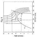
- the operation of this cooling cycle (hereinafter called CO 2 cycle) is similar to the conventional steam compression type cooling cycle. That is, as shown in a line A-B-C-D-A in Fig.
- gaseous CO 2 is compressing by a compressor (A-B), this gaseous CO 2 which is compressed at a high temperature is cooled by a radiator (gas cooler) (B-C), the pressure of the gas is reduced by a decompressor (C-D), the CO 2 which is changed to liquid phase is evaporated (D-A), and an external fluid such as air is cooled by the a latent heat of evaporation.
- the temperature of the CO 2 at the radiator side becomes higher than the critical temperature of CO 2 , because the critical temperature of CO 2 is about 31 °C which is lower than that of the fluorocarbons used as conventional coolants, and therefore, CO 2 does not condense at the radiator side (the line BC does not cross a saturation line SL in Fig. 6).
- the phase of CO 2 at the outlet side of the radiator (point C in Fig. 6) is determined by the exhaust pressure of the compressor and the CO 2 temperature at the outlet side of the radiator, and the CO 2 temperature at the outlet side of the radiator is determined by the radiation capacity of the radiator and the external temperature (which cannot be controlled).
- the temperature of CO 2 at the outlet side of the radiator is substantially uncontrollable, and the phase of the CO 2 at the outlet side of the radiator is controlled by the exhaust pressure of the compressor (the pressure at the outlet side of the radiator). Consequently, if the outer temperature is high during the summer season or the like, the pressure at the outlet side of the radiator must be increased as shown in line E-F-G-H-E in Fig. 6 to secure sufficient cooling capacity (difference in enthalpy), and the operation pressure of the compressor must be increased in comparison with the conventional compressor which uses fluorocarbons.
- the operation pressure of a compressor using CO 2 is increased to 40 kg/cm 2 , as opposed to that of a conventional compressor R134 using fluorocarbon, which is 3 kg/cm 2 .
- the stopping pressure of the compressor which using CO 2 is increased to 40 kg/cm 2 , as opposed to that of R134, which is 15 kg/cm 2 . Consequently, in the case of the CO 2 cycle, the differential pressure between the internal pressure of the compressor and the atmospheric pressure is increased, and therefore, there is concern of a gas leak from a shaft sealing portion of the compressor during the operation and stopping of the compressor.
- Japanese Patent Application, Second Publication No. Hei 3-6350 discloses a sealing apparatus for a shaft to seal a shaft-end portion of a screw type compressor.
- a mechanical seal and a plain bearing which acts as a labyrinth seal are separately arranged on the shaft-end portion to form an enclosed chamber between the seals.
- a lubricating material is sent into the chamber with a pressure which is higher than the pressure in a pump chamber, and gas leakage from the pump chamber is prevented.
- this apparatus is only for preventing the gas leakage during the operation, and is not for lubricating the machine room (pump chamber) of the compressor.
- the present invention is provided in compliance with the above problems of the conventional art, and the object of the present invention is to provide an open type compressor which can secure efficient and appropriate operation during the cooling cycle by Improving the lubrication ability during the operation and by preventing the leakage of the working gas when the operation is stopped.
- the open type compressor of the present invention provides the following features. That is, the open type compressor of the present invention is for compressing an introduced working gas and exhausting the working gas which is compressed by the predetermined pressure, and is characterized by comprising a crank case having a low pressure chamber in which the working gas is introduced, a crank shaft which is rotatively supported by the low pressure chamber by a bearing and compressing the working gas by rotation, a shaft seal which is provided on the crank shaft at the outer side of the bearing along the axial direction, a partition means which is provided between the bearing and the shaft seal for separating a space in which the shaft seal is provided from the low pressure chamber to form a sealing chamber, and a first lubricating agent supply passage which is formed in the crank case and is opened to the sealing chamber for supplying a lubricating agent to the sealing chamber.
- the highly compressed lubricating agent is filled in the sealing chamber which is partitioned by the partition means via the first lubricating agent supply passage at the operation of the compressor.
- the partition means is an non-contact type labyrinth seal.
- the labyrinth seal allows the leakage of a part of the highly compressed lubricating agent which is supplied from the sealing chamber to the low pressure chamber during the operation of the compressor.
- the desired leak capacity is provided by a gap between two constituent members which constitute the non-contact type seal.
- the pressure of the lubricating agent which is filled in the sealing chamber becomes sufficiently higher than that of the low pressure chamber (machine room).
- a contact type seal which is composed of a sealing apparatus such as a mechanical seal or shaft seal and a leak passage which is formed in the sealing apparatus can also be employed as the above-described partition means.
- a leak capacity similar to that of the above-described labyrinth seal can be obtained by forming a leak passage which provides a predetermined leak capacity to the contact-seal which has complete seal capacity.
- crank case has a second lubricating agent supply passage which is opened to the low pressure chamber for supplying the lubricating agent to the low pressure chamber.
- the lubricating agent is directly supplied to the low pressure chamber via this second lubricating agent supply passage during the operation.
- a lubricating oil supply means for supplying lubricating oil as a lubricating agent to the sealing chamber can also be provided.
- the lubricating oil supply means comprises an oil separator which is provided at an exhaust pipe of the highly compressed working gas for separating said lubricating oil from the working gas, and an oil return pipe for returning the lubricating oil which is separated by the oil separator to the first lubricating agent supply passage or first and second lubricating agent supply passages.
- the present invention is particularly effective for use in an open type compressor for a cooling cycle which uses carbon dioxide as the working gas in which the operation pressure is high and the working gas can easily be leaked.
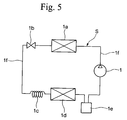
- This CO 2 cycle S is used for the air conditioning unit for a vehicle and reference number 1 denotes the open type compressor which compresses gaseous CO 2 .
- the open type compressor 1 is driven by a driving force which is supplied by a driving source, not shown (for example an engine or the like).
- Reference number 1a denotes a radiator (gas cooler) for cooling the CO 2 which is compressed by the open type compressor, by means of heat-exchange between the CO 2 and an external air;
- reference number 1b denotes a pressure regulation valve for regulating the pressure at the outlet side of the radiator 1a in compliance with the CO 2 temperature at the outlet side of the radiator 1a.
- the CO 2 which is decompressed by the pressure regulation valve 1b and a reducer 1c to forms 2 phases, gas and liquid, with low temperature and low pressure.
- Reference number 1d denotes an evaporator (heat absorber) which acts as a cooling means of the air in a passenger compartment, and the CO 2 which forms 2 phases of gas and liquid cools the air of inside the passenger compartment by taking the latent of vaporization (evaporation) of the CO 2 from the inside air, in the evaporator 1d.
- Reference number 1e denotes an accumulator for temporarily accumulating the liquid phased CO 2 .
- the open type compressor 1, radiator 1a, pressure regulation valve 1b, reducer 1c, evaporator 1d and accumulator 1e are connected by an oil exhaust pipe 1f and form a closed circuit.
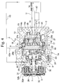
- a housing (casing) 1A of the open type compressor 1 is composed of a case main body 2 which has a cup shape, and a front case (crank case) 4 which is fastened the case main body 2 by a bolt 3.
- a crank shaft 5 penetrates the front case 4 and is rotatively supported in the front case 4 via a main bearing 6 and a sub bearing 7, and rotation of an automotive engine (not shown) is transmitted to the crank shaft via a known electromagnetic clutch 32.
- reference numbers 32a. 32b denote a coil and a pulley of the electromagnetic clutch 32 respectively.
- a fixed scroll 8 and revolving scroll 9 are provided in the housing 1A.
- the fixed scroll 8 has an end plate 10 and a spiral projection (lap) 11 which is projected from the inner surface of the end plate 10, and a backing block 13 is detachably fastened to the case main body 2 by a bolt 12.
- O-rings 14a, 14b are provided on inner and outer surfaces of the backing block 13 respectively. These O-rings 14a, 14b are closely contacted with the inner surface of the case main body 2, and therefore, a low pressure chamber (intake chamber) 15 which is formed in the case main body 2 and a high pressure chamber (exhaust chamber) 16 which is explained later are isolated.
- the high pressure chamber 16 is composed of an inner space 13a of the backing block 13 and a hollow portion 10a which is formed on the back surface of the end plate 10.
- the revolving scroll 9 comprises an end plate 17 and a spiral projection (lap) 18 which extends from the inner surface of the end plate 17.
- This spiral projection 18 has substantially the same shape as the spiral projection 11 of the above-described fixed scroll 8.
- a ring shaped plate spring 20a is installed between the fixed scroll 8 and the front case 4.
- This plate spring 20a is mutually fastened to the fixed scroll 8 and the front case 4 along the circumferential direction by a plurality of bolts 20b.
- the fixed scroll 8 can only move along the axial direction within the limit of the maximum bending amount of the plate spring 20a (floating structure).
- a fixed scroll supporting member 20 is composed by the ring shaped plate spring 20a and the bolts 20b.
- a space c is formed between the projecting portion which projects from the back surface of the backing block 13 and the housing 1A, and the backing block 13 can be moved in the space C along the before-mentioned axial direction with the fixed scroll 8.
- the axes of fixed and revolving scrolls 8, 9 are eccentrically separated from each other at the distance of a radius of theft revolution.
- the phase of these scrolls 8, 9 differs by 180°, and these scrolls 8, 9 are engaged with each other as shown in fig. 4.
- a tip seal (not shown) is laid on the end surface of the spiral projection 11 and is closely contacted to the inner surface of the end plate 17, and another tip seal (not shown) is laid on the end surface of the spiral projection 18 and is closely contacted to the inner surface of the end plate 10.
- the side surfaces of these spiral projections 11, 18 are closely contacted to each other at several places. If tip seals are not installed on the spiral projections 11, 18, the end surfaces of the spiral projections 11, 18 are respectively closely contacted to the inner surfaces of the end plates 10, 17.
- a plurality of closed spaces 21a, 21b are formed with point symmetry about the center of the spiral.
- a rotation prevention ring (Oldham ring) 27 for preventing rotation of the revolving scroll 9 but allowing revolution thereof is provided between the fixed scroll 8 and the revolving scroll 9.
- a cylindrical shaped boss 22 is formed on the central part of the outer surface of the end plate 17, and a drive bush 23 is rotatively installed in the inside of the boss 22 via a revolving bearing (drive bearing) 24 which also acts as a radial bearing.
- a penetrating hole 25 is bored the drive bush 23, and an eccentric shaft 26 which projects from the inner in surface of the crank shaft 5 is rotatively installed in the penetrating hole 25.
- a thrust ball bearing 19 for supporting the revolving scroll 9 is placed between the outer circumferential end of the outer surface of the end plate 17 and the front case 4.
- a known mechanical seal (shaft seal) 28 which is explained later is provided at the outer side of the main bearing 6. Furthermore, a lubricating oil supply passage (first lubricating agent supply passage) 29 is bored in the front case 4, and one end of this passage 29 is opened to the sealing chamber (oil chamber) 30, described later, which is formed at the inside of the front case 4.
- the sealing chamber 30 is isolated from the low pressure chamber 15 by non-contact type labyrinth seal (partition means) 31 which is explained later.
- the partition means is not limited to the labyrinth seal 31, and a contact-seal which is composed by forming a leak passage to a sealing apparatus such as a mechanical seal or shaft seal can be employed as explained later.
- a highly compressed lubricating oil (lubricating agent) is supplied via the lubricating oil supply passage 29. That is, an oil separator 42 for separating the lubricating oil from the working gas is prepared the pipe 1f for the highly compressed working gas which is exhausted from an exhaust opening 38, and the lubricating gas which is gathered by the oil separator 42 is introduced into the lubricating oil supply passage 29 via an oil return pipe 43.
- a slide ring type shaft seal apparatus is employed as the mechanical seal 28 of the present embodiment, for example.
- This mechanical seal 28 has a seat ring (rubber packing) 28a which is formed by a synthetic rubber, for example, and a driven ring (slide ring) 28b which rotates with the crank shaft 5 and is formed of a carbon steel for example.
- the driven ring 28b is closely contacted with the seat ring 28a by a pusher 28c, and therefore, the driven ring 28b slides toward the seat ring 28a in compliance with the rotation of the crank shaft 5.
- This mechanical seal is disclosed in Japanese Utility Model Application, Second Publication No. Hei 4-33424 which was filed by the applicant of the present application, and in "Revised Refrigerating Engineering" (Published in Japan by Corona Co., Publication date: July 20, 1975) pp. 141 - 148, for example.
- the partition means 31 of the present invention (the non-contact type labyrinth seal is employed in the present embodiment) is composed of a ring shaped seal main body (constituent member) 31a and a ring shaped tip (constituent member) 31b which is movably engaged with the inner circumferential surface of the seal main body 31a.
- a slight gap is formed between the outer circumferential surface of the tip 31b and the inner circumferential surface of the seal main body 31a, and therefore, these members 31a, 31b are separated and the highly compressed lubricating oil can pass through the gap.
- the outer circumferential portion of the seal main body 31a forms a thick portion 40 and the thick portion 40 is pressed against the inner surface of the front case 4 by an outer ring 6a of the main bearing 6, and therefore, the thick portion 40 is supported by the front case 4. Furthermore, the main bearing 6 is pressed along the left side of the Fig. 2 by a brim portion 5a of the crank shaft 5, and therefore, the seal main body 31a is fixed to the front case 4.
- the tip 31b is formed by an elastic material and the crank shaft is pressed by the inner circumferential surface of the tip 31b. Because of the above described structure, the sealing chamber 30 is isolated from the low pressure chamber 15 by the labyrinth seal 31.
- the labyrinth seal 31 has the feature that the tip 31b is elastically deformed by the highly compressed lubricating oil which is supplied by the sealing chamber 30 to leak a part of it to the low pressure chamber 15 through the above-described gap.
- the exhausted working gas pushes up the exhaust valve 35 and arrives at the high pressure chamber 16, and is exhausted from the exhaust opening 38.
- the working gas which flows into the intake chamber 15 is compressed in the closed space 21a, 21b by the revolving of the revolving scroll 9, and is exhausted as a compressed gas.
- the lubricating gas which is gathered by the oil separator 42 is supplied to the sealing chamber via the lubricating oil supply passage 29 and oil return pipe 43. Therefore, the pressure of the lubricating oil which is filled in the sealing chamber 30 becomes sufficiently higher than that of the low pressure chamber 15 (machine room) in the housing 1A. Consequently, the tip 31b of the labyrinth seal 31 is elastically deformed and a part of the highly compressed lubricating oil is leaked to the low pressure chamber 15. As a result, gas leakage from the shaft sealing 28 is prevented by the highly compressed lubricating oil which is fined in the sealing chamber 30. Furthermore, the low pressure chamber 15 is lubricated by the leaked lubricating oil.
- a labyrinth seal 51 which functions as the partition means is composed of a ring shaped first sealing portion (constituent member) 51a which is fixed to the front case 4 and a ring shaped second sealing portion (constituent member) 51b which is fixed the crank shaft 5.
- the outer circumferential portion of the first sealing portion 51a forms a thick portion 52 and the thick portion 52 is pressed against the inner surface of the front case 4 by an outer ring 6a of the main bearing 6, and therefore, the first sealing portion 51a is fixed to the front case 4.
- the inner circumferential portion of the second sealing portion 51b forms a thick portion 53 and the thick portion 53 is fixed to the end surface of a large diameter portion 5b of the crank shaft 5.
- a slight gap is formed between the inner circumferential surface of the first sealing portion 51a and the outer circumferential surface of the second sealing portion 51b, and therefore, these sealing portions 51a, 51b are not contacted with each other. Because of the above described construction, the sealing chamber 30 is isolated from the low pressure chamber 15 by the labyrinth seal 51. During the operation of the compressor, a part of the highly compressed lubricating oil which is supplied to the sealing chamber 30 is leaked to the low pressure chamber 15 through the above-described gap. The rest of the construction of this embodiment is same as that of the embodiment shown in Fig. 2.
- the labyrinth seal is employed as the partition means, however, the partition means is not limited to the labyrinth seal, and a contact-seal which is composed by forming a leak passage in the sealing apparatus such as the mechanical seal or the shaft seal can be employed. That is, a leakage capacity similar to that of the above-described labyrinth seal can be obtained by forming a leak passage which has a predetermined leakage capacity in the contact-seal which can form a complete seal.
- a lubricating oil supply passage (second lubricating agent supply passage) 29a which is opened into the low pressure chamber 15 is bored in the case main body 2, and a branch pipe 43a from the oil return pipe 43 is connected to the lubricating oil supply passage 29a.
- the lubricating oil is directly supplied to the low pressure chamber 15 and the capacity to lubricate the low pressure chamber 15 is improved.
- the open type compressor is applied for a CO 2 cycle which uses CO 2 as the working gas
- the present invention is not limited to the above embodiments. That is, the open type compressor of the present invention also can be applied to a normal type steam compression type cooling cycle which uses fluorocarbons as the working gas, for example.
- the lubricating oil which is separated from the exhausted working gas at a high pressure is introduced into the sealing chamber (or sealing chamber and low pressure chamber) and reused for reduction of the running costs, however, the present invention is not limited to the above embodiment. That is, a tank which stores the lubricating oil and supplies highly compressed lubricating oil to the sealing chamber (or sealing chamber and low pressure chamber) can be separately provided, for example.
Landscapes
- Engineering & Computer Science (AREA)
- Mechanical Engineering (AREA)
- General Engineering & Computer Science (AREA)
- Applications Or Details Of Rotary Compressors (AREA)
- Rotary Pumps (AREA)
- Compressor (AREA)
- Control Of Eletrric Generators (AREA)
- Compressors, Vaccum Pumps And Other Relevant Systems (AREA)
Applications Claiming Priority (2)
| Application Number | Priority Date | Filing Date | Title |
|---|---|---|---|
| JP11161694A JP2000352377A (ja) | 1999-06-08 | 1999-06-08 | 開放型圧縮機 |
| JP16169499 | 1999-06-08 |
Publications (3)
| Publication Number | Publication Date |
|---|---|
| EP1059450A2 true EP1059450A2 (de) | 2000-12-13 |
| EP1059450A3 EP1059450A3 (de) | 2002-03-27 |
| EP1059450B1 EP1059450B1 (de) | 2004-01-28 |
Family
ID=15740096
Family Applications (1)
| Application Number | Title | Priority Date | Filing Date |
|---|---|---|---|
| EP00111857A Expired - Lifetime EP1059450B1 (de) | 1999-06-08 | 2000-06-08 | Spiralverdichter |
Country Status (8)
| Country | Link |
|---|---|
| US (1) | US6264448B1 (de) |
| EP (1) | EP1059450B1 (de) |
| JP (1) | JP2000352377A (de) |
| KR (1) | KR100345424B1 (de) |
| CN (1) | CN1167884C (de) |
| AT (1) | ATE258653T1 (de) |
| DE (1) | DE60007920T2 (de) |
| NO (1) | NO330304B1 (de) |
Cited By (2)
| Publication number | Priority date | Publication date | Assignee | Title |
|---|---|---|---|---|
| EP1582746A1 (de) * | 2004-03-30 | 2005-10-05 | Anest Iwata Corporation | Spiralmaschine |
| EP3091231A1 (de) * | 2015-02-24 | 2016-11-09 | Mitsubishi Heavy Industries, Ltd. | Offener verdichter |
Families Citing this family (11)
| Publication number | Priority date | Publication date | Assignee | Title |
|---|---|---|---|---|
| JP4008390B2 (ja) | 2003-07-30 | 2007-11-14 | 三菱重工業株式会社 | ポンプ |
| WO2005080797A1 (en) * | 2004-02-24 | 2005-09-01 | Matsushita Electric Industrial Co., Ltd. | Hermetic type compressor with wave-suppressing member in the oil reservoir |
| US20070231170A1 (en) * | 2006-03-28 | 2007-10-04 | Xiaogen Su | Drive shaft for a compressor |
| JP4369940B2 (ja) * | 2006-07-12 | 2009-11-25 | アイシン・エーアイ株式会社 | 回転軸オイルシール部の潤滑構造 |
| JP4611254B2 (ja) * | 2006-07-13 | 2011-01-12 | 三菱重工業株式会社 | 冷媒圧縮機 |
| JP2008075460A (ja) * | 2006-09-19 | 2008-04-03 | Toyota Industries Corp | 圧縮機 |
| JP2008115768A (ja) * | 2006-11-06 | 2008-05-22 | Sanden Corp | 圧縮機のオイル戻し構造 |
| NO330192B1 (no) * | 2007-04-12 | 2011-03-07 | Framo Eng As | Fluidpumpesystem. |
| CN106958527B (zh) * | 2016-01-12 | 2019-03-15 | 李铃 | 一种内冷无油涡旋式气体压缩机 |
| JP6756551B2 (ja) | 2016-09-07 | 2020-09-16 | 三菱重工サーマルシステムズ株式会社 | 開放型圧縮機 |
| JP6927096B2 (ja) * | 2018-03-09 | 2021-08-25 | 株式会社豊田自動織機 | 遠心圧縮機 |
Citations (2)
| Publication number | Priority date | Publication date | Assignee | Title |
|---|---|---|---|---|
| JPH0433424A (ja) | 1990-05-30 | 1992-02-04 | Nec Corp | トランスポンダ |
| JPH0718602A (ja) | 1993-06-29 | 1995-01-20 | Sekisui Chem Co Ltd | 埋込栓 |
Family Cites Families (26)
| Publication number | Priority date | Publication date | Assignee | Title |
|---|---|---|---|---|
| DE2725299A1 (de) * | 1977-06-04 | 1978-12-14 | Leybold Heraeus Gmbh & Co Kg | Waelzkolbenpumpe oder -verdichter |
| DE2909157C2 (de) * | 1978-03-10 | 1984-05-30 | Kabushiki Kaisha Toyoda Jidoshokki Seisakusho, Kariya, Aichi | Rotationsverdichter |
| US4314796A (en) * | 1978-09-04 | 1982-02-09 | Sankyo Electric Company Limited | Scroll-type compressor with thrust bearing lubricating and bypass means |
| JPS5849715B2 (ja) * | 1978-10-30 | 1983-11-05 | サンデン株式会社 | 容積式流体圧縮装置 |
| JPS55109793A (en) * | 1979-02-17 | 1980-08-23 | Sanden Corp | Displacement type fluid compressor |
| JPS592800B2 (ja) * | 1980-11-10 | 1984-01-20 | サンデン株式会社 | スクロ−ル型圧縮機の潤滑油分離装置 |
| JPS57176382A (en) * | 1981-04-24 | 1982-10-29 | Toyoda Autom Loom Works Ltd | Positive displacement fluid compressor device |
| JPS5952193U (ja) * | 1982-09-30 | 1984-04-05 | サンデン株式会社 | スクロ−ル型圧縮機 |
| US4538975A (en) * | 1983-08-16 | 1985-09-03 | Sanden Corporation | Scroll type compressor with lubricating system |
| JPH0631625B2 (ja) * | 1984-05-25 | 1994-04-27 | 株式会社日立製作所 | スクロ−ル流体機械 |
| JP2561093B2 (ja) * | 1987-06-24 | 1996-12-04 | 株式会社ゼクセル | ベ−ン型コンプレツサ |
| JPH01163484A (ja) * | 1987-12-19 | 1989-06-27 | Tokico Ltd | 油冷式スクロール圧縮機 |
| JPH02248681A (ja) * | 1989-03-20 | 1990-10-04 | Diesel Kiki Co Ltd | ベーン型圧縮機の潤滑油供給装置 |
| JPH036350A (ja) | 1989-05-31 | 1991-01-11 | Nippon Steel Corp | 加工性とメッキ性の優れた鋼板 |
| JP2536237B2 (ja) * | 1990-05-17 | 1996-09-18 | ダイキン工業株式会社 | 横型開放圧縮機 |
| JPH05172068A (ja) * | 1991-12-20 | 1993-07-09 | Mitsubishi Electric Corp | スクロール流体機械 |
| JP2817751B2 (ja) * | 1992-04-13 | 1998-10-30 | 三菱電機株式会社 | スクロール流体機械 |
| DE4307083B4 (de) * | 1993-03-06 | 2007-07-12 | Zoz Maschinenbau Gmbh | Vorrichtung zur Feinstmahlung von Feststoffen |
| JP3006350B2 (ja) | 1993-06-24 | 2000-02-07 | 神鋼電機株式会社 | リニアモ−タ式搬送装置の台車検知装置 |
| JPH0743490A (ja) | 1993-07-28 | 1995-02-14 | Mitsubishi Heavy Ind Ltd | 原子炉格納容器の建設方法 |
| JP3207308B2 (ja) * | 1993-12-16 | 2001-09-10 | 株式会社デンソー | スクロール型圧縮機 |
| JP3207307B2 (ja) * | 1993-12-16 | 2001-09-10 | 株式会社デンソー | スクロール型圧縮機 |
| JPH08159058A (ja) * | 1994-11-30 | 1996-06-18 | Sanden Corp | スクロール圧縮機 |
| US6074186A (en) * | 1997-10-27 | 2000-06-13 | Carrier Corporation | Lubrication systems for scroll compressors |
| JP3801332B2 (ja) * | 1997-11-20 | 2006-07-26 | 三菱重工業株式会社 | 圧縮機 |
| JPH11241691A (ja) * | 1998-02-25 | 1999-09-07 | Denso Corp | Co2用スクロール型電動圧縮機 |
-
1999
- 1999-06-08 JP JP11161694A patent/JP2000352377A/ja active Pending
-
2000
- 2000-06-01 KR KR1020000029925A patent/KR100345424B1/ko not_active Expired - Fee Related
- 2000-06-07 US US09/588,731 patent/US6264448B1/en not_active Expired - Fee Related
- 2000-06-07 NO NO20002914A patent/NO330304B1/no not_active IP Right Cessation
- 2000-06-08 EP EP00111857A patent/EP1059450B1/de not_active Expired - Lifetime
- 2000-06-08 CN CNB001181246A patent/CN1167884C/zh not_active Expired - Lifetime
- 2000-06-08 AT AT00111857T patent/ATE258653T1/de not_active IP Right Cessation
- 2000-06-08 DE DE60007920T patent/DE60007920T2/de not_active Expired - Lifetime
Patent Citations (2)
| Publication number | Priority date | Publication date | Assignee | Title |
|---|---|---|---|---|
| JPH0433424A (ja) | 1990-05-30 | 1992-02-04 | Nec Corp | トランスポンダ |
| JPH0718602A (ja) | 1993-06-29 | 1995-01-20 | Sekisui Chem Co Ltd | 埋込栓 |
Non-Patent Citations (1)
| Title |
|---|
| REVISED REFRIGERATING ENGINEERING (CORONA CO), 20 July 1975 (1975-07-20), JAPAN, pages 141 - 148 |
Cited By (2)
| Publication number | Priority date | Publication date | Assignee | Title |
|---|---|---|---|---|
| EP1582746A1 (de) * | 2004-03-30 | 2005-10-05 | Anest Iwata Corporation | Spiralmaschine |
| EP3091231A1 (de) * | 2015-02-24 | 2016-11-09 | Mitsubishi Heavy Industries, Ltd. | Offener verdichter |
Also Published As
| Publication number | Publication date |
|---|---|
| DE60007920D1 (de) | 2004-03-04 |
| EP1059450B1 (de) | 2004-01-28 |
| US6264448B1 (en) | 2001-07-24 |
| CN1167884C (zh) | 2004-09-22 |
| NO20002914L (no) | 2000-12-11 |
| JP2000352377A (ja) | 2000-12-19 |
| ATE258653T1 (de) | 2004-02-15 |
| CN1276488A (zh) | 2000-12-13 |
| NO20002914D0 (no) | 2000-06-07 |
| KR100345424B1 (ko) | 2002-07-26 |
| DE60007920T2 (de) | 2004-10-28 |
| EP1059450A3 (de) | 2002-03-27 |
| KR20010007166A (ko) | 2001-01-26 |
| NO330304B1 (no) | 2011-03-28 |
Similar Documents
| Publication | Publication Date | Title |
|---|---|---|
| US6264448B1 (en) | Open type compressor | |
| US8087260B2 (en) | Fluid machine and refrigeration cycle apparatus | |
| EP1792084B1 (de) | Anlage und verfahren zur kälteerzeugung | |
| JP2000352386A (ja) | スクロール圧縮機 | |
| EP1059448B1 (de) | Spiralverdichter | |
| JP2009270529A (ja) | 容積形流体機械 | |
| EP1059453B1 (de) | Spiralverdichter | |
| EP1059451B1 (de) | Spiralverdichter | |
| JP2002242858A (ja) | スクロール圧縮機 | |
| KR100381093B1 (ko) | 스러스트 볼 베어링 및 개방형의 스크롤형 압축기 | |
| JP4859952B2 (ja) | 開放型圧縮機 | |
| JP4664490B2 (ja) | スクロール圧縮機 | |
| JP2002242859A (ja) | スクロール圧縮機 | |
| JP2000045975A (ja) | ロータリー圧縮機及び冷熱発生装置 | |
| JP2002235683A (ja) | スクロール圧縮機 | |
| JP2010121633A (ja) | スクロール圧縮機の製造方法 | |
| JP2007146860A (ja) | スクロール圧縮機、蒸気圧縮式冷凍サイクル、および車両用空調装置 |
Legal Events
| Date | Code | Title | Description |
|---|---|---|---|
| PUAI | Public reference made under article 153(3) epc to a published international application that has entered the european phase |
Free format text: ORIGINAL CODE: 0009012 |
|
| 17P | Request for examination filed |
Effective date: 20000608 |
|
| AK | Designated contracting states |
Kind code of ref document: A2 Designated state(s): AT BE CH CY DE DK ES FI FR GB GR IE IT LI LU MC NL PT SE |
|
| AX | Request for extension of the european patent |
Free format text: AL;LT;LV;MK;RO;SI |
|
| PUAL | Search report despatched |
Free format text: ORIGINAL CODE: 0009013 |
|
| AK | Designated contracting states |
Kind code of ref document: A3 Designated state(s): AT BE CH CY DE DK ES FI FR GB GR IE IT LI LU MC NL PT SE |
|
| AX | Request for extension of the european patent |
Free format text: AL;LT;LV;MK;RO;SI |
|
| AKX | Designation fees paid |
Free format text: AT BE CH CY DE DK ES FI FR GB GR IE IT LI LU MC NL PT SE |
|
| 17Q | First examination report despatched |
Effective date: 20021129 |
|
| GRAP | Despatch of communication of intention to grant a patent |
Free format text: ORIGINAL CODE: EPIDOSNIGR1 |
|
| GRAS | Grant fee paid |
Free format text: ORIGINAL CODE: EPIDOSNIGR3 |
|
| GRAA | (expected) grant |
Free format text: ORIGINAL CODE: 0009210 |
|
| AK | Designated contracting states |
Kind code of ref document: B1 Designated state(s): AT BE CH CY DE DK ES FI FR GB GR IE IT LI LU MC NL PT SE |
|
| PG25 | Lapsed in a contracting state [announced via postgrant information from national office to epo] |
Ref country code: IT Free format text: LAPSE BECAUSE OF FAILURE TO SUBMIT A TRANSLATION OF THE DESCRIPTION OR TO PAY THE FEE WITHIN THE PRESCRIBED TIME-LIMIT;WARNING: LAPSES OF ITALIAN PATENTS WITH EFFECTIVE DATE BEFORE 2007 MAY HAVE OCCURRED AT ANY TIME BEFORE 2007. THE CORRECT EFFECTIVE DATE MAY BE DIFFERENT FROM THE ONE RECORDED. Effective date: 20040128 Ref country code: BE Free format text: LAPSE BECAUSE OF FAILURE TO SUBMIT A TRANSLATION OF THE DESCRIPTION OR TO PAY THE FEE WITHIN THE PRESCRIBED TIME-LIMIT Effective date: 20040128 Ref country code: CH Free format text: LAPSE BECAUSE OF FAILURE TO SUBMIT A TRANSLATION OF THE DESCRIPTION OR TO PAY THE FEE WITHIN THE PRESCRIBED TIME-LIMIT Effective date: 20040128 Ref country code: LI Free format text: LAPSE BECAUSE OF FAILURE TO SUBMIT A TRANSLATION OF THE DESCRIPTION OR TO PAY THE FEE WITHIN THE PRESCRIBED TIME-LIMIT Effective date: 20040128 Ref country code: FI Free format text: LAPSE BECAUSE OF FAILURE TO SUBMIT A TRANSLATION OF THE DESCRIPTION OR TO PAY THE FEE WITHIN THE PRESCRIBED TIME-LIMIT Effective date: 20040128 Ref country code: FR Free format text: LAPSE BECAUSE OF FAILURE TO SUBMIT A TRANSLATION OF THE DESCRIPTION OR TO PAY THE FEE WITHIN THE PRESCRIBED TIME-LIMIT Effective date: 20040128 Ref country code: AT Free format text: LAPSE BECAUSE OF FAILURE TO SUBMIT A TRANSLATION OF THE DESCRIPTION OR TO PAY THE FEE WITHIN THE PRESCRIBED TIME-LIMIT Effective date: 20040128 Ref country code: CY Free format text: LAPSE BECAUSE OF FAILURE TO SUBMIT A TRANSLATION OF THE DESCRIPTION OR TO PAY THE FEE WITHIN THE PRESCRIBED TIME-LIMIT Effective date: 20040128 Ref country code: NL Free format text: LAPSE BECAUSE OF FAILURE TO SUBMIT A TRANSLATION OF THE DESCRIPTION OR TO PAY THE FEE WITHIN THE PRESCRIBED TIME-LIMIT Effective date: 20040128 |
|
| REG | Reference to a national code |
Ref country code: GB Ref legal event code: FG4D |
|
| REG | Reference to a national code |
Ref country code: CH Ref legal event code: EP |
|
| REG | Reference to a national code |
Ref country code: IE Ref legal event code: FG4D |
|
| REF | Corresponds to: |
Ref document number: 60007920 Country of ref document: DE Date of ref document: 20040304 Kind code of ref document: P |
|
| PG25 | Lapsed in a contracting state [announced via postgrant information from national office to epo] |
Ref country code: DK Free format text: LAPSE BECAUSE OF FAILURE TO SUBMIT A TRANSLATION OF THE DESCRIPTION OR TO PAY THE FEE WITHIN THE PRESCRIBED TIME-LIMIT Effective date: 20040428 Ref country code: GR Free format text: LAPSE BECAUSE OF FAILURE TO SUBMIT A TRANSLATION OF THE DESCRIPTION OR TO PAY THE FEE WITHIN THE PRESCRIBED TIME-LIMIT Effective date: 20040428 Ref country code: SE Free format text: LAPSE BECAUSE OF FAILURE TO SUBMIT A TRANSLATION OF THE DESCRIPTION OR TO PAY THE FEE WITHIN THE PRESCRIBED TIME-LIMIT Effective date: 20040428 |
|
| PG25 | Lapsed in a contracting state [announced via postgrant information from national office to epo] |
Ref country code: ES Free format text: LAPSE BECAUSE OF FAILURE TO SUBMIT A TRANSLATION OF THE DESCRIPTION OR TO PAY THE FEE WITHIN THE PRESCRIBED TIME-LIMIT Effective date: 20040509 |
|
| PG25 | Lapsed in a contracting state [announced via postgrant information from national office to epo] |
Ref country code: LU Free format text: LAPSE BECAUSE OF NON-PAYMENT OF DUE FEES Effective date: 20040608 Ref country code: IE Free format text: LAPSE BECAUSE OF NON-PAYMENT OF DUE FEES Effective date: 20040608 Ref country code: GB Free format text: LAPSE BECAUSE OF NON-PAYMENT OF DUE FEES Effective date: 20040608 |
|
| PG25 | Lapsed in a contracting state [announced via postgrant information from national office to epo] |
Ref country code: MC Free format text: LAPSE BECAUSE OF NON-PAYMENT OF DUE FEES Effective date: 20040630 |
|
| NLV1 | Nl: lapsed or annulled due to failure to fulfill the requirements of art. 29p and 29m of the patents act | ||
| REG | Reference to a national code |
Ref country code: CH Ref legal event code: PL |
|
| PLBE | No opposition filed within time limit |
Free format text: ORIGINAL CODE: 0009261 |
|
| STAA | Information on the status of an ep patent application or granted ep patent |
Free format text: STATUS: NO OPPOSITION FILED WITHIN TIME LIMIT |
|
| 26N | No opposition filed |
Effective date: 20041029 |
|
| EN | Fr: translation not filed | ||
| GBPC | Gb: european patent ceased through non-payment of renewal fee |
Effective date: 20040608 |
|
| REG | Reference to a national code |
Ref country code: IE Ref legal event code: MM4A |
|
| PG25 | Lapsed in a contracting state [announced via postgrant information from national office to epo] |
Ref country code: PT Free format text: LAPSE BECAUSE OF NON-PAYMENT OF DUE FEES Effective date: 20040628 |
|
| PGFP | Annual fee paid to national office [announced via postgrant information from national office to epo] |
Ref country code: DE Payment date: 20190528 Year of fee payment: 20 |
|
| REG | Reference to a national code |
Ref country code: DE Ref legal event code: R071 Ref document number: 60007920 Country of ref document: DE |