EP1079042A2 - Support de coffrage de bordure de dalle - Google Patents
Support de coffrage de bordure de dalle Download PDFInfo
- Publication number
- EP1079042A2 EP1079042A2 EP00117846A EP00117846A EP1079042A2 EP 1079042 A2 EP1079042 A2 EP 1079042A2 EP 00117846 A EP00117846 A EP 00117846A EP 00117846 A EP00117846 A EP 00117846A EP 1079042 A2 EP1079042 A2 EP 1079042A2
- Authority
- EP
- European Patent Office
- Prior art keywords
- plate
- holder according
- wedge
- formwork
- edge
- Prior art date
- Legal status (The legal status is an assumption and is not a legal conclusion. Google has not performed a legal analysis and makes no representation as to the accuracy of the status listed.)
- Granted
Links
- 238000009416 shuttering Methods 0.000 title 1
- 238000009415 formwork Methods 0.000 claims description 29
- 238000004873 anchoring Methods 0.000 claims description 11
- 230000003014 reinforcing effect Effects 0.000 claims description 5
- XEEYBQQBJWHFJM-UHFFFAOYSA-N Iron Chemical compound [Fe] XEEYBQQBJWHFJM-UHFFFAOYSA-N 0.000 claims description 4
- 229910052742 iron Inorganic materials 0.000 claims description 2
- 208000000260 Warts Diseases 0.000 claims 1
- 230000000149 penetrating effect Effects 0.000 claims 1
- 201000010153 skin papilloma Diseases 0.000 claims 1
- 238000005253 cladding Methods 0.000 abstract 1
- 238000010276 construction Methods 0.000 description 10
- 239000002023 wood Substances 0.000 description 9
- 230000002787 reinforcement Effects 0.000 description 4
- 229910000831 Steel Inorganic materials 0.000 description 3
- 210000002445 nipple Anatomy 0.000 description 3
- 239000010959 steel Substances 0.000 description 3
- 238000009412 basement excavation Methods 0.000 description 2
- 230000015572 biosynthetic process Effects 0.000 description 1
- 210000001061 forehead Anatomy 0.000 description 1
- 210000003128 head Anatomy 0.000 description 1
- 239000000463 material Substances 0.000 description 1
- 239000007787 solid Substances 0.000 description 1
- 210000004243 sweat Anatomy 0.000 description 1
- 230000008719 thickening Effects 0.000 description 1
Images

Classifications
-
- E—FIXED CONSTRUCTIONS
- E04—BUILDING
- E04G—SCAFFOLDING; FORMS; SHUTTERING; BUILDING IMPLEMENTS OR AIDS, OR THEIR USE; HANDLING BUILDING MATERIALS ON THE SITE; REPAIRING, BREAKING-UP OR OTHER WORK ON EXISTING BUILDINGS
- E04G11/00—Forms, shutterings, or falsework for making walls, floors, ceilings, or roofs
- E04G11/36—Forms, shutterings, or falsework for making walls, floors, ceilings, or roofs for floors, ceilings, or roofs of plane or curved surfaces end formpanels for floor shutterings
- E04G11/365—Stop-end shutterings
-
- E—FIXED CONSTRUCTIONS
- E04—BUILDING
- E04G—SCAFFOLDING; FORMS; SHUTTERING; BUILDING IMPLEMENTS OR AIDS, OR THEIR USE; HANDLING BUILDING MATERIALS ON THE SITE; REPAIRING, BREAKING-UP OR OTHER WORK ON EXISTING BUILDINGS
- E04G13/00—Falsework, forms, or shutterings for particular parts of buildings, e.g. stairs, steps, cornices, balconies foundations, sills
-
- E—FIXED CONSTRUCTIONS
- E04—BUILDING
- E04G—SCAFFOLDING; FORMS; SHUTTERING; BUILDING IMPLEMENTS OR AIDS, OR THEIR USE; HANDLING BUILDING MATERIALS ON THE SITE; REPAIRING, BREAKING-UP OR OTHER WORK ON EXISTING BUILDINGS
- E04G17/00—Connecting or other auxiliary members for forms, falsework structures, or shutterings
- E04G17/14—Bracing or strutting arrangements for formwalls; Devices for aligning forms
Definitions
- the invention relates to a bracket with the preamble of claim 1 specified features.
- the Formwork boards for the edge formwork with adjustable brackets fixed which are anchored in the construction pit and a Allow formwork boards to be aligned.
- a bracket is in the form of the FRANCO type from Albanese, CH-8400 Winterthur, known: it contains a vertical U-profile, into which a square wood is inserted and nailed which in turn is nailed to the formwork board.
- On the opposite Side is adjustable on the U-profile via joints Strut construction attached to the floor slabs attached to the foundation of the construction pit with the help of steel piles becomes.
- For hanging reinforcing bars is also on the U-profile welded a vertical sleeve in which a Pipe adjustable in height and with a locking screw is fixable. At the upper end, this pipe carries a transverse one Sleeve in which a rod is slidable and with a locking screw that can be fixed at one end a hook for hanging the reinforcement for the floor slab is trained.
- the object of the invention is to create a simplified, robust and inexpensive construction, which attach very easily to the bottom of the excavation pit, align and fix in the desired position.
- the formation of the anchoring part as a solid plate instead in the form of struts connected by joints results in an extremely robust construction, such as for the rough Construction site operation is desired.
- This plate leaves very easily attach a square wood with the help of holes, to which a formwork board is nailed becomes. If you don't just push the square to the edge of the Plate surface is nailing, but the plate on one side edge angled and the square wood on the angled, vertical fixed part, not only increases the rigidity the panel, but when nailing the formwork boards the impact forces do not act as loosening shear forces the square wood.
- Horizontal to the angled part are conveniently in the plate has two, preferably parallel slots, in which eyelet holders are slidably guided, their eyelets can be aligned with each other so that a steel pile inserted and hammered into the bottom of the construction pit can.
- the direction of impact is advantageously included not set so that you can choose an appropriate angle in which the stake can best be driven, until it sticks enough to give the plate the desired hold to rent.
- the fixing of the eyelet holder on the plate can with wedges or a screw connection or in another suitable Way with a vertically aligned square. To this Purpose the eyelet holders protrude through the slots and can on the other hand with a screw thread or a Wedge slot be formed.
- the Fixing nut expediently with a handle-like approach be provided so that you can tighten them without a wrench can.
- the wedge is expediently captive made, for example, by its narrow End provides a hole in which after inserting a split pin is struck through the slot becomes.
- the side facing the plate is expediently of the wedge rounded down so that the wedge is loose can "hang out” and make handling of the pole and eyelet easier.
- a nose or sweat nipple is enough or also a cotter pin to prevent slipping the wedge through the slot.
- an elongated handle opening near the top edge of the plate be provided so that the plate edge a web as a handle.
- An expedient development of the invention consists in to make them usable for a formwork on the ceiling.
- a further embodiment of the invention consists in the provision a hanging device for reinforcing bars.
- a vertical sleeve e.g. be welded in which is a pipe that crosses with the help of a fixing screw running.
- Pipe carry a horizontal sleeve in which a rod can be moved is a hook at one end for hanging the reinforcement and also by a transverse Fixing screw locked in the desired position can be.
- the holder according to the invention has the advantages, among other things, that the anchoring pile is hammered into the ground can be the easiest way, what with stony ground makes work easier. Furthermore, the stake only needs to be hit until he is tight enough while the commonly used double-headed piles up to Head must be punched in the ground for the bracket not wobble. Apart from the fact that in the invention only if a pile is required, it can also be removed more easily pull out when the formwork after completion of the floor slab Will get removed. The displaceability of the eyelets the plate gives a wide adjustment range, so that always compensation and adjustment is possible to the edge formwork boards to bring it into the required position.
- the assembly is very simple and time-saving, as only the stake through the both loops must be inserted and driven in and the holding device is then aligned and the fixing wedges struck (or fixing screws must be tightened).
- the Disassembly is just as easy in reverse order.
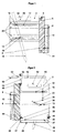
- Anchoring part is a plate 2, for example made of iron provided, which in use is approximately perpendicular to the floor the construction pit is standing.
- Edge part 4 angled and forms a contact surface for a external square wood 6, which is fastened with screws 8 is in through appropriate nail holes in the edge part the squared timber will be felled.
- formwork boards or formwork panels 10 can then be nailed on, as indicated in Fig. 1.
- Two horizontal slots 12 are formed in the plate 2, in each of which an eyelet holder 14 is slidable.
- the eyelet holders wear on one side an eyelet 16 for receiving a dashed drawn anchoring pole 18, by both Eyes 16 is inserted and in the range of motion Eyelet holder 14 can pivot in the slots 12 so that it be driven into the most suitable location on the building site can until he's stuck.
- the Plate 2 is then aligned with the stuck pile that the square wood 6 in the desired position for nailing the formwork board 10 is brought. Move it the eyelet holder 14 with the eyelets 16 in the slots 12, and this possibility of movement allows shifting, tipping and rotating the plate 2 relative to the one sitting firmly in the ground Anchoring pile 18, resulting in an adjustment range which allows to compensate for all uneven floors.
- the plate 2 is fixed to the anchoring post 18 by tightening the eyelets 16 with the aid of a clamping element, which is shown in Fig. 4 in the form of a wedge 20, but can also be formed by a screw connection, as in Fig. 2 is drawn below and in Fig. 3 on the right.
- a clamping element which is shown in Fig. 4 in the form of a wedge 20, but can also be formed by a screw connection, as in Fig. 2 is drawn below and in Fig. 3 on the right.
- the Wedge connection protrudes a plate-shaped extension 22 of the eyelet 16 through the slot 12 and in turn has a wedge slot 24 to hold the wedge 20, which can then be used with a hammer can be knocked down and the pile 18 with the help of the eyelet 16 presses against two abutments 26, which are in the form of parallel to the slots 12 provided elevations on the plate 2 are.
- the wedge is conveniently with a side Approach 30 provided, with the help of which he is out again the wedge slot 24 can knock out.
- the wedge 20 At the bottom is the wedge 20 on its side facing the plate 2 one, e.g. elliptical rounding 29 formed so that it - As Fig. 4 shows - fall to the side in the released state can.
- the wedge is at the bottom to prevent it from falling out by a split pin 28 and above by a side weld nipple or secured another split pin 31.
- the split pin 28 after inserting the wedge 20 through the wedge slot 24 struck in a bore provided at the lower wedge end, and thus the wedge and eyelet holder are captive plate 2, e.g.
- the eyelet 16 thicker than that Width of the slot 12 can be made so that it is not slips through. If you form eyelet holders and eyelets e.g. from one Steel plate, so you can slip through by attaching a thickening, like one bent out of the plane of the plate Piece of material or a weld nipple. Instead of the wedge fixation, you can also use a screw fixation provide.
- the eyelet then projects through with a thread 32 the slot, and with a screwed fixing nut 34 can the pile 18 clamped by the eyelet 16 against the abutment 26 become.
- the fixing nut is for easier handling 24 expediently provided with a handle extension 36, for example in the form of a piece of rod on the side of the mother can be welded.
- FIGS. 2 and 3 It can also be seen in FIGS. 2 and 3 at the bottom of the Plate protruding tabs 38 with nail holes 40 with which the slab on a slab formwork protruding beyond the wall edge can be nailed if not for the forehead formwork a floor slab, but a floor ceiling shall be.
- the tabs 38 each have a larger center hole 42, so that the bracket also in the usual way with double-headed floor posts can be attached to the ground.
- a further tab also protrudes below from the stop part 2 in shape a stop tab 44 away, which is a support for a formwork board or forms a formwork panel 10.
- a vertical guide tube can also be seen in FIGS. 2 and 4 48, for example welded to the side of the plate is and slidably receives a rod 50, which in turn at the upper end carries a horizontal sleeve 52, in which is displaceable at one end of a rod-shaped rod 54 is stored.
- Fixing screws 56 can be used fix the rods 50 and 54 in the desired position.
- reinforcing bars can for the reinforcement of the floor slab or floor slab to be concreted be hooked in, the edge formwork described Bracket serves. You can also use a vertical guide tube for inserting a railing bracket on the plate provide.
Landscapes
- Engineering & Computer Science (AREA)
- Architecture (AREA)
- Mechanical Engineering (AREA)
- Civil Engineering (AREA)
- Structural Engineering (AREA)
- Forms Removed On Construction Sites Or Auxiliary Members Thereof (AREA)
Applications Claiming Priority (2)
| Application Number | Priority Date | Filing Date | Title |
|---|---|---|---|
| DE19939845 | 1999-08-23 | ||
| DE1999139845 DE19939845A1 (de) | 1999-08-23 | 1999-08-23 | Halterung für Bodenplatten-Randabschalungen |
Publications (3)
| Publication Number | Publication Date |
|---|---|
| EP1079042A2 true EP1079042A2 (fr) | 2001-02-28 |
| EP1079042A3 EP1079042A3 (fr) | 2003-05-14 |
| EP1079042B1 EP1079042B1 (fr) | 2007-09-19 |
Family
ID=7919271
Family Applications (1)
| Application Number | Title | Priority Date | Filing Date |
|---|---|---|---|
| EP20000117846 Expired - Lifetime EP1079042B1 (fr) | 1999-08-23 | 2000-08-18 | Support de coffrage de bordure de dalle |
Country Status (2)
| Country | Link |
|---|---|
| EP (1) | EP1079042B1 (fr) |
| DE (2) | DE19939845A1 (fr) |
Family Cites Families (6)
| Publication number | Priority date | Publication date | Assignee | Title |
|---|---|---|---|---|
| DE1684236A1 (de) * | 1966-12-31 | 1971-04-01 | Hans Fiedler | Stuetzvorrichtung fuer die Verschalung von Unterzuegen und Fensterstuerzen |
| US4104356A (en) * | 1977-01-26 | 1978-08-01 | Joseph Paul Deutsch | Tilt-up panel bracket |
| CH666075A5 (de) * | 1984-05-29 | 1988-06-30 | Hanspeter Walser | Vorrichtung zum loesbaren festhalten von schaltafeln, nach gebrauch im beton zu verbleiben bestimmter bodensteckteil sowie verwendung der vorrichtung. |
| CH675143A5 (en) * | 1988-03-09 | 1990-08-31 | A & B Amberg Geb | Support for shuttering panels for concrete floors - comprises bar and slotted metal plate to enable shuttering to be adjusted horizontally and vertically |
| US5228262A (en) * | 1991-10-18 | 1993-07-20 | Meriwether Irvin F | Anchor assembly |
| WO1996005388A1 (fr) * | 1994-08-16 | 1996-02-22 | David James Pratt | Ensemble formant caisson ajustable |
-
1999
- 1999-08-23 DE DE1999139845 patent/DE19939845A1/de not_active Withdrawn
-
2000
- 2000-08-18 DE DE50014663T patent/DE50014663D1/de not_active Expired - Lifetime
- 2000-08-18 EP EP20000117846 patent/EP1079042B1/fr not_active Expired - Lifetime
Also Published As
| Publication number | Publication date |
|---|---|
| DE50014663D1 (de) | 2007-10-31 |
| EP1079042B1 (fr) | 2007-09-19 |
| EP1079042A3 (fr) | 2003-05-14 |
| DE19939845A1 (de) | 2001-03-01 |
Similar Documents
| Publication | Publication Date | Title |
|---|---|---|
| DE3004245C2 (de) | Deckenschalung mit Fallköpfen | |
| EP1538278A2 (fr) | Table de coffrage | |
| EP3358107A1 (fr) | Collier de serrage pour coffrage | |
| EP0028662A2 (fr) | Support pour signaux à manchons de maintien d'un panneau | |
| EP1304429B1 (fr) | Coffrage pour béton avec étaiement latéral | |
| DE3140142A1 (de) | Systemschalung fuer betondecke mit unterzug | |
| EP2273038A2 (fr) | Coffrage et procédé de montage d'un coffrage | |
| DE60114252T2 (de) | Befestigungskonstruktion und Installationsverfahren | |
| EP0049880A1 (fr) | Système de coffrage pour la coulée de planchers nervurés en béton | |
| DE19533421C1 (de) | Haltevorrichtung zum Halten eines Schalelements | |
| DE10120897A1 (de) | Seitenschutzpfosten zum Erstellen von Absturzsicherungen an Bauwerken | |
| EP1079042B1 (fr) | Support de coffrage de bordure de dalle | |
| DE19726102A1 (de) | Haltekopf für Stahlstützenbau | |
| DE102007000866A1 (de) | Universalkonsole | |
| DE3730846A1 (de) | Vorrichtung zum errichten einer begehbaren arbeitsbuehne | |
| EP0603449A1 (fr) | Ensemble de façade | |
| EP0593017B1 (fr) | Pièce de raccordement | |
| DE2807043A1 (de) | Tragvorrichtung fuer ein schnurgeruest o.dgl. | |
| DE4234701C2 (de) | Verbindungsteil | |
| AT400465B (de) | Schalung und verfahren zum giessen eines behälters aus beton | |
| DE3503186C2 (fr) | ||
| EP1079037A2 (fr) | Procédé de réalisation d'un coffrage de bordure de dalle et coffrage relatif | |
| DE19506931C2 (de) | Im Erdboden verankerbare Haltevorrichtung | |
| CH685830A5 (de) | Deckenabschalungskonstruktion. | |
| DE3107844A1 (de) | Schalungselement aus stahl fuer die herstellung von bauwerken aus beton |
Legal Events
| Date | Code | Title | Description |
|---|---|---|---|
| PUAI | Public reference made under article 153(3) epc to a published international application that has entered the european phase |
Free format text: ORIGINAL CODE: 0009012 |
|
| AK | Designated contracting states |
Kind code of ref document: A2 Designated state(s): AT BE CH CY DE DK ES FI FR GB GR IE IT LI LU MC NL PT SE |
|
| AX | Request for extension of the european patent |
Free format text: AL;LT;LV;MK;RO;SI |
|
| PUAL | Search report despatched |
Free format text: ORIGINAL CODE: 0009013 |
|
| AK | Designated contracting states |
Designated state(s): AT BE CH CY DE DK ES FI FR GB GR IE IT LI LU MC NL PT SE |
|
| AX | Request for extension of the european patent |
Extension state: AL LT LV MK RO SI |
|
| RIC1 | Information provided on ipc code assigned before grant |
Ipc: 7E 04G 11/36 B Ipc: 7E 04G 13/00 A Ipc: 7E 04G 17/00 B Ipc: 7E 04G 17/14 B |
|
| 17P | Request for examination filed |
Effective date: 20031015 |
|
| AKX | Designation fees paid |
Designated state(s): CH DE LI |
|
| GRAP | Despatch of communication of intention to grant a patent |
Free format text: ORIGINAL CODE: EPIDOSNIGR1 |
|
| GRAS | Grant fee paid |
Free format text: ORIGINAL CODE: EPIDOSNIGR3 |
|
| GRAA | (expected) grant |
Free format text: ORIGINAL CODE: 0009210 |
|
| AK | Designated contracting states |
Kind code of ref document: B1 Designated state(s): CH DE LI |
|
| REG | Reference to a national code |
Ref country code: CH Ref legal event code: EP Ref country code: CH Ref legal event code: NV Representative=s name: HANS RUDOLF GACHNANG PATENTANWALT |
|
| REF | Corresponds to: |
Ref document number: 50014663 Country of ref document: DE Date of ref document: 20071031 Kind code of ref document: P |
|
| PLBE | No opposition filed within time limit |
Free format text: ORIGINAL CODE: 0009261 |
|
| STAA | Information on the status of an ep patent application or granted ep patent |
Free format text: STATUS: NO OPPOSITION FILED WITHIN TIME LIMIT |
|
| 26N | No opposition filed |
Effective date: 20080620 |
|
| REG | Reference to a national code |
Ref country code: CH Ref legal event code: NV Representative=s name: GACHNANG AG PATENTANWAELTE, CH |
|
| PGFP | Annual fee paid to national office [announced via postgrant information from national office to epo] |
Ref country code: DE Payment date: 20190822 Year of fee payment: 20 |
|
| PGFP | Annual fee paid to national office [announced via postgrant information from national office to epo] |
Ref country code: CH Payment date: 20190830 Year of fee payment: 20 |
|
| REG | Reference to a national code |
Ref country code: DE Ref legal event code: R071 Ref document number: 50014663 Country of ref document: DE |
|
| REG | Reference to a national code |
Ref country code: CH Ref legal event code: PL |