EP1087125A2 - Vergaser mit Drehschieber und verbessertem Brennstoffkanalsystem - Google Patents
Vergaser mit Drehschieber und verbessertem Brennstoffkanalsystem Download PDFInfo
- Publication number
- EP1087125A2 EP1087125A2 EP00118086A EP00118086A EP1087125A2 EP 1087125 A2 EP1087125 A2 EP 1087125A2 EP 00118086 A EP00118086 A EP 00118086A EP 00118086 A EP00118086 A EP 00118086A EP 1087125 A2 EP1087125 A2 EP 1087125A2
- Authority
- EP
- European Patent Office
- Prior art keywords
- fuel
- chamber
- passage
- valve
- carburetor
- Prior art date
- Legal status (The legal status is an assumption and is not a legal conclusion. Google has not performed a legal analysis and makes no representation as to the accuracy of the status listed.)
- Withdrawn
Links
Images

Classifications
-
- F—MECHANICAL ENGINEERING; LIGHTING; HEATING; WEAPONS; BLASTING
- F02—COMBUSTION ENGINES; HOT-GAS OR COMBUSTION-PRODUCT ENGINE PLANTS
- F02M—SUPPLYING COMBUSTION ENGINES IN GENERAL WITH COMBUSTIBLE MIXTURES OR CONSTITUENTS THEREOF
- F02M17/00—Carburettors having pertinent characteristics not provided for in, or of interest apart from, the apparatus of preceding main groups F02M1/00 - F02M15/00
- F02M17/02—Floatless carburettors
- F02M17/04—Floatless carburettors having fuel inlet valve controlled by diaphragm
-
- F—MECHANICAL ENGINEERING; LIGHTING; HEATING; WEAPONS; BLASTING
- F02—COMBUSTION ENGINES; HOT-GAS OR COMBUSTION-PRODUCT ENGINE PLANTS
- F02M—SUPPLYING COMBUSTION ENGINES IN GENERAL WITH COMBUSTIBLE MIXTURES OR CONSTITUENTS THEREOF
- F02M9/00—Carburettors having air or fuel-air mixture passage throttling valves other than of butterfly type; Carburettors having fuel-air mixing chambers of variable shape or position
- F02M9/08—Carburettors having air or fuel-air mixture passage throttling valves other than of butterfly type; Carburettors having fuel-air mixing chambers of variable shape or position having throttling valves rotatably mounted in the passage
- F02M9/085—Fuel spray nozzles in the throttling valves
-
- Y—GENERAL TAGGING OF NEW TECHNOLOGICAL DEVELOPMENTS; GENERAL TAGGING OF CROSS-SECTIONAL TECHNOLOGIES SPANNING OVER SEVERAL SECTIONS OF THE IPC; TECHNICAL SUBJECTS COVERED BY FORMER USPC CROSS-REFERENCE ART COLLECTIONS [XRACs] AND DIGESTS
- Y10—TECHNICAL SUBJECTS COVERED BY FORMER USPC
- Y10S—TECHNICAL SUBJECTS COVERED BY FORMER USPC CROSS-REFERENCE ART COLLECTIONS [XRACs] AND DIGESTS
- Y10S261/00—Gas and liquid contact apparatus
- Y10S261/39—Liquid feeding nozzles
Definitions
- the present invention relates to a rotary throttle valve type carburetor and accelerator system for an internal combustion engine mounted on a carrying work machine, such as a temporary sweeper, and more specifically, to a rotary throttle valve type carburetor having a fuel delivery circuit that controls the amount of fuel delivered to an engine during acceleration and/or high-speed operation of the engine.
- a check valve 53 and a fuel jet 7 are disposed along and mounted in a fuel passage 8a that connects a fuel supply nozzle 5 with a constant pressure fuel chamber 13.
- the fuel supply nozzle 5 is fixed at the bottom of a valve chamber 2 which is defined in a carburetor body 30.
- a rotary throttle valve 3 is movably fitted within the valve chamber 2 of the carburetor body 30.
- An intermediate wall 38 is connected to the bottom of the carburetor body 30, and a constant pressure fuel chamber 13 is disposed under the intermediate wall 38.
- the length of the fuel passage 8a that connects the constant pressure fuel chamber 13 with the fuel supply nozzle 5 is short.
- the amount of fuel fed and delivered into the valve chamber 2 via the fuel passage 8a and the fuel supply nozzle 5 increases, in an undesirable geometric series manner, and becomes excessive as the number of revolutions per minute or speed of the engine increases.
- Such an excessive increase in the amount of fuel is represented by a solid curve 55 illustrated in FIG. 2.
- the amount of fuel fed from the constant pressure fuel chamber 13 is indeed adjusted by the fuel jet 7, the fed amount of fuel is still undesirably excessive upon full admission or opening of the rotary throttle valve 3.
- a more desired and/or required characteristic of the relationship is that both (1) a necessary and proper amount of fuel be secured upon idling, and (2) the amount of fed fuel increases nearly linearly (such as in an arithmetic series) in proportion to the number of revolutions per minute of the engine, as represented by a dashed curve 54 illustrated in FIG. 2.
- the present invention provides a circuit for delivering fuel into a valve chamber defined in a carburetor body of a rotary throttle valve type carburetor for an engine.
- the fuel delivery circuit basically includes a fuel supply nozzle, protruding into the valve chamber and fixed at the bottom of the valve chamber to the carburetor body, and an intermediate wall.
- the intermediate wall is connected to the bottom of the carburetor body.
- the intermediate wall has a first chamber defined therein, a second chamber defined therein, and structure which cooperatively defines a first passage and a second passage therein.
- the first passage communicates the first chamber to the fixed end of the fuel supply nozzle, and the second passage communicates the second chamber to the first chamber.
- the fuel delivery circuit also basically includes an enclosure having a pressurized fuel chamber disposed under the intermediate wall, wherein the intermediate wall structure cooperatively defines a third passage that communicates the pressurized fuel chamber to the second chamber.
- the fuel delivery circuit also basically includes a fuel jet, disposed along the first passage, and a check valve, disposed along the first passage between the fuel jet and the first chamber. In this way, the first passage, the first chamber, the second passage, the second chamber, and the third passage cooperatively define an elongated fuel passage between the pressurized fuel chamber and the fuel supply nozzle for delivering fuel into the valve chamber.
- the elongated fuel passage defined in the fuel delivery circuit generally serves to increase the fluid resistance of the fuel delivery circuit as compared to other conventional fuel delivery circuits.
- the fluid resistance through the fuel delivery circuit is therefore low as well.
- the increased fluid resistance attributable to the elongated fuel passage of the fuel delivery circuit is practically negligible during low-speed operation of the engine.
- the amount of fuel delivered to the engine is sufficiently restricted by the elongated fuel passage such that the amount of fuel delivered to the engine increases in nearly linear proportion to the number of revolutions per minute of the engine.
- the delivery of an excessive amount of fuel to the engine during acceleration and/or high-speed operation of the engine is successfully avoided.
- a fuel supply characteristic which is better matched to the amount of fuel that the engine actually requires is successfully obtained.
- the fuel delivery circuit also includes a fuel pump and an inlet valve.
- the inlet valve is preferably situated between the fuel pump and the pressurized fuel chamber such that the inlet valve is able to provide fluid communication between the fuel pump and the pressurized fuel chamber.
- the inlet valve is also preferably situated proximate to the opening defined by the third passage in the enclosure of the pressurized fuel chamber.
- the pressurized fuel chamber preferably has a substantially constant pressure and maintains a substantially constant level of fuel. In this way, a continuous supply of fuel, including fresh fuel unaffected by surrounding heat, is introduced into the third passage. As a result, smooth operation of the engine is ensured.
- the first chamber of the fuel delivery circuit is preferably situated under the fixed end of the fuel supply nozzle such that the first chamber structurally accommodates the check valve.
- the first chamber is also preferably situated such that the floor of the second chamber is higher than the floor of the first chamber.
- the elongated fuel passage is preferably both substantially non-vertical and substantially non-linear.
- the elongated fuel passage, from the pressurized fuel chamber up to the fuel jet preferably has a diameter which is larger than the inner diameter of the fuel jet.
- a fuel delivery circuit as described above is specifically incorporated in a rotary throttle valve type carburetor and accelerator system.
- a rotary throttle valve type carburetor and accelerator system includes a carburetor body, having a cylindrical valve chamber defined therein which crosses an intake passage defined therethrough, and a cylindrical rotary throttle valve, having a throttle bore.
- the cylindrical rotary throttle valve is fitted in the cylindrical valve chamber such that the throttle valve moves rotatively and slidably within the carburetor body.
- the system also includes a fuel supply nozzle, fixed at the bottom of the cylindrical valve chamber and protruding into the valve chamber to the throttle bore of the throttle valve, and a needle, supported by the throttle valve for insertion into the fuel supply nozzle.
- the system also includes an intermediate wall, connected to the bottom of the carburetor body, having a first chamber and a second chamber separately defined therein.
- An enclosure having a pressurized fuel chamber, is disposed under the intermediate wall.
- a check valve and a fuel jet also included within the system, are disposed in a first passage that communicates the first chamber to the fuel supply nozzle.
- a second passage included within the system communicates the second chamber to the first chamber, and a third passage within the system communicates the pressurized fuel chamber to the second chamber.
- the first passage, the first chamber, the second passage, the second chamber, and the third passage within the system all cooperatively define an elongated fuel passage between the pressurized fuel chamber and the fuel supply nozzle for delivering fuel into the valve chamber.
- Objects, features, and advantages of the present invention include providing a fuel delivery circuit having an elongated fuel passage, wherein the elongated fuel passage sufficiently restricts the amount of fuel delivered to an engine during acceleration and/or high-speed operation, and also providing a fuel delivery circuit which is compact, rugged, durable, of relatively simple design, of economical manufacture and assembly, and which has a long, useful life in service.
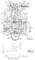
- FIG. 1 illustrates a rotary throttle valve type carburetor embodying the present invention with a carburetor body 30 having a cylindrical valve chamber 2 in which a rotary throttle valve 3 is slidably received to be rotated and moved up and down.
- the cylindrical valve chamber 2 perpendicularly crosses an intake passage 4A (a passage extending perpendicular to the plane of FIG. 1) that penetrates the carburetor body 30.
- An air cleaner (not shown) is connectable to an end of the carburetor body 30, and the other end of the carburetor body 30 is connectable to the air inlet of an engine (not shown) through a heat insulation pipe (not shown) by bolts insertable into a pair of left and right holes 32 defined in end flanges 31.
- air in the intake passage 4A is mixed with fuel fed from a fuel supply nozzle 5 in a throttle bore 4 and then supplied to a crank chamber (not shown) of a two-stroke engine through the heat insulation pipe.
- the upper end of the shaft 3a is connected to a throttle valve lever 22.
- a spring 25, surrounding the shaft 3a, is attached between the cap 23 and the rotary throttle valve 3.
- One end of the spring 25 is fixed to the rotary throttle valve 3, and the other end of the spring 25 is fixed to the cap 23. Due to the force of the spring 25, the rotary throttle valve 3 is rotatively energized to be in its idle position (that is, a position to close or throttle the intake passage 4A).
- a dust-proof boot 24 is attached between the cap 23 and the throttle valve lever 22.
- a cam face formed on a lower surface of the throttle valve lever 22, is biased against a cam follower (not shown) which protrudes upward from the cap 23 by the force of the spring 25.
- a cam follower (not shown) which protrudes upward from the cap 23 by the force of the spring 25.
- the cap 23 is fixed to the carburetor body 30 by a plurality of bolts (not shown).
- An idling-adjusting screw 23b that abuts the throttle valve lever 22 for adjusting the idling position, is fixed in a wall 23a that protrudes upward from the cap 23.
- An outer tube of a remote control cable (not shown) is fixable to the wall 23a, and an inner wire inserted into the outer tube is connectable to the throttle valve lever 22 through a swivel 21. In this way, an operator who operates a work machine-mounted engine having the carburetor of FIG. 1 can thereby operate the throttle valve lever 22 by remote control.
- the fuel supply nozzle 5 is fixed at the bottom of the valve chamber 2 of the carburetor body 30 and communicates with an enclosed, pressurized fuel chamber 13 (that is, a metering chamber), having a substantially constant pressure, which is associated with a constant pressure fuel supply mechanism as explained hereinbelow.
- a diaphragm 36 of a fuel pump 34 is arranged between the carburetor body 30 and an intermediate wall 38.
- a chamber 35, for introducing fluid under a pulsating pressure, and a pump chamber 37 are partitively disposed over and under the diaphragm 36, respectively.
- the diaphragm 36 functions as an admission and delivery valve, moving up and down in accordance with the pulsating pressure of a crank chamber of the engine, sucking in fuel from a fuel tank (not shown) through a fuel pipe 52 to the pump chamber 37 of the fuel pump 34, and supplying the fuel to the constant pressure fuel chamber 13 through a chamber 39 and an inlet valve 40.
- a diaphragm 42 is arranged between the intermediate wall 38 and another intermediate wall 43.
- the constant pressure fuel chamber 13 and an air chamber 50 are partitively disposed over and under the diaphragm 42, respectively.
- a manually actuated primer or suction pump 46 has a flexible bulb 49 attached to the back of the intermediate wall 43 by bolts (not shown) through a retaining plate 45.
- a pump chamber 48 in which a mushroom-shaped composite valve 47 functioning as admission and delivery valves is attached.
- the bulb 49 is repetitively manually pressed and released to suck the fuel vapor and air into the pump chamber 48 around a flexible lip portion of the composite valve 47. Then, the fuel vapor and air are transferred back to the fuel tank through a central shank and duckbill valve part of the composite valve 47, a passage 51, and an exhaust pipe 41.
- the constant pressure fuel chamber 13 is under a negative pressure, the fuel in the fuel tank is supplied to the constant pressure fuel chamber 13 through the pump chamber 37, the chamber 39, and the inlet valve 40.
- the constant pressure fuel chamber 13 is partitively disposed by the diaphragm 42 under the intermediate wall 38 that is connected to the bottom of the carburetor 30.
- a first chamber 8 and a second chamber 6 are provided and disposed in the intermediate wall 38.
- the first chamber 8 is situated under the fuel supply nozzle 5 and thereby communicates with the bottom of the fuel supply nozzle 5 and also structurally accommodates a check valve 53.
- the overall length of the fuel passage defined from the constant pressure fuel chamber 13 to the fuel supply nozzle 5, through the check valve 53 and a fuel jet 7, is elongated as compared to the fuel passage 8a in the conventional rotary throttle valve type carburetor of FIG. 3.
- the fluid resistance in the fuel passage is therefore also relatively low.
- the throttle lever 22 is rotated in an accelerating direction, the open area ratio of the throttle bore 4 with respect to the intake passage 4A is increased, and at the same time, the needle 33 rises due to the cam mechanism. As a result, the open area ratio of the fuel injection hole of the fuel supply nozzle 5 increases.
- the fuel in the constant pressure fuel chamber 13 is then transferred to the throttle bore 4 through the third passage 10, the second chamber 6, the second passage 9, the first chamber 8, the check valve 53, the fuel jet 7, the fuel supply nozzle 5, and the fuel injection hole of the fuel supply nozzle 5. Consequently, smooth acceleration of the engine is obtained by the increase in the amount of fuel and air.
- the engine reaches and operates at a high speed, since the amount of fuel to be consumed is increased and the flow speed of the fuel flowing in the fuel passage from the third passage 10 up to the fuel supply nozzle 5 becomes high, the fluid resistance in the fuel passage becomes higher as compared to the fluid resistance during low-speed operation.
- the rate of increase in the amount of fuel (that is, the gradient of the fuel supply characteristic curve illustrated in Figure 2) upon high-speed operation is restricted by the making of the length of the above-mentioned fuel passage longer. That is, as demonstrated by a dashed curve 54 illustrated in Figure 2, the amount of fuel under all conditions, ranging from the state of the rotary throttle valve 3 being essentially closed or throttled (during idle operation) to the state of the rotary throttle valve 3 being fully opened, is increased nearly linearly as a whole. As a result, the problem of feeding and delivering an excess amount of fuel when the rotary throttle valve 3 is fully opened is thereby eliminated. Thus, a fuel supply characteristic which is better suited to the amount of fuel that the engine actually requires is obtained, and the acceleration characteristics of the engine are also improved.
- the inner diameter of the fuel passage from the constant pressure fuel chamber 13 up to the fuel jet 7 is preferably larger than the inner diameter of the fuel jet 7 and is set up to be 1 millimeter or less with respect to a two-cycle engine of about 30 cc displacement.
- the length of the fuel passage is made longer from the constant pressure fuel chamber 13 up to the fuel supply nozzle 5 through the check valve 53 and the fuel jet 7, the required amount of fuel is still successfully secured upon low-speed operation of the engine due to the naturally low fluid resistance resulting from the characteristic low fuel flow rate during low-speed operation.
- the amount of fuel delivered to the engine is sufficiently restricted by the increased fluid resistance created by the elongated fuel passage such that the amount of fuel delivered to the engine increases in a nearly linear proportion to the number of revolutions per minute of the engine. In this way, the delivery of an excessive amount of fuel to the engine during acceleration and/or high-speed operation of the engine is successfully avoided.
Landscapes
- Engineering & Computer Science (AREA)
- Chemical & Material Sciences (AREA)
- Combustion & Propulsion (AREA)
- Mechanical Engineering (AREA)
- General Engineering & Computer Science (AREA)
- Control Of The Air-Fuel Ratio Of Carburetors (AREA)
Applications Claiming Priority (2)
| Application Number | Priority Date | Filing Date | Title |
|---|---|---|---|
| JP27074799 | 1999-09-24 | ||
| JP27074799A JP2001090612A (ja) | 1999-09-24 | 1999-09-24 | ロータリ絞り弁式気化器 |
Publications (2)
| Publication Number | Publication Date |
|---|---|
| EP1087125A2 true EP1087125A2 (de) | 2001-03-28 |
| EP1087125A3 EP1087125A3 (de) | 2001-12-05 |
Family
ID=17490424
Family Applications (1)
| Application Number | Title | Priority Date | Filing Date |
|---|---|---|---|
| EP00118086A Withdrawn EP1087125A3 (de) | 1999-09-24 | 2000-08-23 | Vergaser mit Drehschieber und verbessertem Brennstoffkanalsystem |
Country Status (3)
| Country | Link |
|---|---|
| US (1) | US6382599B1 (de) |
| EP (1) | EP1087125A3 (de) |
| JP (1) | JP2001090612A (de) |
Cited By (1)
| Publication number | Priority date | Publication date | Assignee | Title |
|---|---|---|---|---|
| CN105604744A (zh) * | 2015-09-06 | 2016-05-25 | 中国南方航空工业(集团)有限公司 | 气动加速装置及具有该加速装置的发动机燃气汽化系统 |
Families Citing this family (6)
| Publication number | Priority date | Publication date | Assignee | Title |
|---|---|---|---|---|
| US6715737B2 (en) | 2000-08-29 | 2004-04-06 | Walbro Corporation | Fuel metering system for a carburetor |
| DE10048502C1 (de) * | 2000-09-29 | 2002-04-04 | Raymond A & Cie | Steckverbindung mit Auslaufsperre |
| US7287741B2 (en) * | 2004-02-09 | 2007-10-30 | Walbro Japan, Inc. | Rotary throttle valve carburetor |
| US7172178B1 (en) | 2004-11-24 | 2007-02-06 | Walbro Engine Management, L.L.C. | Carburetor with acceleration fuel pump |
| JP5908667B2 (ja) * | 2010-02-25 | 2016-04-26 | ザマ・ジャパン株式会社 | 回転絞り弁式気化器における弁軸の防塵シール構造 |
| CN113074066B (zh) * | 2021-05-12 | 2024-09-24 | 福建省大立通用机电制造有限公司 | 一种耐高温自循环装置 |
Family Cites Families (12)
| Publication number | Priority date | Publication date | Assignee | Title |
|---|---|---|---|---|
| US3843755A (en) * | 1973-03-29 | 1974-10-22 | Walbro Corp | Carburetor with check valve bypass |
| JPS6029828B2 (ja) * | 1978-11-20 | 1985-07-12 | 株式会社ウオルブロ−・フア−イ−スト | ロ−タリスロットル弁式気化器 |
| JPS5752347Y2 (de) * | 1979-06-18 | 1982-11-13 | ||
| JPS58101253A (ja) * | 1981-12-10 | 1983-06-16 | Walbro Far East | ロ−タリスロツトル弁式気化器 |
| JPH0237158A (ja) | 1988-07-27 | 1990-02-07 | Walbro Far East Inc | ダイヤフラム型気化器 |
| JPH04339161A (ja) * | 1991-01-23 | 1992-11-26 | Walbro Far East Inc | ダイヤフラム型気化器の燃料調整機構 |
| JPH08105357A (ja) * | 1994-10-06 | 1996-04-23 | Nippon Walbro:Kk | ロータリ絞り弁式気化器における燃料供給管の構造 |
| JP2968707B2 (ja) * | 1995-07-10 | 1999-11-02 | 株式会社日本ウォルブロー | ロータリ絞り弁式気化器の燃料調整機構 |
| US5711901A (en) * | 1996-06-05 | 1998-01-27 | Walbro Corporation | Carburetor having temperature-compensated purge/primer |
| JPH11125146A (ja) | 1997-10-22 | 1999-05-11 | Zama Japan Kk | 回転絞り弁式気化器の加速装置 |
| JP3730785B2 (ja) * | 1998-07-28 | 2006-01-05 | 本田技研工業株式会社 | フロートレス型気化器 |
| JP2000045876A (ja) * | 1998-07-28 | 2000-02-15 | Honda Motor Co Ltd | フロートレス型気化器 |
-
1999
- 1999-09-24 JP JP27074799A patent/JP2001090612A/ja active Pending
-
2000
- 2000-08-01 US US09/630,080 patent/US6382599B1/en not_active Expired - Fee Related
- 2000-08-23 EP EP00118086A patent/EP1087125A3/de not_active Withdrawn
Cited By (1)
| Publication number | Priority date | Publication date | Assignee | Title |
|---|---|---|---|---|
| CN105604744A (zh) * | 2015-09-06 | 2016-05-25 | 中国南方航空工业(集团)有限公司 | 气动加速装置及具有该加速装置的发动机燃气汽化系统 |
Also Published As
| Publication number | Publication date |
|---|---|
| JP2001090612A (ja) | 2001-04-03 |
| EP1087125A3 (de) | 2001-12-05 |
| US6382599B1 (en) | 2002-05-07 |
Similar Documents
| Publication | Publication Date | Title |
|---|---|---|
| CN109072818B (zh) | 用于燃烧发动机的低压燃料和空气充气形成设备 | |
| US5709822A (en) | Fuel regulating mechanism for a rotary throttle valve type carburetor | |
| US6769670B2 (en) | Starting assembly for a carburetor | |
| US6293524B1 (en) | Carburetor with accelerating device | |
| US6019075A (en) | Air and fuel delivery system for fuel injected engines | |
| EP0598990B1 (de) | Vergaser mit Beschleuniger und Leerlaufkreislaufabsperrung | |
| US6481699B1 (en) | Acceleration device for a two-cycle engine | |
| US4369749A (en) | Variable venturi carburetor | |
| US6382599B1 (en) | Carburetor with accelerator | |
| US6913250B2 (en) | Carburetor arrangement | |
| ITRM940666A1 (it) | Sistema per il controllo delle emissioni per piccoli motori | |
| US6928996B2 (en) | Stratified scavenging mechanism of a two-stroke engine | |
| US7717403B2 (en) | Accelerator device for a carburetor | |
| US6557833B1 (en) | Priming system for an engine carburetor | |
| GB2082258A (en) | Fuel metering in suction piston carburetors | |
| US12429019B2 (en) | Fuel and air charge forming device | |
| US6217008B1 (en) | Diaphragm-type carburetor | |
| US6874482B2 (en) | Diaphragm carburetor with air purge system | |
| AU2001296759A1 (en) | Priming system for an engine carburetor | |
| EP1342906B1 (de) | Vergaser mit Leerkraftstoffversorgungsanlage | |
| US4539163A (en) | Carburetor | |
| US3236217A (en) | Fuel feed system for internal combustion engines | |
| JP2000265906A (ja) | 気化器の加速装置 | |
| JPH10238411A (ja) | 加速装置付き気化器 | |
| JPS61229965A (ja) | 可変ベンチユリ気化器 |
Legal Events
| Date | Code | Title | Description |
|---|---|---|---|
| PUAI | Public reference made under article 153(3) epc to a published international application that has entered the european phase |
Free format text: ORIGINAL CODE: 0009012 |
|
| AK | Designated contracting states |
Kind code of ref document: A2 Designated state(s): AT BE CH CY DE DK ES FI FR GB GR IE IT LI LU MC NL PT SE Kind code of ref document: A2 Designated state(s): DE IT SE |
|
| AX | Request for extension of the european patent |
Free format text: AL;LT;LV;MK;RO;SI |
|
| PUAL | Search report despatched |
Free format text: ORIGINAL CODE: 0009013 |
|
| AK | Designated contracting states |
Kind code of ref document: A3 Designated state(s): AT BE CH CY DE DK ES FI FR GB GR IE IT LI LU MC NL PT SE |
|
| AX | Request for extension of the european patent |
Free format text: AL;LT;LV;MK;RO;SI |
|
| 17P | Request for examination filed |
Effective date: 20020605 |
|
| AKX | Designation fees paid |
Free format text: DE IT SE |
|
| GRAP | Despatch of communication of intention to grant a patent |
Free format text: ORIGINAL CODE: EPIDOSNIGR1 |
|
| GRAS | Grant fee paid |
Free format text: ORIGINAL CODE: EPIDOSNIGR3 |
|
| STAA | Information on the status of an ep patent application or granted ep patent |
Free format text: STATUS: THE APPLICATION IS DEEMED TO BE WITHDRAWN |
|
| 18D | Application deemed to be withdrawn |
Effective date: 20050203 |