EP1087502A2 - Dauermagnet-Schrittmotor - Google Patents
Dauermagnet-Schrittmotor Download PDFInfo
- Publication number
- EP1087502A2 EP1087502A2 EP00120745A EP00120745A EP1087502A2 EP 1087502 A2 EP1087502 A2 EP 1087502A2 EP 00120745 A EP00120745 A EP 00120745A EP 00120745 A EP00120745 A EP 00120745A EP 1087502 A2 EP1087502 A2 EP 1087502A2
- Authority
- EP
- European Patent Office
- Prior art keywords
- stator
- teeth
- stator teeth
- rotor
- yoke
- Prior art date
- Legal status (The legal status is an assumption and is not a legal conclusion. Google has not performed a legal analysis and makes no representation as to the accuracy of the status listed.)
- Granted
Links
- 238000010276 construction Methods 0.000 claims description 23
- 230000002093 peripheral effect Effects 0.000 claims description 12
- 230000005489 elastic deformation Effects 0.000 claims description 6
- 125000006850 spacer group Chemical group 0.000 claims description 6
- 239000000696 magnetic material Substances 0.000 claims description 5
- 238000000465 moulding Methods 0.000 claims description 3
- 239000011295 pitch Substances 0.000 description 62
- 230000009467 reduction Effects 0.000 description 11
- 238000010586 diagram Methods 0.000 description 8
- 238000003466 welding Methods 0.000 description 6
- 238000011161 development Methods 0.000 description 5
- 230000018109 developmental process Effects 0.000 description 5
- 230000004907 flux Effects 0.000 description 5
- 238000004519 manufacturing process Methods 0.000 description 4
- 238000000034 method Methods 0.000 description 4
- 238000012986 modification Methods 0.000 description 4
- 230000004048 modification Effects 0.000 description 4
- 238000003825 pressing Methods 0.000 description 4
- 238000013459 approach Methods 0.000 description 3
- 238000005304 joining Methods 0.000 description 3
- 239000011347 resin Substances 0.000 description 3
- 229920005989 resin Polymers 0.000 description 3
- 230000000452 restraining effect Effects 0.000 description 3
- NAWXUBYGYWOOIX-SFHVURJKSA-N (2s)-2-[[4-[2-(2,4-diaminoquinazolin-6-yl)ethyl]benzoyl]amino]-4-methylidenepentanedioic acid Chemical compound C1=CC2=NC(N)=NC(N)=C2C=C1CCC1=CC=C(C(=O)N[C@@H](CC(=C)C(O)=O)C(O)=O)C=C1 NAWXUBYGYWOOIX-SFHVURJKSA-N 0.000 description 2
- 229910000831 Steel Inorganic materials 0.000 description 2
- 238000005259 measurement Methods 0.000 description 2
- 229910052751 metal Inorganic materials 0.000 description 2
- 239000002184 metal Substances 0.000 description 2
- 239000010959 steel Substances 0.000 description 2
- 229910001369 Brass Inorganic materials 0.000 description 1
- 230000009471 action Effects 0.000 description 1
- 229910052782 aluminium Inorganic materials 0.000 description 1
- XAGFODPZIPBFFR-UHFFFAOYSA-N aluminium Chemical compound [Al] XAGFODPZIPBFFR-UHFFFAOYSA-N 0.000 description 1
- 230000004323 axial length Effects 0.000 description 1
- 238000005452 bending Methods 0.000 description 1
- 230000015572 biosynthetic process Effects 0.000 description 1
- 239000010951 brass Substances 0.000 description 1
- 230000008859 change Effects 0.000 description 1
- 230000007423 decrease Effects 0.000 description 1
- 230000001419 dependent effect Effects 0.000 description 1
- 230000001747 exhibiting effect Effects 0.000 description 1
- 238000009413 insulation Methods 0.000 description 1
- 238000012545 processing Methods 0.000 description 1
- 238000005476 soldering Methods 0.000 description 1
- 238000004804 winding Methods 0.000 description 1
Images






Classifications
-
- H—ELECTRICITY
- H02—GENERATION; CONVERSION OR DISTRIBUTION OF ELECTRIC POWER
- H02K—DYNAMO-ELECTRIC MACHINES
- H02K37/00—Motors with rotor rotating step by step and without interrupter or commutator driven by the rotor, e.g. stepping motors
- H02K37/10—Motors with rotor rotating step by step and without interrupter or commutator driven by the rotor, e.g. stepping motors of permanent magnet type
- H02K37/12—Motors with rotor rotating step by step and without interrupter or commutator driven by the rotor, e.g. stepping motors of permanent magnet type with stationary armatures and rotating magnets
- H02K37/14—Motors with rotor rotating step by step and without interrupter or commutator driven by the rotor, e.g. stepping motors of permanent magnet type with stationary armatures and rotating magnets with magnets rotating within the armatures
-
- H—ELECTRICITY
- H02—GENERATION; CONVERSION OR DISTRIBUTION OF ELECTRIC POWER
- H02K—DYNAMO-ELECTRIC MACHINES
- H02K1/00—Details of the magnetic circuit
- H02K1/06—Details of the magnetic circuit characterised by the shape, form or construction
- H02K1/12—Stationary parts of the magnetic circuit
- H02K1/14—Stator cores with salient poles
- H02K1/145—Stator cores with salient poles having an annular coil, e.g. of the claw-pole type
Definitions
- the present invention relates to a PM type stepping motor, and more specifically, it relates to a PM type stepping motor exhibiting a low level of vibration and noise.
- a conventional PM type stepping motor is disclosed in JP-A-10-136631.
- this conventional stepping motor to effectively reduce higher harmonic components of the detent torque, the positions of the stator teeth (stator pole teeth) of the yokes of the stator unit deviate from positions at equal intervals. That is, when the teeth are shifted from positions of equal intervals, higher harmonic components of the detent torque appearing in principle can be canceled out in the yokes and reduced.
- JP-A-5-252719 discloses a two-phase PM type stepping motor in which a member consisting of a non-magnetic material is provided between first and second phases stacked together in the axial direction. With this stepping motor, it is possible to prevent direct collision of first phase and second phase stator teeth by means of the non-magnetic member. However, exclusively aiming at a reduction in detent torque, this technique does not prevent a collision of the non-magnetic member with the stator teeth, and the sound caused by this collision results in an increase in noise.
- JP-A-8-126290 discloses a method of joining yokes constituting the stator of a PM type stepping motor. This joining method will not prevent collision of a motor cover with the stator teeth, and the sound resulting from this collision also results in an increase in noise.
- JP-A-3-7050 discloses a PM type stepping motor in which adjacent stator teeth of the stator yoke are connected by a bridge. In this case, the strength of the base portions of the stator teeth is increased, so that a reduction in the vibration of the stator teeth due to the electromagnetic force when the motor is driven can be expected.
- the bridge increases the number of required parts and results in an increase in production costs.
- JP-A-9-233802 discloses a PM type stepping motor which is equipped with a plate spring biasing the rotor shaft in one axial direction.
- the reaction force of the electromagnetic force causing an axial vibration of the stator teeth when the motor is driven acts on the rotor, the rotor also axially vibrates, involving elastic deformation of the plate spring and causing it to collide with a member such as a bearing when displaced in the biasing direction of the plate spring to thereby generate an impact sound.
- the fourth degree higher harmonic component of the detent torque can indeed be reduced.
- a gap between the stator teeth of an outer yoke and the stator teeth of an inner yoke is extremely small, so that the leakage flux flowing between those teeth increases, resulting in a reduction in the torque generated.
- the present inventors recognized that in a PM type stepping motor, the vibration and noise attributable to the axial vibration of the stator teeth due to the electromagnetic force when the motor is driven are not negligible, apart from the vibration and noise attributable to the higher harmonic components of the detent torque periodically generated with respect to the rotation angle of the rotor due to the magnetomotive force of the permanent magnet, as has been conventionally reported.
- the stepping motor disclosed in JP-A-10-136631 nothing is done to reduce the noise such as impact sound attributable to the axial vibration of the stator teeth.
- the present invention seeks to solve the problems of the prior art. It is an object of the present invention to provide a PM type stepping motor capable of further reducing higher harmonic components of the detent torque and, further, to provide a PM type stepping motor capable of reducing the noise attributable to the axial vibration of the stator teeth and the rotor shaft due to the electromagnetic force when the motor is driven.
- the pitch P1 of the rotor magnetic pole pairs, the pitch P2 of the stator teeth in the teeth groups of n sets of teeth groups and the pitch P3 of the teeth groups is: P2 ⁇ P1, P3 ⁇ m ⁇ P1, and P3 ⁇ m ⁇ P2 where P1, P2 and P3 are electrical angles, and m and n are integers equal to or larger than 2.
- P2 P1 ⁇ 1-i/u ⁇
- P3 P1 ⁇ m+i'/(n ⁇ ') ⁇
- P2 P1 ⁇ 1-i/u ⁇
- P3 P1 ⁇ m-i'/(n ⁇ ') ⁇
- P2 P1 ⁇ 1-i/(m ⁇ ) ⁇
- P3 P1 ⁇ m+i'/(n ⁇ ') ⁇
- P2 P1 ⁇ 1-i/(m ⁇ ) ⁇
- P3 P1 ⁇ m-i'/(n ⁇ '))
- the pitch P2 of the stator teeth in the teeth groups is different from the pitch P1 of the N and S pole pairs of the rotor, whereby the higher harmonic of the degree corresponding to this difference is reduced.
- one teeth group consisting of m stator teeth is one tooth corresponding to m magnetic pole pairs on the rotor side.
- the pitch P3 of the teeth groups is different from the pitch m ⁇ P1 of m magnetic pole pairs, so that the higher harmonic of the degree corresponding to this difference is reduced.
- the pitch P3 of the teeth groups is m times the pitch P2 of the stator teeth in a teeth group
- the pitch of the stator teeth is fixed over a plurality of teeth groups, and the boundary between teeth groups is lost.
- the pitch P3 of the teeth groups is different from m times the pitch P2 of the stator teeth in a teeth group.
- the higher harmonic of each degree is represented by a sine wave of a predetermined period, so that the deviation in stator teeth as shown in formula (16) may be i times PR ⁇ 1/(m ⁇ ) ⁇ (i is a positive integer which is not a multiple of m), that is, PR ⁇ i/(m ⁇ )).
- the pitch P2 of the stator teeth in the teeth group is as shown in formula (10), so that it is possible to reduce a plurality of higher harmonic components including the ⁇ -th degree.
- the higher harmonics generated in a teeth group can be decomposed for m rotor poles, the deviation in pitch of the teeth groups with respect to the m magnetic pole pairs on the rotor may be (1/m).
- formula (11) is obtained.
- the pitch P3 of the teeth groups is as shown in formula (11), so that it is possible to also reduce a plurality of higher harmonics including the ⁇ '-th degree.
- formula (4) is obtained from formula (10), and the pitch P3 of the teeth groups is as shown in formula (5) (which is the same as formula (11), so that it is possible to reduce a plurality of higher harmonics including the ⁇ '-th degree.
- the stator has a construction in which a plurality of stator units are stacked together.
- the gap formed between the base portions of the stator teeth of adjacent stator units even if the stator teeth vibrate in the axial direction due to the electromagnetic force when the motor is driven, it is possible to reduce the fear of the base portions of the stator teeth colliding with each other.
- Such a gap can be easily realized by the construction as claimed in claim 9 or claim 10.
- the constraining member formed of a non-magnetic material and constraining the stator teeth, so that if electromagnetic force acts on the stator teeth when the motor is driven, it is possible to prevent deformation of the stator teeth. It is not absolutely necessary for the constraining member to be provided at the forward end of the stator teeth; it may be provided at a position in the vicinity of the forward end, where it is possible to restrain deformation of the stator teeth.
- the constraining member for constraining the stator teeth of the outer yoke and the constraining member for constraining the stator teeth of the inner yoke may be individually provided, or in accordance with claim 14 the width of the constraining member may be such as to cover from the vicinity of the forward end of the stator teeth of the outer yoke to the vicinity of the forward end of the stator teeth of the inner yoke, thereby reducing the number of parts.
- a ring may be used as the constraining member, wherein this ring is fitted onto the outer periphery of the stator teeth, and wherein the wall thickness of the ring is smaller than the distance between the exciting coil opposed to a stator tooth when assembled and the stator tooth, whereby assembly can be easily conducted even if the ring is attached to the stator teeth.
- a cover collision preventing structure for preventing collision of the base portions of the stator teeth with the cover, so that even if the stator teeth vibrate in the axial direction due to the electromagnetic force when the motor is driven, it is possible to reduce the fear of the base portions of the stator teeth colliding with the cover.
- Such a cover collision preventing structure can be easily realized by joining the base portions of the stator teeth in contact with the cover to the cover (e.g., by soldering) in accordance with claim 17.
- ribs are integrally formed in the base portions of the stator teeth by press molding, so that even if a force to axially vibrate the stator teeth is generated due to the electromagnetic force when the motor is driven, it is possible to eliminate or minimize the axial vibration of the stator teeth, so that it is possible to prevent the stator teeth from colliding with other members or minimize the impact if the collision does occur.
- the ribs are solely integrally formed by press molding, it is possible to reduce the cost as compared with the case in which a bridge is formed as a separate member.
- two portions of the rotor shaft axially spaced apart from each other are supported by the stator side member (for example, the cover) via elastic members capable of elastic deformation in the axial direction, so that if a reaction force of the force causing axial vibration of the stator teeth due to the electromagnetic force when the motor is driven is input, it is possible to reduce the possibility of the rotor shaft colliding with the bearing, etc.
- Figs. 1 and 2 show a first embodiment of the present invention.
- the present invention is applied to a two phase PM type stepping motor.
- the PM type stepping motor 1 of this embodiment is equipped with a rotor 10 and a stator 20 surrounding the rotor 10 in a non-contact state.
- the rotor 10 has a rotator shaft 11 which is rotatably supported at two positions axially spaced apart from each other by covers 30A and 30B as stator side members via bearings 30a and 30b.
- a rotator shaft 11 which is rotatably supported at two positions axially spaced apart from each other by covers 30A and 30B as stator side members via bearings 30a and 30b.
- plate springs 31a and 31b as elastic members capable of elastic deformation in the axial direction, whereby the rotator shaft 11 is axially movable relative to the covers 30A and 30B within the range in which the elastic deformation of the plate springs 31a and 31b is possible.
- Fig. 2(a) which illustrates a development of the outer peripheral surface thereof, pairs of an N pole and an S pole are alternately polarized at a fixed pitch P1 in the circumferential direction.
- the stator 20 includes first and second stator units 21A and 21B axially stacked together to correspondent with the permanent magnets 12A and 12B, respectively.
- the stator units 21A and 21B are the same members except that there is some deviation in the circumferential positions of their stator teeth described below and that they are axially reversed with respect to each other.
- each of the first and second stator units 21A and 21B is equipped with an exciting coil 22, an outer yoke 23 and an inner yoke 24, and the exciting coil 22 is formed by winding wire into a cylindrical form and performing insulation processing on it, the exciting coil 22 being placed between the outer yoke 23 and the inner yoke 24.
- the outer yoke 23 is equipped with a cylindrical housing portion 23a covering the outer peripheral surface of the exciting coil 22, a disc-like plate portion 23b covering the end surface of the exciting coil 22 on the side facing the cover 30A or 30B, and a plurality of comb-like stator teeth 25 (stator pole teeth) extending axially from the center of the plate portion 23b along the inner peripheral surface of the exciting coil 22.
- the housing portion 23a, the plate portion 23b and the stator teeth 25 of the outer yoke 23 are formed integrally out of a steel plate by pressing.
- the inner yoke 24 is equipped with a disc-like plate portion 24a covering the end surface of the exciting coil 22 farther from the cover 30A or 30B, and a plurality of comb-like stator teeth 26 (stator pole teeth) extending axially from the center of the plate portion 24a along the inner peripheral surface of the exciting coil 22.
- the plate portion 24a and the stator teeth 26 of the outer yoke 23 is formed integrally out of a steel plate by pressing.
- the number of stator teeth 25 of the outer yoke 23 is the same as the number of stator teeth 26 of the inner yoke 24 (which is 12 in this embodiment), and the stator teeth 25 and 26 are alternately arranged on the inner peripheral surface of the exciting coil 22 so as not to be in contact with each other.
- Fig. 2(b) is a development of a part of the outer yoke 23 and the inner yoke 24, showing six to seven stator teeth 25a through 25g and stator teeth 26a through 26f and 26l for the outer yoke 23 and the inner yoke 24 of each of the first stator unit 21A and the second stator unit 21B.
- the specific positions of the stator teeth 25 and 26 will be described below.
- the first stator unit 21A and the second stator unit 21B are placed between the covers 30A and 30B and secured in position in the condition in which they are stacked together such that the circumferential positions of the stator teeth 25 and 26 are shifted by a predetermined angle with respect to each other.
- a rotating magnetic field is formed by sequentially switching the current caused to flow through the exciting coils 22 by a drive circuit (not shown), and the rotor 10 is driven.
- stator teeth 25 and 26 of this embodiment There are provided twelve stator teeth 25 and twelve stator teeth 26. Of these, six stator teeth 25 and six stator teeth 26 are combined to constitute one set. That is, there are two sets, each set being appropriately divided into teeth groups as described below. A description will only be given of the positions of six stator teeth 25 and six stator teeth 26, i.e., one set.
- each of the yokes 23 and 24 is equipped with six stator teeth 25a through 25f, 26a through 26f.
- the six stator teeth 26a through 26f are divided into two teeth groups each consisting of three stator teeth, namely 26a through 26c, and 26d through 26f.
- Each teeth group of the outer yoke 23 and the inner yoke 24 is set such that, for example, one teeth group 25a through 25c of the outer yoke 23 circumferentially overlaps only one teeth group 26a through 26c of the inner yoke 24. This relationship remains the same if the number of teeth groups or the number of stator teeth constituting each teeth group is changed.
- stator teeth 25a through 25f and 26a through 26f are determined so as to achieve these pitches P2 and P3.
- Fig. 3 is a waveform diagram, which was obtained by actually performing measurement on a two phase PM type stepping motor with 48 steps per revolution to which the construction of this embodiment is applied.
- Fig. 4 which is a diagram obtained by performing a similar measurement on a conventional PM type stepping motor, the amplitude is substantially reduced.
- Fig. 5 a substantial reduction in the fourth degree higher harmonic has been ascertained, as shown in Fig. 5.
- the pitch P2 of the stator teeth 25 and the stator teeth 26 is not fixed as in the case, for example, of the PM type stepping motor of the above-mentioned JP-A-10-136631, the pitch between adjacent stator teeth 25 and stator teeth 26 is large in some places and small in other places, so that the minimum value of the pitch between adjacent stator teeth 25 and 26 must be smaller than P1/2.
- the pitches P2 and P3 are set according to formulas (8) and (9) (which is the same when formulas (6) and (7) are selected), the shift direction due to the pitch P2 and the shift direction due to pitch P3 cancel out each other, whereby it is possible to prevent the pitch P4 from becoming extremely small.
- the minimum value of the pitch P4 is equal to 0.88 ⁇ (P1/2), which is relatively large as compared with the minimum value of the pitch in the case of the motor disclosed in JP-A-10-136631, which is 0.83 ⁇ (P1/2).
- plate springs 31a and 31b are provided between the rotator shaft 11 and the bearing 30a and between the rotator shaft 11 and the bearing 30b, respectively, so that a further reduction in vibration can be advantageously achieved. That is, even when a force causing axial vibration of the stator teeth 25 and 26 is generated due to the electromagnetic force when the motor 1 is driven, and the reaction force of that force acts on the rotor 10 through the permanent magnets, the rotator shaft is axially movable within the range in which the elastic deformation of the plate springs 31a and 31b is possible, so that the rotator shaft 11 does not collide with the bearings 30a and 30b to thereby reduce the possibility of generating sliding and impact sound.
- Fig. 6 is a diagram showing a second embodiment of the present invention; it is a development similar to Fig. 2. Since the general construction of the PM stepping motor of this embodiment is the same as that of the first embodiment, the motor is not shown and an overlapping description is omitted, and the components and the positions which are the same as those of the first embodiment are indicated by the same reference numerals.
- formulas (14) and (15) are adopted to set the pitches P2 and P3, so that as in the first embodiment described above, the pitch P4 is increased when the pitch P2 is set.
- the pitch P4 becomes small when setting the pitch P3, it is possible to prevent its becoming extremely small, so that it is possible to prevent an increase in the leakage flux flowing between the stator teeth 25d and 26c, whereby it is possible to prevent a great reduction in the torque generated.
- formulas (12) and (13) are adopted, it is also possible to prevent the pitch from becoming extremely small.
- Figs. 7 through 10 are diagrams showing a third embodiment of the present invention.
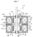
- Fig. 7 is a sectional view of a two phase PM type stepping motor 1 similar to that of Fig. 1.
- the components and positions which are the same as those of the first embodiment are indicated by the same reference numerals, and a description thereof will be omitted.
- the circumferential positional relationship of the stator teeth 25 and 26 is set according to formulas (6) and (7), formulas (8) and (9), formulas (12) and (13), and formulas (14) and (15) as in the first and second embodiments described above.
- a disc-like spacer 40 is provided between the first stator unit 21A and the second stator unit 21B. However, at the center of the spacer 40, there is formed a circular opening 40a having a diameter approximately the same as the diameter d of the plate portion 24a of the inner yoke 24 (see Fig. 8), whereby, as shown in Fig. 9. the spacer 40 is only in contact with the plate portion 24a of the inner yoke 24, and is not in contact with the base portions of the stator teeth 26.
- the plate portions 23b of the outer yokes 23 are in contact with the covers 30A and 30B, respectively, and of the portion in contact with the covers 30A and 30B, a welding point w is set at the base portions of the stator teeth 25, and spot welding is performed at the welding point w to join the base portions of the stator teeth 25 to the cover 30A and 30B, respectively. More specifically, in this embodiment, as shown in Fig. 10, a welding point w is set at every other base portion of the stator teeth 25 to perform spot welding, whereby the stator teeth 25 are not easily detached from the covers 30A and 30B.
- the second reason is that a gap 41 is formed. That is, even if the stator teeth 26 of the inner yoke 24 axially vibrate due to the electromagnetic force when the motor 1 is driven, it is possible, due to the formation of the gap 41, to avoid collision of the stator teeth 26 on the first stator unit 21A side with the stator teeth 26 on the second stator unit 21B side. Further, by reducing the contact portion of the inner yokes 24, it is possible to reduce the magnetic interference between the first and second stator units 21A and 21B, so that it is possible to prevent fluctuation in electromagnetic force or unevenness in rotation attributable thereto.
- stator teeth 25 are not easily separated from the covers 30A and 30B. That is, even if an axial force is exerted on the stator teeth 25 of the outer yoke 23 due to the electromagnetic force when the motor 1 is driven, the stator teeth 25 cannot collide with the covers 30A and 30B when returning to the original positions as long as the stator teeth 25 are not separated from the covers 30A and 30B.
- this embodiment it is possible to reduce higher harmonic components of the detent torque due to an action similar to that of the first and second embodiments and, further, to reduce the vibration caused by the force axially vibrating the stator teeth 25 and 26 due to the electromagnetic force when the motor 1 is driven, so that it is advantageously possible to achieve a very quiet and smooth rotation.
- the construction in which the base portions of the stator teeth 25 of the outer yoke 23 are joined to the covers 30A and 30B by welding corresponds to the structure for preventing collision with the cover.
- the gap 41 is formed by utilizing the spacer 40, this should not be construed restrictively. It is also possible to form the gap 41 by deforming the base portions of the stator teeth 26 in the direction away from the adjacent inner yoke 24. More specifically, as shown, for example, in Fig. 11(a), the gap 41 may be formed by deforming the base portions of the stator teeth 26 in a step-like manner, or as shown in Fig. 11(b), the gap 41 may be formed by bending the base portions of the stator teeth 26.
- the configurations as shown in Fig. 11(a) and 11(b) can be easily obtained when forming the inner yoke 24 by pressing, so that no increase in production cost is involved.
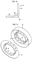
- Fig. 12 is a perspective view of one stator tooth 26 of the inner yoke 24 and the plate portion 24a in the vicinity thereof
- Fig. 13 is a perspective view as seen from the opposite direction
- Fig. 14 is a side view of the same portion.
- Ribs 42a, 42b and 42c extending along the radial direction of the inner yoke 24 are integrally formed at the center and on both sides of the base portion of the stator tooth 26 by pressing. It is possible to adopt a similar construction for the stator teeth 25 of the outer yoke 23.
- stator teeth 25 and 26 when the ribs 42a, 42b and 42c are formed on the stator teeth 25 and 26, even if a force causing axial vibration of the stator teeth 25 and 26 is generated due to the electromagnetic force when the motor 1 is driven, it is possible to eliminate or minimize the vibration of the stator teeth 25 and 26, so that it is possible to prevent the stator teeth 25 and 26 from colliding with the covers 30A and 30B and other stator teeth 26 close thereto or minimize the impact, and it is possible to eliminate or minimize the noise.
- the ribs 42a, 42b and 42c are integrally formed by stamping, so that unlike the construction in which separate members are fastened afterwards, no increase in production cost is involved.
- Figs. 15 through 17 show the fourth embodiment of the present invention.
- Fig. 15 is a perspective view of the outer yoke 23 and the inner yoke 24.
- the general construction of the PM type stepping motor of this embodiment is the same as that of the first embodiment, so it is not shown in the drawing and a description thereof will be omitted.
- the components and positions which are the same as those of the first embodiment are indicated by the same reference numerals, and a description thereof will be omitted.
- a ring 27 serving as a restraining member for restraining outward and radial deformation of the stator teeth 25, and due to this ring 27, outward deformation of the stator teeth 26 of the inner yoke 24 is also restrained. That is, the ring 27 is formed of a non-magnetic material, such as aluminum or brass, and, as shown in the sectional view of Fig.
- the width of the ring is such that when the ring 27 is attached to the stator teeth 25 of the outer yoke 23 and the inner yoke 24, it covers the axial length from the forward ends of the stator teeth 25 of the outer yoke 23 to the forward ends of the stator teeth 26 of the inner yoke 24 and, the wall thickness of the ring is such that when the ring 27 is attached to the stator teeth 25 and 26, a margin is left between the ring 27 and the exciting coil 22, and that outward deformation of the stator teeth 25 and 26 can be restrained.
- the stator teeth 26 of the inner yoke 24 are forced into this ring 27, whereby the ring 27 is attached to the stator teeth 25 of the outer yoke 23 and the stator teeth 26 of the inner yoke 24.
- stator teeth 25 and 26 When an electromagnetic force acting radially or axially when the motor is driven is applied to the stator teeth 25 and 26, due to the low stiffness of these stator teeth 25 and 26, the stator teeth 25 and 26 are deformed radially outward each time there is a change in the opposed positions of the magnetic pole of the rotor 10 and the stator teeth 25 and 26 to thereby also cause axial deformation, thereby generating vibration and causing noise. That is, as compared with the case in which the motor is not driven as shown in Fig. 17(a), in the case when the motor is driven as shown in Fig. 17(b), the stator teeth are deformed radially outward, and the nearer the forward end, the greater the deformation. While Fig. 17(b) only shows the stator teeth of one of the inner and outer yokes, this phenomenon is in fact observed with the stator teeth 25 and 26 of both the outer yoke 23 and the inner yoke 24.
- the ring 27 which is engaged with the portions near the forward ends of the stator teeth 25 and 26, so that it is possible to restrain the radial and outward deformation of the stator teeth 25 and 26.
- the deformation of the stator teeth 25 and 26 is restrained, so that the vibration due to the deformation of the stator teeth 25 and 26 is also restrained.
- the deformation of the stator teeth 25 and 26 might be restrained, for example, by filling the gap between the stator teeth 25 and 26 and the exciting coil 22 with resin or the like, or embedding metal.
- resin has low rigidity, and it is necessary to fill the whole gap between the stator teeth 25 and 26 and the exciting coil 22 with resin to fix the teeth, with the result that the assembly takes much time.
- the method of embedding metal is difficult from the viewpoint of production.
- an inadvertent stress could be applied to the stator teeth 25 and 26.
- the ring 27 is formed so as to leave a margin between it and the exciting coil 22, it is easy to perform the assembly even when mounting the stator teeth 25 and 26 and the exciting coil 22.
- the amount of deformation is larger at the forward ends of the stator teeth 25 and 26 than at the base portions thereof.
- a ring is provided in the vicinity of the forward ends of the stator teeth 25 and 26, which means the ring 27 is provided where the amount of deformation of the stator teeth 25 and 26 is maximum, whereby it is possible to effectively restrain the deformation of the stator teeth 25 and 26.
- stator teeth 25 and 26 of both the outer yoke 23 and the inner yoke 24 are constrained, this should not be construed restrictively. It is also possible to provide two rings: a ring for constraining the stator teeth 25 of the outer yoke 23 and a ring for constraining the stator teeth 26 of the inner yoke 24. However, by constraining the stator teeth 25 and 26 of both the outer yoke 23 and the inner yoke 24 by the same ring 27, it is possible to restrain the increase in the number of parts of the motor to a minimum level.
- the ring 27 is provided as the constraining member for the stator teeth 25 and 26, it is not absolutely necessary for the constraining member to be in the form of a ring.
- the constraining member may be a member in the form of a coil, and any type of member is applicable as long as it is capable of restraining the deformation of the stator teeth 25 and 26.
- the wall thickness of the ring 27 is such that a space is left between the ring 27 and the exciting coil 22 when the ring 27 is attached to the stator teeth 25 and 26, leaving such space is not absolutely necessary; it is only necessary for the wall thickness to be slightly smaller than the distance between the ring 27 and the exciting coil 22.
- the essential thing is that the wall thickness be such that when assembling the stator teeth 25 and 26 and the exciting coil 22, the assembly can be easily performed even when the ring 27 is attached.
- a ring 27 is used that covers the forward ends of the stator teeth 25 and 26, it is not absolutely necessary for the ring to cover up to the forward ends; it suffices to cover the portions near the forward ends so that the deformation of the stator teeth 25 and 26 can be restrained.
- the present invention is applied to a two phase PM type stepping motor 1, the field of application of the present invention is not restricted to this.
- the present invention is also applicable to a PM type stepping motor of one phase or three or more phases.
- the pitches P2 and P3 are set so as to aim at a reduction in the fourth-degree higher harmonic component of the detent torque or the second-degree higher harmonic component and the fourth-degree higher harmonic component of the detent torque, this should not be construed restrictively.
- a three phase PM type stepping motor it is possible to adopt a construction in which the fourth-degree higher harmonic component and the sixth-degree higher harmonic component can be reduced, and, in the case of a four phase PM type stepping motor, it is possible to adopt a construction in which the fourth-degree higher harmonic component and the eighth-degree higher harmonic component can be reduced, and the selection can be arbitrarily effected.
- the pitch P2 of the stator teeth in the teeth groups and the pitch P3 of the teeth groups are appropriately set, so that harmonic components of higher degree can be reduced, whereby these higher harmonics can be efficiently reduced and a more quiet and smooth rotation can be achieved.
Landscapes
- Engineering & Computer Science (AREA)
- Power Engineering (AREA)
- Iron Core Of Rotating Electric Machines (AREA)
Applications Claiming Priority (4)
| Application Number | Priority Date | Filing Date | Title |
|---|---|---|---|
| JP26939399 | 1999-09-22 | ||
| JP26939399 | 1999-09-22 | ||
| JP2000149715A JP3978980B2 (ja) | 1999-09-22 | 2000-05-22 | Pm形ステッピングモータ |
| JP2000149715 | 2000-05-22 |
Publications (3)
| Publication Number | Publication Date |
|---|---|
| EP1087502A2 true EP1087502A2 (de) | 2001-03-28 |
| EP1087502A3 EP1087502A3 (de) | 2003-01-02 |
| EP1087502B1 EP1087502B1 (de) | 2005-08-24 |
Family
ID=26548744
Family Applications (1)
| Application Number | Title | Priority Date | Filing Date |
|---|---|---|---|
| EP00120745A Expired - Lifetime EP1087502B1 (de) | 1999-09-22 | 2000-09-22 | Dauermagnet-Schrittmotor |
Country Status (5)
| Country | Link |
|---|---|
| US (1) | US6479911B1 (de) |
| EP (1) | EP1087502B1 (de) |
| JP (1) | JP3978980B2 (de) |
| CN (1) | CN100392960C (de) |
| DE (1) | DE60022143T2 (de) |
Cited By (6)
| Publication number | Priority date | Publication date | Assignee | Title |
|---|---|---|---|---|
| US6486576B1 (en) * | 1999-09-30 | 2002-11-26 | Sanyo Denki Co., Ltd. | Permanent magnet type stepping motor |
| WO2003030332A3 (de) * | 2001-09-25 | 2003-11-13 | Minebea Co Ltd | Elektromotor, insbesondere elektronisch kommutierter gleichstrommotor |
| WO2007144966A1 (ja) | 2006-06-14 | 2007-12-21 | Shinsei Seiki Co., Ltd. | インダクタ型モータ、及びインダクタ型モータの製造方法 |
| CN102130544A (zh) * | 2011-03-05 | 2011-07-20 | 杨学勤 | 高效发电机的制作方法和高效多转子多定子交互式发电机 |
| WO2011135268A1 (fr) * | 2010-04-28 | 2011-11-03 | Federal Mogul Sintertech | Phase de moteur homopolaire. |
| EP2696482A3 (de) * | 2012-08-09 | 2017-01-18 | Minebea Co. Ltd. | Klauenpolmotor |
Families Citing this family (22)
| Publication number | Priority date | Publication date | Assignee | Title |
|---|---|---|---|---|
| EP1221757A1 (de) * | 2001-01-09 | 2002-07-10 | Alps Electric Co., Ltd. | Dünner Motor mit Innenrotor zum Antrieb eines Aufzeichnungsmediums und Plattengerät mit diesem Motor |
| JP4828043B2 (ja) * | 2001-05-31 | 2011-11-30 | ミネベア株式会社 | Pm型ステッピングモータ |
| US7164216B2 (en) * | 2003-07-23 | 2007-01-16 | Nidec Sankyo Corporation | Motor |
| US20050275303A1 (en) * | 2004-06-09 | 2005-12-15 | Tetmeyer Michael E | Differential flux permanent magnet machine |
| JP4543793B2 (ja) * | 2004-07-09 | 2010-09-15 | 株式会社デンソー | 交流モータおよびその制御装置 |
| JP4656913B2 (ja) | 2004-11-02 | 2011-03-23 | 日本電産サーボ株式会社 | 多相クローポール形回転電機 |
| DE112006001327B8 (de) * | 2005-05-24 | 2016-09-01 | Denso Corporation | Mehrphasiger Elektromotor |
| JP4376863B2 (ja) * | 2005-12-22 | 2009-12-02 | シナノケンシ株式会社 | 永久磁石型回転機 |
| JP4604064B2 (ja) * | 2007-06-19 | 2010-12-22 | 日立オートモティブシステムズ株式会社 | 車両用交流発電機及び回転電機 |
| DE102008057349B3 (de) * | 2008-11-14 | 2010-07-15 | Feaam Gmbh | Elektrische Maschine |
| CN101990735B (zh) * | 2009-03-18 | 2014-02-19 | 日本电产三协株式会社 | 步进电动机 |
| DE202009017422U1 (de) * | 2009-06-26 | 2010-11-04 | Robert Bosch Gmbh | Handgeführtes Elektrowerkzeug |
| US20130134803A1 (en) | 2010-03-05 | 2013-05-30 | Andreas Kappel | Electromechanical motor |
| JP5510079B2 (ja) * | 2010-06-02 | 2014-06-04 | 富士電機株式会社 | アキシャルギャップモータ |
| CN102035349B (zh) * | 2010-12-03 | 2013-01-16 | 宁波精芯科技有限公司 | 一种热敏打印机 |
| CN103378708B (zh) * | 2012-04-23 | 2017-08-08 | 德昌电机(深圳)有限公司 | 步进电机及使用该步进电机的线性驱动器 |
| JP2015082942A (ja) * | 2013-10-24 | 2015-04-27 | ミネベア株式会社 | Pm型ステッピングモータ |
| JP6427333B2 (ja) * | 2014-04-16 | 2018-11-21 | 株式会社不二工機 | 電磁的駆動コイル装置の成形方法 |
| CN105610258B (zh) * | 2015-10-26 | 2018-01-30 | 湖南省金函数科技有限公司 | 一种永磁步进伺服电机 |
| CN106849600A (zh) * | 2017-03-31 | 2017-06-13 | 深圳市正德智控股份有限公司 | 一种步进电机 |
| CN211830366U (zh) * | 2020-03-06 | 2020-10-30 | 瑞声通讯科技(常州)有限公司 | 一种步进电机 |
| WO2025245670A1 (zh) * | 2024-05-27 | 2025-12-04 | 瑞声光电科技(常州)有限公司 | 步进电机 |
Family Cites Families (26)
| Publication number | Priority date | Publication date | Assignee | Title |
|---|---|---|---|---|
| US2548633A (en) * | 1947-08-28 | 1951-04-10 | Gen Electric | Dynamoelectric machine |
| US3633055A (en) * | 1970-06-22 | 1972-01-04 | Molon Motor & Coil Corp | Permanent magnet motor |
| GB1398364A (en) * | 1972-09-14 | 1975-06-18 | Eheim G | Motor and pump combination |
| DE2816098C2 (de) * | 1978-04-13 | 1980-04-17 | Sodeco-Saia Ag, Genf (Schweiz) | Kleinelektromotor |
| GB2066417A (en) * | 1979-11-21 | 1981-07-08 | Heidolph Elektro Kg | An Arrangement for Absorbing the Axial Vibrations of Rotors Supported in Sliding Bearings |
| US4672247A (en) * | 1984-12-27 | 1987-06-09 | North American Philips Corporation | Synchronous or stepping motor with equal-torque stepping |
| US4794292A (en) * | 1986-07-21 | 1988-12-27 | Canon Kabushiki Kaisha | Stepping motor with divided stator pole pieces |
| JPH01283049A (ja) * | 1988-05-10 | 1989-11-14 | Oki Electric Ind Co Ltd | パルスモータ |
| JPH037050A (ja) | 1989-05-31 | 1991-01-14 | Seiko Epson Corp | Pm型ステッピングモータのヨーク構造 |
| JPH03143298A (ja) * | 1989-10-25 | 1991-06-18 | Brother Ind Ltd | ステッピングモータの制御方式 |
| JP2581261B2 (ja) * | 1990-04-27 | 1997-02-12 | ブラザー工業株式会社 | ステップモータ |
| JPH0439078U (de) * | 1990-07-25 | 1992-04-02 | ||
| DE69108645T2 (de) | 1990-08-27 | 1995-10-26 | Canon Kk | Schrittmotor und Verfahren zum Betrieb eines solchen Motors. |
| JPH0576163A (ja) * | 1991-09-12 | 1993-03-26 | Seiko Instr Inc | ステツピングモータ |
| JPH05252719A (ja) | 1992-02-29 | 1993-09-28 | Sony Corp | ステツピングモータ |
| JPH0614515A (ja) * | 1992-06-23 | 1994-01-21 | Sony Corp | ステツピングモータ |
| JP3060358B2 (ja) * | 1994-06-24 | 2000-07-10 | 富士電気化学株式会社 | ステータヨークの製造方法及びステータヨーク |
| JPH0851754A (ja) * | 1994-08-05 | 1996-02-20 | Nippondenso Co Ltd | 2相pm型ステッピングモータ |
| JPH08126290A (ja) | 1994-10-20 | 1996-05-17 | Fuji Elelctrochem Co Ltd | ヨークの接合方法 |
| JP3360460B2 (ja) * | 1995-01-23 | 2002-12-24 | セイコーエプソン株式会社 | ステッピングモーター |
| JPH08242572A (ja) * | 1995-02-28 | 1996-09-17 | Japan Servo Co Ltd | 3相永久磁石式回転電機 |
| JPH09233802A (ja) | 1996-02-28 | 1997-09-05 | Sankyo Seiki Mfg Co Ltd | モータ |
| JP3460912B2 (ja) * | 1996-10-18 | 2003-10-27 | ミネベア株式会社 | モータ構造 |
| JP3422192B2 (ja) | 1996-10-25 | 2003-06-30 | セイコーエプソン株式会社 | Pm形ステッピングモータ |
| JP2000253644A (ja) * | 1998-12-28 | 2000-09-14 | Sankyo Seiki Mfg Co Ltd | モータ |
| JP2000224832A (ja) * | 1999-01-27 | 2000-08-11 | Sanyo Denki Co Ltd | 永久磁石型ステッピングモータ |
-
2000
- 2000-05-22 JP JP2000149715A patent/JP3978980B2/ja not_active Expired - Fee Related
- 2000-09-07 US US09/657,364 patent/US6479911B1/en not_active Expired - Lifetime
- 2000-09-21 CN CNB001286986A patent/CN100392960C/zh not_active Expired - Fee Related
- 2000-09-22 DE DE60022143T patent/DE60022143T2/de not_active Expired - Lifetime
- 2000-09-22 EP EP00120745A patent/EP1087502B1/de not_active Expired - Lifetime
Cited By (10)
| Publication number | Priority date | Publication date | Assignee | Title |
|---|---|---|---|---|
| US6486576B1 (en) * | 1999-09-30 | 2002-11-26 | Sanyo Denki Co., Ltd. | Permanent magnet type stepping motor |
| WO2003030332A3 (de) * | 2001-09-25 | 2003-11-13 | Minebea Co Ltd | Elektromotor, insbesondere elektronisch kommutierter gleichstrommotor |
| US7002275B2 (en) | 2001-09-25 | 2006-02-21 | Minebea Co., Ltd. | Electric motor, particularly an electronically commutated direct current motor |
| WO2007144966A1 (ja) | 2006-06-14 | 2007-12-21 | Shinsei Seiki Co., Ltd. | インダクタ型モータ、及びインダクタ型モータの製造方法 |
| EP2040357A4 (de) * | 2006-06-14 | 2011-09-14 | Shinsei Seiki Co Ltd | Induktor-motor und verfahren zur herstellung eines induktor-motors |
| WO2011135268A1 (fr) * | 2010-04-28 | 2011-11-03 | Federal Mogul Sintertech | Phase de moteur homopolaire. |
| FR2961037A1 (fr) * | 2010-04-28 | 2011-12-09 | Francecol Technology | Realisation d'une phase de machine homopolaire tournante, applique a la conception de son circuit magnetique |
| US9337710B2 (en) | 2010-04-28 | 2016-05-10 | Sintertech | Homopolar motor phase |
| CN102130544A (zh) * | 2011-03-05 | 2011-07-20 | 杨学勤 | 高效发电机的制作方法和高效多转子多定子交互式发电机 |
| EP2696482A3 (de) * | 2012-08-09 | 2017-01-18 | Minebea Co. Ltd. | Klauenpolmotor |
Also Published As
| Publication number | Publication date |
|---|---|
| US6479911B1 (en) | 2002-11-12 |
| EP1087502B1 (de) | 2005-08-24 |
| CN1289169A (zh) | 2001-03-28 |
| EP1087502A3 (de) | 2003-01-02 |
| DE60022143T2 (de) | 2006-06-01 |
| JP3978980B2 (ja) | 2007-09-19 |
| CN100392960C (zh) | 2008-06-04 |
| JP2001161055A (ja) | 2001-06-12 |
| DE60022143D1 (de) | 2005-09-29 |
Similar Documents
| Publication | Publication Date | Title |
|---|---|---|
| EP1087502B1 (de) | Dauermagnet-Schrittmotor | |
| US9130441B2 (en) | Brushless DC motor | |
| US5780944A (en) | Two-phase permanent-magnet electric rotating machine | |
| JPWO2015029256A1 (ja) | 同期電動機 | |
| WO2007043506A1 (ja) | 2つのロータを有するモータ | |
| US6781260B2 (en) | Permanent magnet type rotary machine | |
| JP2019088033A (ja) | 電機子 | |
| CN108933510B (zh) | 自行车用发电装置 | |
| CN210780261U (zh) | 定子铁芯和马达 | |
| JP2005094901A (ja) | ブラシレスモータ | |
| JP2002112521A (ja) | ステップモータのロータ構造 | |
| JP2011097756A (ja) | ステッピングモータのステータヨークおよびステッピングモータ | |
| WO2003069766A1 (fr) | Moteur pas-a-pas plat | |
| JP2019030154A (ja) | ステータおよびモータ | |
| JPH08256461A (ja) | 永久磁石形モータ | |
| JP3410519B2 (ja) | 3相クロ−ポ−ル式永久磁石型回転電機 | |
| JP4770434B2 (ja) | モータ | |
| JP2018074882A (ja) | ランデル型モータ及びランデル型モータの製造方法 | |
| JP2006288012A (ja) | アキシャルギャップ型電動機 | |
| JP7278162B2 (ja) | ステッピングモータ | |
| JP6122794B2 (ja) | Pm型ステッピングモータ | |
| JPH09117123A (ja) | ステッピングモータ | |
| KR101551628B1 (ko) | 스텝 진동 모터 | |
| US9985510B2 (en) | PM stepping motor | |
| WO2025115064A1 (ja) | 回転電機 |
Legal Events
| Date | Code | Title | Description |
|---|---|---|---|
| PUAI | Public reference made under article 153(3) epc to a published international application that has entered the european phase |
Free format text: ORIGINAL CODE: 0009012 |
|
| AK | Designated contracting states |
Kind code of ref document: A2 Designated state(s): AT BE CH CY DE DK ES FI FR GB GR IE IT LI LU MC NL PT SE |
|
| AX | Request for extension of the european patent |
Free format text: AL;LT;LV;MK;RO;SI |
|
| PUAL | Search report despatched |
Free format text: ORIGINAL CODE: 0009013 |
|
| PUAF | Information related to the publication of a search report (a3 document) modified or deleted |
Free format text: ORIGINAL CODE: 0009199SEPU |
|
| AK | Designated contracting states |
Kind code of ref document: A3 Designated state(s): AT BE CH CY DE DK ES FI FR GB GR IE IT LI LU MC NL PT SE |
|
| AX | Request for extension of the european patent |
Free format text: AL;LT;LV;MK;RO;SI |
|
| D17D | Deferred search report published (deleted) | ||
| PUAL | Search report despatched |
Free format text: ORIGINAL CODE: 0009013 |
|
| RIC1 | Information provided on ipc code assigned before grant |
Ipc: 7H 02K 21/14 B Ipc: 7H 02K 1/14 B Ipc: 7H 02K 37/14 A Ipc: 7H 02K 5/167 B |
|
| AK | Designated contracting states |
Kind code of ref document: A3 Designated state(s): AT BE CH CY DE DK ES FI FR GB GR IE IT LI LU MC NL PT SE |
|
| AX | Request for extension of the european patent |
Extension state: AL LT LV MK RO SI |
|
| 17P | Request for examination filed |
Effective date: 20031016 |
|
| 17Q | First examination report despatched |
Effective date: 20040225 |
|
| AKX | Designation fees paid |
Designated state(s): DE FR GB |
|
| GRAP | Despatch of communication of intention to grant a patent |
Free format text: ORIGINAL CODE: EPIDOSNIGR1 |
|
| GRAS | Grant fee paid |
Free format text: ORIGINAL CODE: EPIDOSNIGR3 |
|
| GRAA | (expected) grant |
Free format text: ORIGINAL CODE: 0009210 |
|
| AK | Designated contracting states |
Kind code of ref document: B1 Designated state(s): DE FR GB |
|
| REG | Reference to a national code |
Ref country code: GB Ref legal event code: FG4D |
|
| REF | Corresponds to: |
Ref document number: 60022143 Country of ref document: DE Date of ref document: 20050929 Kind code of ref document: P |
|
| ET | Fr: translation filed | ||
| PLBE | No opposition filed within time limit |
Free format text: ORIGINAL CODE: 0009261 |
|
| STAA | Information on the status of an ep patent application or granted ep patent |
Free format text: STATUS: NO OPPOSITION FILED WITHIN TIME LIMIT |
|
| 26N | No opposition filed |
Effective date: 20060526 |
|
| PGFP | Annual fee paid to national office [announced via postgrant information from national office to epo] |
Ref country code: DE Payment date: 20140917 Year of fee payment: 15 |
|
| PGFP | Annual fee paid to national office [announced via postgrant information from national office to epo] |
Ref country code: GB Payment date: 20140917 Year of fee payment: 15 |
|
| PGFP | Annual fee paid to national office [announced via postgrant information from national office to epo] |
Ref country code: FR Payment date: 20140906 Year of fee payment: 15 |
|
| REG | Reference to a national code |
Ref country code: DE Ref legal event code: R119 Ref document number: 60022143 Country of ref document: DE |
|
| GBPC | Gb: european patent ceased through non-payment of renewal fee |
Effective date: 20150922 |
|
| REG | Reference to a national code |
Ref country code: FR Ref legal event code: ST Effective date: 20160531 |
|
| PG25 | Lapsed in a contracting state [announced via postgrant information from national office to epo] |
Ref country code: DE Free format text: LAPSE BECAUSE OF NON-PAYMENT OF DUE FEES Effective date: 20160401 Ref country code: GB Free format text: LAPSE BECAUSE OF NON-PAYMENT OF DUE FEES Effective date: 20150922 |
|
| PG25 | Lapsed in a contracting state [announced via postgrant information from national office to epo] |
Ref country code: FR Free format text: LAPSE BECAUSE OF NON-PAYMENT OF DUE FEES Effective date: 20150930 |