EP1092603B1 - Dispositif d'essuie-glace - Google Patents
Dispositif d'essuie-glace Download PDFInfo
- Publication number
- EP1092603B1 EP1092603B1 EP99203311A EP99203311A EP1092603B1 EP 1092603 B1 EP1092603 B1 EP 1092603B1 EP 99203311 A EP99203311 A EP 99203311A EP 99203311 A EP99203311 A EP 99203311A EP 1092603 B1 EP1092603 B1 EP 1092603B1
- Authority
- EP
- European Patent Office
- Prior art keywords
- yoke
- shaped cross
- section
- secondary yoke
- wiper device
- Prior art date
- Legal status (The legal status is an assumption and is not a legal conclusion. Google has not performed a legal analysis and makes no representation as to the accuracy of the status listed.)
- Expired - Lifetime
Links
Images

Classifications
-
- B—PERFORMING OPERATIONS; TRANSPORTING
- B60—VEHICLES IN GENERAL
- B60S—SERVICING, CLEANING, REPAIRING, SUPPORTING, LIFTING, OR MANOEUVRING OF VEHICLES, NOT OTHERWISE PROVIDED FOR
- B60S1/00—Cleaning of vehicles
- B60S1/02—Cleaning windscreens, windows or optical devices
- B60S1/04—Wipers or the like, e.g. scrapers
- B60S1/32—Wipers or the like, e.g. scrapers characterised by constructional features of wiper blade arms or blades
- B60S1/38—Wiper blades
- B60S1/3801—Wiper blades characterised by a blade support harness consisting of several articulated elements
-
- B—PERFORMING OPERATIONS; TRANSPORTING
- B60—VEHICLES IN GENERAL
- B60S—SERVICING, CLEANING, REPAIRING, SUPPORTING, LIFTING, OR MANOEUVRING OF VEHICLES, NOT OTHERWISE PROVIDED FOR
- B60S1/00—Cleaning of vehicles
- B60S1/02—Cleaning windscreens, windows or optical devices
- B60S1/04—Wipers or the like, e.g. scrapers
- B60S1/32—Wipers or the like, e.g. scrapers characterised by constructional features of wiper blade arms or blades
- B60S1/38—Wiper blades
- B60S2001/3812—Means of supporting or holding the squeegee or blade rubber
- B60S2001/3813—Means of supporting or holding the squeegee or blade rubber chacterised by a support harness consisting of several articulated elements
- B60S2001/3815—Means of supporting or holding the squeegee or blade rubber chacterised by a support harness consisting of several articulated elements chacterised by the joint between elements
Definitions
- the invention relates to a windscreen wiper device comprising an oscillating arm and a frame connected thereto for receiving a wiper blade, which frame includes a secondary yoke which is pivotally connected to a first yoke about a pivot axis, wherein both the first yoke and the secondary yoke are of at least substantially U-shaped cross section at the location of their interconnection, and wherein said secondary yoke is positioned at least substantially within said first yoke.
- each leg of the U-shaped cross section of the secondary yoke includes a protrusion at the location of the pivot axis, which protrusion extends into a corresponding through hole in one of the legs of the U-shaped cross section of the first yoke in the operating condition. In said operating condition, the secondary yoke pivots about a pivot axis relative to the first yoke.
- the secondary yoke Before the operating condition is reached, the secondary yoke is first placed into the first yoke, whereby the legs of the U-shaped cross section of the first yoke occupy an initial position, that is, extend outwards relative to the secondary yoke. Then the legs of the U-shaped cross section of the first yoke are bent inwards by exerting an external force in inward direction relative to the secondary yoke, wherein the protrusions of the secondary yoke extend into the corresponding through holes in the first yoke. The legs of the U-shaped cross section of the first yoke remain in said bent position, thus securing the operating position.
- the object of the invention is to overcome the above drawbacks of the prior art and in particular to provide a windscreen wiper device wherein the connection between the secondary yoke and the first yoke is durable and solid, i.e. wherein particularly there is no angular play between the first yoke and the secondary yoke.
- a windscreen wiper device of the kind mentioned in the introduction is according to the invention characterized in that the first yoke includes a closed substantially cylindrical protuberance in each leg of the U-shaped cross section at the location of the pivot axis, which protuberance forms a substantially cylindrical bearing surface.
- the protuberances extend outwards on either side relative to the secondary yoke, the secondary yoke being provided at the location of the pivot axis with a protrusion in each leg of its U-shaped cross section, which protrusion pivotally engages in a corresponding protuberance of the first yoke, wherein said first yoke is made of a metal and wherein said secondary yoke is made of plastic material.
- the protuberances extend outwards, the two protrusions of the secondary yoke, which function as bearing supports, are spaced relatively far apart, as a result of which the forces on said bearings are relatively small.
- the protuberances extend inwards on either side relative to the secondary yoke, wherein the secondary yoke includes a recess in each leg of its U-shaped cross section, at the location of the pivot axis, in which a corresponding protuberance of the first yoke pivotally engages.
- the term "closed protuberance” is understood to mean a dished part, that is, a part of the material of the legs of the U-shaped cross section of the first yoke that is locally pushed aside, in such a manner that no opening in the sense of a through hole is formed.
- the material is pushed outwards, whilst in the latter preferred embodiment the material is pushed inwards.
- An important advantage of the closed protuberance or dished part is that the shape thereof can be determined with great precision by stamping or punching, so that there is no question of play between the secondary yoke and the first yoke. Another advantage is furthermore the fact that dirt from outside cannot accumulate in the protuberances.
- the secondary yoke is externally formed with a longitudinal groove in at least one leg of its U-shaped cross section, along which groove a protuberance of the first yoke is guided when the secondary yoke is at least substantially received in the first yoke in the longitudinal direction of the first yoke.
- the invention furthermore relates to a method of manufacturing a windscreen wiper device according to the invention, wherein the two closed protuberances are stamped in the sheet material from which the first yoke is made before the material is given its U-shaped section.
- the secondary yoke is placed at least substantially within the first yoke and connected thereto in an initial position, in which protrusions formed in the legs of the U-shaped cross section of the secondary yoke engage at least partially at the location of the pivot axis in protuberances of the first yoke extending outwards on either side relative to the secondary yoke, thus leaving some play between the secondary yoke and the first yoke, and wherein the secondary yoke is then connected to the first yoke in a final position, without play, by bending the legs of the U-shaped cross section of the first yoke inwardly relative to the secondary yoke.
- the secondary yoke is placed at least substantially within the first yoke and connected thereto in an initial position, wherein protuberances of the first yoke extending inwards on either side relative to the secondary yoke engage at least partially at the location of the pivot axis in recesses formed in the legs of the U-shaped cross section of the secondary yoke, thus leaving some play between the secondary yoke and the first yoke, and wherein the secondary yoke is then connected to the first yoke in a final position, without play, by bending the legs of the U-shaped cross section of the first yoke inwardly relative to the secondary yoke.
- the protuberances according to the invention are dimensioned such that, even when the legs of the U-shaped cross-section of the first yoke will spring back a little bit in outward direction relative to the secondary yoke after being bent in inward direction in the final position, angular play between the first yoke and the secondary yoke does not occur.
- British patent publication no. 2 055 561 discloses secondary yokes (1) comprising two laterally extending legs (4) having a rectangular shape.
- European patent publication no. 0 289 293 discloses a joint body (10) provided with trunnions (17) with a conical shape for engagement in recesses (9) of a secondary yoke (3).
- European patent publication no. 0 592 246 makes use of frusto conical connection means.
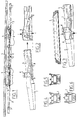
- Figures 1 and 7 show a perspective view of a wiper frame, which consists of a first yoke (1), which can be pivotally attached to an oscillating arm of a windscreen wiper device of a vehicle at the location of pivot axis (2).
- the first yoke (1) functions as the first yoke of two secondary yokes (3), which secondary yokes (3) function as the first yokes of two tertiary yokes (4).
- All yokes are pivot-mounted in their respective first yokes, so that a force exerted at the location of pivot axis (2) is distributed more or less evenly over the ends of the tertiary yokes (4), capable of being transferred to a rubber wiper blade (5), which can be fitted between the claws (6) of the tertiary yokes (4) and between the claws (7) of the secondary yokes (3).
- each yoke (3,4) and its respective first yoke (1,3) is effected without the interposition of a special separate joint part made of plastic material, for example, because only the first yoke (1) is made of metal and the other yokes (3,4) are made of plastic material. In case all yokes (1,3,4) are made of metal, such a special separate plastic joint part is used after all.
- Figures 2 and 8 show a perspective view on the manners the secondary yokes (3) are manoeuvred into the first yoke (1), wherein in accordance with figure 2 the secondary yokes (3) are slid inside the first yoke (1) in the longitudinal direction thereof, while according to figure 8 the secondary yokes (3) are brought inside the first yoke (1) in vertical direction, that is perpendicular to the first yoke (1). However, in both manners ( figures 2 and 8 ) the secondary yokes (3) are clipped into the first yoke in an initial position.
- FIGS 4, 5 and 6 are side views, whereas figure 5 is a partial cross-sectional side view.
- the aforesaid closed substantially cylindrical protuberances (8) are manufactured through a stamping or punching process, thereby accurately defining the shape thereof.
- the protuberances (8) are guided along grooves (10) on either side of the secondary yokes (3) in order to slide the latter inside the first yoke (1) in a controllable and easy manner.
- grooves (10) extend until the holes (9).
- the rubber wiper blade (5) is fixed to the frame ( figure 3 ).
- Figures 8-12 correspond to figures 2-6 on the understanding that figures 8-12 relate to the second embodiment, wherein the protuberances (8') extend outwards on either side relative to the secondary yokes (3). Therefore, the secondary yokes (3) are provided at the location of the pivot axis with protrusions (9') in the legs of the U-shaped cross section thereof.
Landscapes
- Engineering & Computer Science (AREA)
- Mechanical Engineering (AREA)
- Pivots And Pivotal Connections (AREA)
- Heat Treatment Of Strip Materials And Filament Materials (AREA)
- Power Steering Mechanism (AREA)
- Seal Device For Vehicle (AREA)
- Centrifugal Separators (AREA)
Claims (10)
- Dispositif à essuie-glace de pare-brise comprenant un bras oscillant et une armature reliée à celui-ci, qui permet de recevoir une lame d'essuie-glace (5), cette armature comprenant un collier secondaire (3) relié par pivot à un premier collier (1) autour d'un axe de pivot, dans lequel le premier collier (1) et le collier secondaire (3) ont une coupe transversale au moins sensiblement en forme de U à l'emplacement de leur interconnexion, et où ledit collier secondaire (3) est positionné au moins sensiblement à l'intérieur dudit premier collier (1), dans lequel ledit premier collier (1) est constitué d'un métal et où ledit collier secondaire (3) est constitué de matière plastique, caractérisé en ce que ledit premier collier (1) comprend une protubérance fermée (8, 8') sensiblement cylindrique dans chaque patte de la coupe transversale en forme de U, à l'emplacement de l'axe de pivot, cette protubérance (8, 8') formant une surface d'appui sensiblement cylindrique.
- Dispositif à essuie-glace selon la revendication 1, dans lequel lesdites protubérances (8') s'étendent vers l'extérieur de part et d'autre du collier secondaire (3).
- Dispositif à essuie-glace selon la revendication 2, dans lequel ledit collier secondaire (3) se trouve à l'emplacement de l'axe de pivot, avec une saillie (9') dans chaque patte de sa coupe transversale en forme de U, cette saillie (9') s'engageant à pivot dans une protubérance correspondante (8') du premier collier (1).
- Dispositif à essuie-glace selon la revendication 1, dans lequel lesdites protubérances (8) s'étendent vers l'intérieur de part et d'autre du collier secondaire (3).
- Dispositif à essuie-glace selon la revendication 4, dans lequel le collier secondaire (3) comprend un évidement (9) dans chaque patte de sa coupe transversale en forme de U, à l'emplacement de l'axe de pivot, dans lequel une protubérance correspondante (8) du premier collier (1) s'engage par pivot.
- Dispositif à essuie-glace selon l'une quelconque des revendications 1 à 5 précédentes, dans lequel ledit collier secondaire (3) est doté à l'extérieur d'une rainure longitudinale (10) située dans au moins une patte de sa coupe transversale en forme de U, rainure (10) le long de laquelle une protubérance (8) du premier collier (1) est guidée lorsque le collier secondaire (3) est reçu au moins sensiblement dans le premier collier (1) dans la direction longitudinale du premier collier (1).
- Procédé de fabrication d'un dispositif à essuie-glace selon l'une quelconque des revendications 1 à 6 précédentes, dans lequel les deux protubérances fermées (8, 8') sensiblement cylindriques sont estampées dans le matériau en tôle dont le premier collier (1) est constitué avant qu'on ne donne sa coupe transversale en forme de U à ce matériau.
- Procédé selon la revendication 7, dans lequel ledit collier secondaire (3) est placé au moins sensiblement à l'intérieur du premier collier (1) et relié à celui-ci en une position initiale, dans lequel des saillies (9') formées dans les pattes de la coupe transversale en forme de U du collier secondaire (3) s'engagent au moins en partie au niveau de l'emplacement de l'axe de pivot, dans des protubérances (8') du premier collier (1) s'étendant vers l'extérieur de part et d'autre du collier secondaire (3), ce qui laisse un certain jeu entre le collier secondaire (3) et le premier collier (1), et où le collier secondaire (3) est ensuite relié au premier collier (1) en une position finale, sans jeu, par déformation des pattes de la coupe transversale en forme de U du premier collier (1) vers l'intérieur par rapport au collier secondaire (3).
- Procédé selon la revendication 7, dans lequel ledit collier secondaire (3) est placé au moins sensiblement à l'intérieur du premier collier (1) et relié à celui-ci en une position initiale, dans lequel une protubérance (8) du premier collier (1), qui s'étend vers l'intérieur de part et d'autre du collier secondaire (3), s'engage au moins en partie à l'emplacement de l'axe de pivot dans des cavités (9) formées dans les pattes de la coupe transversale en forme de U du collier secondaire (3), ce qui laisse un certain jeu entre le collier secondaire (3) et le premier collier (1), et dans lequel le collier secondaire (3) est ensuite relié au premier collier (1) en une position finale, sans jeu, par déformation des pattes de la coupe transversale en forme de U du premier collier (1) vers l'intérieur par rapport au collier secondaire (3).
- Procédé selon la revendication 7, 8 ou 9, dans lequel une rainure longitudinale (10) est formée extérieurement dans au moins une patte de la coupe transversale en forme de U du collier secondaire (3), rainure (10) le long de laquelle une protubérance (8) du premier collier (1) est guidée lorsque le collier secondaire (3) est au moins sensiblement reçu dans le premier collier (1) suivant une direction longitudinale du premier collier (1).
Priority Applications (9)
| Application Number | Priority Date | Filing Date | Title |
|---|---|---|---|
| EP99203311A EP1092603B1 (fr) | 1999-10-11 | 1999-10-11 | Dispositif d'essuie-glace |
| ES99203311T ES2337318T3 (es) | 1999-10-11 | 1999-10-11 | Dispositivo limpiaparabrisas. |
| DE69941702T DE69941702D1 (de) | 1999-10-11 | 1999-10-11 | Scheibenwischervorrichtung |
| AT99203311T ATE449711T1 (de) | 1999-10-11 | 1999-10-11 | Scheibenwischervorrichtung |
| AU79163/00A AU7916300A (en) | 1999-10-11 | 2000-10-02 | Windscreen wiper device |
| CA002391801A CA2391801A1 (fr) | 1999-10-11 | 2000-10-02 | Dispositif d'essuie-glace |
| MXPA02003387A MXPA02003387A (es) | 1999-10-11 | 2000-10-02 | Dispositivo limpiador de parabrisas. |
| US10/110,357 US6820304B1 (en) | 1999-10-11 | 2000-10-02 | Windscreen wiper device |
| PCT/EP2000/009861 WO2001026942A1 (fr) | 1999-10-11 | 2000-10-02 | Dispositif d'essuie-glace |
Applications Claiming Priority (1)
| Application Number | Priority Date | Filing Date | Title |
|---|---|---|---|
| EP99203311A EP1092603B1 (fr) | 1999-10-11 | 1999-10-11 | Dispositif d'essuie-glace |
Publications (2)
| Publication Number | Publication Date |
|---|---|
| EP1092603A1 EP1092603A1 (fr) | 2001-04-18 |
| EP1092603B1 true EP1092603B1 (fr) | 2009-11-25 |
Family
ID=8240729
Family Applications (1)
| Application Number | Title | Priority Date | Filing Date |
|---|---|---|---|
| EP99203311A Expired - Lifetime EP1092603B1 (fr) | 1999-10-11 | 1999-10-11 | Dispositif d'essuie-glace |
Country Status (9)
| Country | Link |
|---|---|
| US (1) | US6820304B1 (fr) |
| EP (1) | EP1092603B1 (fr) |
| AT (1) | ATE449711T1 (fr) |
| AU (1) | AU7916300A (fr) |
| CA (1) | CA2391801A1 (fr) |
| DE (1) | DE69941702D1 (fr) |
| ES (1) | ES2337318T3 (fr) |
| MX (1) | MXPA02003387A (fr) |
| WO (1) | WO2001026942A1 (fr) |
Families Citing this family (25)
| Publication number | Priority date | Publication date | Assignee | Title |
|---|---|---|---|---|
| DE102006057024A1 (de) * | 2006-12-04 | 2008-06-05 | Robert Bosch Gmbh | Wischblatt |
| USD706200S1 (en) | 2010-09-22 | 2014-06-03 | Pylon Manufacturing Corporation | Windshield wiper cover |
| US9457768B2 (en) | 2011-04-21 | 2016-10-04 | Pylon Manufacturing Corp. | Vortex damping wiper blade |
| US9174609B2 (en) | 2011-04-21 | 2015-11-03 | Pylon Manufacturing Corp. | Wiper blade with cover |
| CA2843527C (fr) | 2011-07-28 | 2018-11-27 | Pylon Manufacturing Corp. | Adaptateur, raccord et ensemble d'essuie-glace |
| US9108595B2 (en) | 2011-07-29 | 2015-08-18 | Pylon Manufacturing Corporation | Windshield wiper connector |
| US8806700B2 (en) | 2011-07-29 | 2014-08-19 | Pylon Manufacturing Corporation | Wiper blade connector |
| WO2013019645A1 (fr) | 2011-07-29 | 2013-02-07 | Pylon Manufacturing Corp. | Connecteur d'essuie-glace |
| US20130219649A1 (en) | 2012-02-24 | 2013-08-29 | Pylon Manufacturing Corp. | Wiper blade |
| MX385411B (es) | 2012-02-24 | 2025-03-18 | Pylon Mfg Corp | Escobilla limpiaparabrisas. |
| US10723322B2 (en) | 2012-02-24 | 2020-07-28 | Pylon Manufacturing Corp. | Wiper blade with cover |
| US10829092B2 (en) | 2012-09-24 | 2020-11-10 | Pylon Manufacturing Corp. | Wiper blade with modular mounting base |
| US10166951B2 (en) | 2013-03-15 | 2019-01-01 | Pylon Manufacturing Corp. | Windshield wiper connector |
| US9505380B2 (en) | 2014-03-07 | 2016-11-29 | Pylon Manufacturing Corp. | Windshield wiper connector and assembly |
| CN106458162B (zh) * | 2014-07-03 | 2019-06-07 | 联邦莫古尔股份有限公司 | 风挡刮水器装置 |
| USD787308S1 (en) | 2014-10-03 | 2017-05-23 | Pylon Manufacturing Corp. | Wiper blade package |
| USD777079S1 (en) | 2014-10-03 | 2017-01-24 | Pylon Manufacturing Corp. | Wiper blade frame |
| US10363905B2 (en) | 2015-10-26 | 2019-07-30 | Pylon Manufacturing Corp. | Wiper blade |
| CN109311450A (zh) | 2016-05-19 | 2019-02-05 | 电缆塔制造有限公司 | 挡风玻璃雨刮器连接器 |
| AU2017268008A1 (en) | 2016-05-19 | 2018-11-22 | Pylon Manufacturing Corp. | Windshield wiper connector |
| US11040705B2 (en) | 2016-05-19 | 2021-06-22 | Pylon Manufacturing Corp. | Windshield wiper connector |
| CN109311452A (zh) | 2016-05-19 | 2019-02-05 | 电缆塔制造有限公司 | 挡风玻璃雨刮器连接器 |
| EP3458315B1 (fr) | 2016-05-19 | 2021-09-08 | Pylon Manufacturing Corp. | Balai d'essuie-glace |
| US11465590B2 (en) * | 2017-07-28 | 2022-10-11 | Pylon Manufacturing Corporation | Windshield wiper blade assembly |
| EP3826889B1 (fr) * | 2018-07-23 | 2023-09-06 | Trico Belgium S.A. | Dispositif d'essuie-glace du type à balai plat |
Family Cites Families (14)
| Publication number | Priority date | Publication date | Assignee | Title |
|---|---|---|---|---|
| GB2038167B (en) * | 1978-12-12 | 1983-03-02 | Trico Folberth Ltd | Windscrren wopers |
| FR2448460A1 (fr) * | 1979-02-12 | 1980-09-05 | Marchal Equip Auto | Essuie-glace, notamment pour vehicules automobiles |
| FR2453757A1 (fr) | 1979-04-12 | 1980-11-07 | Ducellier & Cie | Balai d'essuie-glace |
| CH631392A5 (fr) | 1979-08-08 | 1982-08-13 | J B Brevets | Balai d'essuie-glace. |
| FR2491847B1 (fr) * | 1980-10-15 | 1985-07-05 | Champion Spark Plug Europ | Element de liaison articulee pour balai d'essuie-glace |
| GB2139528B (en) | 1983-05-12 | 1986-04-09 | Trico Folberth Ltd | Method of assembling a trunnion joint for a wiper blade harness |
| GB8710341D0 (en) | 1987-04-30 | 1987-06-03 | Trico Folberth Ltd | Pivot joint |
| DE8808315U1 (de) * | 1988-06-29 | 1988-10-06 | Stinnes Technohandel GmbH & Co, 4100 Duisburg | Wischblatt, insbesondere für Kraftfahrzeuge |
| DE3838274A1 (de) * | 1988-11-11 | 1990-05-17 | Swf Auto Electric Gmbh | Wischblatt und verfahren zu seiner herstellung |
| GB9221261D0 (en) | 1992-10-09 | 1992-11-25 | Trico Ltd | Pivot joint |
| CA2118874C (fr) * | 1993-03-12 | 2001-05-29 | Tadao Kushida | Essuie-glace |
| DE69522105T2 (de) * | 1995-09-11 | 2002-04-11 | Cooper Automotive S.A., Aubange | Wischblatt und Verfahren zu dessen Herstellung |
| US5647087A (en) * | 1996-01-25 | 1997-07-15 | Nippon Wiperblade Co., Ltd. | Joint spacer for the yoke of a windshield wiper |
| FR2751597B1 (fr) * | 1996-07-29 | 1998-09-18 | Valeo Systemes Dessuyage | Essuie-glace de vehicule automobile a structure articulee perfectionnee |
-
1999
- 1999-10-11 DE DE69941702T patent/DE69941702D1/de not_active Expired - Lifetime
- 1999-10-11 ES ES99203311T patent/ES2337318T3/es not_active Expired - Lifetime
- 1999-10-11 EP EP99203311A patent/EP1092603B1/fr not_active Expired - Lifetime
- 1999-10-11 AT AT99203311T patent/ATE449711T1/de not_active IP Right Cessation
-
2000
- 2000-10-02 MX MXPA02003387A patent/MXPA02003387A/es active IP Right Grant
- 2000-10-02 CA CA002391801A patent/CA2391801A1/fr not_active Abandoned
- 2000-10-02 US US10/110,357 patent/US6820304B1/en not_active Expired - Lifetime
- 2000-10-02 AU AU79163/00A patent/AU7916300A/en not_active Abandoned
- 2000-10-02 WO PCT/EP2000/009861 patent/WO2001026942A1/fr not_active Ceased
Also Published As
| Publication number | Publication date |
|---|---|
| WO2001026942A1 (fr) | 2001-04-19 |
| ES2337318T3 (es) | 2010-04-22 |
| EP1092603A1 (fr) | 2001-04-18 |
| CA2391801A1 (fr) | 2001-04-19 |
| ATE449711T1 (de) | 2009-12-15 |
| AU7916300A (en) | 2001-04-23 |
| US6820304B1 (en) | 2004-11-23 |
| DE69941702D1 (de) | 2010-01-07 |
| MXPA02003387A (es) | 2004-09-10 |
Similar Documents
| Publication | Publication Date | Title |
|---|---|---|
| EP1092603B1 (fr) | Dispositif d'essuie-glace | |
| US7979950B2 (en) | Windscreen wiper device | |
| EP1681216B1 (fr) | Dispositif d'essuie-glace | |
| US5497673A (en) | Automatic transmission operating device | |
| EP0286231A1 (fr) | Balai d'essuie-glace | |
| KR950002506B1 (ko) | 피봇죠인트 | |
| GB2089199A (en) | Spacer for rotatably connecting wiper blade parts | |
| JPH0314905A (ja) | ピボット継手及びその製造方法 | |
| US5183352A (en) | Pivot joint | |
| JPS63172009A (ja) | ピボット継手 | |
| EP4139173B1 (fr) | Dispositif de balai d'essuie-glace du type à lame plate | |
| US5974620A (en) | Wiper blade and a method of manufacturing a wiper blade | |
| JPH011649A (ja) | ピボットジョイント | |
| US4909653A (en) | Pivot joint | |
| EP0747612A2 (fr) | Dispositif de changement de vitesse pour transmission | |
| US4009503A (en) | Wiper blade unit with fastening clip | |
| US5575175A (en) | Shift lever assembly | |
| GB2220844A (en) | Wiper blade | |
| US20110265306A1 (en) | Wiper Arm Assembly Having a Locking Arm and Method of Construction | |
| JP2671957B2 (ja) | ピポットジョイント | |
| US11040704B2 (en) | Windscreen wiper device | |
| KR101503758B1 (ko) | 다목적 차량과 같은 차량의 외부 후사경을 지지하기 위한 유지 힌지 부품 및 상기 유형의 유지 힌지 부품을 포함한 다목적 차량용 외부 후사경 | |
| GB2220843A (en) | Wiper blade | |
| EP3617558B1 (fr) | Dispositif de levier de vitesses | |
| JP4203069B2 (ja) | ワイパブレード |
Legal Events
| Date | Code | Title | Description |
|---|---|---|---|
| PUAI | Public reference made under article 153(3) epc to a published international application that has entered the european phase |
Free format text: ORIGINAL CODE: 0009012 |
|
| AK | Designated contracting states |
Kind code of ref document: A1 Designated state(s): AT BE CH CY DE DK ES FI FR GB GR IE IT LI LU MC NL PT SE |
|
| AX | Request for extension of the european patent |
Free format text: AL;LT;LV;MK;RO;SI |
|
| 17P | Request for examination filed |
Effective date: 20011015 |
|
| AKX | Designation fees paid |
Free format text: AT BE CH CY DE DK ES FI FR GB GR IE IT LI LU MC NL PT SE |
|
| GRAP | Despatch of communication of intention to grant a patent |
Free format text: ORIGINAL CODE: EPIDOSNIGR1 |
|
| GRAS | Grant fee paid |
Free format text: ORIGINAL CODE: EPIDOSNIGR3 |
|
| GRAA | (expected) grant |
Free format text: ORIGINAL CODE: 0009210 |
|
| AK | Designated contracting states |
Kind code of ref document: B1 Designated state(s): AT BE CH CY DE DK ES FI FR GB GR IE IT LI LU MC NL PT SE |
|
| REG | Reference to a national code |
Ref country code: GB Ref legal event code: FG4D |
|
| REG | Reference to a national code |
Ref country code: CH Ref legal event code: EP |
|
| REG | Reference to a national code |
Ref country code: IE Ref legal event code: FG4D |
|
| REF | Corresponds to: |
Ref document number: 69941702 Country of ref document: DE Date of ref document: 20100107 Kind code of ref document: P |
|
| REG | Reference to a national code |
Ref country code: NL Ref legal event code: VDEP Effective date: 20091125 |
|
| REG | Reference to a national code |
Ref country code: ES Ref legal event code: FG2A Ref document number: 2337318 Country of ref document: ES Kind code of ref document: T3 |
|
| PG25 | Lapsed in a contracting state [announced via postgrant information from national office to epo] |
Ref country code: SE Free format text: LAPSE BECAUSE OF FAILURE TO SUBMIT A TRANSLATION OF THE DESCRIPTION OR TO PAY THE FEE WITHIN THE PRESCRIBED TIME-LIMIT Effective date: 20091125 Ref country code: PT Free format text: LAPSE BECAUSE OF FAILURE TO SUBMIT A TRANSLATION OF THE DESCRIPTION OR TO PAY THE FEE WITHIN THE PRESCRIBED TIME-LIMIT Effective date: 20100325 Ref country code: FI Free format text: LAPSE BECAUSE OF FAILURE TO SUBMIT A TRANSLATION OF THE DESCRIPTION OR TO PAY THE FEE WITHIN THE PRESCRIBED TIME-LIMIT Effective date: 20091125 |
|
| PG25 | Lapsed in a contracting state [announced via postgrant information from national office to epo] |
Ref country code: CY Free format text: LAPSE BECAUSE OF FAILURE TO SUBMIT A TRANSLATION OF THE DESCRIPTION OR TO PAY THE FEE WITHIN THE PRESCRIBED TIME-LIMIT Effective date: 20091125 |
|
| PG25 | Lapsed in a contracting state [announced via postgrant information from national office to epo] |
Ref country code: AT Free format text: LAPSE BECAUSE OF FAILURE TO SUBMIT A TRANSLATION OF THE DESCRIPTION OR TO PAY THE FEE WITHIN THE PRESCRIBED TIME-LIMIT Effective date: 20091125 |
|
| PG25 | Lapsed in a contracting state [announced via postgrant information from national office to epo] |
Ref country code: NL Free format text: LAPSE BECAUSE OF FAILURE TO SUBMIT A TRANSLATION OF THE DESCRIPTION OR TO PAY THE FEE WITHIN THE PRESCRIBED TIME-LIMIT Effective date: 20091125 Ref country code: DK Free format text: LAPSE BECAUSE OF FAILURE TO SUBMIT A TRANSLATION OF THE DESCRIPTION OR TO PAY THE FEE WITHIN THE PRESCRIBED TIME-LIMIT Effective date: 20091125 |
|
| PLBE | No opposition filed within time limit |
Free format text: ORIGINAL CODE: 0009261 |
|
| STAA | Information on the status of an ep patent application or granted ep patent |
Free format text: STATUS: NO OPPOSITION FILED WITHIN TIME LIMIT |
|
| PG25 | Lapsed in a contracting state [announced via postgrant information from national office to epo] |
Ref country code: GR Free format text: LAPSE BECAUSE OF FAILURE TO SUBMIT A TRANSLATION OF THE DESCRIPTION OR TO PAY THE FEE WITHIN THE PRESCRIBED TIME-LIMIT Effective date: 20100226 |
|
| 26N | No opposition filed |
Effective date: 20100826 |
|
| PG25 | Lapsed in a contracting state [announced via postgrant information from national office to epo] |
Ref country code: MC Free format text: LAPSE BECAUSE OF NON-PAYMENT OF DUE FEES Effective date: 20101031 |
|
| REG | Reference to a national code |
Ref country code: CH Ref legal event code: PL |
|
| GBPC | Gb: european patent ceased through non-payment of renewal fee |
Effective date: 20101011 |
|
| PG25 | Lapsed in a contracting state [announced via postgrant information from national office to epo] |
Ref country code: CH Free format text: LAPSE BECAUSE OF NON-PAYMENT OF DUE FEES Effective date: 20101031 Ref country code: LI Free format text: LAPSE BECAUSE OF NON-PAYMENT OF DUE FEES Effective date: 20101031 |
|
| PG25 | Lapsed in a contracting state [announced via postgrant information from national office to epo] |
Ref country code: GB Free format text: LAPSE BECAUSE OF NON-PAYMENT OF DUE FEES Effective date: 20101011 |
|
| PG25 | Lapsed in a contracting state [announced via postgrant information from national office to epo] |
Ref country code: IE Free format text: LAPSE BECAUSE OF NON-PAYMENT OF DUE FEES Effective date: 20101011 |
|
| REG | Reference to a national code |
Ref country code: ES Ref legal event code: FD2A Effective date: 20111121 |
|
| PG25 | Lapsed in a contracting state [announced via postgrant information from national office to epo] |
Ref country code: IT Free format text: LAPSE BECAUSE OF NON-PAYMENT OF DUE FEES Effective date: 20101011 |
|
| PG25 | Lapsed in a contracting state [announced via postgrant information from national office to epo] |
Ref country code: ES Free format text: LAPSE BECAUSE OF NON-PAYMENT OF DUE FEES Effective date: 20101012 |
|
| PG25 | Lapsed in a contracting state [announced via postgrant information from national office to epo] |
Ref country code: LU Free format text: LAPSE BECAUSE OF NON-PAYMENT OF DUE FEES Effective date: 20101011 |
|
| REG | Reference to a national code |
Ref country code: FR Ref legal event code: PLFP Year of fee payment: 18 |
|
| PGFP | Annual fee paid to national office [announced via postgrant information from national office to epo] |
Ref country code: FR Payment date: 20160926 Year of fee payment: 18 |
|
| PGFP | Annual fee paid to national office [announced via postgrant information from national office to epo] |
Ref country code: DE Payment date: 20161031 Year of fee payment: 18 |
|
| PGFP | Annual fee paid to national office [announced via postgrant information from national office to epo] |
Ref country code: BE Payment date: 20161013 Year of fee payment: 18 |
|
| REG | Reference to a national code |
Ref country code: DE Ref legal event code: R119 Ref document number: 69941702 Country of ref document: DE |
|
| REG | Reference to a national code |
Ref country code: FR Ref legal event code: ST Effective date: 20180629 |
|
| PG25 | Lapsed in a contracting state [announced via postgrant information from national office to epo] |
Ref country code: DE Free format text: LAPSE BECAUSE OF NON-PAYMENT OF DUE FEES Effective date: 20180501 |
|
| REG | Reference to a national code |
Ref country code: BE Ref legal event code: MM Effective date: 20171031 |
|
| PG25 | Lapsed in a contracting state [announced via postgrant information from national office to epo] |
Ref country code: BE Free format text: LAPSE BECAUSE OF NON-PAYMENT OF DUE FEES Effective date: 20171031 Ref country code: FR Free format text: LAPSE BECAUSE OF NON-PAYMENT OF DUE FEES Effective date: 20171031 |