EP1108488A2 - Stangenführung mit Plandrehvorrichtung der Stangen - Google Patents
Stangenführung mit Plandrehvorrichtung der Stangen Download PDFInfo
- Publication number
- EP1108488A2 EP1108488A2 EP00126527A EP00126527A EP1108488A2 EP 1108488 A2 EP1108488 A2 EP 1108488A2 EP 00126527 A EP00126527 A EP 00126527A EP 00126527 A EP00126527 A EP 00126527A EP 1108488 A2 EP1108488 A2 EP 1108488A2
- Authority
- EP
- European Patent Office
- Prior art keywords
- bar
- tool
- magazine
- sleeve
- shaft
- Prior art date
- Legal status (The legal status is an assumption and is not a legal conclusion. Google has not performed a legal analysis and makes no representation as to the accuracy of the status listed.)
- Granted
Links
Images





Classifications
-
- B—PERFORMING OPERATIONS; TRANSPORTING
- B23—MACHINE TOOLS; METAL-WORKING NOT OTHERWISE PROVIDED FOR
- B23B—TURNING; BORING
- B23B13/00—Arrangements for automatically conveying or chucking or guiding stock
- B23B13/12—Accessories, e.g. stops, grippers
-
- B—PERFORMING OPERATIONS; TRANSPORTING
- B23—MACHINE TOOLS; METAL-WORKING NOT OTHERWISE PROVIDED FOR
- B23B—TURNING; BORING
- B23B49/00—Measuring or gauging equipment on boring machines for positioning or guiding the drill; Devices for indicating failure of drills during boring; Centering devices for holes to be bored
- B23B49/04—Devices for boring or drilling centre holes in workpieces
-
- Y—GENERAL TAGGING OF NEW TECHNOLOGICAL DEVELOPMENTS; GENERAL TAGGING OF CROSS-SECTIONAL TECHNOLOGIES SPANNING OVER SEVERAL SECTIONS OF THE IPC; TECHNICAL SUBJECTS COVERED BY FORMER USPC CROSS-REFERENCE ART COLLECTIONS [XRACs] AND DIGESTS
- Y10—TECHNICAL SUBJECTS COVERED BY FORMER USPC
- Y10T—TECHNICAL SUBJECTS COVERED BY FORMER US CLASSIFICATION
- Y10T82/00—Turning
- Y10T82/25—Lathe
- Y10T82/2514—Lathe with work feeder or remover
-
- Y—GENERAL TAGGING OF NEW TECHNOLOGICAL DEVELOPMENTS; GENERAL TAGGING OF CROSS-SECTIONAL TECHNOLOGIES SPANNING OVER SEVERAL SECTIONS OF THE IPC; TECHNICAL SUBJECTS COVERED BY FORMER USPC CROSS-REFERENCE ART COLLECTIONS [XRACs] AND DIGESTS
- Y10—TECHNICAL SUBJECTS COVERED BY FORMER USPC
- Y10T—TECHNICAL SUBJECTS COVERED BY FORMER US CLASSIFICATION
- Y10T82/00—Turning
- Y10T82/25—Lathe
- Y10T82/2514—Lathe with work feeder or remover
- Y10T82/2521—Bar feeder
Definitions
- the present invention relates to a bar feeder provided with a bar facing device.
- the bar to be machined is taken from a magazine and placed in a guiding channel along which a pusher element, known as bar pusher, moves.
- Said bar pusher acts on the rear end of the bar and causes it to advance in successive steps which are equal in length to the machined parts to be obtained.
- Bar feeders are also known in which the end portion of the bar can be recovered by fitting the bar pusher with a specifically provided collet suitable to grip the rear end of the bar inserted in the guiding channel. Thereby, when the bar is used up, the end portion remains attached to the collet and can be recovered when the bar pusher is retracted.
- the outside dimensions of the collet must be greater than the diameter of the bar and therefore there are considerable problems in providing the guide in order to prevent vibrations and noise due to knocking inside said guide.
- the bars are available with opposite ends that have uneven regions due to cropping. These uneven regions, in order to avoid off-centering upon engagement of the bar pusher, are often removed by subjecting the bar to preliminary facing in a machine tool, hence with considerable additional costs.
- the aim of the present invention is to provide a feeder equipped with a device which is suitable to perform the facing of the rear end of the bars within the machining cycle of said bars and therefore with a significant reduction in machining costs.
- an object of the present invention is to provide a feeder equipped with a device which is suitable to prepare the rear end of the bars so as to allow to use a bar pusher provided with a collet having diametrical dimensions that do not exceed the dimensions of the bar to be machined thereby allowing to recover the end portion of the bar and also eliminate vibration and noise.
- a bar feeder for feeding an automatic lathe comprising a bar magazine and a guide supplied by said magazine, characterized in that a facing device is associated with the end of said magazine that lies opposite the end that is adjacent to said lathe and is suitable to machine the rear end of the bar on which the bar pusher engages.
- 1 generally designates a conventional bar feeder; its magazine 2 for the bars B to be machined and the guide 3 along which the bars are guided to the lathe in which they are subjected to the intended machining are pointed out in order to clarify the present invention.
- bars B is understood to designate solid rods having a circular or polygonal cross-section and pipes.
- the magazine 2 comprises an inclined surface 4 for supporting the bars B which is supported by the frame 5 of the bar feeder, which rests on the ground by means of posts 6.
- the guide 3 is composed of two half-shells 7 and 8 which are mutually pivoted and actuated by appropriate actuators, which are known and therefore are not illustrated, between an open position (shown in dashed lines in Figure 2), which allows the released bar to enter the guide, and a closed position, in which the two half-shells 7 and 8 define a closed channel 9 which allows a bar pusher to make the bar advance in steps towards the lathe 10.
- a side wall 11 is rigidly coupled to the surface 4, at the opposite end with respect to the lathe 10, and a device 12 is mounted thereon: said device performs the facing of the bars arranged on the surface 4.
- the term "facing” is used to designate any machining performed on the end of the bar which entails chip-forming, such as turning, boring, or drilling.
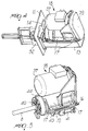
- the device 12 ( Figures 4 and 6) comprises a footing being shaped like a half-box 13 ( Figure 7) rigidly coupled to a plate 14 by means of which it is fixed with screws 15 to the side wall 11 so as to cantilever out.
- the half-box 13 has two parallel walls, on the upper edges whereof two parallel rails 16 are fixed; the sliders 17 ( Figures 4 and 5) of a movable unit 18 slide on said rails.
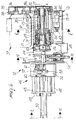
- Said unit 18 comprises a cylindrical shell 19 inside which a sleeve 22 ( Figure 10) is rotatably supported according to the axis A by means of bearings 20 and 21.
- An interspace 23 remains between the sleeve 22 and the cylindrical shell 19 and accommodates, in an intermediate position, a ring gear 24 with internal teeth which is fixed to an internal collar of the shell 19.
- the sleeve 22 encloses a cylindrical cavity 25 whose axis C is eccentric with respect to the axis A.
- a hollow shaft 28 is rotatably supported in said cavity 25 by means of bearings 26 and 27, and a gear 29 is keyed on said shaft.
- the keying of the gear 29 on the shaft 28 is rotationally provided by means of a key 30 and is axially provided by means of spacer bushes 31 and 32 which lie between the gear 29 and the bearings 26 and 27.
- the gear 29 meshes with the gear 24 by means of an opening 33 which covers an arc of the sleeve 22.
- the hollow shaft 28 has an end, the right one in Figure 6, which protrudes out of the sleeve, and a pulley 34 is rotationally rigidly coupled thereon.
- a belt 35 is wound around the pulley 34 and is closed in a loop around a second pulley 36 keyed on the output shaft of a motor 37 mounted on a flange 38 which rises from the cylindrical shell 19.
- the transmission composed of the belt 35 and the pulleys 34, 36 is covered by a housing 39 which is fixed to the flange 38 by means of screws 39a.
- the hollow shaft 28, at the end that lies opposite the pulley 34, is preset for the coupling of a tool 40 which, in the illustrated example, is of the type suitable to perform the external machining of a bar B which is aligned with the axis A, transferred from the magazine 2 and is arranged in front of it.
- a tool 40 which, in the illustrated example, is of the type suitable to perform the external machining of a bar B which is aligned with the axis A, transferred from the magazine 2 and is arranged in front of it.
- the bar B is machined by combining the axial movement of the unit 18 with the rotation of the tool 40.
- Axial movement is actuated by a fluid-actuated jack 41 accommodated in the half-box 13 below the unit 18 and in which the cylinder is rigidly coupled to the head wall 42 of the half-box and the stem acts on a lug 43 which protrudes downwards from the shell 19.
- the unit 18 is moved axially along the rails 16.
- the rotation imparted to the hollow shaft 28 by the motor 37 determines, due to the eccentricity of the axis C of the shaft 28 with respect to the axis A of the sleeve 19 and due to the meshing of the gears 24, 29, an orbital movement of the hollow shaft 28 and therefore of the tool 40 and the gradual removal of an outer layer S of the end of the bar B.
- the chips formed during this machining are collected by a housing 44 which surrounds the tool 40, leaving a front opening for the bar B, and are collected in a container 45 fixed below the half-box 13.
- the described device 12 In order to position the bar B in front of the tool 40, the described device 12 provides for a translatory assembly 46, which picks up the bar B from the magazine 2 and moves it toward the tool by a preset extent, and a locking assembly 47 which keeps the bar locked during machining.
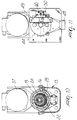
- the translatory assembly 46 comprises ( Figures 8 and 9) two rods 48 which are parallel to the axis A and are fixed to the plate 14 so as to cantilever out.
- the rods 48 are connected one another by a cross-member 49 on which an actuator 50 is fitted; said actuator is constituted by a fluid-actuated jack whose stem 51 is connected to a carriage 52 which can slide on the rods 48.
- Two pivots 53 and 54 are pivoted in the carriage 52 and are perpendicular to the rods; on the opposite sides of the carriage, said pivots support respective arms 55, 56 and 57, 58.
- the arms 57, 58 are articulately connected to a block 59 which is fixed to the stem 60 of a jack 61 whose axis is parallel to the rods 48.
- the jack 61 is coupled, by means of a flange, to an L-shaped element 62 being fixed laterally to the carriage 52.
- the arms 55, 56 have, at their ends, jaws 63, 64 which are constituted by cylinders which are parallel to the pivots 53, 54.
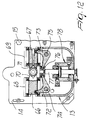
- the bar B After passing through the plate 14, the bar B is gripped by the assembly 47, which as shown more clearly in Figure 12 comprises two sliders 66 and 67 which can slide in respective guides 68 and 69 rigidly coupled to the plate 14 and have mutually opposite jaws 70 and 71.
- the sliders 66 and 67 are moved in opposite directions one another by means of two levers 72 and 73 which are pivoted in a rocker-like manner on pivots 74 and 75 rigidly coupled to the plate 14.
- the levers 72 and 73 have an arm which is pivoted in the sliders 66 and 67 and another arm which is pivoted in an element 76 rigidly coupled to the end of the stem 77 of a double-acting fluid-actuated jack 78 which is fitted inside the half-box 13, between the plate 14 and the housing 44.
- the operation of the described bar feeder is evident from the above description and can be summarized as follows.
- the last bar i.e. the bar B1
- the jaws 63 and 64 of the translatory assembly 46 is spaced from the others and aligned with the jaws 63 and 64 of the translatory assembly 46.
- a first step the carriage 52 is actuated into a position in which the jaws 63 and 64, when the jack 61 is activated, grip the end of the bar B1 and then, when the jack 50 is activated, transfer it in front of the tool 40.
- the jack 78 is activated and locks the bar by actuating the jaws 70 and 71.
- the subsequent step provides for the advancement of the unit 18 by means of the jack 14 and the facing of the bar by means of the tool 40. Once said machining has ended, the return of the unit 18 is actuated and the jaws 70 and 71 are released, so as to allow to reposition the bar in the magazine.
- Figures 13 and 14 illustrate a facing device in which the components that are identical or equivalent to those of the device of Figures 4-12 are designated by the same reference numerals increased by 100.
- the assemblies 146 and 147 are fully identical.
- the differences consist in that the advancement of the tool 140 is achieved not by moving the unit 118, as in the preceding example, but by rotatably supporting the shaft 128 coaxially in the sleeve 122 and guiding said sleeve axially into the shell 119 without turning about its own axis.
- the sleeve 122 is externally provided with an axial groove 79 which is engaged by a pin 80 protruding inside the shell 119.
- a collar 81 which slides sealingly in a seat 82 provided in the internal wall of the shell 119.
- the collar 81 constitutes, in practice, a piston which divides the seat 82 into two chambers which are connected to the delivery and the return of a pressurized liquid, so as to determine the advancement of the sleeve 122 and of the tool 140 toward the bar B in order to perform facing and then retract the tool once facing has been completed.
- the locking assembly 147 is arranged on the opposite side of the plate 114 so that its jaws can move at right angles to the surface 4 in order to allow, in the open condition, the ends of the bars to pass between them and allow, in the closed condition, the bar to be machined to stop in alignment with the axis A. Once the bar has been locked, the unit 118 can be made to advance in order to perform facing.
- the device of Figure 15 is particularly suitable for performing facings consisting of a simple axial hole of the bar, which can be provided by means of a drilling tool 83.
- Still another variation of the invention uses on the surface 4 of the magazine 2 a toothed spacer 84 which is suitable to maintain mutual separation of the bars B arranged on the surface 4, in order to allow the arrangement of the translatory assembly 46 and the machining of the bar that lies upstream of the lowermost bar.
Landscapes
- Engineering & Computer Science (AREA)
- Mechanical Engineering (AREA)
- Turning (AREA)
- Replacement Of Web Rolls (AREA)
- Paper (AREA)
- Manufacture, Treatment Of Glass Fibers (AREA)
- Accessories And Tools For Shearing Machines (AREA)
Applications Claiming Priority (2)
| Application Number | Priority Date | Filing Date | Title |
|---|---|---|---|
| IT1999BO000687A IT1311432B1 (it) | 1999-12-16 | 1999-12-16 | Caricatore di barre dotato di un dispositivo di intestatura dellebarre. |
| ITBO990687 | 1999-12-16 |
Publications (3)
| Publication Number | Publication Date |
|---|---|
| EP1108488A2 true EP1108488A2 (de) | 2001-06-20 |
| EP1108488A3 EP1108488A3 (de) | 2002-07-24 |
| EP1108488B1 EP1108488B1 (de) | 2005-08-10 |
Family
ID=11344416
Family Applications (1)
| Application Number | Title | Priority Date | Filing Date |
|---|---|---|---|
| EP00126527A Expired - Lifetime EP1108488B1 (de) | 1999-12-16 | 2000-12-11 | Stangenführung mit Plandrehvorrichtung der Stangen |
Country Status (7)
| Country | Link |
|---|---|
| US (1) | US6758118B2 (de) |
| EP (1) | EP1108488B1 (de) |
| JP (1) | JP4712186B2 (de) |
| AT (1) | ATE301522T1 (de) |
| DE (1) | DE60021841T9 (de) |
| ES (1) | ES2242575T3 (de) |
| IT (1) | IT1311432B1 (de) |
Cited By (1)
| Publication number | Priority date | Publication date | Assignee | Title |
|---|---|---|---|---|
| WO2016087574A3 (de) * | 2014-12-05 | 2016-07-28 | Index-Werke Gmbh & Co. Kg Hahn & Tessky | Stangenzufuhreinrichtung |
Families Citing this family (5)
| Publication number | Priority date | Publication date | Assignee | Title |
|---|---|---|---|---|
| US20070084318A1 (en) * | 2005-09-13 | 2007-04-19 | Tolga Unver | Bar Feeding Apparatus and Method |
| US20080041200A1 (en) * | 2006-02-22 | 2008-02-21 | Kneebusch William C | Method and apparatus for feeding bars into a cutting lathe |
| US8051755B2 (en) * | 2006-10-24 | 2011-11-08 | Alps Tool Co., Ltd. | Bar feeder, feed rod vibration prevention support of material feeder and vibration stopper of material feeder |
| ATE448037T1 (de) * | 2007-07-06 | 2009-11-15 | Lns Sa | Vorrichtung zum sequentiellen zuführen von stangen zu einer bearbeitungsmaschine |
| JP5904683B2 (ja) * | 2012-09-24 | 2016-04-20 | 育良精機株式会社 | 棒材供給機 |
Family Cites Families (6)
| Publication number | Priority date | Publication date | Assignee | Title |
|---|---|---|---|---|
| GB691087A (en) | 1951-03-12 | 1953-05-06 | H W Ward & Co Ltd | Stock-bar feed mechanism for lathes |
| US3774753A (en) | 1972-03-27 | 1973-11-27 | O Jones | Bundle feed device |
| JPS6195801A (ja) * | 1984-10-12 | 1986-05-14 | Babcock Hitachi Kk | 開先加工工具 |
| JPH0340482Y2 (de) * | 1985-12-19 | 1991-08-26 | ||
| IT1235591B (it) * | 1989-09-08 | 1992-09-11 | Iemca Spa | Dispositivo di azionamento dello spingibarra per alimentatori di barreapplicati a macchine utensili |
| JPH05131301A (ja) * | 1991-11-07 | 1993-05-28 | Kiwa Giken Kk | バー材加工旋盤 |
-
1999
- 1999-12-16 IT IT1999BO000687A patent/IT1311432B1/it active
-
2000
- 2000-12-08 US US09/731,810 patent/US6758118B2/en not_active Expired - Lifetime
- 2000-12-11 ES ES00126527T patent/ES2242575T3/es not_active Expired - Lifetime
- 2000-12-11 EP EP00126527A patent/EP1108488B1/de not_active Expired - Lifetime
- 2000-12-11 AT AT00126527T patent/ATE301522T1/de active
- 2000-12-11 DE DE60021841T patent/DE60021841T9/de active Active
- 2000-12-18 JP JP2000384093A patent/JP4712186B2/ja not_active Expired - Lifetime
Cited By (1)
| Publication number | Priority date | Publication date | Assignee | Title |
|---|---|---|---|---|
| WO2016087574A3 (de) * | 2014-12-05 | 2016-07-28 | Index-Werke Gmbh & Co. Kg Hahn & Tessky | Stangenzufuhreinrichtung |
Also Published As
| Publication number | Publication date |
|---|---|
| US20010003934A1 (en) | 2001-06-21 |
| JP2001198705A (ja) | 2001-07-24 |
| ES2242575T3 (es) | 2005-11-16 |
| ITBO990687A0 (it) | 1999-12-16 |
| IT1311432B1 (it) | 2002-03-12 |
| ATE301522T1 (de) | 2005-08-15 |
| DE60021841D1 (de) | 2005-09-15 |
| EP1108488A3 (de) | 2002-07-24 |
| ITBO990687A1 (it) | 2001-06-16 |
| DE60021841T9 (de) | 2006-07-20 |
| DE60021841T2 (de) | 2006-04-13 |
| JP4712186B2 (ja) | 2011-06-29 |
| EP1108488B1 (de) | 2005-08-10 |
| US6758118B2 (en) | 2004-07-06 |
Similar Documents
| Publication | Publication Date | Title |
|---|---|---|
| EP0700742A1 (de) | Automatische Werkstoffstangen-Zuführeinrichtung für Werkzeugmaschinen, insbesondere Drehautomaten. | |
| EP1225026B1 (de) | Verbesserungen an Spritzgiessmaschinen | |
| EP1108488B1 (de) | Stangenführung mit Plandrehvorrichtung der Stangen | |
| DE2536671A1 (de) | Werkzeugmaschine mit einer spindel und einer werkzeugwechseleinrichtung | |
| US4557166A (en) | Automatic multiple workpiece turning machine | |
| DE2537473C3 (de) | Vorschubeinrichtung an einem Stangenlademagazin | |
| WO2013159630A1 (zh) | 自动不停机装夹工件的深孔抬刀车床 | |
| DE1477419A1 (de) | Mehrspindel-Drehautomat | |
| US5562381A (en) | Bar loaders for automatic lathes | |
| JPH0141442B2 (de) | ||
| EP4112224B1 (de) | Greifwagenanordnung, bearbeitungssystem und verfahren zum bewegen eines werkstücks in bezug auf eine bearbeitungsstation | |
| US4105361A (en) | Machine tool having quill control means | |
| IT8648281A1 (it) | Procedimento per il bloccaggio rapido e di precisione di pezzi di lavoro a simmetria di rotazione e dispositivo per la realizzazione del procedimento | |
| WO2012130444A1 (de) | Buchsenausrichtvorrichtung für stangenlademagazine und verfahren | |
| SU1710727A1 (ru) | Бурильна машина | |
| US3435963A (en) | Stock feed mechanism | |
| KR20110078330A (ko) | 선반의 공작물 자동 수취장치 | |
| SU872048A1 (ru) | Патрон дл обработки наружных и внутренних цилиндрических поверхностей, смещенных относительно оси детали | |
| JPH0742561Y2 (ja) | 棒材供給機 | |
| JPH0749162B2 (ja) | 棒材供給機の送り込みバー | |
| SU1355360A1 (ru) | Токарный автомат | |
| SU1256869A1 (ru) | Расточна головка дл многопроходной обработки внутренних поверхностей | |
| IT202100015848A1 (it) | Caricatore di barre per l’alimentazione di macchine utensili con ciclo di cambio barra ottimizzato | |
| SU1763098A1 (ru) | Револьверна головка | |
| KR890006215Y1 (ko) | 중공관 내경용 라이닝 머시인의 중공관 회전력 차단장치 |
Legal Events
| Date | Code | Title | Description |
|---|---|---|---|
| PUAI | Public reference made under article 153(3) epc to a published international application that has entered the european phase |
Free format text: ORIGINAL CODE: 0009012 |
|
| AK | Designated contracting states |
Kind code of ref document: A2 Designated state(s): AT BE CH CY DE DK ES FI FR GB GR IE IT LI LU MC NL PT SE TR |
|
| AX | Request for extension of the european patent |
Free format text: AL;LT;LV;MK;RO;SI |
|
| PUAL | Search report despatched |
Free format text: ORIGINAL CODE: 0009013 |
|
| AK | Designated contracting states |
Kind code of ref document: A3 Designated state(s): AT BE CH CY DE DK ES FI FR GB GR IE IT LI LU MC NL PT SE TR |
|
| AX | Request for extension of the european patent |
Free format text: AL;LT;LV;MK;RO;SI |
|
| 17P | Request for examination filed |
Effective date: 20030114 |
|
| AKX | Designation fees paid |
Designated state(s): AT BE CH CY DE DK ES FI FR GB GR IE IT LI LU MC NL PT SE TR |
|
| GRAP | Despatch of communication of intention to grant a patent |
Free format text: ORIGINAL CODE: EPIDOSNIGR1 |
|
| GRAS | Grant fee paid |
Free format text: ORIGINAL CODE: EPIDOSNIGR3 |
|
| GRAA | (expected) grant |
Free format text: ORIGINAL CODE: 0009210 |
|
| AK | Designated contracting states |
Kind code of ref document: B1 Designated state(s): AT BE CH CY DE DK ES FI FR GB GR IE IT LI LU MC NL PT SE TR |
|
| PG25 | Lapsed in a contracting state [announced via postgrant information from national office to epo] |
Ref country code: TR Free format text: LAPSE BECAUSE OF FAILURE TO SUBMIT A TRANSLATION OF THE DESCRIPTION OR TO PAY THE FEE WITHIN THE PRESCRIBED TIME-LIMIT Effective date: 20050810 Ref country code: NL Free format text: LAPSE BECAUSE OF FAILURE TO SUBMIT A TRANSLATION OF THE DESCRIPTION OR TO PAY THE FEE WITHIN THE PRESCRIBED TIME-LIMIT Effective date: 20050810 Ref country code: FI Free format text: LAPSE BECAUSE OF FAILURE TO SUBMIT A TRANSLATION OF THE DESCRIPTION OR TO PAY THE FEE WITHIN THE PRESCRIBED TIME-LIMIT Effective date: 20050810 Ref country code: BE Free format text: LAPSE BECAUSE OF FAILURE TO SUBMIT A TRANSLATION OF THE DESCRIPTION OR TO PAY THE FEE WITHIN THE PRESCRIBED TIME-LIMIT Effective date: 20050810 |
|
| REG | Reference to a national code |
Ref country code: GB Ref legal event code: FG4D |
|
| REG | Reference to a national code |
Ref country code: CH Ref legal event code: EP |
|
| REG | Reference to a national code |
Ref country code: IE Ref legal event code: FG4D |
|
| REF | Corresponds to: |
Ref document number: 60021841 Country of ref document: DE Date of ref document: 20050915 Kind code of ref document: P |
|
| REG | Reference to a national code |
Ref country code: CH Ref legal event code: NV Representative=s name: MARK-PAT MODIANO S.A. |
|
| PG25 | Lapsed in a contracting state [announced via postgrant information from national office to epo] |
Ref country code: DK Free format text: LAPSE BECAUSE OF FAILURE TO SUBMIT A TRANSLATION OF THE DESCRIPTION OR TO PAY THE FEE WITHIN THE PRESCRIBED TIME-LIMIT Effective date: 20051110 Ref country code: GR Free format text: LAPSE BECAUSE OF FAILURE TO SUBMIT A TRANSLATION OF THE DESCRIPTION OR TO PAY THE FEE WITHIN THE PRESCRIBED TIME-LIMIT Effective date: 20051110 Ref country code: SE Free format text: LAPSE BECAUSE OF FAILURE TO SUBMIT A TRANSLATION OF THE DESCRIPTION OR TO PAY THE FEE WITHIN THE PRESCRIBED TIME-LIMIT Effective date: 20051110 |
|
| REG | Reference to a national code |
Ref country code: ES Ref legal event code: FG2A Ref document number: 2242575 Country of ref document: ES Kind code of ref document: T3 |
|
| PG25 | Lapsed in a contracting state [announced via postgrant information from national office to epo] |
Ref country code: CY Free format text: LAPSE BECAUSE OF FAILURE TO SUBMIT A TRANSLATION OF THE DESCRIPTION OR TO PAY THE FEE WITHIN THE PRESCRIBED TIME-LIMIT Effective date: 20051211 |
|
| PG25 | Lapsed in a contracting state [announced via postgrant information from national office to epo] |
Ref country code: IE Free format text: LAPSE BECAUSE OF NON-PAYMENT OF DUE FEES Effective date: 20051212 |
|
| PG25 | Lapsed in a contracting state [announced via postgrant information from national office to epo] |
Ref country code: LU Free format text: LAPSE BECAUSE OF NON-PAYMENT OF DUE FEES Effective date: 20051231 Ref country code: MC Free format text: LAPSE BECAUSE OF NON-PAYMENT OF DUE FEES Effective date: 20051231 |
|
| PG25 | Lapsed in a contracting state [announced via postgrant information from national office to epo] |
Ref country code: PT Free format text: LAPSE BECAUSE OF FAILURE TO SUBMIT A TRANSLATION OF THE DESCRIPTION OR TO PAY THE FEE WITHIN THE PRESCRIBED TIME-LIMIT Effective date: 20060110 |
|
| NLV1 | Nl: lapsed or annulled due to failure to fulfill the requirements of art. 29p and 29m of the patents act | ||
| ET | Fr: translation filed | ||
| PLBE | No opposition filed within time limit |
Free format text: ORIGINAL CODE: 0009261 |
|
| STAA | Information on the status of an ep patent application or granted ep patent |
Free format text: STATUS: NO OPPOSITION FILED WITHIN TIME LIMIT |
|
| 26N | No opposition filed |
Effective date: 20060511 |
|
| REG | Reference to a national code |
Ref country code: IE Ref legal event code: MM4A |
|
| REG | Reference to a national code |
Ref country code: FR Ref legal event code: PLFP Year of fee payment: 16 |
|
| REG | Reference to a national code |
Ref country code: FR Ref legal event code: PLFP Year of fee payment: 17 |
|
| REG | Reference to a national code |
Ref country code: FR Ref legal event code: PLFP Year of fee payment: 18 |
|
| PGFP | Annual fee paid to national office [announced via postgrant information from national office to epo] |
Ref country code: DE Payment date: 20191128 Year of fee payment: 20 |
|
| PGFP | Annual fee paid to national office [announced via postgrant information from national office to epo] |
Ref country code: FR Payment date: 20191030 Year of fee payment: 20 Ref country code: IT Payment date: 20191213 Year of fee payment: 20 |
|
| PGFP | Annual fee paid to national office [announced via postgrant information from national office to epo] |
Ref country code: AT Payment date: 20191128 Year of fee payment: 20 |
|
| PGFP | Annual fee paid to national office [announced via postgrant information from national office to epo] |
Ref country code: GB Payment date: 20191219 Year of fee payment: 20 Ref country code: ES Payment date: 20200102 Year of fee payment: 20 |
|
| PGFP | Annual fee paid to national office [announced via postgrant information from national office to epo] |
Ref country code: CH Payment date: 20200120 Year of fee payment: 20 |
|
| REG | Reference to a national code |
Ref country code: DE Ref legal event code: R071 Ref document number: 60021841 Country of ref document: DE |
|
| REG | Reference to a national code |
Ref country code: CH Ref legal event code: PL |
|
| REG | Reference to a national code |
Ref country code: GB Ref legal event code: PE20 Expiry date: 20201210 |
|
| PG25 | Lapsed in a contracting state [announced via postgrant information from national office to epo] |
Ref country code: GB Free format text: LAPSE BECAUSE OF EXPIRATION OF PROTECTION Effective date: 20201210 |
|
| REG | Reference to a national code |
Ref country code: AT Ref legal event code: MK07 Ref document number: 301522 Country of ref document: AT Kind code of ref document: T Effective date: 20201211 |
|
| REG | Reference to a national code |
Ref country code: ES Ref legal event code: FD2A Effective date: 20210730 |
|
| PG25 | Lapsed in a contracting state [announced via postgrant information from national office to epo] |
Ref country code: ES Free format text: LAPSE BECAUSE OF EXPIRATION OF PROTECTION Effective date: 20201212 |