EP1110802A2 - Véhicule électrique - Google Patents
Véhicule électrique Download PDFInfo
- Publication number
- EP1110802A2 EP1110802A2 EP01103605A EP01103605A EP1110802A2 EP 1110802 A2 EP1110802 A2 EP 1110802A2 EP 01103605 A EP01103605 A EP 01103605A EP 01103605 A EP01103605 A EP 01103605A EP 1110802 A2 EP1110802 A2 EP 1110802A2
- Authority
- EP
- European Patent Office
- Prior art keywords
- electric motor
- motor vehicle
- battery
- inverter device
- semiconductor
- Prior art date
- Legal status (The legal status is an assumption and is not a legal conclusion. Google has not performed a legal analysis and makes no representation as to the accuracy of the status listed.)
- Withdrawn
Links
Images





Classifications
-
- B—PERFORMING OPERATIONS; TRANSPORTING
- B60—VEHICLES IN GENERAL
- B60L—PROPULSION OF ELECTRICALLY-PROPELLED VEHICLES; SUPPLYING ELECTRIC POWER FOR AUXILIARY EQUIPMENT OF ELECTRICALLY-PROPELLED VEHICLES; ELECTRODYNAMIC BRAKE SYSTEMS FOR VEHICLES IN GENERAL; MAGNETIC SUSPENSION OR LEVITATION FOR VEHICLES; MONITORING OPERATING VARIABLES OF ELECTRICALLY-PROPELLED VEHICLES; ELECTRIC SAFETY DEVICES FOR ELECTRICALLY-PROPELLED VEHICLES
- B60L15/00—Methods, circuits, or devices for controlling the traction-motor speed of electrically-propelled vehicles
- B60L15/20—Methods, circuits, or devices for controlling the traction-motor speed of electrically-propelled vehicles for control of the vehicle or its driving motor to achieve a desired performance, e.g. speed, torque, programmed variation of speed
-
- B—PERFORMING OPERATIONS; TRANSPORTING
- B62—LAND VEHICLES FOR TRAVELLING OTHERWISE THAN ON RAILS
- B62M—RIDER PROPULSION OF WHEELED VEHICLES OR SLEDGES; POWERED PROPULSION OF SLEDGES OR SINGLE-TRACK CYCLES; TRANSMISSIONS SPECIALLY ADAPTED FOR SUCH VEHICLES
- B62M7/00—Motorcycles characterised by position of motor or engine
-
- B—PERFORMING OPERATIONS; TRANSPORTING
- B60—VEHICLES IN GENERAL
- B60K—ARRANGEMENT OR MOUNTING OF PROPULSION UNITS OR OF TRANSMISSIONS IN VEHICLES; ARRANGEMENT OR MOUNTING OF PLURAL DIVERSE PRIME-MOVERS IN VEHICLES; AUXILIARY DRIVES FOR VEHICLES; INSTRUMENTATION OR DASHBOARDS FOR VEHICLES; ARRANGEMENTS IN CONNECTION WITH COOLING, AIR INTAKE, GAS EXHAUST OR FUEL SUPPLY OF PROPULSION UNITS IN VEHICLES
- B60K7/00—Disposition of motor in, or adjacent to, traction wheel
- B60K7/0007—Disposition of motor in, or adjacent to, traction wheel the motor being electric
-
- B—PERFORMING OPERATIONS; TRANSPORTING
- B60—VEHICLES IN GENERAL
- B60L—PROPULSION OF ELECTRICALLY-PROPELLED VEHICLES; SUPPLYING ELECTRIC POWER FOR AUXILIARY EQUIPMENT OF ELECTRICALLY-PROPELLED VEHICLES; ELECTRODYNAMIC BRAKE SYSTEMS FOR VEHICLES IN GENERAL; MAGNETIC SUSPENSION OR LEVITATION FOR VEHICLES; MONITORING OPERATING VARIABLES OF ELECTRICALLY-PROPELLED VEHICLES; ELECTRIC SAFETY DEVICES FOR ELECTRICALLY-PROPELLED VEHICLES
- B60L3/00—Electric devices on electrically-propelled vehicles for safety purposes; Monitoring operating variables, e.g. speed, deceleration or energy consumption
-
- B—PERFORMING OPERATIONS; TRANSPORTING
- B60—VEHICLES IN GENERAL
- B60L—PROPULSION OF ELECTRICALLY-PROPELLED VEHICLES; SUPPLYING ELECTRIC POWER FOR AUXILIARY EQUIPMENT OF ELECTRICALLY-PROPELLED VEHICLES; ELECTRODYNAMIC BRAKE SYSTEMS FOR VEHICLES IN GENERAL; MAGNETIC SUSPENSION OR LEVITATION FOR VEHICLES; MONITORING OPERATING VARIABLES OF ELECTRICALLY-PROPELLED VEHICLES; ELECTRIC SAFETY DEVICES FOR ELECTRICALLY-PROPELLED VEHICLES
- B60L3/00—Electric devices on electrically-propelled vehicles for safety purposes; Monitoring operating variables, e.g. speed, deceleration or energy consumption
- B60L3/0023—Detecting, eliminating, remedying or compensating for drive train abnormalities, e.g. failures within the drive train
-
- B—PERFORMING OPERATIONS; TRANSPORTING
- B60—VEHICLES IN GENERAL
- B60L—PROPULSION OF ELECTRICALLY-PROPELLED VEHICLES; SUPPLYING ELECTRIC POWER FOR AUXILIARY EQUIPMENT OF ELECTRICALLY-PROPELLED VEHICLES; ELECTRODYNAMIC BRAKE SYSTEMS FOR VEHICLES IN GENERAL; MAGNETIC SUSPENSION OR LEVITATION FOR VEHICLES; MONITORING OPERATING VARIABLES OF ELECTRICALLY-PROPELLED VEHICLES; ELECTRIC SAFETY DEVICES FOR ELECTRICALLY-PROPELLED VEHICLES
- B60L3/00—Electric devices on electrically-propelled vehicles for safety purposes; Monitoring operating variables, e.g. speed, deceleration or energy consumption
- B60L3/0023—Detecting, eliminating, remedying or compensating for drive train abnormalities, e.g. failures within the drive train
- B60L3/003—Detecting, eliminating, remedying or compensating for drive train abnormalities, e.g. failures within the drive train relating to inverters
-
- B—PERFORMING OPERATIONS; TRANSPORTING
- B60—VEHICLES IN GENERAL
- B60L—PROPULSION OF ELECTRICALLY-PROPELLED VEHICLES; SUPPLYING ELECTRIC POWER FOR AUXILIARY EQUIPMENT OF ELECTRICALLY-PROPELLED VEHICLES; ELECTRODYNAMIC BRAKE SYSTEMS FOR VEHICLES IN GENERAL; MAGNETIC SUSPENSION OR LEVITATION FOR VEHICLES; MONITORING OPERATING VARIABLES OF ELECTRICALLY-PROPELLED VEHICLES; ELECTRIC SAFETY DEVICES FOR ELECTRICALLY-PROPELLED VEHICLES
- B60L3/00—Electric devices on electrically-propelled vehicles for safety purposes; Monitoring operating variables, e.g. speed, deceleration or energy consumption
- B60L3/0023—Detecting, eliminating, remedying or compensating for drive train abnormalities, e.g. failures within the drive train
- B60L3/0046—Detecting, eliminating, remedying or compensating for drive train abnormalities, e.g. failures within the drive train relating to electric energy storage systems, e.g. batteries or capacitors
-
- B—PERFORMING OPERATIONS; TRANSPORTING
- B60—VEHICLES IN GENERAL
- B60L—PROPULSION OF ELECTRICALLY-PROPELLED VEHICLES; SUPPLYING ELECTRIC POWER FOR AUXILIARY EQUIPMENT OF ELECTRICALLY-PROPELLED VEHICLES; ELECTRODYNAMIC BRAKE SYSTEMS FOR VEHICLES IN GENERAL; MAGNETIC SUSPENSION OR LEVITATION FOR VEHICLES; MONITORING OPERATING VARIABLES OF ELECTRICALLY-PROPELLED VEHICLES; ELECTRIC SAFETY DEVICES FOR ELECTRICALLY-PROPELLED VEHICLES
- B60L3/00—Electric devices on electrically-propelled vehicles for safety purposes; Monitoring operating variables, e.g. speed, deceleration or energy consumption
- B60L3/06—Limiting the traction current under mechanical overload conditions
-
- B—PERFORMING OPERATIONS; TRANSPORTING
- B60—VEHICLES IN GENERAL
- B60L—PROPULSION OF ELECTRICALLY-PROPELLED VEHICLES; SUPPLYING ELECTRIC POWER FOR AUXILIARY EQUIPMENT OF ELECTRICALLY-PROPELLED VEHICLES; ELECTRODYNAMIC BRAKE SYSTEMS FOR VEHICLES IN GENERAL; MAGNETIC SUSPENSION OR LEVITATION FOR VEHICLES; MONITORING OPERATING VARIABLES OF ELECTRICALLY-PROPELLED VEHICLES; ELECTRIC SAFETY DEVICES FOR ELECTRICALLY-PROPELLED VEHICLES
- B60L50/00—Electric propulsion with power supplied within the vehicle
- B60L50/50—Electric propulsion with power supplied within the vehicle using propulsion power supplied by batteries or fuel cells
- B60L50/60—Electric propulsion with power supplied within the vehicle using propulsion power supplied by batteries or fuel cells using power supplied by batteries
-
- B—PERFORMING OPERATIONS; TRANSPORTING
- B60—VEHICLES IN GENERAL
- B60L—PROPULSION OF ELECTRICALLY-PROPELLED VEHICLES; SUPPLYING ELECTRIC POWER FOR AUXILIARY EQUIPMENT OF ELECTRICALLY-PROPELLED VEHICLES; ELECTRODYNAMIC BRAKE SYSTEMS FOR VEHICLES IN GENERAL; MAGNETIC SUSPENSION OR LEVITATION FOR VEHICLES; MONITORING OPERATING VARIABLES OF ELECTRICALLY-PROPELLED VEHICLES; ELECTRIC SAFETY DEVICES FOR ELECTRICALLY-PROPELLED VEHICLES
- B60L58/00—Methods or circuit arrangements for monitoring or controlling batteries or fuel cells, specially adapted for electric vehicles
- B60L58/10—Methods or circuit arrangements for monitoring or controlling batteries or fuel cells, specially adapted for electric vehicles for monitoring or controlling batteries
-
- B—PERFORMING OPERATIONS; TRANSPORTING
- B62—LAND VEHICLES FOR TRAVELLING OTHERWISE THAN ON RAILS
- B62M—RIDER PROPULSION OF WHEELED VEHICLES OR SLEDGES; POWERED PROPULSION OF SLEDGES OR SINGLE-TRACK CYCLES; TRANSMISSIONS SPECIALLY ADAPTED FOR SUCH VEHICLES
- B62M7/00—Motorcycles characterised by position of motor or engine
- B62M7/12—Motorcycles characterised by position of motor or engine with the engine beside or within the driven wheel
-
- H—ELECTRICITY
- H02—GENERATION; CONVERSION OR DISTRIBUTION OF ELECTRIC POWER
- H02K—DYNAMO-ELECTRIC MACHINES
- H02K1/00—Details of the magnetic circuit
- H02K1/06—Details of the magnetic circuit characterised by the shape, form or construction
- H02K1/12—Stationary parts of the magnetic circuit
- H02K1/18—Means for mounting or fastening magnetic stationary parts on to, or to, the stator structures
- H02K1/185—Means for mounting or fastening magnetic stationary parts on to, or to, the stator structures to outer stators
-
- H—ELECTRICITY
- H02—GENERATION; CONVERSION OR DISTRIBUTION OF ELECTRIC POWER
- H02K—DYNAMO-ELECTRIC MACHINES
- H02K1/00—Details of the magnetic circuit
- H02K1/06—Details of the magnetic circuit characterised by the shape, form or construction
- H02K1/22—Rotating parts of the magnetic circuit
- H02K1/27—Rotor cores with permanent magnets
- H02K1/2706—Inner rotors
- H02K1/272—Inner rotors the magnetisation axis of the magnets being perpendicular to the rotor axis
- H02K1/274—Inner rotors the magnetisation axis of the magnets being perpendicular to the rotor axis the rotor consisting of two or more circumferentially positioned magnets
- H02K1/2753—Inner rotors the magnetisation axis of the magnets being perpendicular to the rotor axis the rotor consisting of two or more circumferentially positioned magnets the rotor consisting of magnets or groups of magnets arranged with alternating polarity
- H02K1/276—Magnets embedded in the magnetic core, e.g. interior permanent magnets [IPM]
-
- H—ELECTRICITY
- H02—GENERATION; CONVERSION OR DISTRIBUTION OF ELECTRIC POWER
- H02K—DYNAMO-ELECTRIC MACHINES
- H02K29/00—Motors or generators having non-mechanical commutating devices, e.g. discharge tubes or semiconductor devices
- H02K29/06—Motors or generators having non-mechanical commutating devices, e.g. discharge tubes or semiconductor devices with position sensing devices
- H02K29/08—Motors or generators having non-mechanical commutating devices, e.g. discharge tubes or semiconductor devices with position sensing devices using magnetic effect devices, e.g. Hall-plates, magneto-resistors
-
- B—PERFORMING OPERATIONS; TRANSPORTING
- B60—VEHICLES IN GENERAL
- B60G—VEHICLE SUSPENSION ARRANGEMENTS
- B60G2204/00—Indexing codes related to suspensions per se or to auxiliary parts
- B60G2204/10—Mounting of suspension elements
- B60G2204/30—In-wheel mountings
-
- B—PERFORMING OPERATIONS; TRANSPORTING
- B60—VEHICLES IN GENERAL
- B60K—ARRANGEMENT OR MOUNTING OF PROPULSION UNITS OR OF TRANSMISSIONS IN VEHICLES; ARRANGEMENT OR MOUNTING OF PLURAL DIVERSE PRIME-MOVERS IN VEHICLES; AUXILIARY DRIVES FOR VEHICLES; INSTRUMENTATION OR DASHBOARDS FOR VEHICLES; ARRANGEMENTS IN CONNECTION WITH COOLING, AIR INTAKE, GAS EXHAUST OR FUEL SUPPLY OF PROPULSION UNITS IN VEHICLES
- B60K1/00—Arrangement or mounting of electrical propulsion units
-
- B—PERFORMING OPERATIONS; TRANSPORTING
- B60—VEHICLES IN GENERAL
- B60K—ARRANGEMENT OR MOUNTING OF PROPULSION UNITS OR OF TRANSMISSIONS IN VEHICLES; ARRANGEMENT OR MOUNTING OF PLURAL DIVERSE PRIME-MOVERS IN VEHICLES; AUXILIARY DRIVES FOR VEHICLES; INSTRUMENTATION OR DASHBOARDS FOR VEHICLES; ARRANGEMENTS IN CONNECTION WITH COOLING, AIR INTAKE, GAS EXHAUST OR FUEL SUPPLY OF PROPULSION UNITS IN VEHICLES
- B60K17/00—Arrangement or mounting of transmissions in vehicles
- B60K17/04—Arrangement or mounting of transmissions in vehicles characterised by arrangement, location or kind of gearing
- B60K17/043—Transmission unit disposed in on near the vehicle wheel, or between the differential gear unit and the wheel
-
- B—PERFORMING OPERATIONS; TRANSPORTING
- B60—VEHICLES IN GENERAL
- B60K—ARRANGEMENT OR MOUNTING OF PROPULSION UNITS OR OF TRANSMISSIONS IN VEHICLES; ARRANGEMENT OR MOUNTING OF PLURAL DIVERSE PRIME-MOVERS IN VEHICLES; AUXILIARY DRIVES FOR VEHICLES; INSTRUMENTATION OR DASHBOARDS FOR VEHICLES; ARRANGEMENTS IN CONNECTION WITH COOLING, AIR INTAKE, GAS EXHAUST OR FUEL SUPPLY OF PROPULSION UNITS IN VEHICLES
- B60K7/00—Disposition of motor in, or adjacent to, traction wheel
- B60K2007/0046—Disposition of motor in, or adjacent to, traction wheel the motor moving together with the vehicle body, i.e. moving independently from the wheel axle
-
- B—PERFORMING OPERATIONS; TRANSPORTING
- B60—VEHICLES IN GENERAL
- B60K—ARRANGEMENT OR MOUNTING OF PROPULSION UNITS OR OF TRANSMISSIONS IN VEHICLES; ARRANGEMENT OR MOUNTING OF PLURAL DIVERSE PRIME-MOVERS IN VEHICLES; AUXILIARY DRIVES FOR VEHICLES; INSTRUMENTATION OR DASHBOARDS FOR VEHICLES; ARRANGEMENTS IN CONNECTION WITH COOLING, AIR INTAKE, GAS EXHAUST OR FUEL SUPPLY OF PROPULSION UNITS IN VEHICLES
- B60K7/00—Disposition of motor in, or adjacent to, traction wheel
- B60K2007/0061—Disposition of motor in, or adjacent to, traction wheel the motor axle being parallel to the wheel axle
-
- B—PERFORMING OPERATIONS; TRANSPORTING
- B60—VEHICLES IN GENERAL
- B60L—PROPULSION OF ELECTRICALLY-PROPELLED VEHICLES; SUPPLYING ELECTRIC POWER FOR AUXILIARY EQUIPMENT OF ELECTRICALLY-PROPELLED VEHICLES; ELECTRODYNAMIC BRAKE SYSTEMS FOR VEHICLES IN GENERAL; MAGNETIC SUSPENSION OR LEVITATION FOR VEHICLES; MONITORING OPERATING VARIABLES OF ELECTRICALLY-PROPELLED VEHICLES; ELECTRIC SAFETY DEVICES FOR ELECTRICALLY-PROPELLED VEHICLES
- B60L2200/00—Type of vehicles
- B60L2200/12—Bikes
-
- B—PERFORMING OPERATIONS; TRANSPORTING
- B60—VEHICLES IN GENERAL
- B60L—PROPULSION OF ELECTRICALLY-PROPELLED VEHICLES; SUPPLYING ELECTRIC POWER FOR AUXILIARY EQUIPMENT OF ELECTRICALLY-PROPELLED VEHICLES; ELECTRODYNAMIC BRAKE SYSTEMS FOR VEHICLES IN GENERAL; MAGNETIC SUSPENSION OR LEVITATION FOR VEHICLES; MONITORING OPERATING VARIABLES OF ELECTRICALLY-PROPELLED VEHICLES; ELECTRIC SAFETY DEVICES FOR ELECTRICALLY-PROPELLED VEHICLES
- B60L2220/00—Electrical machine types; Structures or applications thereof
- B60L2220/40—Electrical machine applications
- B60L2220/44—Wheel Hub motors, i.e. integrated in the wheel hub
-
- B—PERFORMING OPERATIONS; TRANSPORTING
- B60—VEHICLES IN GENERAL
- B60L—PROPULSION OF ELECTRICALLY-PROPELLED VEHICLES; SUPPLYING ELECTRIC POWER FOR AUXILIARY EQUIPMENT OF ELECTRICALLY-PROPELLED VEHICLES; ELECTRODYNAMIC BRAKE SYSTEMS FOR VEHICLES IN GENERAL; MAGNETIC SUSPENSION OR LEVITATION FOR VEHICLES; MONITORING OPERATING VARIABLES OF ELECTRICALLY-PROPELLED VEHICLES; ELECTRIC SAFETY DEVICES FOR ELECTRICALLY-PROPELLED VEHICLES
- B60L2220/00—Electrical machine types; Structures or applications thereof
- B60L2220/40—Electrical machine applications
- B60L2220/46—Wheel motors, i.e. motor connected to only one wheel
-
- B—PERFORMING OPERATIONS; TRANSPORTING
- B60—VEHICLES IN GENERAL
- B60L—PROPULSION OF ELECTRICALLY-PROPELLED VEHICLES; SUPPLYING ELECTRIC POWER FOR AUXILIARY EQUIPMENT OF ELECTRICALLY-PROPELLED VEHICLES; ELECTRODYNAMIC BRAKE SYSTEMS FOR VEHICLES IN GENERAL; MAGNETIC SUSPENSION OR LEVITATION FOR VEHICLES; MONITORING OPERATING VARIABLES OF ELECTRICALLY-PROPELLED VEHICLES; ELECTRIC SAFETY DEVICES FOR ELECTRICALLY-PROPELLED VEHICLES
- B60L2260/00—Operating Modes
- B60L2260/40—Control modes
- B60L2260/50—Control modes by future state prediction
- B60L2260/56—Temperature prediction, e.g. for pre-cooling
-
- B—PERFORMING OPERATIONS; TRANSPORTING
- B62—LAND VEHICLES FOR TRAVELLING OTHERWISE THAN ON RAILS
- B62K—CYCLES; CYCLE FRAMES; CYCLE STEERING DEVICES; RIDER-OPERATED TERMINAL CONTROLS SPECIALLY ADAPTED FOR CYCLES; CYCLE AXLE SUSPENSIONS; CYCLE SIDECARS, FORECARS, OR THE LIKE
- B62K2202/00—Motorised scooters
-
- B—PERFORMING OPERATIONS; TRANSPORTING
- B62—LAND VEHICLES FOR TRAVELLING OTHERWISE THAN ON RAILS
- B62K—CYCLES; CYCLE FRAMES; CYCLE STEERING DEVICES; RIDER-OPERATED TERMINAL CONTROLS SPECIALLY ADAPTED FOR CYCLES; CYCLE AXLE SUSPENSIONS; CYCLE SIDECARS, FORECARS, OR THE LIKE
- B62K2204/00—Adaptations for driving cycles by electric motor
-
- H—ELECTRICITY
- H02—GENERATION; CONVERSION OR DISTRIBUTION OF ELECTRIC POWER
- H02K—DYNAMO-ELECTRIC MACHINES
- H02K15/00—Processes or apparatus specially adapted for manufacturing, assembling, maintaining or repairing of dynamo-electric machines
- H02K15/04—Processes or apparatus specially adapted for manufacturing, assembling, maintaining or repairing of dynamo-electric machines of windings prior to their mounting into the machines
-
- H—ELECTRICITY
- H02—GENERATION; CONVERSION OR DISTRIBUTION OF ELECTRIC POWER
- H02K—DYNAMO-ELECTRIC MACHINES
- H02K2211/00—Specific aspects not provided for in the other groups of this subclass relating to measuring or protective devices or electric components
- H02K2211/03—Machines characterised by circuit boards, e.g. pcb
-
- H—ELECTRICITY
- H02—GENERATION; CONVERSION OR DISTRIBUTION OF ELECTRIC POWER
- H02K—DYNAMO-ELECTRIC MACHINES
- H02K5/00—Casings; Enclosures; Supports
- H02K5/04—Casings or enclosures characterised by the shape, form or construction thereof
- H02K5/10—Casings or enclosures characterised by the shape, form or construction thereof with arrangements for protection from ingress, e.g. water or fingers
-
- H—ELECTRICITY
- H02—GENERATION; CONVERSION OR DISTRIBUTION OF ELECTRIC POWER
- H02K—DYNAMO-ELECTRIC MACHINES
- H02K5/00—Casings; Enclosures; Supports
- H02K5/04—Casings or enclosures characterised by the shape, form or construction thereof
- H02K5/15—Mounting arrangements for bearing-shields or end plates
-
- H—ELECTRICITY
- H02—GENERATION; CONVERSION OR DISTRIBUTION OF ELECTRIC POWER
- H02K—DYNAMO-ELECTRIC MACHINES
- H02K5/00—Casings; Enclosures; Supports
- H02K5/04—Casings or enclosures characterised by the shape, form or construction thereof
- H02K5/22—Auxiliary parts of casings not covered by groups H02K5/06-H02K5/20, e.g. shaped to form connection boxes or terminal boxes
- H02K5/225—Terminal boxes or connection arrangements
-
- H—ELECTRICITY
- H02—GENERATION; CONVERSION OR DISTRIBUTION OF ELECTRIC POWER
- H02K—DYNAMO-ELECTRIC MACHINES
- H02K7/00—Arrangements for handling mechanical energy structurally associated with dynamo-electric machines, e.g. structural association with mechanical driving motors or auxiliary dynamo-electric machines
- H02K7/10—Structural association with clutches, brakes, gears, pulleys or mechanical starters
-
- Y—GENERAL TAGGING OF NEW TECHNOLOGICAL DEVELOPMENTS; GENERAL TAGGING OF CROSS-SECTIONAL TECHNOLOGIES SPANNING OVER SEVERAL SECTIONS OF THE IPC; TECHNICAL SUBJECTS COVERED BY FORMER USPC CROSS-REFERENCE ART COLLECTIONS [XRACs] AND DIGESTS
- Y02—TECHNOLOGIES OR APPLICATIONS FOR MITIGATION OR ADAPTATION AGAINST CLIMATE CHANGE
- Y02T—CLIMATE CHANGE MITIGATION TECHNOLOGIES RELATED TO TRANSPORTATION
- Y02T10/00—Road transport of goods or passengers
- Y02T10/60—Other road transportation technologies with climate change mitigation effect
- Y02T10/64—Electric machine technologies in electromobility
-
- Y—GENERAL TAGGING OF NEW TECHNOLOGICAL DEVELOPMENTS; GENERAL TAGGING OF CROSS-SECTIONAL TECHNOLOGIES SPANNING OVER SEVERAL SECTIONS OF THE IPC; TECHNICAL SUBJECTS COVERED BY FORMER USPC CROSS-REFERENCE ART COLLECTIONS [XRACs] AND DIGESTS
- Y02—TECHNOLOGIES OR APPLICATIONS FOR MITIGATION OR ADAPTATION AGAINST CLIMATE CHANGE
- Y02T—CLIMATE CHANGE MITIGATION TECHNOLOGIES RELATED TO TRANSPORTATION
- Y02T10/00—Road transport of goods or passengers
- Y02T10/60—Other road transportation technologies with climate change mitigation effect
- Y02T10/70—Energy storage systems for electromobility, e.g. batteries
-
- Y—GENERAL TAGGING OF NEW TECHNOLOGICAL DEVELOPMENTS; GENERAL TAGGING OF CROSS-SECTIONAL TECHNOLOGIES SPANNING OVER SEVERAL SECTIONS OF THE IPC; TECHNICAL SUBJECTS COVERED BY FORMER USPC CROSS-REFERENCE ART COLLECTIONS [XRACs] AND DIGESTS
- Y02—TECHNOLOGIES OR APPLICATIONS FOR MITIGATION OR ADAPTATION AGAINST CLIMATE CHANGE
- Y02T—CLIMATE CHANGE MITIGATION TECHNOLOGIES RELATED TO TRANSPORTATION
- Y02T10/00—Road transport of goods or passengers
- Y02T10/60—Other road transportation technologies with climate change mitigation effect
- Y02T10/72—Electric energy management in electromobility
Definitions
- This invention relates to an electric motor vehicle using a motor as a drive motive power, and particularly to an electric motor vehicle which is preferably applied to two wheelers and three wheelers such as motorcycles and scooters.
- Known electric motor vehicles are provided as their drive system with a battery, a motor, and a controller for controlling the speed of the motor, and a wheel is rotated by a drive transmission mechanism like conventional automobiles, or a wheel is rotated by a motor disposed an it without necessitating such a drive transmission mechanism like conventional automobiles. And, in developing an electric motor vehicle, the improvement of the performance of an onboard battery is an issue to be solved and it will not be long before it is solved.
- the electric motor vehicle is also demanded to have its safety improved together with the improvement of its performance.
- a mere replacement of the drive motive power of a conventional gasoline automobile by a motor can not sufficiently provide the safety of the electric motor vehicle.
- the electric motor vehicle uses electricity for a drive source, and the power is a motor which rotates at a high speed as compared with an engine. Therefore, a trouble of the electric system or a failure of the motor may suddenly stop a running vehicle or suddenly start a vehicle which was out of action.
- a driver or a mechanic may suffer from an electric shock, be caught by the drive unit in the vicinity of the motor, or break the motor or the controller when servicing.
- the inventors involved in the development of an electric motor vehicle propose the following points to prevent accidents or failures from occurring and to assure safety.
- First point for safety To avoid a travel motion trouble of the electric motor vehicle which may suddenly occur when travelling, for example, a sudden stop of the electric motor vehicle.
- Second point for safety To prevent a sudden start of the electronic motor vehicle which may happen suddenly.
- the above first to fourth points for safety are not sufficient if any of them is alternatively disposed an the electric motor vehicle but all of them shall be preferably disposed on the electric motor vehicle.
- the above first and second aspects relate to the drive system of the electric motor vehicle and also to at least any of the above first to fourth points for safety.
- the above first and second aspects of this application are closely related to one another for securing safety. They will be described hereinafter in detail to clarify the contents of this application which aims to obtain an electric motor vehicle having high safety.
- a known means for preventing a short circuit between battery terminals when a key switch is off is as follows.
- Fig. 13 shows a conventional drive circuit diagram of a motor controller.
- An example using a MOSFET as a semiconductor switch and a DC brushless motor as a motor will be described hereinbelow.
- reference numeral 121 stands for a battery.
- An inverter device 122 consists of a semiconductor switch 127 (127a to 127f) and a diode 128 (128a to 128f), and the semiconductor switch 127 is turned an or off according to an electrifying signal 126 from a control circuit 125 to apply a current to a motor 131.
- the semiconductor switch to be electrified is selected according to a rotor position signal 133 from an encoder 132 for detecting the rotor position and the opening of an accelerator 134.
- a power source 123 lowers the voltage of the battery 121 to an appropriate stabilized voltage. But, the power source 123 may be one independent from the battery.
- Reference numeral 124 represents a key switch.
- the semiconductor switch 127 is turned on or off according to four power sources 129 (129a to 129f) having the output insulated respectively and a control circuit 130 (130a to 130f) disposed for each element.
- the control circuit 130 receives power from the Power sources 129 and applies a positive or negative voltage to the control terminal of the semiconductor switch 127 according to the electrically insulated electrifying signal 126. When the applied voltage is positive, the semiconductor switch 127 is turned on, and when negative, it is turned off.
- Fig. 15 is a circuit diagram specifically showing a part of the control circuit 130 and a control circuit 125.
- the electrifying signal 126 is sent as an optical signal to the control circuit 130 using a photo-coupler 226.
- the electrifying signal 126 is outputted for a period that a transistor 229 is on, and at this time, a transistor 227 is turned on and a transistor 228 off, then a positive voltage is applied to the control terminal of the semiconductor switch 127. Specifically, the semiconductor switch 127 is turned on.
- the electrifying signal 126 is not outputted for a period when the transistor 229 is off, and at this time, the transistor 227 is turned off and the transistor 228 is on, then a negative voltage is applied to the control terminal of the semiconductor switch 127. Thus, the semiconductor switch 127 is turned off.
- a conventional method not using the relay shown in Fig. 14 is known.
- Fig. 14 it is configured that an inverter device 122 is kept applied with the battery voltage, and power is always supplied to the power source and the control circuit without relying an the contact of a key switch 124. Therefore, it is controlled that an exact voltage is always applied to the control terminal of a semiconductor switch 127, and a shot circuit of the battery does not occur. But, this technique keeps consuming power even when the key switch is off and the vehicle is disabled to move. Therefore, the reduction of the consumption power is indispensable for the electric motor vehicle which is required to travel for a long time with a limited power, to be put into actual use.
- the technique shown in Fig. 14 needs a large relay for the electric motor vehicle which uses high power. This is not favourable for the electric motor vehicle which is required to have a lighter body than the vehicle using an internal combustion engine.
- the technique of Fig. 15 keeps consuming power even when the key switch is off and the vehicle is disabled to move. Therefore, the reduction of the consumption power is indispensable for the electric motor vehicle which is required to travel for a long time with a limited power, to be put into actual use.
- the first aspect aims to substantially reduce the consumption power by limiting to minimum a circuit to which power is supplied when the key switch is off and to exclude the necessity of a relay.
- the controller includes an inverter device having a battery as an input and a key switch which gives a travel permission of the vehicle, and when the key switch is on, a signal is given to the control terminal of either of a semiconductor switch pair arranged in parallel with the battery within an inverter device to prevent the conduction of the semiconductor switch. Therefore, this invention remedies the above drawbacks and protects the above fourth point for safety, or the controller and the drive unit of the electronic motor vehicle. Further, a breakage of equipment is prevented, and a trouble which may be caused by the breakage is excluded. Thus, the above first to third points for safety can be accomplished.
- a conventional inverter device for the electric motor vehicle is integral with a controller, requiring a large space for installation.
- the inverter device for an electric two wheeler including an electric three wheeler. The same is applied hereinafter.
- the inverter device for an electric two wheeler is often attached below the seat, and forced cooling by means of a fan or the like is required because air flow below the seat is not much and cooling efficiency is poor even when the vehicle is travelling.
- the large space under a hood has to be used for a controller.
- the electric motor vehicle needs a battery and a drive unit for a motor as compared with a vehicle with an internal-combustion engine. Therefore, in order to provide the same storage space as that of the vehicle with the internal-combustion engine, a space efficiency has to be improved.
- the drive unit is generally formed of a controller and an inverter device. And, since the inverter device is voluminous, it is a significant issue to devise a place where the inverter device is mounted.
- the inverter device it is very important to dispose the inverter device in a place where good cooling performance is obtained because it generates much heat. By improving the cooling performance, a radiator for the inverter device can be minimized. Further, installing the inverter device in an optimum place may separate the inverter device from the controller. If the inverter device and the controller are separated, it is necessary to use a long wire to wire a gate drive signal of semiconductor devices which are component elements of the inverter device. When a long wire is used, a serge voltage may be generated by external noise, possibly resulting in a malfunction or breakdown of the semiconductor devices.
- the second aspect aims to minimize the inverter device to enhance the space efficiency and to prevent the malfunction or breakdown of the semiconductor devices when the inverter device and the controller are separately mounted.
- this invention is characterized by having an inverter device for the electric motor vehicle, and semiconductor devices which are component elements of the inverter are neatly arranged longitudinally. And, it is also characterized in that a snubber capacitor is disposed between the semiconductor devices.
- this invention is characterized by disposing an inverter device for the electric motor vehicle, and attaching a semiconductor device gate protecting part to a terminal of the semiconductor devices. Therefore, this invention remedies the above drawbacks and protects the above fourth point for safety, or the controller and the drive unit of the electric motor vehicle. Further, a breakage of equipment is prevented, and a trouble which may be caused by the breakage is excluded. Thus, the above first to third points for safety can be accomplished.
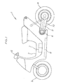
- Fig. 1 is a side view of an electric two wheeler, one embodiment of the electric motor vehicle.
- Fig. 2 is a drive circuit diagram of a motor controller, one embodiment of the first aspect.
- Fig. 3 is another drive circuit diagram of a motor controller, one embodiment of the first aspect.
- Fig. 4 is another drive circuit diagram of a motor controller, one embodiment of the first aspect.
- Fig. 5 is a plan view showing the arrangement of parts for an inverter device, one embodiment of the second aspect.
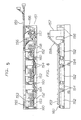
- Fig. 6 is a side view showing the arrangement of parts for an inverter device, one embodiment of the second aspect.
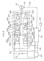
- Fig. 7 is a circuit diagram of an inverter device, one embodiment of the second aspect.
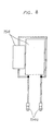
- Fig. 8 is a snubber capacitor assembly diagram, one embodiment of the second aspect.
- Fig. 9 is a side view showing a state of an inverter device of one embodiment of the second aspect attached to an electric two-wheeler.
- Fig. 10 is a circuit diagram of a semiconductor device protecting board, one embodiment of the second aspect.
- Fig. 11 is an assembly diagram of a semiconductor device protecting board, one embodiment of the second aspect.
- Fig. 12 is a mounting diagram of a semiconductor device protecting board, one embodiment of the second aspect.
- Fig. 13 is a drive circuit diagram of a conventional motor controller.
- Fig. 14 is another drive circuit diagram of a conventional motor controller.
- Fig. 15 is another drive circuit diagram of a conventional motor controller.
- Fig. 1 shows an electric two wheeler which is one embodiment of an electric motor vehicle.
- the invention will be described taking an electric two wheeler (including a scooter) as an example through the specification.
- An electric two wheeler 1 has wheels 3, 4 at the front and the rear of a body 2 in the same way as a conventional two wheeler driven by an engine.
- the front wheel 3 is operated by a handle 5, and the rear wheel 4 is not driven by an engine but a motor 6.
- the motor 6 is driven by a battery 7, and the motor rotation is controlled by a controller B.
- a controller B In Fig. 1, though some are not shown, an accelerator grip and a brake lever disposed an the handle 5, a brake mechanism, a power transmission mechanism, a suspension and others may be same as those for conventional two wheelers.
- Fig. 2 shows a drive circuit diagram of a motor controller according to this embodiment.
- power is not supplied to a control circuit 125, power sources 129a, 129b, 129c, and control circuits 130a, 130b, 130c when a key switch 124 is off, while power is supplied to the entire circuit of a conventional embodiment shown in Fig. 14.
- Fig. 2 when the key switch 124 is off, power is not supplied to the power sources 129a, 129b, 129c. Specifically, since the control circuits 130a, 130b, 130c are not operated, semiconductor switches 127a, 127b, 127c connected to the plus terminal of a battery have neither of positive or negative voltage applied to the control terminal, and on/off falls in an unsteady state. But, since a power source 129d is fed, control circuits 130d, 130e, 130f are operating, and since the control circuit 125 is not supplied with power, a transistor 228 of Fig. 15 is not turned on, and an electrifying signal 126 is not outputted.
- semiconductor switches 127d, 127e, 127f an the side of the minus terminal of the battery have a negative voltage applied to the control terminal, falling in an off state.
- a short circuit between the battery terminals can be surely avoided.
- power is consumed only by a power source 123, the power source 129d, the control circuits 130d, 130e, 130f, and the control terminals of the semiconductor switches 127d, 127e, 127f. And, the consumed power is controlled to be very small, so that its value may be practically neglected.
- Fig. 3 shows another embodiment.
- the power source which is fed when the key switch is off is the power source 129d, but in Fig. 3, modifications are made so that the power sources 129a, 129b, 129c are fed, and the power source 129d is fed only when the key switch 124 is on. Operation is the same as in the above embodiment.
- Fig. 4 shows still another embodiment.
- the power source 129 has power supplied from the power source 123 in Fig. 2, but modification is made to have power supplied from a battery 121 in Fig. 4. Taking a loss of the power source 123 into consideration, it is advantageous to have the power source 129d directly fed from the battery 121 as shown in Fig. 4.
- the motor is a DC brushless motor
- the semiconductor switch within the inverter device is a. MOSFET.
- the motor may be an induction motor
- the semiconductor switch may be a bipolar transistor, IGBT, or another element.
- the circuit supplied with power with the key switch off is limited to the minimum part required to avoid a short circuit of the battery, so that the consumed power is reduced extensively.
- necessity of cutting off the output of the battery using a relay is eliminated, thereby making it possible to achieve a light-weighted vehicle body.
- Fig. 5 is a plan view showing the arrangement of Parts of the inverter device of this embodiment.
- Fig. 6 is a side view of the above arrangement.
- the inverter of this embodiment consists of a radiator 151, semiconductor devices 152, a rectifying capacitor 157, snubber capacitors 154, a current detector 156, a temperature detector 155, a copper bar 153, and semiconductor device protecting boards 160.
- the three-phase bipolar type inverter consists of six semiconductor devices as shown in Fig. 7.
- a MOS-FET is used as the semiconductor devices 152 but an IGBT and other semiconductor devices may be used.
- the semiconductor devices 152 of this embodiment are modularized, and two top and bottom semiconductors are accommodated in one package.
- a drain and a source for supplying electric power from a power source to a motor are screw terminals, and a gate and a source for controlling are fasten terminals.
- Electric power is externally supplied and entered in the rectifying capacitor 157, flows a cable 158 and is supplied to each semiconductor device 152 through the copper bar 153.
- the copper bar has its surface insulated excepting parts which are attached to the semiconductor devices 152 in order to avoid a short circuit. Using the copper bar 153 allows a simple supply of electric power to respective semiconductor devices.
- the temperature detector 155 sends a signal to the control device to stop the operation of the inverter device when the semiconductor devices 152 are heated to a temperature above a permitted temperature.
- the current detector 156 sends a signal to the control device to stop the operation of the inverter device when electric current flows exceeding a permitted electric current of the semiconductor devices 152.
- a control signal to the inverter device is entered in the semiconductor device protecting boards 160 through a wire harness 159.
- the wire harness 159 is connected to the control device through a connector.
- the semiconductor devices 152 are disposed in a longitudinal direction side by side an the radiator 151, and the snubber capacitors 154 are mounted between the semiconductor devices.
- the snubber capacitors are structured as shown in Fig. 8. In this embodiment, two types of capacitors, or an electrolytic capacitor and a film capacitor, are used in parallel in order to expand the frequency band of a serge voltage to be absorbed.
- the snubber capacitors may be structured by one type of or three or more types of capacitors depending on the frequency of serge generated. Two capacitors are connected by soldering and connected between plus and minus of the power source with crimp-style terminals 154a.
- the inverter device can be structured in crosswise.
- the inverter device can be disposed in the lower part of the step of an electric two wheeler as shown in Fig. 9.
- the lower part of the step receives the best air flow when the electric two wheeler is travelling, cooling efficiency is excellent, and therefore, the volume of the radiator 151 can be made small.
- the snubber capacitors 154 By disposing the snubber capacitors 154 between the semiconductor devices 152, they can be disposed in a short distance from the position of the semiconductor devices 152, so that good electric characteristics can be obtained.
- the lead wire of the snubber capacitors is connected to the terminal of the semiconductor devices by taking workability into consideration, but when it is connected to the copper bar 153 in the shortest distance, much better electric characteristics can be obtained.
- the snubber capacitor is a part which is easily affected by a mechanical impact. Therefore, by disposing as in this embodiment, an external mechanical impact is received by the radiator 151 and the copper bar 153 which are not affected by such a mechanical impact, and the snubber capacitors 154 can be protected.
- a voltage regulation diode 160b is disposed to prevent the breakdown of the gate terminal of the semiconductor devices 152 which may be caused by overvoltage.
- a resistor 160a is attached to prevent the breakdown due to malfunction of the semiconductor devices 152 if a control signal is not entered in the semiconductor device protecting board 160 due to breakage or the like of the wire harness 159.
- the protecting circuit is made of a resistor and a voltage regulation diode, but the voltage regulation diode may be replaced by an element such as a serge absorber having the same function.
- the semiconductor device protecting board 160 has a rectangular appearance as shown in Fig. 11. Since the semiconductor device 152 of this embodiment has two semiconductors accommodated in one package, the semiconductor device protecting board 160 has two sets of elements mounted.
- the reference numeral 160c represents holes which are designed to insert the fasten terminals for the source and the gate of the semiconductor device 152.
- Fig. 12 shows a state that the semiconductor device protecting board 160 is attached to the semiconductor device 152.
- the semiconductor device protecting board 160 has the gate and the source of the semiconductor device 152 inserted into the holes 160c and connected by soldering.
- a semiconductor device drive signal is entered through the wire harness 159.
- the inverter device can be minimized and disposed in the lower part of the step having good cooling efficiency. Since the breakdown of the semiconductor devices can be prevented even if the control device is separated from the inverter device, safety is improved. And, flexibility of the mounting place of the control device is increased, so that the same space as in the case of a vehicle with an internal combustion engine can be secured.
- This embodiment has been described an the three-phase bipolar type inverter device which is mounted on an electric two wheeler, but the same structure can be applied to three-phase unipolar, two-phase bipolar, and other type of inverters.
- the invention described above can be utilized for the holding and maintenance of motors and controllers for the electric motor vehicles using a motor, particularly for two wheelers and three wheelers such as motorcycles and scooters, and for the improvement of safety of electric motor vehicles.
Landscapes
- Engineering & Computer Science (AREA)
- Power Engineering (AREA)
- Transportation (AREA)
- Mechanical Engineering (AREA)
- Sustainable Development (AREA)
- Sustainable Energy (AREA)
- Life Sciences & Earth Sciences (AREA)
- Combustion & Propulsion (AREA)
- Chemical & Material Sciences (AREA)
- Electric Propulsion And Braking For Vehicles (AREA)
- Motor Or Generator Frames (AREA)
- Inverter Devices (AREA)
- Arrangement Or Mounting Of Propulsion Units For Vehicles (AREA)
Applications Claiming Priority (35)
| Application Number | Priority Date | Filing Date | Title |
|---|---|---|---|
| JP11912792 | 1992-05-12 | ||
| JP11912792 | 1992-05-12 | ||
| JP23969692 | 1992-09-08 | ||
| JP4239695A JPH0823653A (ja) | 1992-09-08 | 1992-09-08 | ステータ巻線及びその製造方法 |
| JP23969592 | 1992-09-08 | ||
| JP4239696A JPH0822914A (ja) | 1992-09-08 | 1992-09-08 | エンコーダ磁石及びその固定構造 |
| JP24091392 | 1992-09-09 | ||
| JP24091892 | 1992-09-09 | ||
| JP24091692 | 1992-09-09 | ||
| JP24091592 | 1992-09-09 | ||
| JP24091992 | 1992-09-09 | ||
| JP24091692 | 1992-09-09 | ||
| JP24092292 | 1992-09-09 | ||
| JP24091792 | 1992-09-09 | ||
| JP24092092 | 1992-09-09 | ||
| JP24091892 | 1992-09-09 | ||
| JP24091992 | 1992-09-09 | ||
| JP24091292 | 1992-09-09 | ||
| JP24092192 | 1992-09-09 | ||
| JP24092192 | 1992-09-09 | ||
| JP24091392 | 1992-09-09 | ||
| JP24092092 | 1992-09-09 | ||
| JP24092292 | 1992-09-09 | ||
| JP24091792 | 1992-09-09 | ||
| JP24091592 | 1992-09-09 | ||
| JP24091492 | 1992-09-09 | ||
| JP24091292 | 1992-09-09 | ||
| JP24091492 | 1992-09-09 | ||
| JP25489292 | 1992-09-24 | ||
| JP25489292 | 1992-09-24 | ||
| JP28372192 | 1992-09-29 | ||
| JP28372092 | 1992-09-29 | ||
| JP28372192 | 1992-09-29 | ||
| JP28372092 | 1992-09-29 | ||
| EP93911994A EP0640507B1 (fr) | 1992-05-12 | 1993-05-11 | Vehicule electrique |
Related Parent Applications (1)
| Application Number | Title | Priority Date | Filing Date |
|---|---|---|---|
| EP93911994A Division EP0640507B1 (fr) | 1992-05-12 | 1993-05-11 | Vehicule electrique |
Publications (2)
| Publication Number | Publication Date |
|---|---|
| EP1110802A2 true EP1110802A2 (fr) | 2001-06-27 |
| EP1110802A3 EP1110802A3 (fr) | 2001-07-11 |
Family
ID=27585961
Family Applications (3)
| Application Number | Title | Priority Date | Filing Date |
|---|---|---|---|
| EP93911994A Expired - Lifetime EP0640507B1 (fr) | 1992-05-12 | 1993-05-11 | Vehicule electrique |
| EP01103605A Withdrawn EP1110802A3 (fr) | 1992-05-12 | 1993-05-11 | Véhicule électrique |
| EP01103604A Withdrawn EP1110801A3 (fr) | 1992-05-12 | 1993-05-11 | Véhicule électrique |
Family Applications Before (1)
| Application Number | Title | Priority Date | Filing Date |
|---|---|---|---|
| EP93911994A Expired - Lifetime EP0640507B1 (fr) | 1992-05-12 | 1993-05-11 | Vehicule electrique |
Family Applications After (1)
| Application Number | Title | Priority Date | Filing Date |
|---|---|---|---|
| EP01103604A Withdrawn EP1110801A3 (fr) | 1992-05-12 | 1993-05-11 | Véhicule électrique |
Country Status (5)
| Country | Link |
|---|---|
| US (3) | US5900686A (fr) |
| EP (3) | EP0640507B1 (fr) |
| KR (1) | KR100334423B1 (fr) |
| CN (3) | CN1049868C (fr) |
| WO (1) | WO1993023266A1 (fr) |
Families Citing this family (97)
| Publication number | Priority date | Publication date | Assignee | Title |
|---|---|---|---|---|
| EP0640507B1 (fr) * | 1992-05-12 | 2003-04-16 | Seiko Epson Corporation | Vehicule electrique |
| FR2716769B1 (fr) * | 1994-02-28 | 1996-05-15 | Peugeot | Dispositif de commande et de contrôle d'un moteur électronique, support utilisable dans un tel dispositif et utilisation de ce support pour la réalisation d'une batterie d'éléments d'accumulateurs électriques. |
| JPH0898305A (ja) * | 1994-09-29 | 1996-04-12 | Seiko Epson Corp | 電気自動車の走行装置 |
| JPH10201210A (ja) * | 1997-01-10 | 1998-07-31 | Zexel Corp | ブラシレスモータ |
| CN1574558A (zh) * | 1997-07-19 | 2005-02-02 | 东京研发股份有限公司 | 电动机 |
| JP4154635B2 (ja) * | 1999-05-31 | 2008-09-24 | 株式会社デンソー | センサレス・ブラシレスdcモータ制御装置 |
| JP4346753B2 (ja) * | 1999-10-19 | 2009-10-21 | ヤマハ発動機株式会社 | 電動車両用モータ配線配索構造 |
| AU753411B2 (en) * | 1999-10-19 | 2002-10-17 | Lg Electronics Inc. | Structure of driving unit in drum type washing machine |
| FR2806223B1 (fr) * | 2000-03-10 | 2003-10-03 | Valeo Equip Electr Moteur | Machine electrique tournante polyphasee |
| US6326765B1 (en) | 2000-10-04 | 2001-12-04 | Vectrix Corporation | Electric scooter with on-board charging system |
| US6615118B2 (en) | 2001-03-27 | 2003-09-02 | General Electric Company | Hybrid energy power management system and method |
| US7231877B2 (en) | 2001-03-27 | 2007-06-19 | General Electric Company | Multimode hybrid energy railway vehicle system and method |
| US7448328B2 (en) | 2001-03-27 | 2008-11-11 | General Electric Company | Hybrid energy off highway vehicle electric power storage system and method |
| US9151232B2 (en) | 2001-03-27 | 2015-10-06 | General Electric Company | Control system and method |
| US9193268B2 (en) | 2001-03-27 | 2015-11-24 | General Electric Company | Hybrid energy power management system and method |
| US7185591B2 (en) | 2001-03-27 | 2007-03-06 | General Electric Company | Hybrid energy off highway vehicle propulsion circuit |
| US7430967B2 (en) | 2001-03-27 | 2008-10-07 | General Electric Company | Multimode hybrid energy railway vehicle system and method |
| US7137344B2 (en) | 2001-03-27 | 2006-11-21 | General Electric Company | Hybrid energy off highway vehicle load control system and method |
| JP2003052160A (ja) * | 2001-08-06 | 2003-02-21 | Tokyo R & D Co Ltd | モータ |
| US6670788B2 (en) * | 2002-04-17 | 2003-12-30 | Visteon Global Technologies, Inc. | Method and apparatus for maximizing hybrid vehicle energy management |
| US6798162B2 (en) | 2002-07-17 | 2004-09-28 | Siemens Vdo Automotive Inc. | 12/42 volt DC brush motor control system |
| US6752229B2 (en) * | 2002-07-23 | 2004-06-22 | Chien-Chang Ho | Vehicle with motor and engine |
| KR100456852B1 (ko) * | 2002-09-05 | 2004-11-10 | 현대자동차주식회사 | 차량 전장 시스템 |
| US20040089485A1 (en) * | 2002-11-08 | 2004-05-13 | Kramer Dennis A. | Vehicle drive arrangement having multiple-sized electric motors |
| JP3867060B2 (ja) * | 2003-03-28 | 2007-01-10 | 三菱電機株式会社 | 車両用電源システム |
| DE10349205A1 (de) * | 2003-10-23 | 2005-06-09 | Hilti Ag | Elektromotor mit Luftführung |
| US7341264B2 (en) * | 2003-10-30 | 2008-03-11 | Mark Swannie | Trailer hitch mounted reverse sensing system |
| US7237748B2 (en) * | 2003-12-15 | 2007-07-03 | Delos Aerospace, Llc | Landing gear method and apparatus for braking and maneuvering |
| FR2870055B1 (fr) * | 2004-04-30 | 2013-07-05 | Valeo Equip Electr Moteur | Machine electrique tournante polyphasee pour vehicule automobile, equipee de moyens magnetiques de suivi de la rotation du rotor de resistance mecanique amelioree |
| JP3944505B2 (ja) * | 2004-10-26 | 2007-07-11 | 三菱電機株式会社 | 回転電機及びその製造方法 |
| JP2007060762A (ja) * | 2005-08-23 | 2007-03-08 | Mitsubishi Electric Corp | 負荷駆動システムの故障検出装置 |
| ITBO20060339A1 (it) * | 2006-05-08 | 2007-11-09 | Spal Automotive Srl | Metodo per assemblare un motore elettrico e motore ottenuto con tale metodo |
| JP4179346B2 (ja) * | 2006-06-16 | 2008-11-12 | トヨタ自動車株式会社 | 充電制御装置およびそれを備えた車両 |
| ITGE20060078A1 (it) * | 2006-08-02 | 2008-02-03 | Selin Sistemi S P A | Sistema di controllo per veicoli a trazione elettrica. |
| GB0618729D0 (en) * | 2006-09-22 | 2006-11-01 | Hobby Roger B | Flux impulse motor |
| TWM318844U (en) * | 2007-03-30 | 2007-09-11 | Princeton Technology Corp | Device for driving a single phase motor |
| JP4297951B2 (ja) * | 2007-05-25 | 2009-07-15 | トヨタ自動車株式会社 | 車両の駆動システム |
| JP5356087B2 (ja) * | 2009-03-27 | 2013-12-04 | 本田技研工業株式会社 | 電動車両 |
| JP5327646B2 (ja) * | 2009-06-24 | 2013-10-30 | 株式会社デンソー | 電子回路内蔵型モータ |
| JP4942803B2 (ja) * | 2009-10-28 | 2012-05-30 | 三菱電機株式会社 | エンジン始動装置 |
| JP5484868B2 (ja) * | 2009-11-19 | 2014-05-07 | カヤバ工業株式会社 | モータ |
| US8164226B2 (en) * | 2010-03-10 | 2012-04-24 | Digisine Energytech Co., Ltd. | Radiator for power generator coil |
| EP2623404B1 (fr) * | 2010-09-30 | 2019-11-06 | Suzuki Motor Corporation | Véhicule électrique à deux roues |
| DE102010047235A1 (de) * | 2010-10-04 | 2012-04-05 | Rolf Strothmann | Antrieb mit zuschaltbarem Lastelement |
| US9058578B2 (en) | 2010-12-24 | 2015-06-16 | Martin Kelly Jones | Systems and methods for battery remediation in connection with an electric powered mobiel thing (EPMT) |
| JP2012186893A (ja) * | 2011-03-04 | 2012-09-27 | Honda Motor Co Ltd | 電動車両 |
| CN102315820B (zh) * | 2011-08-22 | 2014-09-17 | 台州市金宇机电有限公司 | 适用于电动车的双动力转换器 |
| US8950539B2 (en) | 2012-01-03 | 2015-02-10 | Hero Motorcorp Ltd. | Lightweight integrated rear suspension and drive enclosure for a ridden motorized vehicle |
| US20130168171A1 (en) * | 2012-01-03 | 2013-07-04 | Erik Buell | Ridden vehicle with hybrid power system |
| USD698702S1 (en) | 2012-01-16 | 2014-02-04 | Fibres S.R.O. | Motorcycle |
| EP2634075A1 (fr) * | 2012-02-28 | 2013-09-04 | Fibres s.r.o. | Unité de commande de motocyclette électrique |
| DE102012205361A1 (de) * | 2012-04-02 | 2013-10-02 | Robert Bosch Gmbh | Bürstenlose elektrische Maschine mit vergrabenen Dauermagneten |
| JP2013219925A (ja) * | 2012-04-09 | 2013-10-24 | Toyota Motor Corp | 回転電機 |
| JP2013230053A (ja) * | 2012-04-26 | 2013-11-07 | Honda Motor Co Ltd | パワーコントロールユニット |
| CN103423187A (zh) * | 2012-05-25 | 2013-12-04 | 鸿富锦精密工业(武汉)有限公司 | 风扇转速控制系统 |
| JP5972099B2 (ja) * | 2012-08-09 | 2016-08-17 | 株式会社日立産機システム | アキシャルギャップ型回転電機 |
| KR20140038050A (ko) * | 2012-09-19 | 2014-03-28 | 주식회사 만도 | 전기 자전거 및 그 제어방법 |
| US20140124231A1 (en) | 2012-11-06 | 2014-05-08 | Milwaukee Electric Tool Corporation | Electric motor for a power tool |
| US10432045B2 (en) * | 2012-11-06 | 2019-10-01 | Milwaukee Electric Tool Corporation | Electric motor for a power tool |
| US20140167559A1 (en) * | 2012-12-14 | 2014-06-19 | Deere & Company | Electric machine stator securing method |
| JP5961283B2 (ja) * | 2012-12-25 | 2016-08-02 | 川崎重工業株式会社 | 電動車両 |
| JP5761243B2 (ja) * | 2013-03-29 | 2015-08-12 | 株式会社安川電機 | モータ制御装置および磁極位置推定方法 |
| JP2014212669A (ja) * | 2013-04-22 | 2014-11-13 | 三菱電機株式会社 | 全閉型回転電機および全閉型回転電機の製造方法 |
| US9445532B2 (en) * | 2013-05-09 | 2016-09-13 | Ford Global Technologies, Llc | Integrated electrical and thermal solution for inverter DC-link capacitor packaging |
| SG10201709590TA (en) | 2013-05-24 | 2018-01-30 | Delta T Corp | Ceiling fan with moisture protection features |
| JP6213229B2 (ja) * | 2013-12-26 | 2017-10-18 | 株式会社明電舎 | 電力変換装置の絶縁構造 |
| EP2921398B1 (fr) * | 2014-03-20 | 2017-02-22 | Askoll Eva S.R.L. | Unité de propulsion électrique et groupe de transmission de couple pour un scooter électrique et scooter correspondant |
| JP6310753B2 (ja) * | 2014-04-11 | 2018-04-11 | マブチモーター株式会社 | ブラシレスモータ |
| JP6425085B2 (ja) * | 2015-01-26 | 2018-11-21 | 株式会社デンソー | 回転電機及びその製造方法 |
| JP6700674B2 (ja) * | 2015-05-21 | 2020-05-27 | 三菱重工サーマルシステムズ株式会社 | 電動圧縮機用モータハウジングおよびそれを用いた車載用電動圧縮機 |
| EP3131198B1 (fr) * | 2015-08-10 | 2022-06-08 | Goodrich Actuation Systems Limited | Stratégie de commande d'un moteur double voie à aimant permanent à tolérance de pannes pour réduire le couple de traînée sous condition de défaillance |
| KR20180019687A (ko) | 2015-08-21 | 2018-02-26 | 미쓰비시덴키 가부시키가이샤 | 회전 전기기계 및 공기 조화 장치 |
| CN105644676A (zh) * | 2015-10-26 | 2016-06-08 | 浙江途尔车业有限公司 | 一种皮带传动式电动车 |
| JP2017081330A (ja) * | 2015-10-27 | 2017-05-18 | スズキ株式会社 | 電動二輪車用の外装構造 |
| JP6561770B2 (ja) * | 2015-10-27 | 2019-08-21 | スズキ株式会社 | 電動車両の構造 |
| CN105871145A (zh) * | 2016-03-15 | 2016-08-17 | 张斌 | 节电电机 |
| US10793001B2 (en) * | 2016-08-16 | 2020-10-06 | Zhejiang Easy Vehicle Co., Ltd. | Transmission and drive system for an electric vehicle |
| JP2018030465A (ja) * | 2016-08-25 | 2018-03-01 | Ntn株式会社 | 転舵輪用インホイールモータ駆動装置 |
| JP6976083B2 (ja) * | 2016-09-21 | 2021-12-01 | Ntn株式会社 | 車両動力補助システムおよび車両従動輪回生システム |
| JP2018090209A (ja) * | 2016-12-07 | 2018-06-14 | ヤマハ発動機株式会社 | 鞍乗型電動車両および電動パワーユニット |
| US20180172266A1 (en) * | 2016-12-21 | 2018-06-21 | Electric Horsepower Inc. | Electric resistance heater system and light tower |
| US10322688B2 (en) * | 2016-12-30 | 2019-06-18 | Textron Innovations Inc. | Controlling electrical access to a lithium battery on a utility vehicle |
| CN106849485B (zh) * | 2017-02-28 | 2022-06-28 | 唐凌霄 | 主动驱动单元 |
| CN109510364B (zh) * | 2017-09-15 | 2021-04-16 | 日本电产株式会社 | 驱动装置 |
| EP3457541A1 (fr) * | 2017-09-15 | 2019-03-20 | Nidec Corporation | Dispositif de conduite |
| USD860177S1 (en) * | 2017-11-07 | 2019-09-17 | Intrepid Control Systems, Inc. | Communication unit for a vehicular network |
| US20190165638A1 (en) * | 2017-11-29 | 2019-05-30 | Gp Enterprises Co., Ltd | Electric Motor Back Cover with a Sealing Structure |
| US11866117B2 (en) | 2019-01-16 | 2024-01-09 | Livewire Ev, Llc | Motorcycle with virtual braking and virtual clutch |
| EP3764375B1 (fr) * | 2019-07-09 | 2023-11-29 | Etel S.A. | Bouchon magnétique pour système de mouvement rotatif |
| US11190080B2 (en) * | 2019-09-30 | 2021-11-30 | Kuo-Tsun Lin | Ceiling fan motor housing with L-shaped positioning member with horizontal portion to support bottom end of cover |
| JP7679361B2 (ja) * | 2020-04-10 | 2025-05-19 | 株式会社半導体エネルギー研究所 | 二次電池の制御システム、制御回路、及びそれらを用いた車両 |
| CN213999286U (zh) * | 2020-04-11 | 2021-08-20 | 东莞市力宸机电科技有限公司 | 一种冲击扳手的冲击接触面形状 |
| CN114268183A (zh) | 2020-09-15 | 2022-04-01 | 佛山市威灵洗涤电机制造有限公司 | 电动机及洗衣机 |
| EP4007129A4 (fr) | 2020-09-15 | 2022-12-07 | Foshan Welling Washer Motor Manufacturing Co., Ltd. | Moteur électrique et machine à laver |
| US11299059B1 (en) | 2021-10-20 | 2022-04-12 | Future Motion, Inc. | Self-stabilizing skateboard |
| US12545351B2 (en) * | 2023-09-20 | 2026-02-10 | Future Motion, Inc. | Vibrational notification of motor conditions in a self-balancing electric vehicle |
| US20250364862A1 (en) * | 2024-05-22 | 2025-11-27 | Air Cool Industrial Co., Ltd. | Motor housing structure for ceiling fan |
Family Cites Families (93)
| Publication number | Priority date | Publication date | Assignee | Title |
|---|---|---|---|---|
| US2571907A (en) * | 1946-08-15 | 1951-10-16 | Westinghouse Electric Corp | Convertible motor |
| US3166685A (en) * | 1959-11-03 | 1965-01-19 | Weston Instruments Inc | Dual encapsulated stators |
| US3005357A (en) * | 1960-06-01 | 1961-10-24 | Holo Flite Int Inc | Motorized pulleys |
| US3238805A (en) * | 1963-02-18 | 1966-03-08 | John D Rieser | Uni-mount gearmotored pulley and its readying facilities |
| FR1393802A (fr) * | 1964-04-24 | 1965-03-26 | Licentia Gmbh | Procédé de centrage de corps rotatifs par rapport à des pièces de machines fixes au moyen d'une couche intermédiaire servant à l'ajustage précis, notamment pour le centrage de rotor de petits moteurs électriques par rapport au stator |
| JPS4219153Y1 (fr) * | 1964-09-03 | 1967-11-06 | ||
| DE1513735B2 (de) * | 1966-03-17 | 1970-10-29 | Appt, Erich, 7000 Stuttgart-Sil lenbuch | Preßwerkzeug für WiekelkKpfe von Elektromaschinen |
| US3555319A (en) * | 1969-03-05 | 1971-01-12 | Franklin Electric Co Inc | Submersible electric motor |
| CH528171A (de) * | 1971-02-25 | 1972-09-15 | Bbc Brown Boveri & Cie | Wickelkopfpresse zum Pressen der Statorwickelköpfe elektrischer Maschinen |
| US3725707A (en) * | 1971-05-05 | 1973-04-03 | Black & Decker Mfg Co | Field sub-assembly for universal electric motors |
| US3760339A (en) * | 1971-05-05 | 1973-09-18 | Black & Decker Mfg Co | Connector for plug in field |
| IL37992A (en) * | 1971-10-22 | 1976-06-30 | Harry Zvi Tabor | Electric motor flywheel drive system particularly for electric road vehicles |
| US3748511A (en) * | 1971-12-13 | 1973-07-24 | Ametek Inc | Stator lead anchoring and splice-insulating slot insulator structure and method |
| JPS4992719U (fr) * | 1972-12-06 | 1974-08-10 | ||
| JPS4992719A (fr) * | 1972-12-29 | 1974-09-04 | ||
| US3921745A (en) * | 1973-07-23 | 1975-11-25 | Mcculloch Corp | Electric bicycle |
| JPS522898A (en) * | 1975-06-24 | 1977-01-10 | Daiki Gomme Kogyo Kk | Method for treatment of by_product brine in the equipment of washing s moke |
| DE2539091C2 (de) * | 1975-09-03 | 1985-06-13 | Robert Bosch Gmbh, 7000 Stuttgart | Schleifringanordnung |
| US3976965A (en) * | 1975-10-28 | 1976-08-24 | The Bendix Corporation | Paired coiled conductors compact-long life |
| JPS52133637A (en) * | 1976-05-01 | 1977-11-09 | Kawasaki Heavy Ind Ltd | Device for preventing motor cycle side stand from forgetting to release to run |
| JPS53127608A (en) * | 1977-04-13 | 1978-11-08 | Hitachi Ltd | Adjusting method of stacked thickness of iron core in rotor |
| JPS555044A (en) * | 1978-06-24 | 1980-01-14 | Ichinomiya Denki:Kk | Method of winding motor coil combined with plural coil, motor coil winder and motor with the same coil by the same method |
| JPS5543334U (fr) * | 1978-09-12 | 1980-03-21 | ||
| JPS5947804B2 (ja) * | 1978-09-20 | 1984-11-21 | 松下電器産業株式会社 | 燃焼装置 |
| JPS5563494A (en) * | 1978-11-06 | 1980-05-13 | Hitachi Ltd | Air cushion device |
| JPS5563543A (en) * | 1978-11-06 | 1980-05-13 | Mitsubishi Electric Corp | Canned motor |
| JPS55152578U (fr) * | 1979-04-17 | 1980-11-04 | ||
| JPS55148391A (en) * | 1979-05-10 | 1980-11-18 | Matsushita Electric Works Ltd | Device for firing discharge lamp |
| JPS55152578A (en) * | 1979-05-12 | 1980-11-27 | Iony Kk | Cereal grain selector and its selecting method |
| DE2936020A1 (de) * | 1979-09-06 | 1981-04-02 | Robert Bosch Gmbh, 7000 Stuttgart | Elektrische maschine |
| JPS5929514B2 (ja) * | 1979-09-29 | 1984-07-20 | 新明和工業株式会社 | 粉粒体運搬車における排出口開閉装置 |
| JPS5657684U (fr) * | 1979-10-12 | 1981-05-18 | ||
| JPS5686059A (en) * | 1979-12-17 | 1981-07-13 | Mitsubishi Electric Corp | Manufacture of stator |
| JPS56107702A (en) * | 1980-01-30 | 1981-08-26 | Nissan Motor Co Ltd | Device for preventing malfunctioned starting up of battery vehicle |
| JPS5634549Y2 (fr) * | 1980-04-18 | 1981-08-14 | ||
| JPS56169765U (fr) * | 1980-05-16 | 1981-12-15 | ||
| JPS5826427B2 (ja) * | 1980-05-28 | 1983-06-02 | 日立化成工業株式会社 | 無電解銅めっき方法 |
| JPS57101551U (fr) * | 1980-12-10 | 1982-06-22 | ||
| JPS57101551A (en) * | 1980-12-11 | 1982-06-24 | Matsushita Electric Works Ltd | Manufacture of coil unit of coreless type armature |
| JPS57115555U (fr) * | 1981-01-07 | 1982-07-17 | ||
| JPS57115555A (en) * | 1981-01-10 | 1982-07-19 | Canon Inc | Photoconductive material |
| JPS58108903A (ja) * | 1981-12-23 | 1983-06-29 | Sanyo Electric Co Ltd | 電動車 |
| JPS58156393A (ja) * | 1982-03-12 | 1983-09-17 | Mitsui Toatsu Chem Inc | 塩水精製方法 |
| JPS58156393U (ja) * | 1982-04-12 | 1983-10-19 | 株式会社日立製作所 | 静止形変換装置 |
| JPS59107582A (ja) * | 1982-12-13 | 1984-06-21 | Fuji Photo Film Co Ltd | 半導体光検出装置の製造方法 |
| JPS59107582U (ja) * | 1983-01-08 | 1984-07-19 | 三菱電機株式会社 | 磁石モ−タの界磁装置 |
| FR2547622B1 (fr) * | 1983-06-16 | 1985-11-22 | Leroy Andre | Machine volumetrique a surface statorique particuliere |
| JPS6011601U (ja) * | 1983-06-30 | 1985-01-26 | 株式会社豊田自動織機製作所 | デツドマンスイツチ付きバツテリ車の安全装置 |
| JPS6069503A (ja) * | 1983-09-27 | 1985-04-20 | Hidehiko Yamada | 鋼板端部の形状測定方法 |
| JPS6069503U (ja) * | 1983-10-20 | 1985-05-17 | 日産自動車株式会社 | 電気自動車の走行制御装置 |
| JPS60134498A (ja) * | 1983-12-22 | 1985-07-17 | 富士通株式会社 | 電子部品の製造方法 |
| US4679484A (en) * | 1984-08-06 | 1987-07-14 | Westinghouse Electric Corp. | Electromagnetic launcher rail temperature reduction through controlled breech current injection |
| JPS6152146A (ja) * | 1984-08-20 | 1986-03-14 | Matsushita Electric Ind Co Ltd | 電動機 |
| JPS61159896A (ja) * | 1985-01-07 | 1986-07-19 | Matsushita Electric Ind Co Ltd | スピ−カ装置 |
| JPS61159896U (fr) * | 1985-03-23 | 1986-10-03 | ||
| US4727828A (en) * | 1985-03-29 | 1988-03-01 | Komatsu Zenoah Company | Portable engine unit |
| JPS6268055A (ja) * | 1985-09-20 | 1987-03-27 | Hitachi Ltd | モ−タ |
| US4713568A (en) * | 1985-09-26 | 1987-12-15 | Siemens Aktiengesellschaft | Closed motor/transmission unit |
| JPS6288444A (ja) * | 1985-10-15 | 1987-04-22 | Nippon Telegr & Teleph Corp <Ntt> | エコ−キヤンセラ制御方式 |
| JPS6288444U (fr) * | 1985-11-20 | 1987-06-05 | ||
| JPS62125349A (ja) * | 1985-11-27 | 1987-06-06 | Fuji Photo Film Co Ltd | ハロゲン化銀カラ−写真感光材料 |
| JPS62125349U (fr) * | 1986-01-29 | 1987-08-08 | ||
| JPS633645A (ja) * | 1986-06-23 | 1988-01-08 | Toshiba Corp | 半導体変換器 |
| ATE65417T1 (de) * | 1986-07-10 | 1991-08-15 | Duphar Int Res | Halter fuer eine mehrzahl von injektionsspritzen. |
| JPS6324956U (fr) * | 1986-08-01 | 1988-02-18 | ||
| JPH0830169B2 (ja) * | 1986-08-19 | 1996-03-27 | 日本合成ゴム株式会社 | コ−テイング用組成物 |
| JPS6348363U (fr) * | 1986-09-10 | 1988-04-01 | ||
| US5148001A (en) * | 1986-12-11 | 1992-09-15 | The Lincoln Electric Company | System and method of short circuiting arc welding |
| US4835360A (en) * | 1986-12-11 | 1989-05-30 | The Lincoln Electric Company | Method and device for controlling a short circuiting type welding system |
| JPS63162327A (ja) * | 1986-12-25 | 1988-07-05 | Toyo Electric Mfg Co Ltd | 電気駆動車両の車輪駆動装置 |
| JPS63174531A (ja) * | 1987-01-12 | 1988-07-19 | Shibaura Eng Works Co Ltd | モ−タの固定子鉄心部材 |
| GB2204287B (en) * | 1987-03-31 | 1991-04-17 | Hitachi Ltd | Electric power steering control system |
| JPH01171564A (ja) * | 1987-12-28 | 1989-07-06 | Jiekusu Kk | 搾乳器 |
| JP2525030Y2 (ja) * | 1987-07-30 | 1997-02-05 | 杉国工業株式会社 | 電動式車両の駆動輪 |
| JPH01286781A (ja) * | 1988-05-10 | 1989-11-17 | Fanuc Ltd | 感熱素子内蔵型半導体モジュール |
| JP2503199B2 (ja) * | 1988-05-10 | 1996-06-05 | シャープ株式会社 | 現像装置 |
| JPH01171564U (fr) * | 1988-05-20 | 1989-12-05 | ||
| JPH0297234A (ja) * | 1988-09-30 | 1990-04-09 | Toshiba Lighting & Technol Corp | 二次電池充電回路 |
| US5222572A (en) * | 1989-07-13 | 1993-06-29 | Honda Giken Kogyo Kabushiki Kaisha | Electric motor driven vehicle and power unit thereof |
| US4961018A (en) * | 1989-08-11 | 1990-10-02 | Wayne/Scott Fetzer Company | Enclosed pump motor and wiring thereof |
| JPH044703A (ja) * | 1990-04-18 | 1992-01-09 | Nippon Steel Corp | 二輪車 |
| US5036930A (en) * | 1990-05-17 | 1991-08-06 | Bisel Charley W | Electromagnetically powered engine apparatus and method |
| JP2932607B2 (ja) * | 1990-05-23 | 1999-08-09 | 日産自動車株式会社 | 電気自動車 |
| JP2980942B2 (ja) * | 1990-05-24 | 1999-11-22 | 三信工業株式会社 | 船外機の分離潤滑装置 |
| JPH0434835A (ja) * | 1990-05-31 | 1992-02-05 | Toshiba Lighting & Technol Corp | 蛍光ランプ |
| JPH0434835U (fr) * | 1990-07-09 | 1992-03-24 | ||
| US5285862A (en) * | 1992-03-16 | 1994-02-15 | Toyota Jidosha Kabushiki Kaisha | Power supply system for hybrid vehicles |
| US5182508A (en) * | 1992-04-16 | 1993-01-26 | Westinghouse Electric Corp. | Reconfigurable AC induction motor drive for battery-powered vehicle |
| US5528721A (en) * | 1992-05-04 | 1996-06-18 | John Svoboda | Direct current motor speed control apparatus |
| EP0640507B1 (fr) * | 1992-05-12 | 2003-04-16 | Seiko Epson Corporation | Vehicule electrique |
| JP2861680B2 (ja) * | 1992-10-13 | 1999-02-24 | 株式会社日立製作所 | 電気自動車用故障検出法及びそれを用いたフェールセイフ制御方法 |
| US5345154A (en) * | 1993-02-26 | 1994-09-06 | General Electric Company | Electric continuously variable transmission and controls for operation of a heat engine in a closed-loop power-control mode |
| US5341075A (en) * | 1993-03-10 | 1994-08-23 | A.C. Propulsion, Inc. | Combined motor drive and battery recharge system |
-
1993
- 1993-05-11 EP EP93911994A patent/EP0640507B1/fr not_active Expired - Lifetime
- 1993-05-11 US US08/335,707 patent/US5900686A/en not_active Expired - Lifetime
- 1993-05-11 EP EP01103605A patent/EP1110802A3/fr not_active Withdrawn
- 1993-05-11 WO PCT/JP1993/000620 patent/WO1993023266A1/fr not_active Ceased
- 1993-05-11 CN CN93105389A patent/CN1049868C/zh not_active Expired - Lifetime
- 1993-05-11 EP EP01103604A patent/EP1110801A3/fr not_active Withdrawn
-
1994
- 1994-11-12 KR KR1019940704060A patent/KR100334423B1/ko not_active Expired - Fee Related
-
1999
- 1999-02-04 US US09/244,900 patent/US6054818A/en not_active Expired - Lifetime
- 1999-02-04 US US09/244,899 patent/US6037726A/en not_active Expired - Lifetime
- 1999-04-15 CN CN99105214A patent/CN1109616C/zh not_active Expired - Fee Related
- 1999-04-15 CN CN99105215A patent/CN1105657C/zh not_active Expired - Fee Related
Also Published As
| Publication number | Publication date |
|---|---|
| CN1109616C (zh) | 2003-05-28 |
| EP0640507A1 (fr) | 1995-03-01 |
| CN1105657C (zh) | 2003-04-16 |
| US5900686A (en) | 1999-05-04 |
| EP0640507B1 (fr) | 2003-04-16 |
| CN1230496A (zh) | 1999-10-06 |
| US6037726A (en) | 2000-03-14 |
| WO1993023266A1 (fr) | 1993-11-25 |
| CN1049868C (zh) | 2000-03-01 |
| EP1110801A3 (fr) | 2001-07-11 |
| EP1110802A3 (fr) | 2001-07-11 |
| EP0640507A4 (fr) | 1998-07-29 |
| CN1105638A (zh) | 1995-07-26 |
| US6054818A (en) | 2000-04-25 |
| EP1110801A2 (fr) | 2001-06-27 |
| KR950701584A (ko) | 1995-04-28 |
| KR100334423B1 (ko) | 2002-10-11 |
| CN1230495A (zh) | 1999-10-06 |
| HK1018163A1 (en) | 1999-12-10 |
Similar Documents
| Publication | Publication Date | Title |
|---|---|---|
| JP5553935B2 (ja) | 電動車両制御装置 | |
| US6054818A (en) | Electric motor vehicle | |
| CN101110554B (zh) | 电力变换装置 | |
| EP2571147B1 (fr) | Dispositif d'entraînement électrique et dispositif de direction assistée électrique doté dudit dispositif | |
| EP1266801B1 (fr) | Unité de commande de puissance pour un véhicule | |
| JP4567029B2 (ja) | 電力変換装置 | |
| EP2482441B1 (fr) | Compresseur motorisé intégré dans un onduleur | |
| US20140035445A1 (en) | Rotating electric machine and electric power steering apparatus | |
| US7410020B2 (en) | Interlock device for high-voltage apparatus | |
| JP3031669B2 (ja) | 電力用回路モジュール | |
| KR20110135233A (ko) | 자동차의 인버터용 커패시터 | |
| JP2004312853A (ja) | 車両駆動ユニット及び車両駆動装置 | |
| JP2009005462A (ja) | 電力変換装置 | |
| US6571895B2 (en) | Electrical machine, and a drive arrangement for a vehicle | |
| JP2009106046A (ja) | 自動車用電力変換装置 | |
| CN100415561C (zh) | 电动车辆的电源装置 | |
| EP4380015A1 (fr) | Dispositif d'entraînement de véhicule | |
| WO2022113115A1 (fr) | Véhicule intelligent | |
| JP2005529265A (ja) | 電気機械を有する自動車用駆動システム | |
| JP4363900B2 (ja) | 車両用インバータ装置 | |
| JP4487962B2 (ja) | インバータ装置 | |
| FR2847858B1 (fr) | Systeme de regulation electrique du dispositif de transmission de mouvement pour un vehicule automobile | |
| TWI924937B (zh) | 用於具有電驅動單元之兩輪車的電池端子及兩輪車之電氣組件之配置 | |
| JP2000083310A (ja) | 電気接続箱の実装構造 | |
| US12501714B2 (en) | Semiconductor device, power module, inverter device, and electric vehicle |
Legal Events
| Date | Code | Title | Description |
|---|---|---|---|
| PUAI | Public reference made under article 153(3) epc to a published international application that has entered the european phase |
Free format text: ORIGINAL CODE: 0009012 |
|
| PUAL | Search report despatched |
Free format text: ORIGINAL CODE: 0009013 |
|
| AC | Divisional application: reference to earlier application |
Ref document number: 640507 Country of ref document: EP |
|
| AK | Designated contracting states |
Kind code of ref document: A2 Designated state(s): DE FR GB IT |
|
| AK | Designated contracting states |
Kind code of ref document: A3 Designated state(s): DE FR GB IT |
|
| RIC1 | Information provided on ipc code assigned before grant |
Free format text: 7B 60L 11/18 A, 7B 60L 3/00 B |
|
| 17P | Request for examination filed |
Effective date: 20011022 |
|
| AKX | Designation fees paid |
Free format text: DE FR GB IT |
|
| 17Q | First examination report despatched |
Effective date: 20030218 |
|
| GRAP | Despatch of communication of intention to grant a patent |
Free format text: ORIGINAL CODE: EPIDOSNIGR1 |
|
| GRAS | Grant fee paid |
Free format text: ORIGINAL CODE: EPIDOSNIGR3 |
|
| STAA | Information on the status of an ep patent application or granted ep patent |
Free format text: STATUS: THE APPLICATION IS DEEMED TO BE WITHDRAWN |
|
| 18D | Application deemed to be withdrawn |
Effective date: 20041201 |