EP1114357B1 - Elektronische zeitmessvorrichtung mit zeitangabe auf einem dezimalsystem basierend - Google Patents
Elektronische zeitmessvorrichtung mit zeitangabe auf einem dezimalsystem basierend Download PDFInfo
- Publication number
- EP1114357B1 EP1114357B1 EP99938115A EP99938115A EP1114357B1 EP 1114357 B1 EP1114357 B1 EP 1114357B1 EP 99938115 A EP99938115 A EP 99938115A EP 99938115 A EP99938115 A EP 99938115A EP 1114357 B1 EP1114357 B1 EP 1114357B1
- Authority
- EP
- European Patent Office
- Prior art keywords
- control pulses
- auxiliary control
- frequency
- electronic timepiece
- pulses
- Prior art date
- Legal status (The legal status is an assumption and is not a legal conclusion. Google has not performed a legal analysis and makes no representation as to the accuracy of the status listed.)
- Expired - Lifetime
Links
- 238000001514 detection method Methods 0.000 claims description 9
- 238000011144 upstream manufacturing Methods 0.000 claims description 8
- 230000005764 inhibitory process Effects 0.000 claims description 7
- 230000000295 complement effect Effects 0.000 claims description 4
- 230000000903 blocking effect Effects 0.000 claims description 2
- 230000002401 inhibitory effect Effects 0.000 claims 1
- 238000012360 testing method Methods 0.000 description 10
- 101000771022 Trichoderma longibrachiatum Chlorophenol O-methyltransferase Proteins 0.000 description 9
- 238000010586 diagram Methods 0.000 description 4
- 238000006243 chemical reaction Methods 0.000 description 3
- 238000012937 correction Methods 0.000 description 3
- 239000010453 quartz Substances 0.000 description 3
- VYPSYNLAJGMNEJ-UHFFFAOYSA-N silicon dioxide Inorganic materials O=[Si]=O VYPSYNLAJGMNEJ-UHFFFAOYSA-N 0.000 description 3
- 230000008901 benefit Effects 0.000 description 2
- 230000015572 biosynthetic process Effects 0.000 description 2
- 238000000034 method Methods 0.000 description 2
- 230000008569 process Effects 0.000 description 2
- 238000012549 training Methods 0.000 description 2
- VZZBCNXVZFAIQX-UHFFFAOYSA-N bms-986260 Chemical compound ClC=1C=C(C=CC=1F)C=1N=CN(C=1C=1C=CC=2N(N=1)C(=CN=2)C#N)CCO VZZBCNXVZFAIQX-UHFFFAOYSA-N 0.000 description 1
- 238000011161 development Methods 0.000 description 1
- 230000000694 effects Effects 0.000 description 1
- 238000012986 modification Methods 0.000 description 1
- 230000004048 modification Effects 0.000 description 1
Images


Classifications
-
- G—PHYSICS
- G04—HOROLOGY
- G04G—ELECTRONIC TIME-PIECES
- G04G99/00—Subject matter not provided for in other groups of this subclass
-
- G—PHYSICS
- G04—HOROLOGY
- G04G—ELECTRONIC TIME-PIECES
- G04G3/00—Producing timing pulses
- G04G3/02—Circuits for deriving low frequency timing pulses from pulses of higher frequency
Definitions
- the present invention relates to an electronic timepiece for displaying a plurality of time indications. More particularly, the present invention relates to a timepiece for displaying at least a first and a second time indication, the first time indication being based on the system eure- H M S inute- econde (hereinafter after HMS).
- HMS system eure- H M S inute- econde
- US-A-4,926,400 discloses an electronic timepiece in accordance with the preamble of the independent claim 1.
- This exhibit watchmaking system allows the display of a first time indication based on the H-M-S system and a second time indication based on a non-decimal system in which time is divided into twenty-five 25th of a day.
- Table 1 col. 3, of this document, one day (24 hours) is divided into 25 "hours” of 60 "minutes each, each" minute " comprising 57.6 seconds.
- At each "minute”, 2.4 seconds are thus “saved” to form an additional simulated time.
- the trends the time indications "24h” and "25h” are identical. Without additional indications, the user of such a timepiece will not be able to so clearly differentiate these two time indications.
- An object of the present invention is therefore to propose a part electronic timepiece for displaying at least one first and a second time indication, and by means of which the user can clearly and quickly identify and differentiate hourly indications displayed.
- the present invention relates to a timepiece electronic device for displaying at least a first and a second time indication whose characteristics are set out in the claim independent 1.
- the solution recommended by the present invention allows so clearly differentiate the first time indication from the second of in that the first and second time indications are based on different systems.
- the conventionally used H-M-S system consists in dividing the day in 24 hours, 1 hour being divided in 60 minutes, and 1 minute in 60 seconds.
- a division of time based on the decimal system consists of counterpart to divide the day, no longer according to the conventional scheme above, but successively, in tenths of a day (equivalent to 2.4 hours or 144 minutes), themselves divided into hundredths of a day (equivalents at 14.4 minutes or 864 seconds), then in thousandths of a day (equivalent to 86.4 seconds), etc.
- the second time indication requires only three digits ("000” to "999") to be displayed and is thus clearly distinguished from a time indication conventionally based on the H-M-S system typically displayed in the format "HH: MM". The risks of confusion when reading time indications are thus greatly reduced.
- the atypical format of the second time indication is example particularly suitable for displaying a universal time to which the user can clearly refer without confusing it with a conventional time indication of the time zone in which it is located find.
- the decimal system is also an interesting alternative to system H-M-S conventionally in force because it allows to get rid conversion problems inherent to the H-M-S format. This alternative is more logical and understandable for the already familiar user of the decimal system.
- the electronic timepieces commonly comprise a time base, typically a quartz oscillator delivering pulses at a given frequency equivalent to a binary power, for example 32'768 Hz.
- a frequency divider circuit consisting of a succession of N cascade connected flip-flops, is coupled to the time base so as to output control pulses whose frequency is reduced by a factor. 2 N.
- these control pulses are thus used to control the respective displays of these time indications.
- control pulses for forming a time indication based on a decimal system in which the time is divided at least in thousandths of a day it is necessary to generate these at less at a frequency of 1 / 86.4 Hz or a decimal multiple of this frequency, that is to say 1 / 8.64 Hz for a division in ten thousandths of a day, 1 / 0.864 Hz for a division in hundred-thousandths of a day, etc.
- a trivial solution to this problem is to provide a basis for additional time to deliver pulses at a frequency specific corresponding to a multiple of the desired frequency, for example 10'000 Hz.
- a frequency divider circuit having for example a division ratio equivalent to 86'400 would thus make it possible to generate control pulses at a frequency of 1 / 8.64 Hz.
- This trivial solution implies the use of two chains of distinct divisions (base of time + frequency divider circuit) to display the first and second hourly indications.
- base time clock ie a time base delivering pulses at a frequency equivalent to a binary power.
- Means for generating clock pulses which could be used in the context of the present invention are for example presented in US-A-3,975,898, US-A-4,413,350, US-A-5,771,180, US-A-3,777,471 and US-A-3,284,715.
- the timepiece is advantageously adapted to derive the control pulses of the first and second time indications from the same time base.
- generation means adapted to deliver, from pulses auxiliary commands from the time base, the second pulses command for forming and displaying the second time indication.
- the timepiece can thus be particularly adapted to drift, to from pulses at 1 Hz from the time base at the output of the circuit frequency divider, second control pulses having a frequency of 1 / 86.4 Hz to form a second time indication at thousandth of a day, and this despite the fact that the division ratio of these frequency is not integer.
- Another advantage of the present invention thus lies in the fact only a single time base is used to generate the different control pulses of the first and second time indications and that it is therefore possible to adapt the electronics of a timepiece conventional so that it allows the display of a time indication based on the decimal system.
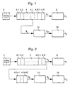
- FIG. 1 shows, in the form of a simplified block diagram, a timepiece constituting a first embodiment of the present invention.
- This timepiece comprises in series a time base 2, typically formed of a quartz oscillator, a frequency divider circuit 4 having N binary dividing stages 4.1 to 4.N and delivering first control pulses I 1 , and first display means 6 controlled by the first control pulses I 1 .
- the above-mentioned numerical values will be used as non-limiting examples.
- the first display means 6 are controlled by the first control pulses I 1 and are arranged in a conventional manner so that they allow the formation and display of a first time indication H 1 based on the HMS system.
- the timepiece according to the present invention further comprises generation means 14 delivering second control pulses I 2 whose frequency is determined by the adopted decimal division, for example 1 / 86.4 Hz in the case where a division in thousandths of a day is adopted.
- These generation means 14 are controlled by auxiliary control pulses I L originating from the time base 2 and delivered, in this embodiment, to the output of one of the binary division stages 4.1 to 4.N of the circuit frequency divider 4, this stage being indicated by the reference 4.L and can be chosen from the set of binary division stages 4.1 to 4.N.
- the frequency of the control auxiliary pulses I L is equivalent to the frequency of the pulses delivered by the time base 2 reduced by a factor of 2 L.
- second display means 16 In series with the generation means 14 are connected second display means 16. These second display means 16 are controlled by the second control pulses I 2 and are arranged so that they allow the formation and the displaying a second time indication H 2 based on the decimal system.
- FIG. 2 shows, in the form of a simplified block diagram, a timepiece constituting a second embodiment of the present invention.
- This timepiece comprises in series, the time base 2, the frequency divider circuit 4, the first and second display means 6 and 16, and the generation means 14 of the second control pulses I 2 .
- This timepiece further comprises N * additional binary division stages 4.N + 1 to 4.N + N * connected thereafter of the frequency divider circuit 4.
- the generation means 14 are controlled by auxiliary pulses of command I L also issued from the time base 2 and delivered, in this embodiment, to the output of the additional bit division stages 4.N + 1 to 4.N + N *.
- the frequency of the auxiliary control pulses I L is equivalent, in this case, to the frequency of the pulses delivered by the time base 2 reduced by a factor of 2 N + N *.
- FIGS. 1 and 2 thus make it possible to display a first time indication H 1 based on the HMS system, and a second time indication H 2 based on the decimal system.
- the second control pulses I 2 are thus generated from auxiliary control pulses I L originating from the time base 2.
- the timepiece according to the present invention further comprises correction means for adjusting the different time indications.
- correction means for adjusting the different time indications have not been described here and are not shown in Figures 1 and 2.
- the man of the profession will nevertheless be able to carry out these means of correction so that they allow each time indication to be suitably adjusted.
- display means may also be provided in such a way as to allow the training and the display of additional time indications based on the H-M-S system or the decimal system.
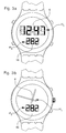
- FIGS. 3a and 3b show plan views of timepieces according to the present invention illustrating different possibilities of displaying the time indications H 1 and H 2 .
- the first display means 6 of the first time indication H 1 can be made in the form of a digital display, which can be used, for example, to display the time indication H 1 according to a conventional format "HH: MM".
- these first display means may for example comprise, as shown in Figure 3b, first and second needles driven by electromechanical means (not shown) and respectively allowing the display of hours and minutes.
- the second display means 16 of the second time indication H 2 are advantageously formed, as is illustrated in FIGS. 3a and 3b, of a digital display comprising, in this example, 3 digits so as to enable the display of the second time indication H 2 in thousandths of a day.
- These second display means 16 may, however, also be in the form of an analog needle display driven by electromechanical means similarly to the first display means 6 illustrated in Figure 3b.
- the second control pulses I 2 must be delivered at a frequency of 1 /86.4 Hz or 1 / 8.64 Hz respectively.
- the auxiliary control pulses I L are used, according to the present invention, to generate the second control pulses I 2 .
- the frequency of the auxiliary control pulses I L is determined by the binary division stage at the output of which they are delivered. According to the first embodiment described in FIG. 1, this frequency is thus equivalent to the frequency of the pulses delivered by the time base 2 reduced by a factor of 2 L. According to the second embodiment described in FIG. 2, this frequency is equivalent to the frequency of the pulses delivered by the time base 2 reduced by a factor of 2 N + N *.
- the frequency division ratio of the auxiliary control pulses I L by the frequency of the second control pulses I 2 defines a numerical value corresponding to the average number of auxiliary control pulses I L to be counted to generate a control pulse I 2 . Since the frequency of the pulses delivered by the time base 2 is typically equivalent to a binary power, the division ratio defines a non-integer numerical value due to the decimal division of the day.
- n and n + 1 respectively directly lower and higher than the division ratio mentioned above. These integers n and n + 1 thus correspond respectively to the integers directly below and above the average number of auxiliary control pulses I L to be counted to generate a control pulse I 2 .
- the second control pulses I 2 are generated at an average frequency corresponding to the desired frequency, for example 1 / 86.4 Hz or 1 / 8.64 Hz, n and n + 1 auxiliary control pulses I L are thus successively counted according to a determined counting sequence.
- This counting sequence is formed of a succession of counting operations of n and n + 1 auxiliary control pulses I L.
- the division ratio defined above determines the period as well as the number of counting operations after which the second control pulses I 2 are generated at the desired average frequency.
- This counting sequence is also preferably formed of so that the deviations generated during the counting sequence are reduced to a minimum.
- the frequency division ratio equals 86.4.
- the division ratio further defines that 5 control pulses I 2 should be generated over a period of 432 seconds.
- the counting sequence repeated 200 times over a period of 24 hours, is thus formed of a succession of 5 counting operations.
- I 2 is equivalent to 1 / 86.4 Hz.
- control pulses I 2 are preferably generated according to the following counting sequence:
- the maximum deviation generated during the counting sequence is thus limited to +/- 0.4 seconds, ie of the order of 0.5% of the period of the second control pulses I 2 .
- the frequency division ratio equals 10.8.
- the division ratio further defines that 5 control pulses I 2 should be generated over a period of 432 seconds.
- the counting sequence repeated 200 times over a period of 24 hours, is thus formed of a succession of 5 counting operations.
- I 2 is equivalent to 1 / 86.4 Hz.
- control pulses I 2 are preferably generated according to the following counting sequence:
- the maximum deviation generated during the counting sequence is thus limited to +/- 3.2 seconds, ie of the order of 4% of the period of the second control pulses I 2 .
- the frequency division ratio equals 8.64.
- the division ratio further defines that 25 control pulses I 2 should be generated over a period of 216 seconds.
- the counting sequence repeated 400 times over a period of 24 hours, is thus formed of a succession of counting operations.
- control pulses I 2 are preferably generated according to the following counting sequence:
- the maximum deviation generated during the counting sequence is thus limited to +/- 0.48 seconds, ie of the order of 5.5% of the period of the second control pulses I 2 .
- auxiliary control pulses I L determines, on the one hand, the precision with which the second control pulses I 2 are generated, and on the other hand the size of the registers / counters necessary for the counting of the auxiliary control pulses I L.
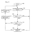
- FIG. 4 presents a flowchart for implementing the means generation 14 constituting a first embodiment according to the present invention.
- these generation means 14 can advantageously be produced in the form of an integrated circuit having a programmed microprocessor.
- the skilled person will know, from the indications provided here, carry out the programming of the microprocessor, so as to make him perform the functions described.
- a counter register COMPT is incremented at each control auxiliary pulse I L.
- This counter register COMPT comprises a number of bits sufficient to allow the counting of at least n + 1 auxiliary control pulses I L.
- this counter register COMPT comprises at least 7 bits.
- a first test is performed in block 404 so as to check whether the value of the counter register COMPT has reached the value n.
- the counter register COMPT is incremented at block 402 at each auxiliary control pulse I L , as long as the value of the latter is lower than the value n, this being indicated by the affirmative output of the test block 404.
- the negative output of the test block 406 leads to the third test indicated in block 408. At this stage, it is verified, according to the counting sequence, whether the counter register COMPT must be stopped at the value n. If necessary, a control pulse I 2 is generated at block 410, after the counting of n auxiliary control pulses I L. In the opposite case, the counter register COMPT is incremented at block 402 and, following the affirmative result of the test executed at block 406, the control pulse I 2 is then generated at block 410, ie after the counting of n + 1 pulses control auxiliaries I L.
- a table should be used representative of the counting sequence and accordingly comprising as many entries as there are counting operations.
- This table preferably comprises binary values representative of the counting operation to be performed, for example the binary value "0" if it is necessary to count n auxiliary control pulses I L or the binary value "1". if it is necessary to count n + 1 auxiliary control pulses I L.
- a binary word comprising as many bits as counting operations easily makes it possible to produce the table representative of the counting sequence.
- a register containing the value of the second time indication H 2 during display will preferably be used so as to determine which is the appropriate counting operation to be performed.
- the register containing the value of the second time indication H 2 currently being displayed makes it possible to define an indexing value of the various entries of the table by a simple calculation of the modulo.
- the modulo we mean by modulo the arithmetic operation giving the remainder of a division by a given number.
- control pulses I 2 are generated at an average frequency of 1 / 86.4 Hz from auxiliary control pulses IL at 1 Hz
- the counting sequence is preferably determined. so that 5 control pulses I 2 are generated according to the following counting sequence:
- This counting sequence can thus be represented by a 5-input table, preferably carried out using the following 5-bit binary word:
- test performed at block 408 is thus performed by searching the corresponding value in the table.
- a register will be used containing the value of the second time indication H 2 currently being displayed, or at least the value (0 to 9) of the displayed thousandths of a day.
- a modulo-5 operation on the value of this register thus makes it possible to obtain an indexing value (0 to 4) of the table.
- an alternative to using a table is to directly use the result of the modulo-5 operation on the register containing the value of the displayed thousandths of a day.
- the counting sequence is preferably determined so that 5 control pulses I 2 are generated according to the following counting sequence:
- This counting sequence can thus be represented by a table with 5 inputs, preferably carried out using the following 5-bit binary word:
- a register will preferably be used containing the value of the displayed thousandths of a day in order to obtain modulo-5 operation an indexing value (0 to 4) of the table.
- the counting sequence is preferably determined so that 25 control pulses I 2 are generated according to the following counting sequence:
- This counting sequence can thus be represented by an input table, preferably made using the following 25-bit binary word:
- test performed at block 408 is thus performed by searching for the corresponding value in this table.
- a register containing at least the value (0 to 99) thousandths and ten thousandths of a day displayed.
- An operation of modulo-25 on the value of this register thus makes it possible to obtain an indexing value (0 to 24) of the table.
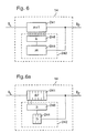
- FIG. 5 illustrates a second variant embodiment of the generation means 14 making it possible to deliver the second control pulses I 2 .
- these generation means 14 comprise a primary counter 141 arranged to count n auxiliary control pulses I L , and inhibition means 142 of the primary counter 141.
- the inhibition means 142 are controlled by the auxiliary control pulses I L and are located upstream of the primary counter 141 so as to periodically inhibit a predetermined number of auxiliary control pulses I L at the input of the latter.
- the second control pulses I 2 are delivered to the output of the primary counter 141.
- the inhibition means 142 preferably comprise a secondary counter 144 arranged to count m auxiliary control pulses I L , a detection logic circuit 146 coupled to the different stages of the secondary counter 144 so as to detect intermediate states of the latter (chosen from the states 0 to m-1) during which the auxiliary control pulses I L are inhibited, as well as an AND logic gate, indicated by the reference 148, comprising 2 inputs, one being inverted and connected to the output of the detection logic circuit 146 and the other receiving auxiliary control pulses I L.
- the inhibition means 142 thus make it possible to inhibit periodically, that is to say, during a period when m pulses I L are delivered, k auxiliary control pulses I L upstream of the primary counter 141.
- the detection logic 146 When one of the k intermediate states is detected by the detection logic 146, the latter thus returns a muting signal blocking the output of the logic AND gate for the duration of a control auxiliary pulse I L so that the primary counter 141 does not "see” this pulse and does not count it.
- the k intermediate states will be chosen so that they equidistant from each other, so as to minimize the differences generated.
- FIG. 5a illustrates a first example of the second variant of embodiment shown in FIG. 5 applied in the case where the second control pulses I 2 are generated at an average frequency of 1 / 86.4 Hz from of auxiliary control pulses I L having a frequency of 1 Hz, or in the case where the generation means 14 are connected to the output of the last binary division stage 4.N of the frequency divider circuit 4 (according to the first embodiment embodiment shown in Figure 1).
- control pulses I 2 are thus delivered to the output of the primary counter 141 during a period of 432 seconds, ie at the average frequency of 1 / 86.4 Hz.
- the counter by 86 can easily be realized by means of a 7-bit binary counter arranged to be initialized after 86 pulses.
- the counter by 216 requires an 8-bit counter arranged to be initialized after 216 pulses.
- control pulses I 2 are thus delivered to the output of the primary counter 141 during a period of 432 seconds, ie at the average frequency of 1 / 86.4 Hz.
- the counters by 10 and 27 thus require 4 and 5 bit counters respectively.
- FIG. 5c illustrates a third example of the second embodiment shown in FIG. 5 applied in the case where the second control pulses I 2 are generated at an average frequency of 1 / 8.64 Hz, that is 25 pulses over a period of 216 seconds, from auxiliary control pulses I L having a frequency of 1 Hz, or in the case where the generation means 14 are connected to the output of the last binary division stage 4 .N of the frequency divider circuit 4 (according to the first embodiment shown in Figure 1).
- control pulses I 2 are thus delivered to the output of the primary counter 141 during a period of 216 seconds, ie at the average frequency of 1 / 8.64 Hz.
- the counters by 8 and 27 thus require counters 3 and 5 bits respectively.
- the frequency of the control auxiliary pulses I L defines the precision at which the second control pulses I 2 are delivered. Indeed, the higher the frequency of the auxiliary control pulses I L is high, the greater the accuracy to which the second control pulses I 2 are delivered. However, it will be seen that this implies in return the use of counters comprising a large number of stages.
- FIG. 6 illustrates a third variant embodiment of the generating means 14 for delivering the second control pulses I 2 .
- these generation means 14 comprise a primary counter 241 arranged to count n + 1 auxiliary control pulses I L , and initialization means 242 coupled to the primary counter 241.
- the second control pulses I 2 are fed to the output of the primary counter 241 and are used to control the initialization means 242 so as to periodically initialize the primary counter 241 with a value k corresponding to a complementary number of auxiliary control pulses I L.
- the initialization means 242 preferably comprise a secondary counter 244 arranged to count m seconds control pulses I 2 and an initialization circuit 246 coupled to the different stages of the primary counter 241 so as to periodically initialize the latter, that is to say ie after m pulses I 2 have been delivered, with a value k corresponding to the complementary number of auxiliary control pulses I L necessary for the primary counter 241 to deliver the second control pulses I 2 at the appropriate average frequency.
- the primary counter 241 is initialized with a value k so as to compensate for the missing auxiliary control pulses I L.
- FIG. 6a illustrates an example of the third embodiment shown in FIG. 6 applied in the case where the second control pulses I 2 are generated at an average frequency of 1 / 86.4 Hz from auxiliary control pulses I L having a frequency of 1 Hz, or in the case where the generating means 14 are connected to the output of the last 4N binary division stage (4.15) of the frequency divider circuit 4 (in accordance with the first embodiment shown in Figure 1).
- control pulses I 2 are thus delivered to the output of the primary counter 241 during a period of 432 seconds, ie at the average frequency of 1 / 86.4 Hz.
- the 87 and 5 counters require counters 7 and 3 bits respectively.
- timepiece Accordingly, several modifications and / or improvements can be made to the timepiece according to the present invention without leaving of the frame of it. It will be recalled, in particular, that display means may be provided in such a way as to enable training and the display of additional time indications based on the H-M-S system or the decimal system.
Landscapes
- Physics & Mathematics (AREA)
- General Physics & Mathematics (AREA)
- Electric Clocks (AREA)
- Measuring Frequencies, Analyzing Spectra (AREA)
- Measurement Of Unknown Time Intervals (AREA)
Claims (16)
- Elektronisches Zeitmessgerät, das die Anzeige wenigstens einer ersten (H1) und einer zweiten (H2) Zeitangabe ermöglicht, wobei die erste Zeitangabe (H1) auf dem Stunden-Minuten-Sekunden-System (H-M-S-System) basiert, wobei das Zeitmessgerät eine Zeitbasis (2) umfasst, die Impulse an eine Frequenzteilerschaltung (4) liefert, die N binäre Teilerstufen (4.1 bis 4.N) umfasst und erste Steuerimpulse (I1) liefert, die ermöglichen, die erste Zeitangabe (H1) zu bilden und anzuzeigen, wobei das Zeitmessgerät außerdem Generatormittel (14) umfasst, die so beschaffen sind, dass sie anhand von Hilfssteuerimpulsen (IL), die von der Zeitbasis (2) stammen, zweite Steuerimpulse liefern, die ermöglichen, die zweite Zeitangabe (H2) zu bilden und anzuzeigen,
wobei das Zeitmessgerät dadurch gekennzeichnet ist, dass die zweite Zeitangabe (H2) auf einem Dezimalsystem basiert, in dem die Zeit wenigstens in Tausendstel eines Tages unterteilt ist, und dass die zweite Zeitangabe (H2) mittels dreier Ziffern angezeigt wird, so dass sie nicht mit der ersten Zeitangabe (H1) verwechselt werden kann. - Elektronisches Zeitmessgerät nach Anspruch 1, dadurch gekennzeichnet, dass die Generatormittel (14) so beschaffen sind, dass sie die Hilfssteuerimpulse (IL) sukzessive in einer Zählfolge zählen, die aus Zählvorgängen von n und n + 1 Hilfssteuerimpulsen (IL) gebildet ist, die in einer bestimmten Reihenfolge aufeinander folgen, derart, dass die Generatormittel (14) die zweiten Steuerimpulse (I2) mit einer mittleren Frequenz liefern, die ermöglicht, die zweite Zeitangabe (H2), die auf dem Dezimalsystem basiert, zu bilden, wobei n eine ganze Zahl ist, die streng kleiner als der Quotient aus der Frequenz der Hilfssteuerimpulse (IL) und der Frequenz der zweiten Steuerimpulse (I2) ist.
- Elektronisches Zeitmessgerät nach Anspruch 2, dadurch gekennzeichnet, dass die Zählvorgänge von n und n + 1 Hilfssteuerimpulsen (IL) in einer bestimmten Reihenfolge aufeinander folgen, derart, dass die zweiten Hilfssteuerimpulse (I2) mit minimalen Abständen geliefert werden.
- Elektronisches Zeitmessgerät nach Anspruch 2 oder 3, dadurch gekennzeichnet, dass die Zählfolge in einer Tabelle enthalten ist, die ebenso viele Einträge enthält, wie es Zählvorgänge gibt.
- Elektronisches Zeitmessgerät nach Anspruch 4, dadurch gekennzeichnet, dass die Tabelle aus einem binären Wort gebildet ist, in dem der binäre Wert "0" angibt, dass die Zählung von n Hilfssteuerimpulsen (IL) ausgeführt werden soll, und der binäre Wert "1" angibt, dass die Zählung von n + 1 Hilfssteuerimpulsen (IL) ausgeführt werden soll.
- Elektronisches Zeitmessgerät nach Anspruch 4 oder 5, dadurch gekennzeichnet, dass die Einträge der Tabelle durch ein Register indexiert sind, das einen Wert der zweiten Zeitangabe (H2) enthält.
- Elektronisches Zeitmessgerät nach Anspruch 2 oder 3, dadurch gekennzeichnet, dass die Zählvorgänge von n oder n + 1 Hilfssteuerimpulsen (IL) durch ein Register bestimmt werden, das einen Wert der zweiten Zeitangabe (H2) enthält.
- Elektronisches Zeitmessgerät nach Anspruch 1, dadurch gekennzeichnet, dass die Generatormittel (14) einen primären Zähler (141), der so beschaffen ist, dass er n Hilfssteuerimpulse (IL) zählt, und Mittel (142) zum Sperren des primären Zählers (141), die so beschaffen sind, dass sie periodisch k Hilfssteuerimpulse (IL) am Eingang des primären Zählers (141) sperren, umfassen, derart, dass der primäre Zähler (141) die zweiten Steuerimpulse (I2) mit einer mittleren Frequenz liefert, die ermöglicht, die zweite Zeitangabe (H2), die auf dem Dezimalsystem basiert, zu bilden, wobei n eine ganze Zahl streng kleiner als der Quotient aus der Frequenz der Hilfssteuerimpulse (IL) und der Frequenz der zweiten Steuerimpulse (I2) ist.
- Elektronisches Zeitmessgerät nach Anspruch 8, dadurch gekennzeichnet, dass die Sperrmittel (142) einen sekundären Zähler (144), der so beschaffen ist, dass er m Hilfssteuerimpulse (IL) zählt, eine Erfassungs-Logikschaltung (146), die mit dem sekundären Zähler (144) gekoppelt ist, derart, dass sie k Zwischenzustände dieses letzteren erfasst, und ein UND-Logikgatter (148), das 2 Eingänge umfasst, wovon einer invertiert ist und mit einem Ausgang der Erfassungs-Logikschaltung (146) verbunden ist und der andere die Hilfssteuerimpulse (IL) empfängt, umfassen, wobei die Erfassungs-Logikschaltung (146) ein Sperrsignal schickt, das das UND-Logikgatter (148) sperrt, wenn einer der k Zwischenzustände erfasst wird, derart, dass ein Hilfssteuerimpuls (IL) am Eingang des primären Zählers (141) gesperrt wird.
- Elektronisches Zeitmessgerät nach Anspruch 9, dadurch gekennzeichnet, dass die k Zwischenzustände in der Weise gewählt sind, dass sie jeweils den gleichen Abstand voneinander haben.
- Elektronisches Zeitmessgerät nach Anspruch 1, dadurch gekennzeichnet, dass die Generatormittel (14) einen primären Zähler (241), der so beschaffen ist, dass er n + 1 Hilfssteuerimpulse (IL) zählt, und Initialisierungsmittel (242), die mit dem primären Zähler (241) gekoppelt und so beschaffen sind, dass sie den primären Zähler (241) mit einem Wert k, der einer komplementären Anzahl von Hilfssteuerimpulsen (IL) entspricht, periodisch initialisieren, umfassen, derart, dass der primäre Zähler (241) die zweiten Steuerimpulse (I2) mit einer mittleren Frequenz liefert, die ermöglicht, die zweite Zeitangabe (H2), die auf dem Dezimalsystem basiert, zu bilden, wobei n + 1 eine ganze Zahl streng größer als der Quotient aus der Frequenz der Hilfssteuerimpulse (IL) und der Frequenz der zweiten Steuerimpulse (I2) ist.
- Elektronisches Zeitmessgerät nach Anspruch 11, dadurch gekennzeichnet, dass die Initialisierungsmittel (242) einen sekundären Zähler (244), der so beschaffen ist, dass er m zweite Steuerimpulse (I2) zählt, und eine Initialisierungsschaltung (246), die mit dem primären Zähler (241) gekoppelt ist, umfassen, wobei der sekundäre Zähler (244) nach jeweils m zweiten Steuerimpulsen (I2) ein Signal an die Initialisierungsschaltung (244) liefert, derart, dass der primäre Zähler (241) mit einem Wert k initialisiert wird.
- Elektronisches Zeitmessgerät nach einem der Ansprüche 1 bis 12, dadurch gekennzeichnet, dass die Hilfssteuerimpulse (IL) an einen Ausgang einer (4.L) der binären Teilerstufen (4.1 bis 4.N) der Frequenzteilerschaltung (4) geliefert werden.
- Elektronisches Zeitmessgerät nach einem der Ansprüche 1 bis 12, dadurch gekennzeichnet, dass die Hilfssteuerimpulse (IL) an einen Ausgang von N* zusätzlichen binären Teilerstufen (4.N + 1 bis 4.N + N*), die hinter der Frequenzteilerschaltung (4) und vor den Generatormitteln (14) angeschaltet sind, geliefert werden.
- Elektronisches Zeitmessgerät nach einem der Ansprüche 1 bis 12, dadurch gekennzeichnet, dass die Generatormittel (14) die zweiten Steuerimpulse (I2) mit einer mittleren Frequenz von 1/8,64 Hz liefern.
- Elektronisches Zeitmessgerät nach einem der Ansprüche 1 bis 12, dadurch gekennzeichnet, dass die Generatormittel (14) die zweiten Steuerimpulse (I2) mit einer mittleren Frequenz von 1/86,4 Hz liefern.
Applications Claiming Priority (3)
| Application Number | Priority Date | Filing Date | Title |
|---|---|---|---|
| CH176498 | 1998-08-28 | ||
| CH176498 | 1998-08-28 | ||
| PCT/CH1999/000387 WO2000013067A1 (fr) | 1998-08-28 | 1999-08-24 | Piece d'horlogerie electronique comportant une indication horaire fondee sur un system decimal |
Publications (2)
| Publication Number | Publication Date |
|---|---|
| EP1114357A1 EP1114357A1 (de) | 2001-07-11 |
| EP1114357B1 true EP1114357B1 (de) | 2005-05-04 |
Family
ID=4218029
Family Applications (1)
| Application Number | Title | Priority Date | Filing Date |
|---|---|---|---|
| EP99938115A Expired - Lifetime EP1114357B1 (de) | 1998-08-28 | 1999-08-24 | Elektronische zeitmessvorrichtung mit zeitangabe auf einem dezimalsystem basierend |
Country Status (13)
| Country | Link |
|---|---|
| US (1) | US6809993B1 (de) |
| EP (1) | EP1114357B1 (de) |
| JP (1) | JP4528444B2 (de) |
| KR (1) | KR100633676B1 (de) |
| CN (1) | CN1244030C (de) |
| AT (1) | ATE294968T1 (de) |
| AU (1) | AU754626B2 (de) |
| CA (1) | CA2348715C (de) |
| DE (1) | DE69925136T2 (de) |
| ES (1) | ES2242410T3 (de) |
| HK (1) | HK1040782B (de) |
| TW (1) | TW535036B (de) |
| WO (1) | WO2000013067A1 (de) |
Families Citing this family (30)
| Publication number | Priority date | Publication date | Assignee | Title |
|---|---|---|---|---|
| CN1233765C (zh) * | 2001-02-07 | 2005-12-28 | 罗姆两合公司 | 用于对聚丙烯和聚苯乙烯施用的铝箔的热封物料 |
| TW517180B (en) * | 2001-02-23 | 2003-01-11 | Swatch Group Man Serv Ag | Timepiece with analogue display of time related information based on a decimal system |
| KR20030070482A (ko) * | 2002-02-25 | 2003-08-30 | 박소현 | 25 시간 시계 |
| TWI269129B (en) * | 2002-07-25 | 2006-12-21 | Eta Sa Mft Horlogere Suisse | Event planner timepiece |
| CA105770S (fr) * | 2003-10-08 | 2005-05-05 | Swatch Ag | Boîte de montre |
| US7136326B1 (en) * | 2004-02-19 | 2006-11-14 | Smith Kelly S | Watch |
| CA113328S (fr) * | 2005-07-01 | 2007-02-19 | Swatch Ag | Boîte de montre |
| CA113265S (fr) * | 2005-07-01 | 2007-04-12 | Swatch Ag | Boîte de montre |
| USD551576S1 (en) * | 2006-09-22 | 2007-09-25 | Gerald Field | Watch |
| USD563244S1 (en) * | 2007-04-27 | 2008-03-04 | New Heritage Ltd. | Watch case |
| CA127616S (fr) * | 2008-04-16 | 2009-05-26 | Swatch Ag | Boite de montre |
| CA136523S (en) * | 2010-03-05 | 2011-03-08 | Swatch Ag | Boîte de montre |
| USD631373S1 (en) * | 2010-06-29 | 2011-01-25 | Worldwide Watch Company Limited | Watch |
| USD668966S1 (en) * | 2011-05-23 | 2012-10-16 | Swatch Ag (Swatch Sa) (Swatch Ltd) | Wristwatch |
| USD672254S1 (en) * | 2011-06-27 | 2012-12-11 | Swatch Ag (Swatch Sa) (Swatch Ltd) | Wristwatch |
| USD700072S1 (en) * | 2011-10-05 | 2014-02-25 | Swatch Ltd. | Watch case |
| US20130128705A1 (en) * | 2011-11-18 | 2013-05-23 | John David Jones | Devices for quantifying the passage of time |
| US8842499B2 (en) * | 2011-11-18 | 2014-09-23 | DS Zodiac, Inc. | Devices for quantifying the passage of time |
| USD735589S1 (en) * | 2012-02-28 | 2015-08-04 | Movado Llc | Watch case |
| USD703569S1 (en) | 2012-10-23 | 2014-04-29 | DS Zodiac, Inc. | Clock face |
| USD703570S1 (en) | 2012-10-23 | 2014-04-29 | DS Zodiac, Inc. | Clock face |
| CA149673S (en) * | 2012-11-28 | 2013-11-28 | Swatch Ag | Wristwatch |
| AU349927S (en) * | 2013-02-08 | 2013-07-29 | Swatch Ag Swatch Sa Swatch Ltd | Watch case |
| US9594352B2 (en) * | 2013-07-16 | 2017-03-14 | Kevin McGrane | Minute countdown clock |
| AU352809S (en) * | 2013-07-19 | 2013-12-09 | Swatch Ag Swatch Sa Swatch Ltd | Watchcase |
| CA154730S (en) * | 2013-09-17 | 2014-10-14 | Swatch Ag | Watchcase |
| EP2916193B1 (de) * | 2014-03-06 | 2016-07-27 | EM Microelectronic-Marin SA | Zeitbasis, die einen oszillator, eine frequenzteilerschaltung und einen schaltkreis zur taktpulshemmung umfasst |
| USD732986S1 (en) * | 2014-03-07 | 2015-06-30 | Omega Ltd. | Watch |
| AU359666S (en) * | 2014-09-12 | 2014-12-18 | Swatch Ag Swatch Sa Swatch Ltd | Watchcase |
| USD760606S1 (en) * | 2015-02-20 | 2016-07-05 | Swatch Ltd | Watchcase |
Family Cites Families (15)
| Publication number | Priority date | Publication date | Assignee | Title |
|---|---|---|---|---|
| US3284715A (en) | 1963-12-23 | 1966-11-08 | Rca Corp | Electronic clock |
| US3777471A (en) * | 1971-08-27 | 1973-12-11 | Bulova Watch Co Inc | Presettable frequency divider for electronic timepiece |
| US4175378A (en) * | 1974-02-19 | 1979-11-27 | Shelton Vernon E | Decimal timekeeping instrument |
| JPS5113279A (de) | 1974-07-11 | 1976-02-02 | Suwa Seikosha Kk | |
| US4185452A (en) * | 1976-07-08 | 1980-01-29 | Arihiko Ikeda | Digital time display system |
| US4413350A (en) * | 1981-01-12 | 1983-11-01 | General Datacomm Industries, Inc. | Programmable clock rate generator |
| JPS59215127A (ja) * | 1983-05-20 | 1984-12-05 | Seiko Instr & Electronics Ltd | 信号合成回路 |
| FR2622315A1 (fr) * | 1987-10-26 | 1989-04-28 | Perpes Georges | Cadran d'horlogerie permettant la lecture simultanee de l'heure selon le systeme decimal et le systeme duodecimal |
| US4926400A (en) * | 1989-11-30 | 1990-05-15 | Morton Rachofsky | Combined twenty-four (24)/twenty-five (25) hour clock |
| GB2274004A (en) * | 1992-12-30 | 1994-07-06 | Nigel Coole | A timepiece. |
| US5444674A (en) * | 1994-06-08 | 1995-08-22 | Sellie; Clifford N. | Hand held decimal timer with improved frequency division |
| US5771180A (en) | 1994-09-30 | 1998-06-23 | Apple Computer, Inc. | Real time clock and method for providing same |
| GB2333615A (en) * | 1998-01-24 | 1999-07-28 | Universal Time Limited | Metric timepiece |
| US6579004B1 (en) * | 1999-10-12 | 2003-06-17 | Romanson Watch Co., Ltd. | Internet clock |
| TW517180B (en) * | 2001-02-23 | 2003-01-11 | Swatch Group Man Serv Ag | Timepiece with analogue display of time related information based on a decimal system |
-
1999
- 1999-08-24 CN CNB998104426A patent/CN1244030C/zh not_active Expired - Lifetime
- 1999-08-24 DE DE69925136T patent/DE69925136T2/de not_active Expired - Lifetime
- 1999-08-24 US US09/763,691 patent/US6809993B1/en not_active Expired - Lifetime
- 1999-08-24 HK HK02102303.6A patent/HK1040782B/zh not_active IP Right Cessation
- 1999-08-24 EP EP99938115A patent/EP1114357B1/de not_active Expired - Lifetime
- 1999-08-24 WO PCT/CH1999/000387 patent/WO2000013067A1/fr not_active Ceased
- 1999-08-24 AU AU52759/99A patent/AU754626B2/en not_active Ceased
- 1999-08-24 KR KR1020017002402A patent/KR100633676B1/ko not_active Expired - Lifetime
- 1999-08-24 AT AT99938115T patent/ATE294968T1/de not_active IP Right Cessation
- 1999-08-24 JP JP2000567992A patent/JP4528444B2/ja not_active Expired - Lifetime
- 1999-08-24 CA CA002348715A patent/CA2348715C/en not_active Expired - Fee Related
- 1999-08-24 ES ES99938115T patent/ES2242410T3/es not_active Expired - Lifetime
- 1999-08-25 TW TW088114566A patent/TW535036B/zh not_active IP Right Cessation
Also Published As
| Publication number | Publication date |
|---|---|
| WO2000013067A1 (fr) | 2000-03-09 |
| AU754626B2 (en) | 2002-11-21 |
| CN1316069A (zh) | 2001-10-03 |
| US6809993B1 (en) | 2004-10-26 |
| EP1114357A1 (de) | 2001-07-11 |
| CN1244030C (zh) | 2006-03-01 |
| ES2242410T3 (es) | 2005-11-01 |
| DE69925136T2 (de) | 2006-03-02 |
| KR20010072963A (ko) | 2001-07-31 |
| JP4528444B2 (ja) | 2010-08-18 |
| KR100633676B1 (ko) | 2006-10-11 |
| HK1040782A1 (en) | 2002-06-21 |
| DE69925136D1 (de) | 2005-06-09 |
| ATE294968T1 (de) | 2005-05-15 |
| HK1040782B (zh) | 2006-10-13 |
| TW535036B (en) | 2003-06-01 |
| CA2348715A1 (en) | 2000-03-09 |
| CA2348715C (en) | 2006-03-14 |
| JP2002523788A (ja) | 2002-07-30 |
| AU5275999A (en) | 2000-03-21 |
Similar Documents
| Publication | Publication Date | Title |
|---|---|---|
| EP1114357B1 (de) | Elektronische zeitmessvorrichtung mit zeitangabe auf einem dezimalsystem basierend | |
| EP0142440A2 (de) | Vorrichtung zum Erzeugen einer, bezüglich einer Referenzfrequenz gebrochenen Frequenz | |
| EP0190730B1 (de) | Einrichtung zur Dreifachtaktverteilung, wobei jedes Taktsignal ein Synchronisationssignal enthält | |
| EP0716501B1 (de) | Phasenvergleicher für ein digitales Signal und ein Taktsignal, und entsprechender Phasenregelkreis | |
| EP1114377B1 (de) | Modulares datenerfassungssystem | |
| EP4354279B1 (de) | Erzeugung von echten zufallszahlen mit kohärenter abtastung in fd-soi-technologie | |
| FR3133458A1 (fr) | Circuit de génération de séquence temporelle | |
| CH690526A5 (fr) | Procédé pour maintenir et ajuster la précision de pièces d'horlogerie électroniques et pièces d'horlogerie utilisant un tel procédé. | |
| FR2697703A1 (fr) | Multiplexeur recevant en entrée une pluralité de signaux identiques mais déphasés. | |
| EP0223657A1 (de) | Rechnungseinrichtung von diskreter Fouriertransformation und seine Anwendung auf einem Radarsystem | |
| EP0753941B1 (de) | Frequenzsynthetisierer | |
| FR2666707A1 (fr) | Dispositif de division de frequence programmable. | |
| EP0680170A1 (de) | Übertragungsanordnung für ein Leitungskodiertes Signal über eine Fernsprechleitung mit Frequenzsynchronisierungsschaltung | |
| EP0683441B1 (de) | Elektronische Uhr mit Minutenwiederholungsfunktion | |
| FR2666184A1 (fr) | Horloge a division de frequence fractionnaire et asservissement de cette horloge. | |
| EP0088669B1 (de) | Einrichtung zum digitalen Generieren eines frequenzmodulierten Signals und eine solche digitale Einrichtung enthaltende Funkfrequenz-Einrichtung | |
| EP3376670B1 (de) | Konfigurierbare verzögerungsleitung | |
| EP0031077A1 (de) | Interaktive Vorrichtung zum Einführen von Daten in kleine Instrumente, insbesondere in Uhren | |
| EP0134374B1 (de) | Phasenverriegelter Taktgeber | |
| FR2773925A1 (fr) | Synthetiseur de frequence a boucle d'asservissement en phase avec circuit de detection d'asservissement | |
| EP1807738B1 (de) | Elektronische uhr mit multifunktion und navigationshilfe, die speziell für weltraummissionen geeignet ist | |
| EP0434527B1 (de) | Mikrowellen-Synthesierer mit einem Teiler mit gebrochenem Teilverhältnis | |
| EP0020185A1 (de) | Verfahren und Vorrichtung zur seriell-parallelen Addition einer grossen Anzahl von Wörtern | |
| EP0984342A1 (de) | Elektronisches Uhrwerk mit einer dezimalsystembasierten Zeitanzeige | |
| EP1445865B1 (de) | Frequenzteiler mit Trichterstruktur |
Legal Events
| Date | Code | Title | Description |
|---|---|---|---|
| PUAI | Public reference made under article 153(3) epc to a published international application that has entered the european phase |
Free format text: ORIGINAL CODE: 0009012 |
|
| 17P | Request for examination filed |
Effective date: 20010328 |
|
| AK | Designated contracting states |
Kind code of ref document: A1 Designated state(s): AT BE CH CY DE DK ES FI FR GB GR IE IT LI LU MC NL PT SE |
|
| GRAP | Despatch of communication of intention to grant a patent |
Free format text: ORIGINAL CODE: EPIDOSNIGR1 |
|
| GRAS | Grant fee paid |
Free format text: ORIGINAL CODE: EPIDOSNIGR3 |
|
| GRAA | (expected) grant |
Free format text: ORIGINAL CODE: 0009210 |
|
| AK | Designated contracting states |
Kind code of ref document: B1 Designated state(s): AT BE CH CY DE DK ES FI FR GB GR IE IT LI LU MC NL PT SE |
|
| PG25 | Lapsed in a contracting state [announced via postgrant information from national office to epo] |
Ref country code: NL Free format text: LAPSE BECAUSE OF FAILURE TO SUBMIT A TRANSLATION OF THE DESCRIPTION OR TO PAY THE FEE WITHIN THE PRESCRIBED TIME-LIMIT Effective date: 20050504 Ref country code: IE Free format text: LAPSE BECAUSE OF FAILURE TO SUBMIT A TRANSLATION OF THE DESCRIPTION OR TO PAY THE FEE WITHIN THE PRESCRIBED TIME-LIMIT Effective date: 20050504 Ref country code: FI Free format text: LAPSE BECAUSE OF FAILURE TO SUBMIT A TRANSLATION OF THE DESCRIPTION OR TO PAY THE FEE WITHIN THE PRESCRIBED TIME-LIMIT Effective date: 20050504 Ref country code: AT Free format text: LAPSE BECAUSE OF FAILURE TO SUBMIT A TRANSLATION OF THE DESCRIPTION OR TO PAY THE FEE WITHIN THE PRESCRIBED TIME-LIMIT Effective date: 20050504 |
|
| REG | Reference to a national code |
Ref country code: GB Ref legal event code: FG4D Free format text: NOT ENGLISH |
|
| REG | Reference to a national code |
Ref country code: CH Ref legal event code: EP |
|
| REG | Reference to a national code |
Ref country code: IE Ref legal event code: FG4D Free format text: LANGUAGE OF EP DOCUMENT: FRENCH |
|
| REF | Corresponds to: |
Ref document number: 69925136 Country of ref document: DE Date of ref document: 20050609 Kind code of ref document: P |
|
| PG25 | Lapsed in a contracting state [announced via postgrant information from national office to epo] |
Ref country code: SE Free format text: LAPSE BECAUSE OF FAILURE TO SUBMIT A TRANSLATION OF THE DESCRIPTION OR TO PAY THE FEE WITHIN THE PRESCRIBED TIME-LIMIT Effective date: 20050804 Ref country code: GR Free format text: LAPSE BECAUSE OF FAILURE TO SUBMIT A TRANSLATION OF THE DESCRIPTION OR TO PAY THE FEE WITHIN THE PRESCRIBED TIME-LIMIT Effective date: 20050804 Ref country code: DK Free format text: LAPSE BECAUSE OF FAILURE TO SUBMIT A TRANSLATION OF THE DESCRIPTION OR TO PAY THE FEE WITHIN THE PRESCRIBED TIME-LIMIT Effective date: 20050804 |
|
| REG | Reference to a national code |
Ref country code: CH Ref legal event code: NV Representative=s name: ICB INGENIEURS CONSEILS EN BREVETS SA |
|
| PG25 | Lapsed in a contracting state [announced via postgrant information from national office to epo] |
Ref country code: LU Free format text: LAPSE BECAUSE OF NON-PAYMENT OF DUE FEES Effective date: 20050824 Ref country code: CY Free format text: LAPSE BECAUSE OF FAILURE TO SUBMIT A TRANSLATION OF THE DESCRIPTION OR TO PAY THE FEE WITHIN THE PRESCRIBED TIME-LIMIT Effective date: 20050824 |
|
| PG25 | Lapsed in a contracting state [announced via postgrant information from national office to epo] |
Ref country code: MC Free format text: LAPSE BECAUSE OF NON-PAYMENT OF DUE FEES Effective date: 20050831 Ref country code: BE Free format text: LAPSE BECAUSE OF NON-PAYMENT OF DUE FEES Effective date: 20050831 |
|
| GBT | Gb: translation of ep patent filed (gb section 77(6)(a)/1977) |
Effective date: 20050816 |
|
| PG25 | Lapsed in a contracting state [announced via postgrant information from national office to epo] |
Ref country code: PT Free format text: LAPSE BECAUSE OF FAILURE TO SUBMIT A TRANSLATION OF THE DESCRIPTION OR TO PAY THE FEE WITHIN THE PRESCRIBED TIME-LIMIT Effective date: 20051017 |
|
| NLV1 | Nl: lapsed or annulled due to failure to fulfill the requirements of art. 29p and 29m of the patents act | ||
| REG | Reference to a national code |
Ref country code: ES Ref legal event code: FG2A Ref document number: 2242410 Country of ref document: ES Kind code of ref document: T3 |
|
| REG | Reference to a national code |
Ref country code: IE Ref legal event code: FD4D |
|
| PLBE | No opposition filed within time limit |
Free format text: ORIGINAL CODE: 0009261 |
|
| STAA | Information on the status of an ep patent application or granted ep patent |
Free format text: STATUS: NO OPPOSITION FILED WITHIN TIME LIMIT |
|
| 26N | No opposition filed |
Effective date: 20060207 |
|
| BERE | Be: lapsed |
Owner name: SWATCH A.G. Effective date: 20050831 |
|
| PGFP | Annual fee paid to national office [announced via postgrant information from national office to epo] |
Ref country code: ES Payment date: 20080818 Year of fee payment: 10 |
|
| REG | Reference to a national code |
Ref country code: ES Ref legal event code: FD2A Effective date: 20090825 |
|
| PG25 | Lapsed in a contracting state [announced via postgrant information from national office to epo] |
Ref country code: ES Free format text: LAPSE BECAUSE OF NON-PAYMENT OF DUE FEES Effective date: 20090825 |
|
| REG | Reference to a national code |
Ref country code: FR Ref legal event code: PLFP Year of fee payment: 17 |
|
| REG | Reference to a national code |
Ref country code: FR Ref legal event code: PLFP Year of fee payment: 18 |
|
| REG | Reference to a national code |
Ref country code: FR Ref legal event code: PLFP Year of fee payment: 19 |
|
| REG | Reference to a national code |
Ref country code: FR Ref legal event code: PLFP Year of fee payment: 20 |
|
| PGFP | Annual fee paid to national office [announced via postgrant information from national office to epo] |
Ref country code: FR Payment date: 20180720 Year of fee payment: 20 Ref country code: DE Payment date: 20180719 Year of fee payment: 20 Ref country code: IT Payment date: 20180719 Year of fee payment: 20 |
|
| PGFP | Annual fee paid to national office [announced via postgrant information from national office to epo] |
Ref country code: GB Payment date: 20180720 Year of fee payment: 20 Ref country code: CH Payment date: 20180726 Year of fee payment: 20 |
|
| REG | Reference to a national code |
Ref country code: DE Ref legal event code: R071 Ref document number: 69925136 Country of ref document: DE |
|
| REG | Reference to a national code |
Ref country code: CH Ref legal event code: PL |
|
| REG | Reference to a national code |
Ref country code: GB Ref legal event code: PE20 Expiry date: 20190823 |
|
| PG25 | Lapsed in a contracting state [announced via postgrant information from national office to epo] |
Ref country code: GB Free format text: LAPSE BECAUSE OF EXPIRATION OF PROTECTION Effective date: 20190823 |