EP1117007A2 - Appareil et procédé de développement pour matériaux photosensibles - Google Patents
Appareil et procédé de développement pour matériaux photosensibles Download PDFInfo
- Publication number
- EP1117007A2 EP1117007A2 EP00126477A EP00126477A EP1117007A2 EP 1117007 A2 EP1117007 A2 EP 1117007A2 EP 00126477 A EP00126477 A EP 00126477A EP 00126477 A EP00126477 A EP 00126477A EP 1117007 A2 EP1117007 A2 EP 1117007A2
- Authority
- EP
- European Patent Office
- Prior art keywords
- developing
- solution
- development processing
- electrolytic cell
- electrode chamber
- Prior art date
- Legal status (The legal status is an assumption and is not a legal conclusion. Google has not performed a legal analysis and makes no representation as to the accuracy of the status listed.)
- Withdrawn
Links
- 239000000463 material Substances 0.000 title claims abstract description 50
- 238000000034 method Methods 0.000 title claims description 41
- 239000000243 solution Substances 0.000 claims abstract description 361
- 239000002699 waste material Substances 0.000 claims abstract description 195
- 239000012224 working solution Substances 0.000 claims abstract description 75
- 239000011342 resin composition Substances 0.000 claims abstract description 38
- 230000007246 mechanism Effects 0.000 claims abstract description 15
- 230000000694 effects Effects 0.000 claims description 53
- 230000001186 cumulative effect Effects 0.000 claims description 51
- 239000007788 liquid Substances 0.000 claims description 8
- 230000000704 physical effect Effects 0.000 claims description 6
- 230000005484 gravity Effects 0.000 claims description 2
- 230000018109 developmental process Effects 0.000 description 240
- 238000005868 electrolysis reaction Methods 0.000 description 62
- 239000003513 alkali Substances 0.000 description 30
- XLYOFNOQVPJJNP-UHFFFAOYSA-N water Substances O XLYOFNOQVPJJNP-UHFFFAOYSA-N 0.000 description 22
- 150000001875 compounds Chemical class 0.000 description 20
- 239000003795 chemical substances by application Substances 0.000 description 18
- VYPSYNLAJGMNEJ-UHFFFAOYSA-N Silicium dioxide Chemical compound O=[Si]=O VYPSYNLAJGMNEJ-UHFFFAOYSA-N 0.000 description 17
- 230000009467 reduction Effects 0.000 description 14
- 238000010790 dilution Methods 0.000 description 13
- 239000012895 dilution Substances 0.000 description 13
- 239000002253 acid Substances 0.000 description 12
- 238000010586 diagram Methods 0.000 description 10
- -1 silver halide Chemical class 0.000 description 10
- 230000004087 circulation Effects 0.000 description 9
- 230000003247 decreasing effect Effects 0.000 description 9
- XLYOFNOQVPJJNP-UHFFFAOYSA-M hydroxide Chemical compound [OH-] XLYOFNOQVPJJNP-UHFFFAOYSA-M 0.000 description 9
- 239000003960 organic solvent Substances 0.000 description 9
- 229920005989 resin Polymers 0.000 description 9
- 239000011347 resin Substances 0.000 description 9
- 239000007864 aqueous solution Substances 0.000 description 8
- 229910052681 coesite Inorganic materials 0.000 description 8
- 229910052906 cristobalite Inorganic materials 0.000 description 8
- 230000007423 decrease Effects 0.000 description 8
- 239000002440 industrial waste Substances 0.000 description 8
- 239000000203 mixture Substances 0.000 description 8
- 239000000377 silicon dioxide Substances 0.000 description 8
- 229910052682 stishovite Inorganic materials 0.000 description 8
- 229910052905 tridymite Inorganic materials 0.000 description 8
- 229910019142 PO4 Inorganic materials 0.000 description 7
- 230000032683 aging Effects 0.000 description 7
- 239000010452 phosphate Substances 0.000 description 7
- 125000002467 phosphate group Chemical group [H]OP(=O)(O[H])O[*] 0.000 description 6
- 238000003756 stirring Methods 0.000 description 6
- 239000004094 surface-active agent Substances 0.000 description 6
- 239000011230 binding agent Substances 0.000 description 5
- 239000003999 initiator Substances 0.000 description 5
- 239000003014 ion exchange membrane Substances 0.000 description 5
- 229920000642 polymer Polymers 0.000 description 5
- 230000001376 precipitating effect Effects 0.000 description 5
- 150000003839 salts Chemical class 0.000 description 5
- UFHFLCQGNIYNRP-UHFFFAOYSA-N Hydrogen Chemical compound [H][H] UFHFLCQGNIYNRP-UHFFFAOYSA-N 0.000 description 4
- 229910000272 alkali metal oxide Inorganic materials 0.000 description 4
- QVGXLLKOCUKJST-UHFFFAOYSA-N atomic oxygen Chemical compound [O] QVGXLLKOCUKJST-UHFFFAOYSA-N 0.000 description 4
- 229920001577 copolymer Polymers 0.000 description 4
- 239000001257 hydrogen Substances 0.000 description 4
- 229910052739 hydrogen Inorganic materials 0.000 description 4
- 229910052760 oxygen Inorganic materials 0.000 description 4
- 239000001301 oxygen Substances 0.000 description 4
- 239000002244 precipitate Substances 0.000 description 4
- 238000001556 precipitation Methods 0.000 description 4
- 239000000126 substance Substances 0.000 description 4
- WTQZSMDDRMKJRI-UHFFFAOYSA-N 4-diazoniophenolate Chemical compound [O-]C1=CC=C([N+]#N)C=C1 WTQZSMDDRMKJRI-UHFFFAOYSA-N 0.000 description 3
- WMFOQBRAJBCJND-UHFFFAOYSA-M Lithium hydroxide Chemical group [Li+].[OH-] WMFOQBRAJBCJND-UHFFFAOYSA-M 0.000 description 3
- BPQQTUXANYXVAA-UHFFFAOYSA-N Orthosilicate Chemical compound [O-][Si]([O-])([O-])[O-] BPQQTUXANYXVAA-UHFFFAOYSA-N 0.000 description 3
- ZLMJMSJWJFRBEC-UHFFFAOYSA-N Potassium Chemical group [K] ZLMJMSJWJFRBEC-UHFFFAOYSA-N 0.000 description 3
- KWYUFKZDYYNOTN-UHFFFAOYSA-M Potassium hydroxide Chemical group [OH-].[K+] KWYUFKZDYYNOTN-UHFFFAOYSA-M 0.000 description 3
- HEMHJVSKTPXQMS-UHFFFAOYSA-M Sodium hydroxide Chemical group [OH-].[Na+] HEMHJVSKTPXQMS-UHFFFAOYSA-M 0.000 description 3
- ZMANZCXQSJIPKH-UHFFFAOYSA-N Triethylamine Chemical compound CCN(CC)CC ZMANZCXQSJIPKH-UHFFFAOYSA-N 0.000 description 3
- 229910052910 alkali metal silicate Inorganic materials 0.000 description 3
- 150000003863 ammonium salts Chemical class 0.000 description 3
- 230000015556 catabolic process Effects 0.000 description 3
- 238000006243 chemical reaction Methods 0.000 description 3
- 239000011248 coating agent Substances 0.000 description 3
- 238000000576 coating method Methods 0.000 description 3
- 238000004132 cross linking Methods 0.000 description 3
- 238000006731 degradation reaction Methods 0.000 description 3
- UAOMVDZJSHZZME-UHFFFAOYSA-N diisopropylamine Chemical compound CC(C)NC(C)C UAOMVDZJSHZZME-UHFFFAOYSA-N 0.000 description 3
- 238000004070 electrodeposition Methods 0.000 description 3
- 150000002605 large molecules Chemical class 0.000 description 3
- 238000004519 manufacturing process Methods 0.000 description 3
- 229910052700 potassium Inorganic materials 0.000 description 3
- 229960003975 potassium Drugs 0.000 description 3
- 239000011591 potassium Chemical group 0.000 description 3
- XAEFZNCEHLXOMS-UHFFFAOYSA-M potassium benzoate Chemical compound [K+].[O-]C(=O)C1=CC=CC=C1 XAEFZNCEHLXOMS-UHFFFAOYSA-M 0.000 description 3
- 239000002243 precursor Substances 0.000 description 3
- 230000002265 prevention Effects 0.000 description 3
- 238000011084 recovery Methods 0.000 description 3
- 159000000000 sodium salts Chemical class 0.000 description 3
- WRMNZCZEMHIOCP-UHFFFAOYSA-N 2-phenylethanol Chemical compound OCCC1=CC=CC=C1 WRMNZCZEMHIOCP-UHFFFAOYSA-N 0.000 description 2
- VAJVDSVGBWFCLW-UHFFFAOYSA-N 3-Phenyl-1-propanol Chemical compound OCCCC1=CC=CC=C1 VAJVDSVGBWFCLW-UHFFFAOYSA-N 0.000 description 2
- HTSABYAWKQAHBT-UHFFFAOYSA-N 3-methylcyclohexanol Chemical compound CC1CCCC(O)C1 HTSABYAWKQAHBT-UHFFFAOYSA-N 0.000 description 2
- VVBLNCFGVYUYGU-UHFFFAOYSA-N 4,4'-Bis(dimethylamino)benzophenone Chemical compound C1=CC(N(C)C)=CC=C1C(=O)C1=CC=C(N(C)C)C=C1 VVBLNCFGVYUYGU-UHFFFAOYSA-N 0.000 description 2
- MQWCXKGKQLNYQG-UHFFFAOYSA-N 4-methylcyclohexan-1-ol Chemical compound CC1CCC(O)CC1 MQWCXKGKQLNYQG-UHFFFAOYSA-N 0.000 description 2
- GDWRKZLROIFUML-UHFFFAOYSA-N 4-phenylbutan-2-ol Chemical compound CC(O)CCC1=CC=CC=C1 GDWRKZLROIFUML-UHFFFAOYSA-N 0.000 description 2
- NIXOWILDQLNWCW-UHFFFAOYSA-M Acrylate Chemical compound [O-]C(=O)C=C NIXOWILDQLNWCW-UHFFFAOYSA-M 0.000 description 2
- QGZKDVFQNNGYKY-UHFFFAOYSA-O Ammonium Chemical group [NH4+] QGZKDVFQNNGYKY-UHFFFAOYSA-O 0.000 description 2
- ATRRKUHOCOJYRX-UHFFFAOYSA-N Ammonium bicarbonate Chemical group [NH4+].OC([O-])=O ATRRKUHOCOJYRX-UHFFFAOYSA-N 0.000 description 2
- CURLTUGMZLYLDI-UHFFFAOYSA-N Carbon dioxide Chemical compound O=C=O CURLTUGMZLYLDI-UHFFFAOYSA-N 0.000 description 2
- RTZKZFJDLAIYFH-UHFFFAOYSA-N Diethyl ether Chemical compound CCOCC RTZKZFJDLAIYFH-UHFFFAOYSA-N 0.000 description 2
- ROSDSFDQCJNGOL-UHFFFAOYSA-N Dimethylamine Chemical compound CNC ROSDSFDQCJNGOL-UHFFFAOYSA-N 0.000 description 2
- QUSNBJAOOMFDIB-UHFFFAOYSA-N Ethylamine Chemical compound CCN QUSNBJAOOMFDIB-UHFFFAOYSA-N 0.000 description 2
- DGAQECJNVWCQMB-PUAWFVPOSA-M Ilexoside XXIX Chemical compound C[C@@H]1CC[C@@]2(CC[C@@]3(C(=CC[C@H]4[C@]3(CC[C@@H]5[C@@]4(CC[C@@H](C5(C)C)OS(=O)(=O)[O-])C)C)[C@@H]2[C@]1(C)O)C)C(=O)O[C@H]6[C@@H]([C@H]([C@@H]([C@H](O6)CO)O)O)O.[Na+] DGAQECJNVWCQMB-PUAWFVPOSA-M 0.000 description 2
- BAVYZALUXZFZLV-UHFFFAOYSA-N Methylamine Chemical compound NC BAVYZALUXZFZLV-UHFFFAOYSA-N 0.000 description 2
- KKCBUQHMOMHUOY-UHFFFAOYSA-N Na2O Inorganic materials [O-2].[Na+].[Na+] KKCBUQHMOMHUOY-UHFFFAOYSA-N 0.000 description 2
- JUJWROOIHBZHMG-UHFFFAOYSA-N Pyridine Chemical compound C1=CC=NC=C1 JUJWROOIHBZHMG-UHFFFAOYSA-N 0.000 description 2
- CDBYLPFSWZWCQE-UHFFFAOYSA-L Sodium Carbonate Chemical group [Na+].[Na+].[O-]C([O-])=O CDBYLPFSWZWCQE-UHFFFAOYSA-L 0.000 description 2
- 239000004115 Sodium Silicate Substances 0.000 description 2
- UIIMBOGNXHQVGW-UHFFFAOYSA-M Sodium bicarbonate Chemical group [Na+].OC([O-])=O UIIMBOGNXHQVGW-UHFFFAOYSA-M 0.000 description 2
- DZBUGLKDJFMEHC-UHFFFAOYSA-N acridine Chemical compound C1=CC=CC2=CC3=CC=CC=C3N=C21 DZBUGLKDJFMEHC-UHFFFAOYSA-N 0.000 description 2
- 125000001931 aliphatic group Chemical group 0.000 description 2
- 239000001099 ammonium carbonate Chemical group 0.000 description 2
- 238000006149 azo coupling reaction Methods 0.000 description 2
- 230000006399 behavior Effects 0.000 description 2
- 239000000872 buffer Substances 0.000 description 2
- 150000001732 carboxylic acid derivatives Chemical class 0.000 description 2
- KPUWHANPEXNPJT-UHFFFAOYSA-N disiloxane Chemical class [SiH3]O[SiH3] KPUWHANPEXNPJT-UHFFFAOYSA-N 0.000 description 2
- 239000000975 dye Substances 0.000 description 2
- 239000000706 filtrate Substances 0.000 description 2
- GPRLSGONYQIRFK-UHFFFAOYSA-N hydron Chemical compound [H+] GPRLSGONYQIRFK-UHFFFAOYSA-N 0.000 description 2
- 230000002706 hydrostatic effect Effects 0.000 description 2
- 125000002887 hydroxy group Chemical group [H]O* 0.000 description 2
- 238000003384 imaging method Methods 0.000 description 2
- 239000012535 impurity Substances 0.000 description 2
- 238000009434 installation Methods 0.000 description 2
- 239000000178 monomer Substances 0.000 description 2
- 231100000572 poisoning Toxicity 0.000 description 2
- 230000000607 poisoning effect Effects 0.000 description 2
- BWHMMNNQKKPAPP-UHFFFAOYSA-L potassium carbonate Chemical group [K+].[K+].[O-]C([O-])=O BWHMMNNQKKPAPP-UHFFFAOYSA-L 0.000 description 2
- 230000008569 process Effects 0.000 description 2
- 229910052709 silver Inorganic materials 0.000 description 2
- 239000004332 silver Substances 0.000 description 2
- 239000011734 sodium Substances 0.000 description 2
- 229910052708 sodium Inorganic materials 0.000 description 2
- NTHWMYGWWRZVTN-UHFFFAOYSA-N sodium silicate Chemical compound [Na+].[Na+].[O-][Si]([O-])=O NTHWMYGWWRZVTN-UHFFFAOYSA-N 0.000 description 2
- 229910052911 sodium silicate Inorganic materials 0.000 description 2
- 239000007921 spray Substances 0.000 description 2
- 239000000758 substrate Substances 0.000 description 2
- LDHQCZJRKDOVOX-UHFFFAOYSA-N trans-crotonic acid Natural products CC=CC(O)=O LDHQCZJRKDOVOX-UHFFFAOYSA-N 0.000 description 2
- GETQZCLCWQTVFV-UHFFFAOYSA-N trimethylamine Chemical compound CN(C)C GETQZCLCWQTVFV-UHFFFAOYSA-N 0.000 description 2
- WYLYBQSHRJMURN-UHFFFAOYSA-N (2-methoxyphenyl)methanol Chemical compound COC1=CC=CC=C1CO WYLYBQSHRJMURN-UHFFFAOYSA-N 0.000 description 1
- HXKKHQJGJAFBHI-UHFFFAOYSA-N 1-aminopropan-2-ol Chemical compound CC(O)CN HXKKHQJGJAFBHI-UHFFFAOYSA-N 0.000 description 1
- WAPNOHKVXSQRPX-UHFFFAOYSA-N 1-phenylethanol Chemical compound CC(O)C1=CC=CC=C1 WAPNOHKVXSQRPX-UHFFFAOYSA-N 0.000 description 1
- VEPOHXYIFQMVHW-XOZOLZJESA-N 2,3-dihydroxybutanedioic acid (2S,3S)-3,4-dimethyl-2-phenylmorpholine Chemical compound OC(C(O)C(O)=O)C(O)=O.C[C@H]1[C@@H](OCCN1C)c1ccccc1 VEPOHXYIFQMVHW-XOZOLZJESA-N 0.000 description 1
- SMZOUWXMTYCWNB-UHFFFAOYSA-N 2-(2-methoxy-5-methylphenyl)ethanamine Chemical compound COC1=CC=C(C)C=C1CCN SMZOUWXMTYCWNB-UHFFFAOYSA-N 0.000 description 1
- JAHNSTQSQJOJLO-UHFFFAOYSA-N 2-(3-fluorophenyl)-1h-imidazole Chemical compound FC1=CC=CC(C=2NC=CN=2)=C1 JAHNSTQSQJOJLO-UHFFFAOYSA-N 0.000 description 1
- HZAXFHJVJLSVMW-UHFFFAOYSA-N 2-Aminoethan-1-ol Chemical compound NCCO HZAXFHJVJLSVMW-UHFFFAOYSA-N 0.000 description 1
- NIXOWILDQLNWCW-UHFFFAOYSA-N 2-Propenoic acid Natural products OC(=O)C=C NIXOWILDQLNWCW-UHFFFAOYSA-N 0.000 description 1
- URDCARMUOSMFFI-UHFFFAOYSA-N 2-[2-[bis(carboxymethyl)amino]ethyl-(2-hydroxyethyl)amino]acetic acid Chemical compound OCCN(CC(O)=O)CCN(CC(O)=O)CC(O)=O URDCARMUOSMFFI-UHFFFAOYSA-N 0.000 description 1
- OJPDDQSCZGTACX-UHFFFAOYSA-N 2-[n-(2-hydroxyethyl)anilino]ethanol Chemical compound OCCN(CCO)C1=CC=CC=C1 OJPDDQSCZGTACX-UHFFFAOYSA-N 0.000 description 1
- MWGATWIBSKHFMR-UHFFFAOYSA-N 2-anilinoethanol Chemical compound OCCNC1=CC=CC=C1 MWGATWIBSKHFMR-UHFFFAOYSA-N 0.000 description 1
- NLGDWWCZQDIASO-UHFFFAOYSA-N 2-hydroxy-1-(7-oxabicyclo[4.1.0]hepta-1,3,5-trien-2-yl)-2-phenylethanone Chemical compound OC(C(=O)c1cccc2Oc12)c1ccccc1 NLGDWWCZQDIASO-UHFFFAOYSA-N 0.000 description 1
- KXGFMDJXCMQABM-UHFFFAOYSA-N 2-methoxy-6-methylphenol Chemical compound [CH]OC1=CC=CC([CH])=C1O KXGFMDJXCMQABM-UHFFFAOYSA-N 0.000 description 1
- NDVWOBYBJYUSMF-UHFFFAOYSA-N 2-methylcyclohexan-1-ol Chemical compound CC1CCCCC1O NDVWOBYBJYUSMF-UHFFFAOYSA-N 0.000 description 1
- QCDWFXQBSFUVSP-UHFFFAOYSA-N 2-phenoxyethanol Chemical compound OCCOC1=CC=CC=C1 QCDWFXQBSFUVSP-UHFFFAOYSA-N 0.000 description 1
- DNHNBMQCHKKDNI-UHFFFAOYSA-N 2-phenylbutan-1-ol Chemical compound CCC(CO)C1=CC=CC=C1 DNHNBMQCHKKDNI-UHFFFAOYSA-N 0.000 description 1
- XLLXMBCBJGATSP-UHFFFAOYSA-N 2-phenylethenol Chemical compound OC=CC1=CC=CC=C1 XLLXMBCBJGATSP-UHFFFAOYSA-N 0.000 description 1
- CUZKCNWZBXLAJX-UHFFFAOYSA-N 2-phenylmethoxyethanol Chemical compound OCCOCC1=CC=CC=C1 CUZKCNWZBXLAJX-UHFFFAOYSA-N 0.000 description 1
- IIGNZLVHOZEOPV-UHFFFAOYSA-N 3-Methoxybenzyl alcohol Chemical compound COC1=CC=CC(CO)=C1 IIGNZLVHOZEOPV-UHFFFAOYSA-N 0.000 description 1
- MSHFRERJPWKJFX-UHFFFAOYSA-N 4-Methoxybenzyl alcohol Chemical compound COC1=CC=C(CO)C=C1 MSHFRERJPWKJFX-UHFFFAOYSA-N 0.000 description 1
- LDZLXQFDGRCELX-UHFFFAOYSA-N 4-phenylbutan-1-ol Chemical compound OCCCCC1=CC=CC=C1 LDZLXQFDGRCELX-UHFFFAOYSA-N 0.000 description 1
- 229910000013 Ammonium bicarbonate Inorganic materials 0.000 description 1
- VHUUQVKOLVNVRT-UHFFFAOYSA-N Ammonium hydroxide Chemical group [NH4+].[OH-] VHUUQVKOLVNVRT-UHFFFAOYSA-N 0.000 description 1
- NOWKCMXCCJGMRR-UHFFFAOYSA-N Aziridine Chemical compound C1CN1 NOWKCMXCCJGMRR-UHFFFAOYSA-N 0.000 description 1
- BVKZGUZCCUSVTD-UHFFFAOYSA-L Carbonate Chemical compound [O-]C([O-])=O BVKZGUZCCUSVTD-UHFFFAOYSA-L 0.000 description 1
- FCKYPQBAHLOOJQ-UHFFFAOYSA-N Cyclohexane-1,2-diaminetetraacetic acid Chemical compound OC(=O)CN(CC(O)=O)C1CCCCC1N(CC(O)=O)CC(O)=O FCKYPQBAHLOOJQ-UHFFFAOYSA-N 0.000 description 1
- KCXVZYZYPLLWCC-UHFFFAOYSA-N EDTA Chemical compound OC(=O)CN(CC(O)=O)CCN(CC(O)=O)CC(O)=O KCXVZYZYPLLWCC-UHFFFAOYSA-N 0.000 description 1
- LFQSCWFLJHTTHZ-UHFFFAOYSA-N Ethanol Chemical compound CCO LFQSCWFLJHTTHZ-UHFFFAOYSA-N 0.000 description 1
- PIICEJLVQHRZGT-UHFFFAOYSA-N Ethylenediamine Chemical compound NCCN PIICEJLVQHRZGT-UHFFFAOYSA-N 0.000 description 1
- DBVJJBKOTRCVKF-UHFFFAOYSA-N Etidronic acid Chemical compound OP(=O)(O)C(O)(C)P(O)(O)=O DBVJJBKOTRCVKF-UHFFFAOYSA-N 0.000 description 1
- CERQOIWHTDAKMF-UHFFFAOYSA-N Methacrylic acid Chemical compound CC(=C)C(O)=O CERQOIWHTDAKMF-UHFFFAOYSA-N 0.000 description 1
- QPCDCPDFJACHGM-UHFFFAOYSA-N N,N-bis{2-[bis(carboxymethyl)amino]ethyl}glycine Chemical compound OC(=O)CN(CC(O)=O)CCN(CC(=O)O)CCN(CC(O)=O)CC(O)=O QPCDCPDFJACHGM-UHFFFAOYSA-N 0.000 description 1
- CTQNGGLPUBDAKN-UHFFFAOYSA-N O-Xylene Chemical group CC1=CC=CC=C1C CTQNGGLPUBDAKN-UHFFFAOYSA-N 0.000 description 1
- PCNDJXKNXGMECE-UHFFFAOYSA-N Phenazine Natural products C1=CC=CC2=NC3=CC=CC=C3N=C21 PCNDJXKNXGMECE-UHFFFAOYSA-N 0.000 description 1
- 239000004111 Potassium silicate Substances 0.000 description 1
- OFOBLEOULBTSOW-UHFFFAOYSA-N Propanedioic acid Natural products OC(=O)CC(O)=O OFOBLEOULBTSOW-UHFFFAOYSA-N 0.000 description 1
- GSEJCLTVZPLZKY-UHFFFAOYSA-N Triethanolamine Chemical compound OCCN(CCO)CCO GSEJCLTVZPLZKY-UHFFFAOYSA-N 0.000 description 1
- MPGOFFXRGUQRMW-UHFFFAOYSA-N [N-]=[N+]=[N-].[N-]=[N+]=[N-].O=C1C=CC=CC1=O Chemical compound [N-]=[N+]=[N-].[N-]=[N+]=[N-].O=C1C=CC=CC1=O MPGOFFXRGUQRMW-UHFFFAOYSA-N 0.000 description 1
- YDONNITUKPKTIG-UHFFFAOYSA-N [Nitrilotris(methylene)]trisphosphonic acid Chemical compound OP(O)(=O)CN(CP(O)(O)=O)CP(O)(O)=O YDONNITUKPKTIG-UHFFFAOYSA-N 0.000 description 1
- 125000004036 acetal group Chemical group 0.000 description 1
- DHKHKXVYLBGOIT-UHFFFAOYSA-N acetaldehyde Diethyl Acetal Natural products CCOC(C)OCC DHKHKXVYLBGOIT-UHFFFAOYSA-N 0.000 description 1
- 230000009471 action Effects 0.000 description 1
- 230000002411 adverse Effects 0.000 description 1
- 150000001299 aldehydes Chemical class 0.000 description 1
- 239000012670 alkaline solution Substances 0.000 description 1
- 125000000746 allylic group Chemical group 0.000 description 1
- XPNGNIFUDRPBFJ-UHFFFAOYSA-N alpha-methylbenzylalcohol Natural products CC1=CC=CC=C1CO XPNGNIFUDRPBFJ-UHFFFAOYSA-N 0.000 description 1
- 229910052782 aluminium Inorganic materials 0.000 description 1
- XAGFODPZIPBFFR-UHFFFAOYSA-N aluminium Chemical compound [Al] XAGFODPZIPBFFR-UHFFFAOYSA-N 0.000 description 1
- 150000001408 amides Chemical class 0.000 description 1
- 235000012538 ammonium bicarbonate Nutrition 0.000 description 1
- 235000012501 ammonium carbonate Nutrition 0.000 description 1
- 239000000908 ammonium hydroxide Chemical group 0.000 description 1
- 125000000129 anionic group Chemical group 0.000 description 1
- 239000003945 anionic surfactant Substances 0.000 description 1
- PYKYMHQGRFAEBM-UHFFFAOYSA-N anthraquinone Natural products CCC(=O)c1c(O)c2C(=O)C3C(C=CC=C3O)C(=O)c2cc1CC(=O)OC PYKYMHQGRFAEBM-UHFFFAOYSA-N 0.000 description 1
- 150000004056 anthraquinones Chemical class 0.000 description 1
- 230000002421 anti-septic effect Effects 0.000 description 1
- 239000002518 antifoaming agent Substances 0.000 description 1
- RWCCWEUUXYIKHB-UHFFFAOYSA-N benzophenone Chemical compound C=1C=CC=CC=1C(=O)C1=CC=CC=C1 RWCCWEUUXYIKHB-UHFFFAOYSA-N 0.000 description 1
- 239000012965 benzophenone Substances 0.000 description 1
- 125000001797 benzyl group Chemical group [H]C1=C([H])C([H])=C(C([H])=C1[H])C([H])([H])* 0.000 description 1
- 125000001743 benzylic group Chemical group 0.000 description 1
- 230000015572 biosynthetic process Effects 0.000 description 1
- 229910021538 borax Inorganic materials 0.000 description 1
- HQABUPZFAYXKJW-UHFFFAOYSA-N butan-1-amine Chemical compound CCCCN HQABUPZFAYXKJW-UHFFFAOYSA-N 0.000 description 1
- 239000001569 carbon dioxide Substances 0.000 description 1
- 229910002092 carbon dioxide Inorganic materials 0.000 description 1
- 125000003178 carboxy group Chemical group [H]OC(*)=O 0.000 description 1
- 150000007942 carboxylates Chemical class 0.000 description 1
- 125000003096 carboxylic acid amide acetal group Chemical group 0.000 description 1
- 125000002091 cationic group Chemical group 0.000 description 1
- 238000010538 cationic polymerization reaction Methods 0.000 description 1
- 239000003093 cationic surfactant Substances 0.000 description 1
- 150000001768 cations Chemical class 0.000 description 1
- 239000003086 colorant Substances 0.000 description 1
- 238000009833 condensation Methods 0.000 description 1
- LDHQCZJRKDOVOX-NSCUHMNNSA-N crotonic acid Chemical compound C\C=C\C(O)=O LDHQCZJRKDOVOX-NSCUHMNNSA-N 0.000 description 1
- HPXRVTGHNJAIIH-UHFFFAOYSA-N cyclohexanol Chemical compound OC1CCCCC1 HPXRVTGHNJAIIH-UHFFFAOYSA-N 0.000 description 1
- 125000000664 diazo group Chemical group [N-]=[N+]=[*] 0.000 description 1
- 239000012954 diazonium Substances 0.000 description 1
- 150000001989 diazonium salts Chemical class 0.000 description 1
- ZBCBWPMODOFKDW-UHFFFAOYSA-N diethanolamine Chemical compound OCCNCCO ZBCBWPMODOFKDW-UHFFFAOYSA-N 0.000 description 1
- HPNMFZURTQLUMO-UHFFFAOYSA-N diethylamine Chemical compound CCNCC HPNMFZURTQLUMO-UHFFFAOYSA-N 0.000 description 1
- LVTYICIALWPMFW-UHFFFAOYSA-N diisopropanolamine Chemical compound CC(O)CNCC(C)O LVTYICIALWPMFW-UHFFFAOYSA-N 0.000 description 1
- 229940043276 diisopropanolamine Drugs 0.000 description 1
- 229940043279 diisopropylamine Drugs 0.000 description 1
- 239000000539 dimer Substances 0.000 description 1
- 238000004090 dissolution Methods 0.000 description 1
- 238000001035 drying Methods 0.000 description 1
- DUYCTCQXNHFCSJ-UHFFFAOYSA-N dtpmp Chemical compound OP(=O)(O)CN(CP(O)(O)=O)CCN(CP(O)(=O)O)CCN(CP(O)(O)=O)CP(O)(O)=O DUYCTCQXNHFCSJ-UHFFFAOYSA-N 0.000 description 1
- NFDRPXJGHKJRLJ-UHFFFAOYSA-N edtmp Chemical compound OP(O)(=O)CN(CP(O)(O)=O)CCN(CP(O)(O)=O)CP(O)(O)=O NFDRPXJGHKJRLJ-UHFFFAOYSA-N 0.000 description 1
- 238000010828 elution Methods 0.000 description 1
- 125000002587 enol group Chemical group 0.000 description 1
- 125000004185 ester group Chemical group 0.000 description 1
- 150000002148 esters Chemical class 0.000 description 1
- 125000001033 ether group Chemical group 0.000 description 1
- VOOLKNUJNPZAHE-UHFFFAOYSA-N formaldehyde;2-methylphenol Chemical compound O=C.CC1=CC=CC=C1O VOOLKNUJNPZAHE-UHFFFAOYSA-N 0.000 description 1
- 239000008233 hard water Substances 0.000 description 1
- 230000001771 impaired effect Effects 0.000 description 1
- 239000003112 inhibitor Substances 0.000 description 1
- 238000005342 ion exchange Methods 0.000 description 1
- 239000002563 ionic surfactant Substances 0.000 description 1
- LDHQCZJRKDOVOX-IHWYPQMZSA-N isocrotonic acid Chemical compound C\C=C/C(O)=O LDHQCZJRKDOVOX-IHWYPQMZSA-N 0.000 description 1
- JJWLVOIRVHMVIS-UHFFFAOYSA-N isopropylamine Chemical compound CC(C)N JJWLVOIRVHMVIS-UHFFFAOYSA-N 0.000 description 1
- 150000002576 ketones Chemical class 0.000 description 1
- VZCYOOQTPOCHFL-UPHRSURJSA-N maleic acid Chemical compound OC(=O)\C=C/C(O)=O VZCYOOQTPOCHFL-UPHRSURJSA-N 0.000 description 1
- 239000011976 maleic acid Substances 0.000 description 1
- 229910052751 metal Inorganic materials 0.000 description 1
- 239000002184 metal Substances 0.000 description 1
- 229910044991 metal oxide Inorganic materials 0.000 description 1
- 150000002739 metals Chemical class 0.000 description 1
- LVHBHZANLOWSRM-UHFFFAOYSA-N methylenebutanedioic acid Natural products OC(=O)CC(=C)C(O)=O LVHBHZANLOWSRM-UHFFFAOYSA-N 0.000 description 1
- 238000012986 modification Methods 0.000 description 1
- 230000004048 modification Effects 0.000 description 1
- JESXATFQYMPTNL-UHFFFAOYSA-N mono-hydroxyphenyl-ethylene Natural products OC1=CC=CC=C1C=C JESXATFQYMPTNL-UHFFFAOYSA-N 0.000 description 1
- 230000007935 neutral effect Effects 0.000 description 1
- 238000006386 neutralization reaction Methods 0.000 description 1
- MGFYIUFZLHCRTH-UHFFFAOYSA-N nitrilotriacetic acid Chemical compound OC(=O)CN(CC(O)=O)CC(O)=O MGFYIUFZLHCRTH-UHFFFAOYSA-N 0.000 description 1
- 239000002736 nonionic surfactant Substances 0.000 description 1
- 230000021962 pH elevation Effects 0.000 description 1
- 229960003330 pentetic acid Drugs 0.000 description 1
- ISWSIDIOOBJBQZ-UHFFFAOYSA-N phenol group Chemical group C1(=CC=CC=C1)O ISWSIDIOOBJBQZ-UHFFFAOYSA-N 0.000 description 1
- 229920001568 phenolic resin Polymers 0.000 description 1
- 229960005323 phenoxyethanol Drugs 0.000 description 1
- WVDDGKGOMKODPV-ZQBYOMGUSA-N phenyl(114C)methanol Chemical compound O[14CH2]C1=CC=CC=C1 WVDDGKGOMKODPV-ZQBYOMGUSA-N 0.000 description 1
- NBIIXXVUZAFLBC-UHFFFAOYSA-K phosphate Chemical compound [O-]P([O-])([O-])=O NBIIXXVUZAFLBC-UHFFFAOYSA-K 0.000 description 1
- 235000021317 phosphate Nutrition 0.000 description 1
- 238000006303 photolysis reaction Methods 0.000 description 1
- 229920002120 photoresistant polymer Polymers 0.000 description 1
- 229920000137 polyphosphoric acid Polymers 0.000 description 1
- 239000011736 potassium bicarbonate Chemical group 0.000 description 1
- 229910000028 potassium bicarbonate Inorganic materials 0.000 description 1
- 235000015497 potassium bicarbonate Nutrition 0.000 description 1
- 229910000027 potassium carbonate Inorganic materials 0.000 description 1
- 235000011181 potassium carbonates Nutrition 0.000 description 1
- TYJJADVDDVDEDZ-UHFFFAOYSA-M potassium hydrogencarbonate Chemical group [K+].OC([O-])=O TYJJADVDDVDEDZ-UHFFFAOYSA-M 0.000 description 1
- 229940086066 potassium hydrogencarbonate Drugs 0.000 description 1
- NNHHDJVEYQHLHG-UHFFFAOYSA-N potassium silicate Chemical compound [K+].[K+].[O-][Si]([O-])=O NNHHDJVEYQHLHG-UHFFFAOYSA-N 0.000 description 1
- 229910052913 potassium silicate Inorganic materials 0.000 description 1
- 235000019353 potassium silicate Nutrition 0.000 description 1
- UMJSCPRVCHMLSP-UHFFFAOYSA-N pyridine Natural products COC1=CC=CN=C1 UMJSCPRVCHMLSP-UHFFFAOYSA-N 0.000 description 1
- 238000010526 radical polymerization reaction Methods 0.000 description 1
- 229910052814 silicon oxide Inorganic materials 0.000 description 1
- 229910000030 sodium bicarbonate Inorganic materials 0.000 description 1
- 235000017557 sodium bicarbonate Nutrition 0.000 description 1
- 229910000029 sodium carbonate Inorganic materials 0.000 description 1
- 235000017550 sodium carbonate Nutrition 0.000 description 1
- 235000010339 sodium tetraborate Nutrition 0.000 description 1
- 239000007787 solid Substances 0.000 description 1
- 125000001424 substituent group Chemical group 0.000 description 1
- 150000005846 sugar alcohols Polymers 0.000 description 1
- 125000005420 sulfonamido group Chemical group S(=O)(=O)(N*)* 0.000 description 1
- 150000003871 sulfonates Chemical class 0.000 description 1
- 125000005463 sulfonylimide group Chemical group 0.000 description 1
- 230000002522 swelling effect Effects 0.000 description 1
- 229920003002 synthetic resin Polymers 0.000 description 1
- 239000000057 synthetic resin Substances 0.000 description 1
- 150000003509 tertiary alcohols Chemical class 0.000 description 1
- 238000012719 thermal polymerization Methods 0.000 description 1
- 229920002803 thermoplastic polyurethane Polymers 0.000 description 1
- 239000002562 thickening agent Substances 0.000 description 1
- YRHRIQCWCFGUEQ-UHFFFAOYSA-N thioxanthen-9-one Chemical compound C1=CC=C2C(=O)C3=CC=CC=C3SC2=C1 YRHRIQCWCFGUEQ-UHFFFAOYSA-N 0.000 description 1
- VZCYOOQTPOCHFL-UHFFFAOYSA-N trans-butenedioic acid Natural products OC(=O)C=CC(O)=O VZCYOOQTPOCHFL-UHFFFAOYSA-N 0.000 description 1
- WYXIGTJNYDDFFH-UHFFFAOYSA-Q triazanium;borate Chemical group [NH4+].[NH4+].[NH4+].[O-]B([O-])[O-] WYXIGTJNYDDFFH-UHFFFAOYSA-Q 0.000 description 1
- RKBCYCFRFCNLTO-UHFFFAOYSA-N triisopropylamine Chemical compound CC(C)N(C(C)C)C(C)C RKBCYCFRFCNLTO-UHFFFAOYSA-N 0.000 description 1
- 239000013638 trimer Substances 0.000 description 1
- WUUHFRRPHJEEKV-UHFFFAOYSA-N tripotassium borate Chemical group [K+].[K+].[K+].[O-]B([O-])[O-] WUUHFRRPHJEEKV-UHFFFAOYSA-N 0.000 description 1
- BSVBQGMMJUBVOD-UHFFFAOYSA-N trisodium borate Chemical group [Na+].[Na+].[Na+].[O-]B([O-])[O-] BSVBQGMMJUBVOD-UHFFFAOYSA-N 0.000 description 1
- 238000005406 washing Methods 0.000 description 1
- 150000004798 β-ketoamides Chemical class 0.000 description 1
Images





Classifications
-
- G—PHYSICS
- G03—PHOTOGRAPHY; CINEMATOGRAPHY; ANALOGOUS TECHNIQUES USING WAVES OTHER THAN OPTICAL WAVES; ELECTROGRAPHY; HOLOGRAPHY
- G03F—PHOTOMECHANICAL PRODUCTION OF TEXTURED OR PATTERNED SURFACES, e.g. FOR PRINTING, FOR PROCESSING OF SEMICONDUCTOR DEVICES; MATERIALS THEREFOR; ORIGINALS THEREFOR; APPARATUS SPECIALLY ADAPTED THEREFOR
- G03F7/00—Photomechanical, e.g. photolithographic, production of textured or patterned surfaces, e.g. printing surfaces; Materials therefor, e.g. comprising photoresists; Apparatus specially adapted therefor
- G03F7/26—Processing photosensitive materials; Apparatus therefor
- G03F7/30—Imagewise removal using liquid means
- G03F7/3092—Recovery of material; Waste processing
Definitions
- the present invention relates to a development apparatus and a developing method for processing a photosensitive material.
- the invention relates to a development apparatus and a developing method for processing a photosensitive resin composition carried on a substrate for use in the manufacture of a lithographic printing plate, a printed wiring substrate or an integrated circuit.
- the present invention relates to a development processing apparatus and a developing method each capable of automatically and stably processing a material having a plurality of photosensitive resin compositions.
- the present invention relates to a development processing apparatus and a developing method each capable of stably performing development processing in the production of a lithographic printing plate precursor such as a PS plate.
- the process of producing a lithographic printing plate from a printing plate precursor carrying a photosensitive resin composition includes a process of developing a PS plate, and the apparatus for the development has already been put to practical use. Since the development is effected by eluting the non-image area of a photosensitive resin composition after image exposure into an alkaline development processing solution, the alkali agent component of the alkaline development processing solution in a developing tank is consumed and the activity is reduced. Further, even if the development of the material having a photosensitive resin composition is not performed, the surface of the development processing solution is always exposed to air, therefore, the development processing solution absorbs the carbon dioxide in the air, the alkali agent component is consumed and the activity is similarly reduced.
- the processing fatigue resulting from the development processing of the photosensitive resin composition and the aging fatigue (or aging degradation) caused by the contact of the development processing solution with air progress at the same time in a development processing apparatus even if there is difference in degree.
- the degradation progresses more than a definite degree, proper development processing cannot be performed. It is well known, therefore, to replenish a developing replenisher opportunely to recover from the degradation.
- a method of replenishing a replenisher generally containing an alkali agent and a buffer in higher concentration than the development processing solution to compensate for the consumed amount of alkali is adopted.
- This replenishing method is necessary for stably development processing a large quantity of photosensitive resin composition with a development processing apparatus but also has the following problems.
- an image-forming method comprising forming a dye by a diazo coupling reaction using a hydroxide ion formed by electrolysis is disclosed in U.S. Patent 2,541,488.
- this is different from a development processing solution and does not contain organic and inorganic resin compositions.
- this method has been realized by a newly prepared and not poisoning reaction system and this system is different from the photosensitive resin composition of the present invention containing various high polymer components.
- An object of the present invention is to provide a development processing apparatus and a developing method each capable of solving the above problems to reduce the amounts of a developing replenisher, replenishing agents and a developing waste solution, and constantly obtaining stable development quality when development of a photosensitive material is performed steadily or intermittently with maintaining the performance of the development processing solution in a developing bath by replenishment.
- an object of the present invention is to provide a development apparatus and a developing method for processing a lithographic printing plate having a photosensitive resin composition, by which a dissolved component does not precipitate with a reduced replenishing rate, the discharge amount of a waste solution can be controlled, and development quality is not impaired and can be maintained stably.
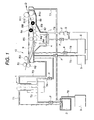
- Fig. 1 is a block diagram showing Embodiment 1-1 of the present invention.
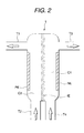
- Fig. 2 is a diagram showing an example of electrolytic cell according to the present invention.
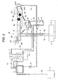
- Fig. 3 is a block diagram showing Embodiment 1-2 of the present invention.
- Fig. 4 is a block diagram showing Embodiment 1-3 of the present invention.
- Fig. 5 is a block diagram showing Embodiment 1-4 of the present invention.
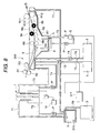
- Fig. 6 is a block diagram showing Embodiment 2-1 of the present invention.
- Fig. 7 is a block diagram showing Embodiment 2-2 of the present invention.
- Fig. 8 is a block diagram of an apparatus for carrying out the developing method of the present invention.
- Fig. 9 is a block diagram of another apparatus for carrying out the developing method of the present invention.
- the developing performance of a developing working solution can be recovered by electrolyzing a developing working solution whose alkali component has been consumed and an overflown intermediate waste solution and they can be reused in development.
- An overflown intermediate waste solution is in the first place introduced into an intermediate waste solution tank and then to an electrolytic cell.
- the intermediate waste solution introduced into the electrolytic cell passes through the positive electrode side in the electrolytic cell and introduced into the intermediate waste solution tank again.
- the developing working solution from the developing bath is introduced into the negative electrode side in the electrolytic cell and the introduced developing working solution is returned to the developing bath. That is, the intermediate waste solution introduced into the intermediate waste solution tank is circulating between the intermediate waste solution tank and the positive electrode side of the electrolytic cell and the developing working solution is circulating between the developing bath and the negative electrode side of the electrolytic cell.
- the developing working solution and the intermediate waste solution are electrolyzed in the electrolytic cell.
- the concentration of the alkali component i.e., a hydroxide ion
- the bubbles generated by the electrolysis in the electrolytic cell are flown by the above circulation to prevent the photosensitive layer component in the solution from electrodepositing and precipitating on the electrodes and the interelectrode resistance from increasing. As a result, good electrolysis can be continued. Accordingly, good recovery of the developing performance of the developing working solution can be continued.
- a developing replenisher is replenished to a developing bath and at the same time a developing working solution whose alkali component has been consumed is electrolyzed, thus the developing performance of the developing working solution can be recovered and the developing working solution can be reused in development.
- the developing working solution from the developing bath is introduced into the negative electrode side in the electrolytic cell and the introduced developing working solution is returned to the developing bath. That is, the developing working solution is circulating between the developing bath and the negative electrode side of the electrolytic cell.
- the controller judges that the developing performance of the development processing solution is lowered with the development activity detected by the detector as the criterion, an electric current is applied to the positive electrode and the negative electrode.
- the developing working solution and the developing waste solution are electrolyzed in the above-described electrolytic cell.
- the concentration of the alkali component i.e., a hydroxide ion
- a developing replenisher is replenished to the developing bath by the replenishing member and the developing performance of a developing working solution is recovered.
- the above-described replenishing member is connected to the controller to periodically control the replenishment according to at least one of the cumulative processing area of the material having a photosensitive resin composition, the cumulative operating time of the development processing apparatus, and the cumulative stopping time of the development processing apparatus, and replenishment is performed according to the instruction from the controller.
- the electrolytic cell is connected to the controller to periodically control the application of an electric current to the positive electrode and the negative electrode according to at least one of the cumulative processing area of the material having a photosensitive resin composition, the cumulative operating time of the development processing apparatus, and the cumulative stopping time of the development processing apparatus, and an electric current is applied to the positive electrode and the negative electrode according to the instruction from the controller.
- the concentration of the alkali component i.e., a hydroxide ion
- the bubbles generated by the electrolysis in the electrolytic cell are flown by the above circulation to prevent the photosensitive layer component in the solution from electrodepositing on the electrodes and the interelectrode resistance from increasing.
- good electrolysis can be continued without consuming extra electric power. Accordingly, good recovery of the developing performance of the developing working solution can be continued.
- the development processing apparatuses as described in the above items (2-1) and (2-2) may be equipped with circulating mechanism comprising introducing the overflown waste solution from the developing bath into a tank (called an intermediate waste solution tank), introducing the waste solution in the intermediate waste solution tank (called an intermediate waste solution) into the positive electrode side of the electrolytic cell, and introducing the intermediate waste solution into the intermediate waste solution tank again.
- the positive electrode side of the electrolytic cell may be equipped with a electrolysis reservoir for reserving a solution to be electrolyzed, by which the time required in solution exchange when the electrolytic cell is provided can be saved and, further, similarly to the above-described circulation of the development processing solution, the photosensitive layer component in the solution can be prevented from electrodepositing and precipitating on the electrodes and the increase of interelectrode resistance can be prevented. As a result, good electrolysis can be continued without consuming extra electric power.
- the detector detects at least one of the electric conductivity of the development processing solution, the pH value of the development processing solution, and the specific gravity and the opacity of the development processing solution, as the development activity of the development processing solution.
- the replenishing rate of a developing replenisher is smaller than the amount conventionally used.
- the amount of a replenisher By reducing the amount of a replenisher, the amount of an overflown waste solution can be reduced, as a result, the amount of a waste solution can be reduced. Since the development processing apparatus according to the present invention contrives to recover the developing performance of the development processing solution also by electrolysis, the recovering function of the developing performance cannot be reduced even when the replenishing rate of a developing replenisher is reduced.
- a developing replenisher is replenished to a developing bath and at the same time a developing working solution whose alkali component has been consumed and a waste solution are electrolyzed according to the development activity of the developing working solution detected by the first sensor, thus the developing performance of the developing working solution can be recovered and the developing working solution can be reused in development.
- the waste solution from the developing bath is in the first place introduced into an intermediate waste solution tank (this solution is called an intermediate waste solution for convenience sake) and then into an electrolytic cell.
- the intermediate waste solution introduced into the electrolytic cell is again introduced into the intermediate waste solution tank through the positive electrode side in the electrolytic cell.
- the developing working solution from the developing bath is introduced into the negative electrode side in the electrolytic cell and the introduced developing working solution is returned to the developing bath. That is, the intermediate waste solution introduced into the intermediate waste solution tank is circulating between the intermediate waste solution tank and the positive electrode side of the electrolytic cell and the developing working solution is circulating between the developing bath and the negative electrode side of the electrolytic cell.
- the developing performance of the developing solution in the developing bath can be recovered by replenishing a developing replenisher to the developing bath according to at least one of the cumulative processing area of the photosensitive material, the cumulative operating time of the development processing apparatus, and the cumulative stopping time of the development processing apparatus.
- the development activity of the intermediate waste solution overflown from the developing bath and introduced into the intermediate waste solution tank is detected by the second detector, and the replenishing rate of the developing replenisher to the developing bath is adjusted according to the detected development activity.
- the detected development activity is most preferably pH, but electric conductivity is detected first and pH may be estimated from the electric conductivity detected.
- the replenishing rate of the developing replenisher to the developing bath is reduced to reduce the amount of the overflown solution from the developing bath.
- the replenishing rate of the developing replenisher to the developing bath is increased to increase the amount of the overflown solution from the developing bath. If the amount of the solution overflown and introduced into the intermediate waste solution tank is decreased, the pH value in the intermediate waste solution tank gradually decreases by the circulation inclusive of electrolysis and becomes lower than the allowable ceiling value, in contrast with this, if the amount of the overflown solution is increased, the pH value in the intermediate waste solution tank gradually increases and becomes higher than the allowable bottom value.
- the allowable bottom value is generally such that the photosensitive layer component dissolved into the waste solution is not precipitated or deposited, and the electrolysis in the above electrolytic cell can be performed well, preferably a pH value of 12.2. If the pH value of the intermediate waste solution decreases too much, hydroxide ions in the intermediate waste solution tank become insufficient and good electrolysis cannot be performed.
- the developing performance in the developing bath can be recovered by replenishing a developing replenisher to the developing bath according to the development activity of the development processing solution detected by the first sensor.
- the development activity of the intermediate waste solution in the intermediate waste solution tank is detected by the second detector, and the application amount of an electric current is controlled according to the detected value.
- electrolysis is performed in the electrolytic cell.
- the concentration of the alkali component i.e., a hydroxide ion
- the alkali component decreases by the electrolysis.
- the preferred point of this electrolysis is capable of decreasing the pH value of intermediate waste solution while increasing the pH value of the developing working solution. According to this mechanism, the intermediate waste solution in the intermediate waste solution tank can be made harmless while recovering the developing performance of the developing working solution in the developing bath (i.e., the development processing solution).
- the final waste solution is a waste solution discharged from the intermediate waste solution tank, hence decreasing the pH value of the intermediate waste solution almost equals to decreasing the pH value of the final waste solution.
- the development activity detected by the first sensor is most preferably pH, but electric conductivity is detected first and pH may be estimated from the electric conductivity detected.
- the developing working solution and the developing waste solution are electrolyzed in the electrolytic cell according to the detected and estimated pH value.
- the detected and estimated pH value is more than the allowable ceiling value, it is preferred to increase the amount of an electric current to be applied to the positive electrode and the negative electrode.
- the pH value is less than the allowable bottom value, it is preferred to decrease the application amount of an electric current.
- the bubbles generated by the electrolysis in the electrolytic cell are flown by the above circulation to prevent the photosensitive layer component in the solution from electrodepositing and precipitating on the electrodes and the interelectrode resistance from increasing.
- good electrolysis can be continued without consuming extra electric power. Accordingly, good recovery of the developing performance of the developing working solution can be continued.
- the replenishing rate of a developing replenisher can be reduced to a smaller amount than the amount conventionally used, and the amount of a waste solution can also be reduced.
- the development processing solution for use in the development processing apparatus and developing method according to the present invention preferably has a pH value of from 9.0 to 14.0, preferably from 12.0 to 13.5.
- Conventionally well-known alkaline aqueous solutions can be used as a development processing solution for use in such development processing, e.g., inorganic alkali agents such as sodium silicate, potassium silicate, sodium tertiary phosphate, potassium tertiary phosphate, ammonium tertiary phosphate, sodium secondary phosphate, potassium secondary phosphate, ammonium secondary phosphate, sodium carbonate, potassium carbonate, ammonium carbonate, sodium hydrogencarbonate, potassium hydrogencarbonate, ammonium hydrogencarbonate, sodium borate, potassium borate, ammonium borate, sodium hydroxide, ammonium hydroxide, potassium hydroxide, and lithium hydroxide can be exemplified.
- Organic alkali agents such as monomethylamine, dimethylamine, trimethylamine, monoethylamine, diethylamine, triethylamine, monoisopropylamine, diisopropylamine, triisopropylamine, n-butylamine, monoethanolamine, diethanolamine, triethanolamine, monoisopropanolamine, diisopropanolamine, ethyleneimine, ethylenediamine, and pyridine can also be used in the present invention. These alkali agents are used alone or in combination of two or more.
- a development processing solution which exhibits a higher effect of the present invention is an aqueous solution containing alkali metal silicate and having a pH value of 12 or more.
- An aqueous solution of alkali metal silicate is capable of adjusting development property by the ratio of silicon oxide SiO 2 , which is the component of silicate, to alkaline metallic oxide M 2 O (generally represented by the molar ratio of SiO 2 /M 2 O) and the concentration.
- a development processing solution can contain various kinds of surfactants and organic solvents for the purpose of accelerating development property, dispersing development residues, and heightening the affinity of the image area of a printing plate with ink, if necessary.
- surfactants anionic, cationic, nonionic and ampholytic surfactants can be exemplified.
- surfactants may be used alone or two or more may be used in combination, preferably added to a development processing solution in an amount of from 0.001 to 10 wt%, more preferably from 0.01 to 5 wt%.
- An organic solvent may be added to a development processing solution, if necessary.
- An organic solvent having a solubility in water of 10 wt% or less, preferably 5 wt% or less is preferably used, e.g., 1-phenylethanol, 2-phenylethanol, 3-phenyl-1-propanol, 4-phenyl-1-butanol, 4-phenyl-2-butanol, 2-phenyl-1-butanol, 2-phenoxyethanol, 2-benzyloxyethanol, o-methoxybenzyl alcohol, m-methoxybenzyl alcohol, p-methoxybenzyl alcohol, benzyl alcohol, cyclohexanol, 2-methylcyclohexanol, 3-methylcyclohexanol, 4-methylcyclohexanol, N-phenylethanolamine or N-phenyldiethanolamine can be exemplified as such an organic solvent.
- the content of an organic solvent is from 0.1 to 5 wt% based on the total weight of the solution.
- the use amount of an organic solvent intimately relates to the use amount of a surfactant. It is preferred to increase the amount of a surfactant as the amount of an organic solvent is increased. This is due to the fact that if the amount of a surfactant is small and the amount of an organic solvent is large, the organic solvent does not dissolve completely and good development property cannot be ensured.
- a development processing solution may further contain an antiseptic, a coloring agent, a thickener, a defoaming agent and a water softener, if necessary.
- water softeners include, e.g., polyphosphoric acid, and sodium salt, potassium salt and ammonium salt thereof, aminopolycarboxylic acid such as ethylenediaminetetraacetic acid, diethylenetriaminepentaacetic acid, triethylenetetraminehexaacetic acid, hydroxyethylethylenediaminetriacetic acid, nitrilotriacetic acid, 1,2-diaminocyclohexanetetraacetic acid, and 1,3-diamino-2-propanoltetraacetic acid, and sodium salt, potassium salt and ammonium salt thereof, aminotri-(methylenephosphonic acid), ethylenediaminetetra(methylenephosphonic acid), diethylenetriaminepenta (methylenephosphonic acid), triethylenetetraminehexa (methylenephosphonic
- the proper addition amount of these water softeners varies according to their chelating ability and the hardness and the amount of the hard water to be used but the general amount is preferably from 0.01 to 5 wt%, more preferably from 0.01 to 0.5 wt%, based on the development processing solution to be used. If the addition amount is less than this range, the desired object cannot be achieved, while when the amount is larger than this range, an image area gets an adverse influence such as decoloration.
- a particularly preferred material having a photosensitive resin composition to which the present invention can be applied is a photosensitive material for lithographic printing, and a PS plate having a positive photosensitive resin composition is preferred above all.
- a preferred sensitizer is an o-quinonediazide compound.
- a compound having at least one o-quinonediazide group and whose solubility in an alkaline aqueous solution increases by irradiation with an active light is preferably used as the o-quinonediazide compound.
- the positive photosensitive resin composition other than the above o-quinonediazides compounds which are water-insoluble but alkali-soluble and the alkali-soluble group of which is protected with an acid-decomposable group and used in combination with a light-acid generating agent can be used as the chemically amplified photosensitive resin compositions.
- Chemically amplified photosensitive resin compositions are used as the materials for lithographic printing, integrated circuits and photoresists for other high definition microfabrication, and the development is performed by making use of the alkali solubility of an exposed area.
- Well-known light-acid generating agents can be used as the light-acid generating agent in chemically amplified photosensitive resin compositions.
- the light-acid generating agent compounds such as a photo-initiator of photo-cationic polymerization, a photo-initiator of photo-radical polymerization, a photo-decoloring agent of dyes, a discoloring agent, and well-known compounds which generate acid by the irradiation with light for use in microresists, and mixtures of these compounds can be used arbitrarily.
- compounds which are water-insoluble but alkali-soluble and the alkali-soluble group of which is protected with an acid-decomposable group used in combination with a light-acid generating agent in chemically amplified photosensitive resin compositions are the compounds having a -C-O-C- or -C-O-Si- bond, and the following examples can be exemplified.
- alkali-soluble resins e.g., a phenol-formaldehyde resin, a cresol-formaldehyde resin, a phenol-cresol-formaldehyde co-condensation resin, a phenol-modified xylene resin, polyhydroxystyrene, polyhalide hydroxystyrene, an N-(4-hydroxyphenyl) methacrylamide copolymer, a hydroquinone monomethacrylate copolymer, the sulfonylimide polymers disclosed in JP-A-7-28244, and the polymers containing a carboxyl group disclosed in JP-A-7-36184 can be exemplified.
- alkali-soluble resins e.g., a phenol-formaldehyde resin, a cresol-formaldehyde resin, a phenol-cresol-formaldehyde co-condensation resin, a phenol-modified xy
- alkali-soluble high molecular weight compounds such as the acrylate resins containing a phenolic hydroxyl group disclosed in JP-A-51-34711, the acrylate resins containing a sulfonamido group disclosed in JP-A-2-866, urethane resins, etc., can also be used.
- These alkali-soluble high molecular weight compounds have a weight average molecular weight of from 500 to 20,000 and a number average molecular weight of from 200 to 60,000.
- These alkali-soluble high molecular weight compounds may be used alone or two or more of them may be used in combination. They are used in addition amount of 80 wt% or less based on the total composition.
- a material having a photopolymerizable photosensitive resin composition which is one of the materials having a photosensitive resin composition for use in the present invention, will be described in the next place.
- a photopolymerizable photosensitive resin composition for use in the present invention is a compound containing an addition polymerizable ethylenically double bond as the main component, a photopolymerization initiator, etc., and a compound such as a thermal polymerization inhibitor, etc., may be added, if necessary.
- a compound containing an addition polymerizable ethylenically double bond can be arbitrarily selected from the compounds having at least one, preferably two or more, terminally ethylenically unsaturated bond, e.g., those assuming the chemical forms of a monomer and a prepolymer, i.e., a dimer, a trimer and an oligomer, or mixtures of them, and copolymers of them.
- esters of unsaturated carboxylic acid e.g., acrylic acid, methacrylic acid, itaconic acid, crotonic acid, isocrotonic acid, maleic acid, etc.
- aliphatic polyhydric alcohol e.g., 1,3-butanediol
- amides of unsaturated carboxylic acid and an aliphatic polyvalent amine compound can be exemplified.
- photopolymerization initiators contained in the photopolymerizable photosensitive resin compositions for use in the present invention various photopolymerization initiators well-known by patents and literature can be arbitrarily used alone or in combination of two or more according to the wavelengths of the light sources to be used.
- benzyl, benzoin ether, Michler's ketone, anthraquinone, thioxanthone, acridine, phenazine, benzophenone, etc. are widely used.
- the present invention can be used in a positive PS plate using the above-described quinonediazide or a compound having an alkali-soluble group protected with an acid-decomposable group, and a negative PS plate using a photopolymerization system. Besides the above, the present invention can also be applied to the following materials of a lithographic printing plate, printed wiring and a resist for forming an integrated circuit.
- the coating amount (a solid content) of the image-forming layer obtained after coating and drying differs according to use purpose, but the coating amount in a generally used lithographic printing plate precursor is preferably from 0.5 to 5.0 g/m 2 , more preferably from 0.5 to 1.5 g/m 2 .
- the layer thickness is generally from 0.01 to 100 ⁇ m, preferably from 0.1 to 10 ⁇ m, and more preferably from 0.3 to 1 ⁇ m.
- Development processing apparatus 10 shown in Fig. 1 is an apparatus for developing a PS plate for forming a lithographic printing plate according to Embodiment 1-1 of the present invention.
- Development processing apparatus 10 is equipped with developing bath 4, and developing bath 4 is filled with development processing solution L.
- PS plate 9 after exposure is sent in developing bath 4.
- PS plate 9 sent in is transported in developing bath 4 by means of guide 7 and rollers R1 to R12, and development processed by being slid by means of brushes 8a and 8b with passing through generally the path shown by arrow D. Thereafter, PS plate 9 is sent in the manufacturing step of the next stage.
- Piping T9 is installed at the bottom near the central part of developing bath 4, and the discharge from the spray provided at the outlet of the piping forked into two branches assists the stirring of development processing solution L. More stable development can be performed by this stirring.
- Filter F and electric conductivity sensor S are provided at intermediate portions of piping T9 to filtrate the impurities in development processing solution L and measure the electric conductivity of development processing solution L respectively
- a developing replenisher is supplied to developing bath 4 for recovering the developing performance.
- the replenishing rate is determined by the electric conductivity of development processing solution L measured by electric conductivity sensor S.
- a developing replenisher from developing replenisher tank 5 through piping T5 and, at the same time, a dilution water from dilution water tank 6 through piping T6.
- Pumps P are provided at an intermediate portion of each of piping T5 and piping T6, and a developing replenisher and a dilution water are supplied to developing bath 4 via pumps P.
- pump P in this embodiment is a bellows pump but other pumps, e.g., a magnet pump, may be used.
- the developing replenisher and the dilution water introduced into developing bath 4 are mixed in developing bath 4 to make development processing solution L, but development processing solution L may be introduced into developing bath 4 after being mixed.
- Development processing solution L overflown from developing bath 4 by the replenishment of a replenisher is introduced into intermediate waste solution tank 2 through piping T7.
- the solution passed through piping T7 is called an intermediate waste solution for convenience sake.
- a part of development processing solution L is introduced into electrolytic cell 1 through piping T4 on the other hand.
- the solution passed through piping T4 is called a developing working solution for convenience sake.
- Piping T8 besides T1 and T2 is connected to intermediate waste solution tank 2.
- Piping T8 is connected to waste solution tank 3, and when the intermediate waste solution in intermediate waste solution tank 2 exceeds a definite amount, the intermediate waste solution is introduced into waste solution tank 3 through piping T8.
- these solutions are introduced into electrolytic cell 1 to be subjected to electrolysis properly, thus the negative electric charge (electron) in the intermediate waste solution is transferred into the developing working solution with reducing the hydroxide ions in the intermediate waste solution and increasing the hydroxide ions in the developing working solution, to thereby lower the pH value of the intermediate waste solution and increase the pH value of the developing working solution. That is, the alkalinization of the developing working solution introduced into electrolytic cell 1 progresses and, similarly, the neutralization of the intermediate waste solution progresses. Accordingly, the developing performance of the developing working solution is recovered by electrolysis. The mechanism of the electrolysis is described below together with explanations of electrolytic cell 1.
- Electrolytic cell 1 comprises positive electrode chamber C2 communicating with intermediate waste solution tank 2 via pipings T1 and T2 and negative electrode chamber C1 communicating with developing bath 4 via pipings T3 and T4. Negative electrode chamber C1 and positive electrode chamber C2 are partitioned by ion exchange membrane IE. Electrolytic cell 1 is further equipped with negative electrode NE arranged on the inner surface of the outside wall of negative electrode chamber C1 and positive electrode PE arranged on the inner surface of the outside wall of positive electrode chamber 2. Direct current voltage is impressed between positive electrode PE and negative electrode NE. An intermediate waste solution is introduced from piping T2 and a developing working solution is introduced from piping T4.
- the pH value of the developing working solution becomes large by electrolysis, thus the developing performance is recovered.
- the developing working solution is again introduced into developing bath 4 via piping T3 and the intermediate waste solution is again introduced into intermediate waste solution tank 2 via piping T1.
- the developing working solution circulates a first route from developing bath 4 through piping T4, electrolytic cell 1, piping T3, and again to developing bath 4.
- the intermediate waste solution circulates a second route from intermediate waste solution tank 2 through piping T2, electrolytic cell 1, piping T1, and again to intermediate waste solution tank 2.
- the circulations are always done while development processing apparatus 10 is operated.
- the alkali component in developing bath 4 becomes difficult to reduce as the developing working solution is subjected to electrolysis treatment with circulating between developing bath 4 and electrolytic cell 1. Since the replenishing rate of a developing replenisher increases as the alkali component in developing bath 4 becomes more liable to reduce, the replenishing rate of a developing replenisher can be relatively reduced by carrying out the present invention. This means a reduction of the overflow from developing bath 4, which results in a reduction of an intermediate waste solution, furthermore, a reduction of a final waste solution.
- the functions of circulating a development processing solution and an intermediate waste solution through the electrolytic cell are as follows. First, since the solutions are always circulating, the flowing in electrolytic cell 1 becomes good, and hydrogen and oxygen bubbles generated by electrolysis flow without stagnating on the electrodes. Secondly, since also the solutions are always circulating, the flowing in electrolytic cell 1 becomes good, and electrodeposition and precipitation of the composition in a photosensitive layer on the electrodes are difficult to occur. The increase of the interelectrode resistance can be inhibited by these functions. Accordingly, good electrolysis can be performed continuously.
- Fig. 3 shows Embodiment 1-2 of the present invention.
- the action of piping T9 in Embodiment 1-1 is performed by the circulation from piping T4 to piping T3.
- Piping T4 communicates with the bottom near the central part of developing bath 4 and negative electrode chamber C1 of electrolytic cell 1, and filter F and electric conductivity sensor S are provided at intermediate portions of piping T4.
- piping T3 communicating with negative electrode chamber C1 of electrolytic cell 1 and developing bath 4 assists the stirring of development processing solution L by the opening of the outlet of the piping forked into two branches. More stable development can be performed by this stirring. Accordingly, piping T9 in the embodiment shown in Fig. 1 can be omitted and the structure of the apparatus can be simplified.
- Fig. 4 shows Embodiment 1-3 of the present invention.
- the difference between Embodiment 1-1 and Embodiment 1-3 resides in heights of setting up of intermediate waste solution tank 2 and piping T8.
- the places of installation of intermediate waste solution tank 2 and piping T8 are set so that the liquid level of the intermediate waste solution in intermediate waste solution tank 2 becomes equal to the liquid level of the development processing solution in a developing bath, and the overflow of the intermediate waste solution in intermediate waste solution tank 2 flows into piping T8.
- the solution in electrolytic cell 1 can be prevented from flowing into intermediate waste solution tank 2 or developing bath 4 one-sidedly even if ion exchange membrane IE should be broken, and since the hydrostatic pressures between intermediate waste solution tank 2 and developing bath 4 are equal during stoppage of the apparatus (during stoppage of pump P), the fluctuation of the liquid level can be prevented.
- Fig. 5 shows Embodiment 1-4 of the present invention. This is the combination of Embodiments 1-2 and 1-3, and this embodiment has preferable functions of both embodiments.
- Piping T4 communicates with the bottom near the central part of developing bath 4 and negative electrode chamber C1 of electrolytic cell 1, and filter F and electric conductivity sensor S are provided at intermediate portions of piping T4.
- piping T3 communicating with negative electrode chamber C1 of electrolytic cell 1 and developing bath 4 assists the stirring of development processing solution L by the discharge from the spray provided at the outlet of the piping forked into two branches. More stable development can be performed by this stirring. Accordingly, piping T9 in the embodiment shown in Fig. 1 can be omitted and the structure of the apparatus can be simplified.
- intermediate waste solution tank 2 and piping T8 are set so that the liquid level of the intermediate waste solution in intermediate waste solution tank 2 becomes equal to the liquid level of the development processing solution in a developing bath, and the solution in electrolytic cell 1 can be prevented from flowing into intermediate waste solution tank 2 or developing bath 4 one-sidedly even if ion exchange membrane IE should be broken. Since the hydrostatic pressures between intermediate waste solution tank 2 and developing bath 4 are equal during stoppage of the apparatus (during stoppage of pump P), the fluctuation of the liquid level can be prevented.
- the development processing apparatus comprises: an intermediate waste solution tank to which the overflown waste solution from the developing bath is introduced; an electrolytic cell for electrolyzing the developing working solution introduced from the developing bath and the overflown waste solution introduced from the intermediate waste solution tank; and circulating mechanism comprising a first route for circulating the developing working solution between the negative electrode side of the electrolytic cell and the developing bath, and a second route for circulating the overflown waste solution between the positive electrode side of the electrolytic cell and the intermediate waste solution tank.
- the amounts of a developing replenisher and a waste solution can be reduced, the electrodeposition of the components of a photosensitive layer on the electrodes can be inhibited due to the circulation of the solution, and bubbles generated by electrolysis can flow without stagnating, as a result, good electrolysis can be continued in an electrolytic cell. Therefore, the amount of a waste solution can be reduced with maintaining developing performance in the developing bath.
- Development processing apparatus 210 shown in Fig. 6, which is Embodiment 2-1 of the present invention, is an apparatus for developing a PS plate for forming a lithographic printing plate.
- conductance sensor S corresponds to a detector for detecting the development activity of the development processing solution.
- a replenishing member is provided for replenishing a developing replenisher to developing bath 4.
- a developing replenisher from developing replenisher tank 5 through piping T5 and, at the same time, a dilution water from dilution water tank 6 through piping T6.
- the amount of the developing replenisher to be replenished may be smaller than the amount conventionally replenished for the reason described below.
- Pumps 13 and 14 are provided at an intermediate portion of each of piping T5 and piping T6, and these pumps function as the above-described replenishing members. In Fig. 6 (and also in Fig. 7), the arrows in pumps 13, 14 and other pumps P show the direction of the solutions flowing in these pumps.
- pumps 13 and 14 are connected to controller 212, the replenishment of a developing replenisher by means of pumps 13 and 14 is controlled by the instruction periodically given by controller 212 according to at least one of the cumulative processing area of PS plate 9, the cumulative operating time of development processing apparatus 210, and the cumulative stopping time of development processing apparatus 210.
- pumps 13, 14 and P in this embodiment are bellows pumps and pump p1 is a magnet pump, but other pumps may be used.
- the developing replenisher and the dilution water introduced into developing bath 4 are mixed in developing bath 4 to make development processing solution L, but development processing solution L may be introduced into developing bath 4 after being mixed.
- Electrolysis is performed in electrolytic cell 1 in the same manner as in Embodiment 1-1, but this electrolysis is controlled by controller 211 connected to electric conductivity sensor S according to the value detected by electric conductivity sensor S. For instance, when the detected value inputted in controller 211 is smaller than the threshold value prescribed in controller 211 in advance, an electric current is applied to electrolytic cell 1 to perform electrolysis, and when the detected value is larger than the threshold value, electrolysis is not performed. Direct current voltage is impressed between positive electrode PE and negative electrode NE based on the instruction from controller 211.
- the development processing solution is replenished according to at least one of the cumulative processing area of PS plate 9, the cumulative operating time of development processing apparatus 210, and the cumulative stopping time of development processing apparatus 210, and the replenishing rate of a developing replenisher is set smaller than the amount conventionally used, and the shortage of the alkali component in developing bath 4 is compensated for by electrolysis, hence the use amount of a developing replenisher can be reduced according to the present invention.
- the functions of circulating a development processing solution and an intermediate waste solution through electrolytic cell 1 are as follows. First, since the solutions are always circulating, the flowing in electrolytic cell 1 becomes good, and hydrogen and oxygen bubbles generated by electrolysis flow without stagnating on the electrodes. Secondly, since also the solutions are always circulating, the flowing in electrolytic cell 1 becomes good, and precipitation of the composition in a photosensitive layer on the electrodes is difficult to occur. The increase of the interelectrode resistance can be inhibited by these functions. Accordingly, good electrolysis can be performed continuously.
- Embodiment 2-2 of the present invention is an apparatus of developing a PS plate for forming a printing plate.
- the differences between this embodiment and Embodiment 2-1 are that pumps 13 and 14 (replenishing members) are controlled by controller 212 and electrolytic cell 1 by controller 211. Other points are almost the same with those in Embodiment 2-1.
- a developing replenisher is replenished to developing bath 4.
- the replenishment is controlled by controller 211 connected to electric conductivity sensor S according to the value detected by electric conductivity sensor S. For instance, when the detected value inputted in controller 211 is smaller than the threshold value prescribed in controller 211 in advance, replenishment of a developing replenisher is performed by means of driving pumps 13 and 14 provided at pipings T5 and T6 of undiluted developing replenisher tank 5 and dilution water tank 6, respectively, and when the detected value is larger than the threshold value, replenishment is not performed.
- a developing replenisher from developing replenisher tank 5 through piping T5 and, at the same time, a dilution water from dilution water tank 6 through piping T6.
- Electrolysis is performed in electrolytic cell 1 in the same manner as in Embodiment 2-1 and this electrolysis is controlled by controller 212 connected to electrolytic cell 1. Therefore, the electrolysis is controlled by the application of an electric current according to at least one of the cumulative processing area of PS plate 9, the cumulative operating time of development processing apparatus 220, and the cumulative stopping time of development processing apparatus 220.
- the alkali component in developing bath 4 becomes difficult to reduce as the developing working solution is properly subjected to electrolysis treatment with circulating between developing bath 4 and electrolytic cell 1. Since the replenishing rate of a developing replenisher increases as the alkali component in developing bath 4 becomes more liable to reduce, the replenishing rate of a developing replenisher can be relatively reduced by carrying out the present invention. This means a reduction of the overflow from developing bath 4, which results in a reduction of an intermediate waste solution, furthermore, a reduction of a final waste solution.
- the development processing apparatus comprises: a replenishing member to replenish a developing replenisher to a developing bath according to at least one of the cumulative processing area of a photosensitive material, the cumulative operating time of the development processing apparatus, and the cumulative stopping time of the development processing apparatus; a detector to detect the development activity of the development processing solution in the developing bath; and an electrolytic cell for electrolyzing the developing working solution introduced from the developing bath, wherein the electrolytic cell is partitioned by a bulkhead between the negative electrode and the positive electrode, and contains circulating mechanism for circulating the developing working solution between the negative electrode side of the electrolytic cell and the developing bath, and is connected to a controller to control the application of an electric current to the positive electrode and the negative electrode according to the development activity of the development processing solution detected by the detector.
- the amount of the developing replenisher replenished according to at least one of the cumulative processing area of the photosensitive material, the cumulative operating time of the development processing apparatus, and the cumulative stopping time of the development processing apparatus can be set smaller than the amount conventionally used, and the shortage of an alkali component is compensated for by properly electrolyzing the overflown developing waste solution and the developing working solution in the electrolytic cell, and the developing working solution is then returned to the developing bath.
- the final waste solution can be reduced. Since the solutions are always circulating in the electrolytic cell, binders, etc., can be prevented from electrodepositing and precipitating on the electrodes, bubbles can be prevented from stagnating'on the electrodes, and the interelectrode resistance can be prevented from increasing. As a result, good electrolysis can be continued without consuming extra electric power.
- the development processing apparatus comprises: a replenishing member to replenish a developing replenisher to the developing bath; a detector to detect the development activity of the development processing solution in the developing bath; and an electrolytic cell for electrolyzing the developing working solution introduced from the developing bath, wherein the electrolytic cell is partitioned by a bulkhead between the negative electrode and the positive electrode, contains a circulating mechanism for circulating the developing working solution between the negative electrode side of the electrolytic cell and the developing bath, and is connected to a controller to control the application of an electric current to the positive electrode and the negative electrode according to the development activity of the development processing solution detected by the detector, and further, the replenishing member is connected to a controller to control the replenishment to the developing bath according to the development activity of the development processing solution detected by the detector.
- development processing can be performed with properly replenishing a smaller amount of a developing replenisher than the amount conventionally used by properly electrolyzing the overflown developing waste solution and the developing working solution in the electrolytic cell, and returning the developing working solution to the developing bath.
- the final waste solution can be reduced. Since the solutions are always circulating in the electrolytic cell, binders, etc., can be prevented from electrodepositing and precipitating on the electrodes, bubbles can be prevented from stagnating on the electrodes, and the interelectrode resistance can be prevented from increasing. As a result, good electrolysis can be continued without consuming extra electric power.
- Filter F and first sensor S are provided at intermediate portions of piping T9 to filtrate the impurities in development processing solution L and measure the electric conductivity of development processing solution L respectively.
- a replenishing member is provided for replenishing a developing replenisher to developing bath 4.
- a developing replenisher from developing replenisher tank 5 through piping T5 and, at the same time, a dilution water from dilution water tank 6 through piping T6.
- the amount of the developing replenisher to be replenished may be smaller than the amount conventionally replenished for the reason described below.
- Pumps 13 and 14 are provided at an intermediate portion of each of piping T5 and piping T6, and these pumps function as the above-described replenishing members. In Fig. 8 (and also in Fig. 9), the arrows in pumps 13, 14 and P and other pumps P show the direction of the solutions flowing in these pumps.
- pumps 13 and 14 are connected to controller 311, the replenishment of a developing replenisher by means of pumps 13 and 14 is controlled by the instruction periodically given by controller 311 according to at least one of the cumulative processing area of PS plate 9, the cumulative operating time of development processing apparatus 310, and the cumulative stopping time of development processing apparatus 310.
- pumps 13, 14 and P in this embodiment are bellows pumps and pump p1 is a magnet pump, but other pumps may be used.
- the developing replenisher and the dilution water introduced into developing bath 4 are mixed in developing bath 4 to make development processing solution L, but development processing solution L may be introduced into developing bath 4 after being mixed.
- Electrolysis is performed in electrolytic cell 1 in the same manner as in Embodiment 2-1.
- Direct current voltage is impressed between positive electrode PE and negative electrode NE based on the instruction from controller 312.
- the electric conductivity detected by first sensor 1 is inputted in controller 312, and the application of an electric current to electrolytic cell 1 is controlled according to the electric conductivity. For example, when the inputted electric conductivity is less than the proper electric conductivity, application of an electric current is performed.
- An intermediate waste solution is introduced from piping T2 and a developing working solution is introduced from piping T4.
- the development processing solution is replenished according to at least one of the cumulative processing area of PS plate 9, the cumulative operating time of development processing apparatus 310, and the cumulative stopping time of development processing apparatus 310, and the replenishing rate of a developing replenisher is set smaller than the amount conventionally used, and the shortage of the alkali component in developing bath 4 is compensated for by electrolysis, hence the use amount of a developing replenisher can be relatively reduced according to the present invention.
- the functions of circulating a development processing solution and an intermediate waste solution through electrolytic cell 1 are as follows. First, since the solutions are always circulating, the flowing in electrolytic cell 1 becomes good, and hydrogen and oxygen bubbles generated by electrolysis flow without stagnating on electrodes PE and NE. Secondly, since also the solutions are always circulating, the flowing in electrolytic cell 1 becomes good, and electrodeposition and precipitation of the composition in a photosensitive layer on electrodes PE and NE is difficult to occur. The increase of the interelectrode resistance can be inhibited by these functions. Accordingly, good electrolysis can be performed continuously.
- development processing apparatus 310 detects the development activity of the intermediate waste solution in intermediate waste solution tank 2 by second sensor 315 and adjusts the replenishing rate of the developing replenisher to developing bath 4 according to the development activity detected.
- second sensor 315 is a pH sensor but second sensor 315 may be, e.g., an electric conductivity sensor. In such a case, another means to estimate a pH value from the detected electric conductivity is provided.
- controller 311 controls the replenishing rate of the developing replenisher according to at least one of the cumulative processing area of PS plate 9, the cumulative operating time of development processing apparatus 310, and the cumulative stopping time of development processing apparatus 310 based on the decision value.
- controller 311 actuates pumps 13 and 14 to reduce the replenishing rate of the developing replenisher to be replenished to developing bath 4 to thereby reduce the overflown solution amount from developing bath 4.
- controller 311 While when the decision value is lower than the allowable bottom value, controller 311 actuates pumps 13 and 14 to increase the replenishing rate of the developing replenisher to be replenished to developing bath 4 to thereby increase the overflown solution amount from developing bath 4. If the amount of the solution overflown and introduced into the intermediate waste solution tank 2 is decreased, the pH value in the intermediate waste solution tank 2 gradually decreases by the circulation inclusive of electrolysis and becomes lower than the allowable ceiling value, in contrast with this, if the amount of the overflown solution is increased, the pH value in intermediate waste solution tank 2 gradually increases and becomes higher than the allowable bottom value.
- the allowable bottom value is generally such that the photosensitive layer component dissolved into the waste solution is not precipitated or deposited, and the electrolysis in electrolytic cell 1 can be performed well, in this embodiment it is a pH value of 12.2. If the pH value of the intermediate waste solution decreases too much, hydroxide ions in the intermediate waste solution tank become insufficient and good electrolysis cannot be performed, therefore, it is effective to set this allowable bottom value.
- the replenishing rate of a developing replenisher replenished in development processing apparatus 310 is preferably smaller than the amount conventionally used. By reducing the amount of a replenisher, the amount of an overflown waste solution can be reduced, as a result, the amount of a waste solution can be reduced. Since the development processing apparatus according to the present invention contrives to recover the developing performance of the development processing solution also by electrolysis, the recovering function of the developing performance cannot be reduced even when the replenishing rate of a developing replenisher is reduced.
- controller 311 does not control the actuation of pumps 13 and 14 but controls the application amount of an electric current to electrolytic cell 1 and that controller 312 controls the actuation of pumps 13 and 14.
- Other points are almost the same with those in Embodiment 3-1.
- development processing apparatus 320 the application of an electric current to the positive electrode and the negative electrode in electrolytic cell 1 is performed by controller 311 according to at least one of the cumulative processing area of PS plate 9, the cumulative operating time of development processing apparatus 20, and the cumulative stopping time of development processing apparatus 20, by which the developing performance in developing bath 4 is recovered.
- the developing replenisher is replenished by the instruction from controller 312 sent according to the development activity in developing bath 4 detected by first sensor S.
- the development activity of the intermediate waste solution in intermediate waste solution tank 2 is detected by second sensor 15 for the intermediate waste solution, and the application of an electric current to the positive electrode and the negative electrode in electrolytic cell 1 is performed according to the development activity.
- electrolysis is performed in electrolytic cell 1.
- the concentration of the alkali component i.e., a hydroxide ion
- the alkali component decreases by the electrolysis. That is, the pH value of intermediate waste solution can be decreased while increasing the pH value of the developing working solution.
- the intermediate waste solution in the intermediate waste solution tank 2 can be made harmless while recovering the developing performance of the developing working solution in developing bath 4 (i.e., development processing solution L).
- the final waste solution is a waste solution discharged from intermediate waste solution tank 2, hence decreasing the pH value of the intermediate waste solution almost equals to decreasing the pH value of the final waste solution.
- Embodiment 3-2 when the decision value is more than the allowable ceiling value, the application amount of an electric current to the positive electrode and the negative electrode is increased.
- the allowable bottom value is generally such that the photosensitive layer component dissolved into the waste solution is not precipitated or deposited, and the electrolysis in electrolytic cell 1 can be performed well, in this embodiment it is a pH value of 12.2. If the pH value of the intermediate waste solution decreases too much, hydroxide ions in the intermediate waste solution tank become insufficient and good electrolysis cannot be performed, therefore, it is effective to set this allowable bottom value.
- the replenishing rate of the developing replenisher replenished in development processing apparatus 320 is preferably smaller than the amount conventionally used.
- the amount of a replenisher By reducing the amount of a replenisher, the amount of an overflown waste solution can be reduced, as a result, the amount of a waste solution can be reduced. Since the development processing apparatus according to the present invention contrives to recover the developing performance of the development processing solution also by electrolysis, the recovering function of the developing performance cannot be reduced even when the replenishing rate of a developing replenisher is reduced.
- allowable ceiling value and allowable bottom value may be de determined according to the decree.
- the amount of a waste solution can be reduced with maintaining the development activity of a development processing solution, wherein the development activity of the developing solution in a developing bath is maintained by electrolytic treatment of the developing solution in the negative electrode side of an electrolytic cell, and replenishing a developing replenisher to the developing solution in the developing bath, the development activity of the developing solution in the developing bath is detected and the electrolytic treatment is performed according to the value detected, and the replenishment of the developing replenisher is performed by corresponding to the processing area of the photosensitive material and the operating time of the development processing apparatus, and the correspondence is adjusted according to the physical properties of the developing waste solution introduced into the positive electrode side of the electrolytic cell.
- the amount of a waste solution can be reduced with maintaining the development activity of a development processing solution, wherein the development activity of the developing solution is maintained by electrolytic treatment of the developing solution in the negative electrode side of an electrolytic cell, and replenishing a developing replenisher to the developing solution in the developing bath, the development activity of the developing solution in the developing bath is detected and the replenishment of the developing replenisher is performed according to the value detected, and the electrolytic treatment is performed by corresponding to the processing area of the photosensitive material and the operating time of the development processing apparatus, and the correspondence is adjusted according to the physical properties of the developing waste solution introduced into the positive electrode side of the electrolytic cell.
Landscapes
- Engineering & Computer Science (AREA)
- Environmental & Geological Engineering (AREA)
- Physics & Mathematics (AREA)
- General Physics & Mathematics (AREA)
- Photosensitive Polymer And Photoresist Processing (AREA)
- Water Treatment By Electricity Or Magnetism (AREA)
Applications Claiming Priority (6)
| Application Number | Priority Date | Filing Date | Title |
|---|---|---|---|
| JP34890799 | 1999-12-08 | ||
| JP34890799A JP3925892B2 (ja) | 1999-12-08 | 1999-12-08 | 感光性樹脂組成物を有する材料の現像処理装置 |
| JP35325499 | 1999-12-13 | ||
| JP35325499A JP3901413B2 (ja) | 1999-12-13 | 1999-12-13 | 感光材料の現像処理装置 |
| JP2000043135 | 2000-02-21 | ||
| JP2000043135A JP2001235876A (ja) | 2000-02-21 | 2000-02-21 | 感光材料の現像方法 |
Publications (2)
| Publication Number | Publication Date |
|---|---|
| EP1117007A2 true EP1117007A2 (fr) | 2001-07-18 |
| EP1117007A3 EP1117007A3 (fr) | 2002-08-21 |
Family
ID=27341297
Family Applications (1)
| Application Number | Title | Priority Date | Filing Date |
|---|---|---|---|
| EP00126477A Withdrawn EP1117007A3 (fr) | 1999-12-08 | 2000-12-07 | Appareil et procédé de développement pour matériaux photosensibles |
Country Status (1)
| Country | Link |
|---|---|
| EP (1) | EP1117007A3 (fr) |
Cited By (4)
| Publication number | Priority date | Publication date | Assignee | Title |
|---|---|---|---|---|
| EP1522897A3 (fr) * | 2003-10-08 | 2005-11-02 | Kodak Polychrome Graphics, LLC | Système de formation d'images |
| US7379783B2 (en) | 2004-05-06 | 2008-05-27 | Smp Logic Systems Llc | Manufacturing execution system for validation, quality and risk assessment and monitoring of pharmaceutical manufacturing processes |
| US7392107B2 (en) | 2004-05-06 | 2008-06-24 | Smp Logic Systems Llc | Methods of integrating computer products with pharmaceutical manufacturing hardware systems |
| EP2444846A3 (fr) * | 2010-10-20 | 2013-12-25 | E. I. du Pont de Nemours and Company | Procédé de rééquilibrage d'une solution de solvant multicomposant |
Family Cites Families (6)
| Publication number | Priority date | Publication date | Assignee | Title |
|---|---|---|---|---|
| JPS61110142A (ja) * | 1984-11-05 | 1986-05-28 | Fuji Photo Film Co Ltd | 感光性印刷版用自動現像機における現像補充液の補充方法 |
| JP2942422B2 (ja) * | 1992-09-30 | 1999-08-30 | 富士写真フイルム株式会社 | 写真処理装置および処理方法 |
| JP3360365B2 (ja) * | 1993-07-29 | 2002-12-24 | クロリンエンジニアズ株式会社 | 水酸化テトラアルキルアンモニムの再生方法 |
| FR2760840B1 (fr) * | 1997-03-11 | 1999-05-07 | Kodak Pathe | Procede de controle de l'activite d'une composition de developpement inorganique |
| EP1037116A3 (fr) * | 1999-03-18 | 2000-11-08 | Fuji Photo Film Co., Ltd. | Procédé de développement d'un précurseur de plaque d'impression lithographique et appareil de développement |
| JP2001100398A (ja) * | 1999-09-28 | 2001-04-13 | Fuji Photo Film Co Ltd | 平版印刷版の製版方法、自動現像機、及び記録媒体 |
-
2000
- 2000-12-07 EP EP00126477A patent/EP1117007A3/fr not_active Withdrawn
Cited By (17)
| Publication number | Priority date | Publication date | Assignee | Title |
|---|---|---|---|---|
| EP1522897A3 (fr) * | 2003-10-08 | 2005-11-02 | Kodak Polychrome Graphics, LLC | Système de formation d'images |
| USRE43527E1 (en) | 2004-05-06 | 2012-07-17 | Smp Logic Systems Llc | Methods, systems, and software program for validation and monitoring of pharmaceutical manufacturing processes |
| US8591811B2 (en) | 2004-05-06 | 2013-11-26 | Smp Logic Systems Llc | Monitoring acceptance criteria of pharmaceutical manufacturing processes |
| US7392107B2 (en) | 2004-05-06 | 2008-06-24 | Smp Logic Systems Llc | Methods of integrating computer products with pharmaceutical manufacturing hardware systems |
| US7428442B2 (en) | 2004-05-06 | 2008-09-23 | Smp Logic Systems | Methods of performing path analysis on pharmaceutical manufacturing systems |
| US7471991B2 (en) | 2004-05-06 | 2008-12-30 | Smp Logic Systems Llc | Methods, systems, and software program for validation and monitoring of pharmaceutical manufacturing processes |
| US7509185B2 (en) | 2004-05-06 | 2009-03-24 | Smp Logic Systems L.L.C. | Methods, systems, and software program for validation and monitoring of pharmaceutical manufacturing processes |
| US7379784B2 (en) | 2004-05-06 | 2008-05-27 | Smp Logic Systems Llc | Manufacturing execution system for validation, quality and risk assessment and monitoring of pharmaceutical manufacturing processes |
| US7799273B2 (en) | 2004-05-06 | 2010-09-21 | Smp Logic Systems Llc | Manufacturing execution system for validation, quality and risk assessment and monitoring of pharmaceutical manufacturing processes |
| US8491839B2 (en) | 2004-05-06 | 2013-07-23 | SMP Logic Systems, LLC | Manufacturing execution systems (MES) |
| US7379783B2 (en) | 2004-05-06 | 2008-05-27 | Smp Logic Systems Llc | Manufacturing execution system for validation, quality and risk assessment and monitoring of pharmaceutical manufacturing processes |
| US9304509B2 (en) | 2004-05-06 | 2016-04-05 | Smp Logic Systems Llc | Monitoring liquid mixing systems and water based systems in pharmaceutical manufacturing |
| US8660680B2 (en) | 2004-05-06 | 2014-02-25 | SMR Logic Systems LLC | Methods of monitoring acceptance criteria of pharmaceutical manufacturing processes |
| US9008815B2 (en) | 2004-05-06 | 2015-04-14 | Smp Logic Systems | Apparatus for monitoring pharmaceutical manufacturing processes |
| US9092028B2 (en) | 2004-05-06 | 2015-07-28 | Smp Logic Systems Llc | Monitoring tablet press systems and powder blending systems in pharmaceutical manufacturing |
| US9195228B2 (en) | 2004-05-06 | 2015-11-24 | Smp Logic Systems | Monitoring pharmaceutical manufacturing processes |
| EP2444846A3 (fr) * | 2010-10-20 | 2013-12-25 | E. I. du Pont de Nemours and Company | Procédé de rééquilibrage d'une solution de solvant multicomposant |
Also Published As
| Publication number | Publication date |
|---|---|
| EP1117007A3 (fr) | 2002-08-21 |
Similar Documents
| Publication | Publication Date | Title |
|---|---|---|
| US4259434A (en) | Method for developing positive acting light-sensitive planographic printing plate | |
| US6794120B2 (en) | Method of processing light sensitive planographic printing plate precursor | |
| JP5695267B2 (ja) | 製版処理廃液の濃縮方法およびリサイクル方法 | |
| EP0323836A2 (fr) | Procédé pour la fabrication de plaques d'impression lithographiques | |
| EP0405986A2 (fr) | Méthode de traitement d'une plaque lithographique présensibilisée | |
| JPH1010754A (ja) | 感光性平版印刷版の処理方法 | |
| JP3901413B2 (ja) | 感光材料の現像処理装置 | |
| JP3518632B2 (ja) | 平版印刷版の製版方法 | |
| JP3925892B2 (ja) | 感光性樹脂組成物を有する材料の現像処理装置 | |
| JP2001235876A (ja) | 感光材料の現像方法 | |
| US5278030A (en) | Developer solution comprising ethyl hexyl sulphate, a surfactant, an alkaline material and having a pH of not less than 12 | |
| JPH08278636A (ja) | 光重合性感光性平版印刷版の処理方法 | |
| JP2000267296A (ja) | 感光性樹脂組成物を有する材料の現像処理方法及び現像処理装置 | |
| JPH08123039A (ja) | 感光性平版印刷版の処理方法 | |
| EP0366321A2 (fr) | Développement de compositions photosensibles | |
| JPH0616172B2 (ja) | 現像安定性等が改良される感光性平版印刷版の処理方法 | |
| JPS6255658A (ja) | 感光性平版印刷版の処理方法 | |
| JPH04287046A (ja) | 感光性平版印刷版の処理方法 | |
| JPH0822117A (ja) | 感光性平版印刷版の処理方法及び装置並びに清浄方法 | |
| JPH11253969A (ja) | アルカリ性産業廃棄物のpH低下剤およびそれを用いたpH低下方法 | |
| JP2004004275A (ja) | 感光性平版印刷版材料の処理方法および現像液 | |
| JPH11290868A (ja) | アルカリ性産業廃棄物のpH低下剤及びそれを用いたpH低下方法 | |
| JPH09288357A (ja) | 感光性記録材料の処理方法 | |
| JPH06230582A (ja) | ポジ型感光性平版印刷版の処理方法 | |
| JPH11258823A (ja) | 感光性平版印刷版用フィニッシング液 |
Legal Events
| Date | Code | Title | Description |
|---|---|---|---|
| PUAI | Public reference made under article 153(3) epc to a published international application that has entered the european phase |
Free format text: ORIGINAL CODE: 0009012 |
|
| AK | Designated contracting states |
Kind code of ref document: A2 Designated state(s): AT BE CH CY DE DK ES FI FR GB GR IE IT LI LU MC NL PT SE TR |
|
| AX | Request for extension of the european patent |
Free format text: AL;LT;LV;MK;RO;SI |
|
| PUAL | Search report despatched |
Free format text: ORIGINAL CODE: 0009013 |
|
| AK | Designated contracting states |
Kind code of ref document: A3 Designated state(s): AT BE CH CY DE DK ES FI FR GB GR IE IT LI LU MC NL PT SE TR |
|
| AX | Request for extension of the european patent |
Free format text: AL;LT;LV;MK;RO;SI |
|
| 17P | Request for examination filed |
Effective date: 20021111 |
|
| AKX | Designation fees paid |
Designated state(s): DE GB |
|
| RAP1 | Party data changed (applicant data changed or rights of an application transferred) |
Owner name: FUJIFILM CORPORATION |
|
| 17Q | First examination report despatched |
Effective date: 20050811 |
|
| STAA | Information on the status of an ep patent application or granted ep patent |
Free format text: STATUS: THE APPLICATION IS DEEMED TO BE WITHDRAWN |
|
| 18D | Application deemed to be withdrawn |
Effective date: 20090820 |