EP1122973A2 - Digitaler Pulsbreiten-Modulationsgenerator - Google Patents
Digitaler Pulsbreiten-Modulationsgenerator Download PDFInfo
- Publication number
- EP1122973A2 EP1122973A2 EP01108918A EP01108918A EP1122973A2 EP 1122973 A2 EP1122973 A2 EP 1122973A2 EP 01108918 A EP01108918 A EP 01108918A EP 01108918 A EP01108918 A EP 01108918A EP 1122973 A2 EP1122973 A2 EP 1122973A2
- Authority
- EP
- European Patent Office
- Prior art keywords
- bit
- input
- output
- digital
- unary
- Prior art date
- Legal status (The legal status is an assumption and is not a legal conclusion. Google has not performed a legal analysis and makes no representation as to the accuracy of the status listed.)
- Granted
Links
Images


Classifications
-
- H—ELECTRICITY
- H03—ELECTRONIC CIRCUITRY
- H03K—PULSE TECHNIQUE
- H03K7/00—Modulating pulses with a continuously-variable modulating signal
- H03K7/08—Duration or width modulation ; Duty cycle modulation
-
- H—ELECTRICITY
- H04—ELECTRIC COMMUNICATION TECHNIQUE
- H04R—LOUDSPEAKERS, MICROPHONES, GRAMOPHONE PICK-UPS OR LIKE ACOUSTIC ELECTROMECHANICAL TRANSDUCERS; ELECTRIC HEARING AIDS; PUBLIC ADDRESS SYSTEMS
- H04R1/00—Details of transducers, loudspeakers or microphones
- H04R1/005—Details of transducers, loudspeakers or microphones using digitally weighted transducing elements
-
- H—ELECTRICITY
- H04—ELECTRIC COMMUNICATION TECHNIQUE
- H04R—LOUDSPEAKERS, MICROPHONES, GRAMOPHONE PICK-UPS OR LIKE ACOUSTIC ELECTROMECHANICAL TRANSDUCERS; ELECTRIC HEARING AIDS; PUBLIC ADDRESS SYSTEMS
- H04R1/00—Details of transducers, loudspeakers or microphones
- H04R1/20—Arrangements for obtaining desired frequency or directional characteristics
- H04R1/22—Arrangements for obtaining desired frequency or directional characteristics for obtaining desired frequency characteristic only
- H04R1/227—Arrangements for obtaining desired frequency or directional characteristics for obtaining desired frequency characteristic only using transducers reproducing the same frequency band
-
- H—ELECTRICITY
- H04—ELECTRIC COMMUNICATION TECHNIQUE
- H04R—LOUDSPEAKERS, MICROPHONES, GRAMOPHONE PICK-UPS OR LIKE ACOUSTIC ELECTROMECHANICAL TRANSDUCERS; ELECTRIC HEARING AIDS; PUBLIC ADDRESS SYSTEMS
- H04R1/00—Details of transducers, loudspeakers or microphones
- H04R1/20—Arrangements for obtaining desired frequency or directional characteristics
- H04R1/32—Arrangements for obtaining desired frequency or directional characteristics for obtaining desired directional characteristic only
- H04R1/40—Arrangements for obtaining desired frequency or directional characteristics for obtaining desired directional characteristic only by combining a number of identical transducers
- H04R1/403—Arrangements for obtaining desired frequency or directional characteristics for obtaining desired directional characteristic only by combining a number of identical transducers loud-speakers
-
- H—ELECTRICITY
- H04—ELECTRIC COMMUNICATION TECHNIQUE
- H04R—LOUDSPEAKERS, MICROPHONES, GRAMOPHONE PICK-UPS OR LIKE ACOUSTIC ELECTROMECHANICAL TRANSDUCERS; ELECTRIC HEARING AIDS; PUBLIC ADDRESS SYSTEMS
- H04R3/00—Circuits for transducers
- H04R3/12—Circuits for transducers for distributing signals to two or more loudspeakers
-
- H—ELECTRICITY
- H04—ELECTRIC COMMUNICATION TECHNIQUE
- H04R—LOUDSPEAKERS, MICROPHONES, GRAMOPHONE PICK-UPS OR LIKE ACOUSTIC ELECTROMECHANICAL TRANSDUCERS; ELECTRIC HEARING AIDS; PUBLIC ADDRESS SYSTEMS
- H04R2203/00—Details of circuits for transducers, loudspeakers or microphones covered by H04R3/00 but not provided for in any of its subgroups
- H04R2203/12—Beamforming aspects for stereophonic sound reproduction with loudspeaker arrays
-
- H—ELECTRICITY
- H04—ELECTRIC COMMUNICATION TECHNIQUE
- H04R—LOUDSPEAKERS, MICROPHONES, GRAMOPHONE PICK-UPS OR LIKE ACOUSTIC ELECTROMECHANICAL TRANSDUCERS; ELECTRIC HEARING AIDS; PUBLIC ADDRESS SYSTEMS
- H04R2430/00—Signal processing covered by H04R, not provided for in its groups
- H04R2430/20—Processing of the output signals of the acoustic transducers of an array for obtaining a desired directivity characteristic
-
- H—ELECTRICITY
- H04—ELECTRIC COMMUNICATION TECHNIQUE
- H04R—LOUDSPEAKERS, MICROPHONES, GRAMOPHONE PICK-UPS OR LIKE ACOUSTIC ELECTROMECHANICAL TRANSDUCERS; ELECTRIC HEARING AIDS; PUBLIC ADDRESS SYSTEMS
- H04R27/00—Public address systems
Definitions
- This invention relates to a digital pulse-width-modulation generator which may be used in a loudspeaker for providing sound from electrical signals.
- analogue loudspeakers rely for their operation on the motion of a diaphragm which is driven by some type of electromechanical motor, moving coil being the most common, though electrostatic, piezoelectric and ionisation devices have all been tried and used.
- the analogue loudspeaker as a whole attempts to reproduce the desired sound by moving all or part of the diaphragm closely in synchronism with a smoothly varying analogue electrical signal which is usually interpreted as representing the instantaneous sound pressure that a listener to the loudspeaker device should hear.
- Pseudo-digital loudspeakers comprising a digital signal processor driving a standard analogue loudspeaker; Moving Coil Digital Loudspeakers with tapped “voice-coils”; and piezoelectric and electrostatic drivers, where the area of the diaphragm is divided into separate regions with binary-related areas Pulse-width-modulation (PWM) has also been used in the context of "digital loudspeakers".
- PWM Pulse-width-modulation
- an analogue or digital input signal is converted into a two-level (binary in some sense) digital waveform whose instantaneous mark-space ratio is proportional to the instantaneous value of the input signal, with 50% mark-space ratio corresponding to zero input signal.
- the frequency of the PWM waveform may or may not be constant, but needs to be much higher than the highest input frequency, and for audio applications this implies it must in practice be greater than about 40KHz. So long as that criterion is satisfied, the actual frequency is not critical.
- the PWM signal is applied to conventional linear transducers (e.g. moving coil loudspeakers).
- the inertia of the transducer causes it to respond to the average value of the PWM waveform (which instantaneously is the same as the mark-space ratio) which in turn is equal to the instantaneous value of the input signal. Sound is then produced corresponding to the input audio signal.
- this system has all of the disadvantages of analogue loudspeakers plus some extra ones related to the PWM conversion process, and so is really a digital amplifier technology, not a digital loudspeaker technology. It does have the virtue of higher efficiency than linear amplification.
- the transducer used for the least significant bit (LSB) of the output operates at a power level 2 n -2 times less than the most significant bit (MSB) (discounting an assumed sign bit included in the n-bits).
- MSB most significant bit
- the application of a square drive pulse to such a transducer will produce approximately constant acceleration of the diaphragm which in turn will produce, to first approximation, a triangular or ramped acoustic output pulse, which will continue after the end of the input drive pulse at approximately constant amplitude as the diaphragm continues to "coast" due to its inertia.
- electrostatic transducers with exceptionally light diaphragms (which constitute the only moving mass in this type of transducer) are the only devices where a square drive pulse might be expected to produce an approximately square acoustic output pulse.
- a digit is a single symbol representing a unique integer number.
- a decimal digit can take on any of the ten values 0, 1, 2, 3, .., 8, 9.
- a binary digit can take on either of the two values 0, 1.
- Binary integer positional notation is similar to decimal integer positional notation except powers of two are used instead of powers of ten.
- a unary digit can also take on any of the two values 0, 1 or alternatively can be defined to take on only the single value 1, and its absence is then used to represent 0 somewhat as in Roman Numeral notation.
- Unary integer positional notation is similar to binary or decimal positional notation except that integer powers of one are used instead of powers of 2 or 10. As all positive integer powers of 1 are equal to 1, it is clear that with a unary representation, all digits have equal weight, and that weight is unity and that the position of a unary digit in a unary positional notation number is irrelevant, only its value of 1 or 0, or alternatively, its presence or absence, having any significance.
- digit position becomes irrelevant in unary numbers. It is for this reason that the 0 is not needed since its use as place-keeper in positional notations is irrelevant in the unary case.
- Unary numbers are simply a formal name for the marks people frequently use for tallying when, e.g. counting items. It is important to realize that in unary representation it is the number of one-digits that matters, not the position of the one-digits.
- an unsigned N digit unary code can represent N +1 different values, because zero is represented by all the unary digits being 0 or absent and does not need an additional unary digit.
- a signed N digit unary code where one particular digit is reserved to represent the sign of the number (e.g. 0 for positive, 1 for negative) can represent 2 N -1 values (i.e.
- a digital pulse-width-modulation (PWM) generator comprising:
- the digital pulse-width-modulation generator means may be employed as a pulse shaping means to control the shape of the driving waveform to a transducer in a loudspeaker comprising a plurality of substantially identical transducers each capable of converting an electrical signal into a sound wave, wherein the transducers are capable of being driven each independently of all the others by unary encoded signals representative of the sound to be produced by the loudspeaker.
- a loudspeaker comprises a plurality of substantially identical transducers each capable of converting an electrical signal into a sound wave, wherein the transducers are capable of being driven each independently of all the others by unary encoded signals representative of the sound to be produced by the loudspeaker.
- a loudspeaker comprises encoder means for converting an input signal into unary digital signals and a plurality of transducers each operative to convert a corresponding one of the unary digital signals into a sound pulse so that the cumulative effect of the transducers is to produce an output sound representative of the input signal.
- a loudspeaker comprises encoder means for converting an input signal into unary digital signals and pulse shaper means for converting the standard unary digital signals into a variety of square and non-square profile pulse signals appropriate to the type of transducers used, the pulse-shape preferably being chosen such that the output acoustic pulse from the transducer when driven with said pulse-shape is approximately square in profile, and a plurality of transducers each operative to convert a corresponding one of the pulse-shaped unary signals into a sound pulse so that the cumulative effect of the transducers is to produce an output sound representative of the input signal.
- each transducer is bipolar, being capable of producing positive and negative pressure changes dependent on the polarity significance of the unary signal applied.
- the transducers are arranged in a two-dimensional array, or a three dimensional array with gaps in between transducers to allow sound energy from all transducers to pass to the loudspeaker listening area.
- the shape of each transducer may be such that they tessellate in two dimensions, e.g. being triangular, square, rectangular or hexagonal. Gaps between the transducers may optionally be provided in this case. Alternatively the shape of each transducer may be such that the transducers do not tessellate, e.g. being circular or oval, gaps being provided between adjacent transducers.
- first array of transducers can be exploited by providing a further array of transducers behind the first array, each transducer in the second array being located behind a corresponding gap in the first array, making the arrangement three-dimensional. This process may be repeated to provide a composite transducer array with any number of layers.
- a listener will be distanced from the transducers by varying amounts, dependent on the position of any particular transducer in the array, with the effect that acoustic pulses emitted simultaneously by the transducers will arrive at the position of the listener at different times.
- This effect can be corrected by introducing a delay means for differentially delaying the input signals to the transducers in dependence upon their distance from the listener such that the acoustic pulses from all the transducers resulting from a single input signal change to the loudspeaker arrive at the position of the listener simultaneously.
- the delay means may be adjustable to vary the delays applied dependent upon a chosen, and possibly varying, position of the listener.
- Delay means may be provided between the loudspeaker input signal and each acoustic output transducer in order that the time of arrival of acoustic pulses from each transducer may be independently adjusted either statically or dynamically in order to optimise some one or more parameters of the loudspeaker behaviour, including the simultaneity of arrival at the position of a listener of correlated signals from the transducers.
- a loudspeaker comprises a plurality of pairs, triplets or quadruplets of transducers arranged in a two or three dimensional array, each transducer of a pair, triplet or quad capable of converting an electrical signal into a sound wave, wherein the pairs, triplets or quads of transducers are capable of being driven each independently of all the other pairs, triplets or quads by unary encoded signals representative of the sound to be produced by the loudspeaker, with each of the transducers comprising a pair, triplet or quad of transducers being positioned in the array such that the position of the centre of gravity of each pair, triplet or quad taken as a whole lies as close as possible to the vertical or horizontal centre lines of the array, or both, and in the case of a three dimensional array as close as possible also to the front-to-back centre line of the array, in such a way as to localise the perceived sound from the loudspeaker to as small an area near the centre of the array as possible
- transducers may each be replaced by a pair triplet quadruplet or other multiple grouping all members of the group being connected to the same unary digital drive signal, and positioned physically such that the geometric centre of each multiple grouping of transducers is as close to a common point as possible, in such a way as to minimise the apparent spatial distribution of the sound source as perceived by a listener to the loudspeaker, symmetric placing arrangements of transducers in each multiple grouping being preferable.
- transducers or multiple groupings of transducers may be so connected to unary digital outputs such that transducers associated with adjacent input signal levels are physically adjacent or in close proximity in the two or three dimensional array layout, so as to minimise any apparent motion of the sound source as sound level changes.
- the output sound produced by the array of transducers is the additive effect of the individual sounds produced by the individual transducers. No individual transducer reproduces the desired sound. In the case where the level of drive to each transducer is fixed, quieter sounds will be reproduced as a result of activation of a smaller number of transducers than louder sounds.
- the effect of encoding the input signal into a unary format is that an M out of N encoding is produced, where N is the number of distinct levels representable by the input signal and is also the maximum number of transducers required, and M is the instantaneous input signal level and is also the number of transducers activated by that input signal level.
- a unary coding has the property that each individual unary digit represents the same identical value, i.e. one (arbitrary) unit, and it is solely the number of unary digits present or active that corresponds to the value of the number represented by any particular unary digital code word.
- unary coding has the unique property amongst all digital codes, that all members of a particular subset of individual unary digits are always off, inactive or absent when the value represented by a code word is below some specific number and one or more of them are always on, active or present when the value represented by a code word is equal to or above that same specific number.
- the transducers associated with similar input signal levels are physically adjacent in the array so that a reasonably localised sound source results, particularly at low amplitudes of reproduced sound.
- pairs of identical transducers may be connected directly in parallel, one such pair being connected to each of the unary encoded outputs of the driver circuits, and the transducers making up each such pair are mounted one on either side of the loudspeaker vertical centre line and equidistant from it on a horizontal line, so that their resultant effect is more closely similar to the effect that would have been achieved by locating the transducer pair on the vertical centre line. In this way, the undesirable horizontal spatial effect of a large array of transducers may be reduced.
- pairs of identical transducers may be connected directly in parallel, one such pair being connected to each of the unary encoded outputs of the driver circuits, and the transducers making up each such pair are mounted one above and one below the loudspeaker horizontal centre line and equidistant from it on a vertical line, so that their resultant effect is more closely similar to the effect that would have been achieved by locating the transducer pair on the horizontal centre line. In this way, the undesirable vertical spatial effect of a large array of transducers may be reduced.
- transducers are connected in parallel to each of the unary encoded outputs of the driver circuits, and the transducers making up each such quadruplet are mounted at the comers of a rectangle whose centre is approximately coincident with the centre of the loudspeaker array, so that their resultant effect is more closely similar to the effect that would have been achieved by locating all four transducers very close to the centre of the array. In this way, the undesirable horizontal and vertical spatial effects of a large array of transducers may be reduced.
- the method may be extended to other numbers of grouped and parallelled transducers (e.g.
- This mechanism helps to localise the perceived source of sound for a listener because of the psychoacoustic effects in the ear and brain which cause a group of 2 or more similar pulses heard closely spaced in time to be perceived as a single pulse at the average time of arrival of the separate pulses.
- the effect of spacing pairs, triplets, quadruplets or greater numbers of transducers symmetrically about the centre of the array, all simultaneously activated by one of the unary driver signals, is to give the appearance to a listener that the source of the sound is very close to the centre of the array of transducers, independently of the actual location of the transducers in the parallelled grouping, so long as their joint centre of gravity (or centre of spatial symmetry) lies close to the centre of the array.
- This technique allows the construction of a large digital loudspeaker comprised of arrays of transducers where the spatial extent of the array is comparable to the distance of the listener from the loudspeaker, whilst still producing the illusion of being a spatially small sound source with a definite location, close to the centre of the array.
- an acoustic low pass filter may be added between the output transducer array and the listening space. This may be implemented by the positioning of an appropriate quantity of material with high sound absorption in the region above 20KHz and low sound absorption below that frequency, between the acoustic output transducers and the listening space. This is desirable since domestic animals are frequently sensitive to such high frequency acoustic emissions and may be alarmed or distressed by them.
- a second approach to reduce such ultrasonic emission from the loudspeaker is to increase the digital sampling rate as much as possible.
- Standard digital audio material such as that available from compact discs and other common sources has a sampling rate in the 40KHz to 50KHz region.
- the sampling rate is carried through all the way to the acoustic output transducers, significant acoustic energy will be emitted below 100KHz and smaller amounts at higher frequencies. If the sampling rate is raised to e.g. 100KHz then the lowest strong supersonic emission will occur at a significantly higher frequency and its amplitude will be proportionately less than that of the components previously present.
- a method of raising the effective sampling rate is to digitally interpolate the input signal to the loudspeaker.
- digital signal processing systems including for example the digital to analogue converters used in the better quality Compact Disc players, principally to ease the electrical filtering requirements after the conversion to analogue electrical signals.
- a similar interpolation process is used to ease the acoustic filtering requirements after digital to analogue sound conversion.
- An analogue to digital converter may be incorporated to allow analogue input signals to be applied to and reproduced through the loudspeaker.
- the encoder means may have a plurality of parallel outputs corresponding to the number of unary signals and the number of transducers.
- An alternative arrangement is for the unary signals to be compressed in time and for the encoder to have fewer outputs, in the limit a single output, means then being provided to reconstitute the unary signals as a parallel stream for application to the transducers.
- the loudspeaker assembly includes transducer drivers connected between the encoder means and the transducers, the transducer drivers converting the unary output signals from the encoder means to appropriate current and voltage levels to drive the transducers.
- pulse shaping means controlling the shape of the driving waveform to the transducers, and in particular the pulse shaping means may provide driving pulses deviating from the nominal square shape of a standard digital pulse.
- the pulse shaping means may allow the electrical drive pulse shape to each transducer compensates for its electroacoustic transfer function in such a way as to optimise the pulse shape of its acoustic output pulse, such pulse shaping means including but not being restricted to producing linear ramps, square pulses, bipolar impulse pairs and linear combinations thereof, for the compensation of restoring-force dominated, resistance dominated and mass dominated transducers.
- the pulse shaping means may provide linear ramp shaped driving pulses which then also result in constant velocity operation for the duration of the input pulse and approximately constant pulse output pressure.
- the pulse shaping means may provide bipolar impulse shaped driving pulses comprising a short pulse coincident with the leading edge of the input pulse and a second short pulse of reverse polarity coincident with the trailing edge of the input pulse, which then also results in essentially constant velocity operation for the duration of the input pulse (because the initial impulse from the pulse shaper gives the transducer moving parts some initial momentum after which they effectively "coast” for the duration of the input pulse at constant velocity until the reverse impulse from the pulse shaper removes the momentum at the end of the input pulse) and approximately constant pulse output pressure.
- the pulse shaping means may provide a driving pulse waveform such as to produce essentially constant pulse output pressure for the duration of each input pulse.
- the pulse shaping means may in all cases cited above be combined directly with the transducer driving means into a composite structure.
- the pulse shaping means may be interposed between the encoder means and the transducer driver means.
- Another alternative is to interpose the pulse shaping means between the transducer driver means and the transducers.
- the pulse shaping means may be implemented using pulse width modulation techniques (PWM) wherein the effective shape of the drive pulse to the transducer is the mean value of a rapidly changing square waveform with many cycles occurring within the duration of one unary input pulse and whose mark-space ratio is varied continuously as required in order to produce the desired effective pulse shape suited to the transducer dynamics.
- PWM pulse width modulation techniques
- the pulse shaping means may be a digital PWM generator in accordance with the present invention.
- the encoding means may have grouping means for dividing n input binary digits or bits (if the input were binary) into k groups of n/k bits and may then have a plurality of encoders corresponding in number to k each with n/k input bits, and each with a much reduced number of logic gates, the transducer drivers then having some additional gating.
- the programming system may be made extremely simple by arranging for each of the Q encoder sub-modules to contain a flip-flop, and arranging for the control-bus connection between the modules to interconnect the Q flip-flops so as to form a serial input shift register.
- a single pulse is introduced to the input of the shift-register so formed and which shift register is physically distributed amongst all Q encoder sub-modules, and which is then clocked via a common clock signal present on the control bus, through the shift register one flip-flop at a time.
- each module may be programmed uniquely in turn by introducing programming information onto the common data bus for example, and issuing a programming pulse onto the control bus common to all modules whereupon only the module containing the shifted pulse in its flip-flop will respond to that programming instruction.
- the entire chain of modules may be programmed each with information specific to that module, even though the modules are logically identical and have no unique address as such.
- This module programming technique is widely applicable to any programmable modular structure connected to a common bus and is not restricted in its use to the digital loudspeaker design presented here.
- the encoding means for converting digital input in one form, e.g. binary, to unary digital output may be simplified where the input form represents a signed quantity, by taking the sign information outside of the encoding scheme and using it together with the encoder outputs to control the transducer drivers or pulse shaping means directly to control the sign of the output signals.
- a binary to unary encoder with n input bits where one of the input bits is a sign-bit
- the other n -1 bits are fed to an unsigned n -1 bit binary to unary encoder and the 2 n -1 -1 unary digital output signals are fed to the transducer drivers together with the input binary sign-bit
- an encoder means for converting a digital input signal comprised of n input digits into a plurality of unary signals having grouping means for dividing n input digits into k groups of n/k input digits each group connected to a separate encoding means capable of encoding n/k input digits into unary signals, with the output signals from the k separate encoding means combined using digital logic to produce the requisite total number of unary output digital signals, in this manner reducing the total number of simple logic gates required to implement the encoder means.
- an encoder means for converting a digital input signal comprised of n input digits into a plurality of unary signals, built in a modular manner from a number k of identical sub-encoders each capable of encoding n/k input digits all connected to a common input signal and control bus and programmable so as each to respond to and encode to unary a certain unique range of input digital signals so as to encode the entire n input digits of the input signal when all acting in concert.
- a structure capable of allowing a number of identical modules all connected to a common bus wherein certain line or lines of the bus are daisy chained through the modules and where a bus controller means is situated at one end of the bus structure, and where flip-flops incorporated for the purpose in each module are so interconnected by the common and daisy chained bus structures as to effectively form a serial input shift register with the bus controller situated at the input end of the shift register so formed, and wherein a single pulse from the bus controller may be shifted through the modules in sequence and one at a time by means of a common clock signal impressed on the bus by the bus controller and readable by all modules, and wherein the modules are so constructed such that when the pulse in the shift register is within a module that module will respond to programming signals available to it on the bus from the bus controller logic and not otherwise, and in this way the bus controller may provide unique programming information to each and every module on the bus notwithstanding the fact that the modules are logically identical and contain no
- the loudspeaker assembly may have interpolating means for interpolating the digital input signals to increase the effective sampling rate and thereby reduce spurious high frequency outputs from the transducers.
- the loudspeaker incorporates mean-amplitude control of the acoustic output pulses from the transducers by gating them on and off with a high frequency digital waveform in addition to any unary and pulse-shaping modulation already present and in this way providing an effective volume control for the whole loudspeaker without reducing the effective number of transducers in use and thus preserving the resolution of the loudspeaker and thus not raising its internally generated signal to quantisation noise level, and without lowering the electrical drive efficiency of the transducers.
- the mean-amplitude control mechanism described is automatically controlled so as to raise the mean-amplitude when the loudspeaker is reproducing louder sounds and lower the mean-amplitude when reproducing less loud sounds in such a way as to always maximize the number of transducers that may be driven subject to the total output amplitude corresponding as closely as possible to the required output amplitude, and thus to maintain high resolution over a wide dynamic range without necessarily providing as many separate output transducers as there are distinct levels in the digital input signal.
- the effective amplitude of the acoustic output pulses emitted by the unary output transducers may be adjusted whilst still maintaining high efficiency by gating them on and off with a high frequency signal superimposed on top of the drive signals from the unary encoder outputs and any pulse shaping circuitry, in a logical AND manner, where the mark space ratio of the high frequency signal is continuously variable from 0 to 1. This is similar to pulse width modulation but is an additional modulation to that already produced by the loudspeaker circuitry.
- An alternative or possibly additional way of altering the effective amplitude of emitted acoustic output pulse from the transducers is to pulse width modulate the power supply to the transducer driver circuitry which again may be done with high efficiency.
- the method described in the preceding paragraph may be used to reduce the number of transducers required for a unary digital loudspeaker without reducing the effective resolution of the sound output. This is preferably achieved by the incorporation in the loudspeaker assembly of power control means such as described in the previous paragraph which dynamically vary the output power of each transducer in dependence upon the amplitude of the input signal.
- the power control means may include a digital delay device capable of storing, at full input signal resolution of n bits (e.g.
- the input signal is encoded in binary
- storage means for storing the maximum amplitude attained by the input signal in the time duration for which the input signal is stored in the delay device
- means for selecting the p most significant consecutive input signal bits ( p ⁇ n ) containing a 1 and not a 0 in the most significant bit position of that group of p bits and discounting the sign bit, for transfer to the unary encoder, and means for selecting the output power level of the transducers in dependence upon the maximum amplitude attained in the storage means, the selected power level prevailing whilst the stored input signal is read out of the digital delay device.
- an analogue to digital converter may additionally be incorporated into the loudspeaker assembly to facilitate this function.
- the transducers are all identical and each has unit weight (i.e. has only to produce the output required for the smallest incremental change in output (i.e. 1 bit)) they are low power devices, cheap and easy to make and edge effects are irrelevant as they are identical for each transducer, which is all that is required.
- Each transducer turns on and off at most once during each cycle of a sinusoidal audio output waveform independent of the digital sampling rate, so the output transducers are not required to have bandwidth significantly greater than the bandwidth of the audio signals to be reproduced.
- the performance required of the transducers is independent of the resolution (number of bits) required of the digital loudspeaker - one simply needs to add more identical units for higher resolution.
- the unary digital loudspeaker system works because the pressure generated by M transducers being turned on is M times the pressure generated by one transducer being turned on. As M transducers are turned on when the input digital code represents the number M then the output sound pressure is a faithful reproduction of the input signal. Because binary (or higher order encoding) is not used at the output transducers, a unary encoded loudspeaker is not subject to any of the distortion generating problems previously described here resulting from binary or higher encoding at the output transducers.
- both positive and negative pressure changes can be produced with separate positive and negative pressure transducers, or with the same transducers driven in a bipolar manner. To reproduce silence, all transducers are turned off. To produce a positive pressure the front face of the transducers is made to move outwards relative to the off-state. To produce a negative pressure the front face of the transducers is made to move inwards relative to the off state.
- a practical digital loudspeaker of this type will require a large number of transducers.
- E.g. to handle an 8-bit binary input requires the representation of 256 sound pressure levels. As level 0 requires no pressure, no transducer is required for this level. Therefore, 255 transducers (maximum) are required in this example. If the transducers are driven in a bipolar manner, either, each by a pair of unary digital signals representing a positive and negative unit step of pressure, or, by a sign control bit and unipolar unary digital signals, then 128 transducers will suffice.
- piezo-electric transducers were to be used, then one piece of piezo-electric material could be divided up into a large number of equal area regions each with its own electrodes for separate connection to distinct unary digital signals, again resulting in a transducer array.
- an electromagnetic transducer a set of separately connected wires each producing identical ampere-turn effects within the magnetic field of the device, and individually connected to distinct unary digital signals, would again result in a transducer array. All of these array structures could additionally be operated in a bipolar or push-pull fashion so that each transducer element of the array had separate connections to two distinct unary digital signals or a unary digital signal and a sign control bit for producing positive and negative output pressures. All such array structures have the great advantage of requiring multiple identical elements which assists with matching and simpler manufacture.
- Fig. 1 is a block diagram illustrating the relationship between the various basic components of a digital loudspeaker.
- Fig. 2 illustrates simple logic for a unipolar 1-bit binary to unary converter.
- Fig. 3 illustrates simple logic for a unipolar 2-bit binary to unary converter.
- Fig. 4 illustrates simple logic for a unipolar 3-bit binary to unary converter.
- Fig. 5 illustrates simple logic for a 3-bit offset binary to unary converter.
- Fig. 6 illustrates a method of push-pull (bipolar) driving of transducers by pairs of unary signals of opposite polarity significance.
- Fig. 7 illustrates simple logic for a 3-bit 2s-complement binary to unary converter.
- Fig. 8 illustrates the essential inputs and outputs of an n -bit unipolar binary to unary encoder with typical complexity of ⁇ ( n -1)2 n simple logic gates.
- Fig. 9 illustrates a method of assembling an n -bit unipolar binary to unary encoder from two ( n /2)-bit binary to unary encoders and some additional simple logic.
- Fig. 10 illustrates details of one of the simple additional logic blocks shown in Fig. 9.
- Fig. 11 illustrates a scalable and extendable bus-based binary to unary encoder constructed out of a plurality of identical logic modules connected to the bus and programmed by a bus controller.
- Fig. 12 illustrates in greater detail the possible structure of one of the bussed modules of Fig. 11, which encodes a specific range of the input signals applied to it, into unary.
- Fig. 13 illustrates details of the simple flip-flop logic incorporated into each of the modules of Fig. 11, in order to allow each to be uniquely programmed by the bus controller illustrated in Fig. 11.
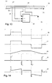
- Fig. 14 illustrates an example unary signal waveform and associated suitable drive waveforms for acoustic transducers with various dynamical properties in order to produce acoustic pulses of approximately square shape.
- Fig. 15 illustrates simplified logic for a digital pulse width modulation (PWM) system for producing linear ramp PWM waveforms from a unary signal and a sign (polarity) signal.
- PWM digital pulse width modulation
- Fig. 16 illustrates the conventional manner of interconnecting the counters and the magnitude comparator that are components of the system shown in Fig. 15.
- Fig. 17 illustrates typical PWM waveforms produced by the circuit of Fig. 15 with the interconnection pattern shown in Fig. 16.
- Fig. 18 illustrates an improved method of interconnecting the counters and magnitude comparator of Fig. 15.
- Fig. 19 illustrates the improved PWM waveforms produced by the interconnection pattern of Fig. 18 when applied to the circuit of Fig. 15.
- Fig. 20 illustrates a simple logic circuit for producing a dual bipolar impulse drive for a transducer with inertia-dominated dynamics.
- Fig. 21 illustrates typical waveforms for the circuit shown in Fig. 20.
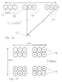
- Fig. 22 illustrates the time-delay problems caused by extended arrays of multiple acoustic transducers.
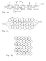
- Fig. 23 illustrates how much more compact an array of acoustic transducers may be made by arraying them in two dimensions rather than one.
- Fig. 24 illustrates in section how multiple two-dimensional arrays of transducers may be stacked in three dimensions to produce a more compact sound source when gaps are placed in each array to allow through the passage of sound.
- Fig. 25 illustrates in plan view a similar arrangement to Fig.24.
- Fig. 26 illustrates a compact two-dimensional array of transducers each positioned so that it is adjacent to transducers associated with adjacent signal levels.
- Fig. 27 illustrates the different path lengths between a listener and the various transducers in an array of transducers.
- Fig. 28 illustrates a method of applying differential signal delays to each transducer in an array in order to compensate for differential listener-to-transducer path lengths.
- Fig. 29 illustrates how a delay system as illustrated in Fig. 28 may be made variable and programmable either dynamically or statically.
- Fig. 30 illustrates in block diagram form a system to select the most significant non-zero bits of an input signal and apply them to a number of unary transducers so as to maintain the desired input-output relationship whilst maintaining the highest possible resolution.
- Fig. 31 illustrates in block diagram form a loudspeaker incorporating most of the inventions and designs described herein.
- Fig. 1 illustrates a digital loudspeaker in which the present invention may be applied.
- a digital input signal of some kind representing a sound pressure waveform is received by the apparatus at the input buffer 1 on n input signal paths.
- This digital signal may be in any digital code form (e.g. binary code, decimal code, in serial or parallel format).
- binary code input signal of n bits, where one of the bits is a sign bit indicating the polarity of the input signal though the invention is not in any way limited to this input format.
- the input buffer 1 presents a uniform impedance to the input signal(s) and performs any necessary level conversion and/or serial to parallel conversion before presenting the n parallel binary bits to the encoder 2.
- the N output signals including the sign signal from the encoder 2 are applied to the transducer drivers 3 which convert the N unary signals from the encoder 2 into N- 1 sets of signals of appropriate current, voltage, pulse shape and polarity to separately drive N- 1 acoustic output transducers shown collectively in Fig. 1 at 4 to which the transducer drivers 3 are connected.
- the N -1 sets of signals may be each a single bipolar signal with all N -1 transducers sharing a common return (not shown), or alternatively, may each be a pair of push-pull signals.
- the set of N -1 acoustic output transducers 4 each of which is substantially identical to the others convert the electrical drive signals into uniform acoustic pulses each of amplitude a and polarity as indicated by the input sign bit.
- the total acoustic output pressure from the system illustrated in Fig. 1 has the same polarity as the input signal and amplitude
- the input buffer 1 is straightforward and will not be described further.
- the unary digital encoder 2 may be implemented in any of the standard ways familiar to those versed in the art of digital electronics, including suitably connected gates, programmable logic devices and read-only memory look up tables. The definition of the decoding function to be implemented will be illustrated for the case of an n -bit signed binary input.
- Fig. 2 illustrates a trivial 1-bit unipolar binary to unary encoder
- Fig. 3 illustrates a 2-bit version
- Fig. 4 a 3-bit version of unipolar binary to unary encoders.
- Fig. 5 illustrates a 3-bit offset binary to unary encoder 5 .
- the binary code is interpreted as a bipolar signal (offset binary code)
- offset binary code one has to define the code representing zero output sound pressure.
- code 011 2 or 100 2 For a 3-bit offset binary system this is usually taken as code 011 2 or 100 2 .
- the table below shows how this would be encoded into unary signals, some representing positive pressure outputs and some negative pressure outputs, where we have assumed code 100 2 represents zero.
- decimal value of the analogue input value represented is also shown in the column labelled i/p: decimal binary negative outputs positive outputs i/p bit 2 bit 1 bit 0 op1 op2 op 3 op4 op5 op6 op7 -4 0 0 0 1 1 1 1 0 0 0 -3 0 0 1 1 1 1 0 0 0 0 -2 0 1 0 1 1 1 0 0 0 0 0 0 0 -1 0 1 1 1 0 0 0 0 0 0 0 0 0 1 0 0 0 0 0 0 0 1 0 1 0 0 0 0 0 0 1 0 1 0 0 0 0 0 1 0 2 1 1 0 0 0 0 0 0 0 0 1 1 0 3 1 1 1 0 0 0 0 0 1 1 1 1 1 1 1 0 0
- i/p is given in decimal and represents a bipolar input signal level, and bits 0 to 2 are the same thing in binary.
- the unary digit outputs op1 to op4 will be used to drive negative pressure transducers, whilst unary digit outputs op5 to op7 will be used to drive positive pressure transducers.
- none of the negative pressure outputs op1 to op4 are on (value 1) when any of the positive pressure outputs op5 to op7 are on (value 1).
- Fig. 6 may be seen how pairs of outputs from the encoder 5 can be applied to acoustic transducers 6 to provide bipolar drive and thus bipolar pressure wave outputs.
- op1 is paired with op5 to drive one transducer
- op2 & op6, and op3 & op7 are similarly paired.
- op4 can either be used for unipolar drive of an additional transducer 7 , or simply not used at all, as no matching positive output signal is available to pair it with.
- Fig. 7 shows a simple implementation of this truth table, and once again illustrates that the conversion can be achieved with just 2 levels of simple gates.
- the gates marked ni in Fig. 7 are simple non-inverting gates used to more equally balance the propagation delay between input and output of all the paths through the encoder.
- the n input signals can be thought of as 2 sets of n /2 bits.
- the straightforward n-bit encoder will have order of ( n -1).2 n gates.
- the scheme shown in Fig. 9 uses two n /2 bit encoders 9 between which the n binary bits 11 are equally divided, and a little additional simple gating in the logic blocks 10.
- each of the 2 n /2 logic blocks 10 is provided with an ALL input, which when turned ON, turns on all the outputs of the logic block; in addition there is an ENABLE input, which must be turned ON if any of the standard inputs is to be able to turn on its corresponding output.
- the 2 n /2 -1 unary outputs from the upper encoder 9 are used in addition to the 2 n /2 -1 outputs from each of the 2 n /2 logic blocks 10 in the relative positions shown in Fig. 9.
- FIG. 11 A different scheme for implementing an n -bit binary to unary encoder is illustrated schematically in Fig. 11, where the n -bit binary input signal 12 is applied via the bus controller 13 to a common data and control bus 14, to which are connected a series of r identical encoder submodules m 1 , m 2 , m 3 , ... m, shown at 15, each with p encoded unary outputs grouped as G 1 , G 2 , G 3 , ... G r , shown at 16.
- the nature of the bus structure allows a variable number of identical modules 15 to be added to the bus 14 to provide a variable bit-width binary to unary encoding scheme.
- the bus controller 13 initialises all the modules 15 via the control and data bus 14 at power-on or reset time, giving each of them a unique address.
- n -bit binary data fed into the bus controller at 12 is passed in parallel to all the submodules 15, and depending on each module's address (initialised by the bus controller as described) the modules 15 each decode a unique range of the of the n -bit binary input signal values into p unary outputs, for a total of p.r unary outputs.
- the submodules 15 are implemented as shown in Fig.
- n -bit binary input data section of bus 14 is seen to split into two groups of bits, 21 and 22, with group 21 comprising the q low order data bits and group 22 comprising the n-q-1 high order data bits (excluding the data sign bit) of the bus 14.
- the q low order data bits 21 are fed into a q -bit unipolar binary to unary encoder 18 where they are converted into p output unary signals at 23 which in turn are connected to the uin inputs of logic block 20.
- Logic block 20 acts as a switch between the p unary signals 23 at its input uin and the p unary signals 16 at its output uout , and is controlled by two input lines All and Enable.
- All input is on (logic 1) then all p unary outputs 16 are turned on, independent of all other inputs to block 20. If the Enable input is on, then each of the p unary outputs 16 take on the state of the corresponding one of the p unary inputs 23, providing a straight-through gating function. Finally, if neither All nor Enable is on, then all p unary outputs 16 are turned off.
- the n-q-1 high order data bits (excluding the data sign bit) 22 of the bus 14 are connected to a latch 17 and a magnitude comparator 19.
- the latch is controlled by signals from control block 25 which in turn connects to the data and control bus 14 via the bus signals 24 , which serve to allow the bus controller 13 to load a unique value into each latch 17 at system initialisation time via a mechanism described below (and illustrated in Fig. 13 described later).
- the n-q-1 bit value stored in latch 17 which is fed to input B of n-q-1 bit magnitude comparator 19, is continuously compared to the value on the upper n-q-1 data lines (excluding the sign bit) of the data and control bus 14 which is fed to input A of magnitude comparator 19.
- the nett effect of this circuitry is that whenever the binary input data has a value less than the value held in the latch 17 (taking into account its bit significance) then none of the p unary outputs of a submodule 15 will be on. Whenever the binary input data has a value greater than the value held in the latch 17 (taking into account its bit significance) then all of the p unary outputs of a block 15 will be on. Finally when the binary input data has a value equal to the value held in the latch 17 (taking into account its bit significance) then the remaining q low order bits will be encoded into p unary outputs by encoder 18.
- Fig. 13 illustrates a general method of allowing the interconnection of multiple identical modules on a parallel bus structure and providing means of independently controlling each of them, even though they contain no hardwired unique identification codes.
- 27 represents a data and/or control bus for connection to multiple modules in parallel, similar to, e.g., the data and control bus 14 in Fig. 12.
- One of the lines in the bus 27 is shown separately as 26 and 32 , and is broken at each module connection location on the bus as shown at 35.
- the end of the bus in the direction of the bus controller e.g. 13 in Fig.
- Only module 1 will respond to the control information as it will be the only module whose line 31 is at logic high as previously described. Thereafter, the bus controller maintains a logic 0 on the Din control line 26, and issues successive clock pulses on line 29 which have the effect of shifting out the logic high on line 31 of one module into the flip-flop 30 of the next module, whilst shifting in logic zeroes everywhere else, the whole structure operating similarly to a serial shift register, and between successive clock pulses the bus controller issues programming and control information for the one module currently activated by its control line 31 which is currently holding the single pulse in the shift register structure so formed.
- the bus controller may additionally be connected to the far end of the control bus (away from the bus controller) via a spare line, connected to line 32 in the last module only on the bus, and in this way, by awaiting the arrival of the shifted-through pulse in the shift register, the bus controller can determine that all modules on the bus have been programmed, and may also count the number of such modules present, which is useful in a variable modular structure where flexible programmability is desired.
- the transducer drivers 3 have to raise the digital signal levels to a power level adequate to produce the desired output sound power, taking into account the efficiency of the output transducers.
- the level required will depend on the type of transducers used, e.g. piezo-electric, electrostatic, moving-coil magnetic, magnetorestrictive.
- the transducer drivers 3 are simply pulse amplifiers. In practical terms, they may also be required to produce some pulse shaping, to compensate for the transfer function of the transducers 4, so as to maintain an approximately square sound-pulse shape.
- p the output sound power of a single transducer.
- Fig. 14 shows five electrical waveforms 36, 37, 38, 39, 40 as a function of time along the horizontal axis.
- 36 represents a typical bipolar unary electrical signal available from the binary to unary encoder after combination with the sign information, which corresponds to the desired pressure output from one transducer of the digital loudspeaker that is the subject of this invention.
- the waveform section shown encompasses a period of zero pressure demand between time O and time A , a constant positive pressure demand from time A to time B, a further period of zero pressure demand from B to C, followed by a period of constant negative pressure demand from C to D, and thereafter zero pressure demand.
- waveform 37 is illustrative of the required velocity profile with time for a transducer to produce the pressure profile shown in 36 .
- waveform 37 (which is substantially the same as 36 apart from perhaps scale) represents a suitable force-time profile to achieve the desired pressure waveshape in 36 , and in turn is also a suitable electrical drive waveshape, so essentially no pulse shaping is required in this case.
- waveform 38 represents a suitable force-time profile to achieve the desired pressure waveshape in 36, where it will be seen to consist of constant ramp rate sections between A and B , and C and D, of opposite slope, and constant levels of zero slope elsewhere, since such constant ramp rates correspond to linear increases of force, and thus displacement with time, resulting in approximately constant pressure output for these periods.
- waveform 39 represents a suitable force-time profile to achieve the desired pressure waveshape in 36, where at time A a short duration positive driving force terminating at time A ' is produced to give a positive impulse of momentum to the transducer's moving mass, after which the mass coasts at approximately constant positive velocity until time B , where it is given a short negative impulse until time B' to bring it quickly to rest again, whereafter at time C a further short negative impulse is given until time C' to give the moving mass a negative impulse of momentum, followed by a further coasting period at substantially constant negative velocity until time D at which a short positive impulse until time D' is applied once more bringing the moving mass to rest.
- a composite drive waveform comprising some suitable linear combination of 37 , 38 and 39 may be applied to produce square-form acoustic pulse pressure output as required.
- Waveform 37 may be produced with high electrical efficiency in a standard pulse amplifier.
- Waveform 38 may also be produced with high electrical efficiency by means of pulse-width-modulation (PWM) of a suitably high frequency pulse waveform in the following manner.
- Fig. 15 illustrates a novel digital pulse width modulation ramp generator, comprising a high frequency clock generator 41, which feeds into the clock input of a k -bit binary counter 42 with parallel binary output QR at 52 which in turn feeds into one of the two parallel binary inputs ( B in this case) of a k -bit binary magnitude comparator 43.
- the unary signal U n shown at 47 which is to be shaped as a ramp as shown for example at 38 in Fig. 14, is connected to the other input of the AND gate 45 with the result that whenever U n is at logic one, clock pulses from d of divider 44 issue from the output of the AND gate 45 from where they are connected to the clock input of k -bit binary up/down counter 46, and otherwise the output of the AND gate is at logic low.
- Up/down counter 46 has its up/down control input connected to the sign-bit (or unary sign signal) of the digital loudspeaker circuitry and determines whether counter 46 will count up when a clock pulse arrives at its input, or count down.
- the reset input of counter 46 is arranged to set the counter to half full count when activated (e.g.
- the k -bit parallel binary output QI of up/down counter 46 is connected to the parallel binary input A of comparator 43, such that the comparator continuously determines the magnitude of the output QI of 46 relative to the magnitude of the output QR of 42, output A>B of comparator 43 then being at logic high whenever QI > QR. Details of data synchronization are not shown for simplicity.
- counter 46 starts from this state, when U n goes to logic high, then depending on the state of the Sign input, counter 46 either counts up or down from its initial half full count at a constant rate determined by the divided clock signal 51 so that its instantaneous output value V available in parallel binary at QI from counter 46 is linearly varying with time at a rate of f/D counts per sec, where D is the division ratio of clock divider 44. If the clock rate f of counter 42 is large compared with f/D (i.e.
- V may be assumed substantially constant over a counter 42 period P, in which case the PWM signal 50 will be high for the fraction V/ (2 k -1) of the period P where 0 ⁇ V ⁇ (2 k -1), which is exactly the condition required for the signal 50 to be a linear pulse width modulated representation of value V. It can be shown that even when the condition f » f/D does not hold, that the circuit still produces linear pulse width modulated signals at output 50.
- the effective value of the PWM output 50 (which is just the time average of output 50 during a period as long as or longer than the peiod P ) is a linear ramp while U n is on and a static value when U n is off, which is precisely the condition required to generate the type of waveform illustrated at 38 in Fig. 14, for driving spring-limited transducers to produce clean square digital acoustic pulse outputs.
- circuit components 41, 42 and 44 may be shared amongst a large number of individual PWM generators assigned each to a distinct unary output U n , so the saving in parts is considerable. It should be noted that this digital method of creating pulse width modulated (PWM) waveforms has applications outside of digital loudspeakers wherever PWM is useful.
- Fig. 16 shows in some more detail the conventional method of interconnecting the two counters 42 and 46 to the magnitude comparator 43, where it will be seen that the least significant bit outputs of the counters 46 and 42 shown as q 0 , q 1 , q 2 , ...
- Waveform 52 results because while counter 42 is in the first five states 0 to 4 its output is less than that of counter 46 assumed static at value 5 in this example, and so the A>B output of the comparator is at logic high for these states, after which it goes low for the rest of the counter 42 's cycle.
- the improved version of the circuit shown in Fig.
- bit-reversal ordering gives the maximum number of output transitions over the full range of PWM output states.
- bit-reversed ordering produces an output at 50 that transitions on each clock pulse to counter 42 when the counter 46 is at half-full count, which is the maximum possible output frequency from such a circuit, with 50% or 1:1 mark-space ratio.
- FIG. 20 A digital method of producing a waveform of the type shown at 39 in Fig. 14, for the driving of mass-limited (inertia dominated) acoustic transducers is illustrated in Fig. 20, where a unary input signal U n at 58 and the Sign signal drive the clock inputs Clk of a pair of flip-flops 57 and 60 via a pair of exclusive-OR gates 59 and 62 and an inverter 64, in such a way as to clock in a logic-1 into the D input of one of the flip-flops on the leading edge of the U n signal and into the other flip-flip on the trailing edge, which flip-flop responds to which edge being dependent on the Sign signal.
- a unary input signal U n at 58 and the Sign signal drive the clock inputs Clk of a pair of flip-flops 57 and 60 via a pair of exclusive-OR gates 59 and 62 and an inverter 64, in such a way as to clock in a logic-1 into the D input of one
- the output of the digital loudspeaker is synthesised from a large number of pulses, rather than smooth analogue waveforms, there will be frequency components in the output outside the normal range of hearing, generally reckoned to be ⁇ 20Hz to ⁇ 20KHz. As these components are by definition inaudible to humans, it is possible to simply ignore them. However, loud sounds in the range 20KHz to 60KHz can cause a certain amount of alarm and distress in domestic animals, and it may be necessary to reduce such emissions as much as possible.
- One approach is to place an acoustic low-pass filter over the output transducer array to absorb such frequencies directly at their point of generation.
- a material with a heavy sound absorption above ⁇ 20KHz but which is practically acoustically transparent below ⁇ 20KHz will provide the required filtering.
- a second approach is to minimise the high frequency emissions from the transducers themselves. This can be done by ensuring that even at the highest frequency of operation, the resolution of the digital loudspeaker (in terms of bits, or unary digits) is kept as high as possible.
- the Nyquist theorem tells us that to adequately reproduce a 20KHz sine wave from digital samples we need to sample at a frequency of at least 40KHz.
- reproduction of a sine wave from so few samples i.e. just 2 per cycle, when sampling at the nyquist rate
- the filtering requirements can be much reduced if instead we sample at a rate much higher than the nyquist rate.
- the digital input signal is available at a suitably high sampling rate then no more needs to be done other than to maintain that sampling rate throughout the digital loudspeaker. If, however, one was to drive a practical digital loudspeaker from, say, digital audio signals derived from a Compact Disc, which is sampled at ⁇ 44KHz, then one would need to interpolate the digital samples to create a higher sample rate. Such a process is already done to some extent in better quality compact disc players to ease the filtering requirements when converting the digital signals to electrical analogue signals for further amplification. Here, we are suggesting that a similar process be performed on low-sampling rate digital input signals to ensure that the sound output signals from the digital transducers of the digital loudspeaker should have less spurious high frequency content.
- This design of digital loudspeaker using unary code at the output transducers ensures that individual transducers will turn on and off only once per cycle of sine wave output, independent of the resolution of the digital output, enabling this digital interpolation process to be carried out to any degree without increasing the specifications of the output transducers in terms of their frequency response. This independence is not the case if binary, ternary, or other number- (greater than or equal to 2) -based digital coding is used.
- the transducer array In order to minimize the least acceptable listening distance, it is therefore important to minimize the spatial extent of the transducer array. This can be done by laying out the transducers 70 in as tight a two dimensional arrangement as possible, and regular circular, hexagonal and square array shapes are close to optimum from this perspective. For the example above, if a square array of 1024 30mm diameter transducers 70 was laid out as per Fig. 23, then the array becomes 960mm wide by 960mm high (i.e. 32 times shorter than the linear array sketched in Fig. 22, and the corresponding listening distance falls from 32m to ⁇ 1m which is much more practical.
- a second way to minimize the extent of the array of a given number of transducers is to make the transducers themselves smaller across their aperture. For example, for the array shown in Fig. 23, if the transducers 70 were 3mm across their aperture instead of 30mm, then the array of 32 x 32 transducers could be made as small as 96mm square, and the minimum listening distance according to the same criterion as described above, would fall to 10cm.
- the array size can be reduced even further by producing a multi-layered three dimensional arrangement of transducers where a front two-dimensional array of transducers is placed over one or more further two-dimensional arrays of transducers behind it, with the sound from the rear arrays passing through gaps between the front arrays, or through holes in the transducers themselves.
- the transducers are necessarily circular (for example, because of their method of construction), then any regular array of circular devices necessarily has gaps in it, as circles of one size do not tessellate. This multi-layered two dimensional arrangement then becomes attractive, and allows a very compact array to be constructed, even when using a large number of transducers.
- Fig. 24 showing a side view
- Fig. 25 showing a front view of such a three-dimensional array of transducers illustrates these principles.
- unary digital code has no particular positional significance, we are free to connect the unary digital outputs from the transducer drivers, to transducers in the array(s) in any spatial manner suitable. As quieter sounds will be reproduced with smaller total numbers of transducers active than louder sounds, it is optimal to keep transducers related to adjacent input signal levels, physically adjacent in the output transducer array. In this manner, the overall size of the sound source is kept as compact as possible at all sound output levels. Furthermore, if the geometric centre of the group of transducers used to reproduce any particular sound level, is kept as close to the geometric centre of the whole array as possible, then the apparent sound source position will appear to move the least with changes in reproduced sound level.
- Fig. 26 illustrates this principle for the special case of a hexagonal two dimensional array of circular transducers. Its extension to square arrays and other regular two-dimensional and three-dimensional array structures is straightforward.
- delay devices can be very simple (e.g. a 1 bit wide shift register, or suitably addressed RAM storage elements).
- the arrangement of the delays is such that the transducers closest to the listening position are delayed the most, and those furthest from it, the least, or not at all, so as to give the sound from the distant transducers a 'head-start'.
- the delay applied would be quantised to the nearest integral multiple of a suitable delay time (e.g. 5 ⁇ s, for maximum 10% error on a 20KHz output signal).
- a digital delay system with a 200KHz clock and variable length real or synthesised shift registers in each transducer driver path would suffice.
- ASIC Application Specific Integrated Circuit
- the outputs of the delay generators 76 eventually drive transducers 74 as shown schematically.
- the program delay information 75 can either be set up once before each use of the loudspeaker, or could alternatively be varied dynamically throughout the use of the speaker, and one application of this would be to track the listener's position relative to the loudspeaker and optimise the delay pattern t l to t N for his current position.
- the digital nature of the output transducers allows a method of volume level control that ensures that maximum signal resolution and maximum signal-to-noise ratio is attained at all levels of listening, with particular advantages at low listening levels.
- a conventional (analogue) hi-fi amplifier the system volume control is usually placed somewhere before the main power amplifier in the input-to-output path of the system. The effect of this is that the power amplifier itself is always operating at the same power-level regime (i.e. always capable of full power output) and more importantly, always produces the same absolute level n of self-generated spurious output noise.
- the perceived signal-noise-ratio ( snr ) of the amplifier is p/n .
- the perceived amplifier snr is ( p/l ) /n , i.e. the snr is reduced by the factor l .
- the DLS allows at least two methods of volume reduction in the amplifier itself, right at the power generation point, so that noise and signal are reduced together, thus maintaining the inherent snr of the DLS/amplifier combination.
- Method 1 is to supply the output pulse amplifiers from a variable power supply level, so that smaller pulse amplitudes are produced when a lower volume setting is used.
- the power supply output voltage would be made to depend in some way, on the volume level setting chosen. In this case, output power is proportional to the square of supply voltage, giving a wide power output range whilst keeping the supply level within operating limits of the pulse amplifiers.
- Method 2 applies pulse-width control to the output transducer drivers, so that whereas normally the transducers would either be on or off for an entire digital clock cycle, by contrast with pulse width control, the transducers that were previously on for the whole of each digital clock cycle would all be gated off for a same proportion of each such cycle. If the proportion of a cycle gated off was x % then output power would be reduced to (100- x )%, so with this method control is proportional to x 1 . However, apart from limitations caused by the finite rise and fall times of the transducer driver output pulse amplifiers, this method allows very wide range power level control, and may be implemented entirely digitally.
- the method described above for volume control and low-level listening noise reduction can also be used to reduce the total number of transducers needed in a DLS without reducing the effective resolution of the sound output.
- the method works by dynamically applying the low-level listening technique as a function of the actual level of the input signal.
- Fig.30 illustrates a possible method of implementing this scheme.
- an n-bit binary input signal 88 is to be reproduced with an m-bit digital loudspeaker where m ⁇ n.
- the n-bit input signal 88 is fed into a digital buffer memory M at 79 capable of storing at least one half-cycle of the input signal at its lowest frequency (e.g. 50ms for a 20Hz low frequency limit). It is simultaneously fed to a comparator C at 85 and maximum value storage latch X at 86 , such that during the half cycle, successively greater input values become stored in the maximum value latch 86 .
- a zero crossing detector Z at 81 provides a signal at the end of each input half cycle.
- the value in the maximum value latch 86 indicates how large is the biggest signal stored in the buffer 79 , containing the digital input samples yet to be reproduced (as they have been buffered in 79 and thus delayed). During the next half cycle, these stored samples will be read out of 79 and reproduced by the loudspeaker whilst new values for the next half cycle are being stored. At the end of the half cycle, then, the value in 86 is latched into the number-of-bits register B at 84, which outputs an integer in the range 0 to n-m (where m ⁇ n as before).
- This number is used to select the power level to be used by the output transducer drivers 83 for the half cycle (which may be controlled by a pulse width modulation technique, or a supply voltage variation technique, or both in combination, as described previously). It is also used to select which of the unsigned input bits 0 to n-2 will be passed from the buffer 79 to the binary to unary encoder U at 82 . This selection is done by an m-bit wide, n-m way selector block S at 80 , which takes its digital signal input from buffer 79 (n bits wide) and sends m of those bits onto the unary encoder 82 . Which bits it selects are determined by the signal from register 84.
- Typical savings provided by this technique are: for a 16-bit audio digital signal and a 10-bit digital loudspeaker provided with the floating point bit representation system just discussed, the digital loudspeaker would require only 1023 transducers and drivers to reproduce sounds to 10 bit (unipolar) precision over a 16-bit dynamic range, as compared to a 16-bit DLS which would require 32767 transducers - i.e. a saving of over 31,000 transducers.
- this technique makes practicable the construction of unary-based digital loudspeakers with very high dynamic range and adequate precision, at relatively low cost.
- n -bit binary form from mixer 89 to a digital interpolator 97 where the effective sampling rate of the input signal is optionally increased before the n -bit data is passed to the signal delay store and magnitude detector 95 where the input signal is delayed for a time up to half the period of the lowest audio frequency to be reproduced, and where the peak magnitude of the delayed signal is determined whose value is used to produce control signals 91 and 93.
- the delayed n -bit binary signal data are then passed to an m -bit ( n-m ) way selector (where m ⁇ n-1 ) controlled by signal 91, which emits m output binary (non-sign) bits connected to the input of binary-to-unary encoder 2 .
- the sign bit is separately connected from delay store 95 directly to encoder 2 as shown at 98.
- the effect of store 95 and selector 80 are to select up to m bits plus sign of the n -bit input signal in such a way that the m most significant adjacent non-sign bits with a leading 1 are contained in the m -bit subset.
- the N unary signals are then fed to a variable length digital delay generator 76 controlled by delay programmer 78 whose mode of operation may be modified by the user at 96 , where the differential delay of the various N unary signals may be adjusted to compensate for transducer 4 positions relative to listening position.
- the possibly delayed Nunary signals then pass through pulse shaper 88 which may modify the square profile input pulses (not the sign signal) to different pulse shapes appropriate to the type of transducers 4 used, after which the N unary signals pass to the N -1 transducer drivers 3 which drive the N -1 transducers 4, the latter providing acoustic pulses which in combination constitute the output sound reproduced.
- the transducer drivers 4 are controlled by a signal from the power level controller 94 which in turn is controlled by an input from the magnitude detector in 95 and also by user input which may include volume level selection.
- This control signal on drivers 3 is to modify the mean output power delivered to each of the transducers 4 when activated by a pulse signal, in such a way that the mean power level from the array of transducers 4 may be varied, in the presence of a fixed level input signal.
- the digital loudspeaker has application in all instances where analogue loudspeakers are currently used, including reproduction of music and speech and other sounds in domestic and commercial equipment, including radios, televisions, record compact disc and tape players, music centres, hi-fidelity sound systems, public address systems, sound reinforcement systems, home theatres, cinemas, theatres, background music systems, bands, portable sound reproduction equipment, in-car entertainment systems, and in miniaturised form in headphones.
- analogue loudspeakers including reproduction of music and speech and other sounds in domestic and commercial equipment, including radios, televisions, record compact disc and tape players, music centres, hi-fidelity sound systems, public address systems, sound reinforcement systems, home theatres, cinemas, theatres, background music systems, bands, portable sound reproduction equipment, in-car entertainment systems, and in miniaturised form in headphones.
- the advantages of this digital loudspeaker design over existing loudspeaker designs in these applications include: higher quality and lower distortion reproduction; flatter form factor than most cabinet-enclosed analogue loudspeakers; greater stability due to digital rather than analogue electronics; elimination of requirement for separate linear power amplifier from the sound reproduction system; lighter weight; greater portability; easier manufacture to consistent high quality standard; mass production techniques may be applied to the transducer array assemblies; higher efficiency and therefore lower power consumption and consequent longer operation time from battery power sources; scalable design allows balancing of required precision against cost and complexity in a uniform manner as lower distortion may be achieved simply by the addition of more components of identical precision; produces essentially zero output noise when input signal is zero (i.e. very high signal to noise ratio).
Landscapes
- Health & Medical Sciences (AREA)
- Otolaryngology (AREA)
- Physics & Mathematics (AREA)
- Engineering & Computer Science (AREA)
- Acoustics & Sound (AREA)
- Signal Processing (AREA)
- General Health & Medical Sciences (AREA)
- Circuit For Audible Band Transducer (AREA)
- Analogue/Digital Conversion (AREA)
- Stereophonic System (AREA)
- Diaphragms For Electromechanical Transducers (AREA)
- Amplifiers (AREA)
- Obtaining Desirable Characteristics In Audible-Bandwidth Transducers (AREA)
- Dc-Dc Converters (AREA)
- Piezo-Electric Transducers For Audible Bands (AREA)
- Details Of Audible-Bandwidth Transducers (AREA)
- Oscillators With Electromechanical Resonators (AREA)
- Transmission Systems Not Characterized By The Medium Used For Transmission (AREA)
- Details Of Television Scanning (AREA)
Applications Claiming Priority (3)
| Application Number | Priority Date | Filing Date | Title |
|---|---|---|---|
| GB9506725 | 1995-03-31 | ||
| GBGB9506725.2A GB9506725D0 (en) | 1995-03-31 | 1995-03-31 | Improvements in or relating to loudspeakers |
| EP96907605A EP0818122B1 (de) | 1995-03-31 | 1996-03-27 | Massnahmen zur verbesserung von lautsprechern |
Related Parent Applications (1)
| Application Number | Title | Priority Date | Filing Date |
|---|---|---|---|
| EP96907605A Division EP0818122B1 (de) | 1995-03-31 | 1996-03-27 | Massnahmen zur verbesserung von lautsprechern |
Publications (3)
| Publication Number | Publication Date |
|---|---|
| EP1122973A2 true EP1122973A2 (de) | 2001-08-08 |
| EP1122973A3 EP1122973A3 (de) | 2002-09-04 |
| EP1122973B1 EP1122973B1 (de) | 2005-10-12 |
Family
ID=10772301
Family Applications (2)
| Application Number | Title | Priority Date | Filing Date |
|---|---|---|---|
| EP96907605A Expired - Lifetime EP0818122B1 (de) | 1995-03-31 | 1996-03-27 | Massnahmen zur verbesserung von lautsprechern |
| EP01108918A Expired - Lifetime EP1122973B1 (de) | 1995-03-31 | 1996-03-27 | Digitaler Pulsbreiten-Modulationsgenerator |
Family Applications Before (1)
| Application Number | Title | Priority Date | Filing Date |
|---|---|---|---|
| EP96907605A Expired - Lifetime EP0818122B1 (de) | 1995-03-31 | 1996-03-27 | Massnahmen zur verbesserung von lautsprechern |
Country Status (10)
| Country | Link |
|---|---|
| US (3) | US6373955B1 (de) |
| EP (2) | EP0818122B1 (de) |
| JP (1) | JP3492698B2 (de) |
| CN (2) | CN1575037A (de) |
| AT (2) | ATE211345T1 (de) |
| AU (1) | AU5117096A (de) |
| DE (2) | DE69635286D1 (de) |
| DK (1) | DK0818122T3 (de) |
| GB (1) | GB9506725D0 (de) |
| WO (1) | WO1996031086A1 (de) |
Cited By (8)
| Publication number | Priority date | Publication date | Assignee | Title |
|---|---|---|---|---|
| WO2003059005A3 (en) * | 2002-01-08 | 2003-12-04 | 1 Ltd | Digital loudspeaker system |
| US7319641B2 (en) | 2001-10-11 | 2008-01-15 | 1 . . . Limited | Signal processing device for acoustic transducer array |
| DE102005001174B4 (de) * | 2004-04-15 | 2008-07-31 | Avago Technologies General Ip (Singapore) Pte. Ltd. | Pulsbreitenmodulationssysteme und -verfahren |
| US7515719B2 (en) | 2001-03-27 | 2009-04-07 | Cambridge Mechatronics Limited | Method and apparatus to create a sound field |
| US7577260B1 (en) | 1999-09-29 | 2009-08-18 | Cambridge Mechatronics Limited | Method and apparatus to direct sound |
| TWI461884B (zh) * | 2011-04-06 | 2014-11-21 | Himax Imagimg Inc | 用來產生輸出時脈訊號的時脈產生電路及相關方法 |
| US10623882B1 (en) * | 2019-04-03 | 2020-04-14 | xMEMS Labs, Inc. | Sounding system and sounding method |
| US10681488B1 (en) | 2019-03-03 | 2020-06-09 | xMEMS Labs, Inc. | Sound producing apparatus and sound producing system |
Families Citing this family (106)
| Publication number | Priority date | Publication date | Assignee | Title |
|---|---|---|---|---|
| GB9506725D0 (en) * | 1995-03-31 | 1995-05-24 | Hooley Anthony | Improvements in or relating to loudspeakers |
| FR2765765B1 (fr) * | 1997-07-07 | 2002-12-06 | Pierre Piccaluga | Procede et appareil pour formater le signal audio numerique pour l'usage de la reproduction sonore |
| FR2790353B1 (fr) * | 1999-02-25 | 2002-11-15 | Olivier Viacava | Enceinte audio-numerique effectuant la conversion numerique vers analogique directement dans l'air |
| DE19923170A1 (de) * | 1999-05-21 | 2000-11-23 | Florian M Koenig | Volldigitale Tonsignal-Versorgung von Schallwandlern |
| EP1063866B1 (de) * | 1999-05-28 | 2008-11-26 | Texas Instruments Inc. | Digitaler Lautsprecher |
| EP1071218B1 (de) | 1999-07-19 | 2009-09-09 | Texas Instruments Inc. | Differenzielle monadische Kodierung für digitales Audiosignal |
| GB9926489D0 (en) * | 1999-11-10 | 2000-01-12 | New Transducers Ltd | Digital loudspeaker |
| GB0009133D0 (en) * | 2000-04-14 | 2000-05-31 | New Transducers Ltd | Acoustic device and method for driving it |
| DE10026474B4 (de) * | 2000-05-27 | 2005-06-09 | Sennheiser Electronic Gmbh & Co. Kg | Wandler mit halbleitender Membran |
| US6895378B1 (en) * | 2000-09-22 | 2005-05-17 | Meyer Sound Laboratories, Incorporated | System and method for producing acoustic response predictions via a communications network |
| US20020055827A1 (en) * | 2000-10-06 | 2002-05-09 | Chris Kyriakakis | Modeling of head related transfer functions for immersive audio using a state-space approach |
| EP1206160A1 (de) * | 2000-11-09 | 2002-05-15 | Texas Instruments Incorporated | Digitaler Lautsprecher |
| US7284256B2 (en) * | 2000-12-04 | 2007-10-16 | Sony Corporation | Method and system to maintain relative statistics for creating automatically a list of favorites |
| US7058463B1 (en) * | 2000-12-29 | 2006-06-06 | Nokia Corporation | Method and apparatus for implementing a class D driver and speaker system |
| GB0102865D0 (en) | 2001-02-06 | 2001-03-21 | Secr Defence Brit | Panel form loudspeaker |
| US20020131608A1 (en) * | 2001-03-01 | 2002-09-19 | William Lobb | Method and system for providing digitally focused sound |
| SE0101720D0 (sv) * | 2001-05-16 | 2001-05-16 | Bang & Olufsen Powerhouse As | Apparatus for electric to acoustic conversion |
| US7130430B2 (en) * | 2001-12-18 | 2006-10-31 | Milsap Jeffrey P | Phased array sound system |
| JP3671910B2 (ja) * | 2002-01-16 | 2005-07-13 | 日産自動車株式会社 | 回転電機の接続方法 |
| GB0203895D0 (en) * | 2002-02-19 | 2002-04-03 | 1 Ltd | Compact surround-sound system |
| US7184480B1 (en) * | 2002-09-25 | 2007-02-27 | O2Micro International Limited | Digital PWM generator |
| GB0301093D0 (en) * | 2003-01-17 | 2003-02-19 | 1 Ltd | Set-up method for array-type sound systems |
| US20040166817A1 (en) * | 2003-01-20 | 2004-08-26 | Mehran Mokhtari | System, method and apparatus for burst communications |
| US7216248B2 (en) * | 2003-03-20 | 2007-05-08 | Sun Microsystems, Inc. | On-chip clock generator allowing rapid changes of on-chip clock frequency |
| US7929718B1 (en) * | 2003-05-12 | 2011-04-19 | D2Audio Corporation | Systems and methods for switching and mixing signals in a multi-channel amplifier |
| US7684574B2 (en) * | 2003-05-27 | 2010-03-23 | Harman International Industries, Incorporated | Reflective loudspeaker array |
| US7826622B2 (en) * | 2003-05-27 | 2010-11-02 | Harman International Industries, Incorporated | Constant-beamwidth loudspeaker array |
| JP4007255B2 (ja) | 2003-06-02 | 2007-11-14 | ヤマハ株式会社 | アレースピーカーシステム |
| GB0321676D0 (en) * | 2003-09-16 | 2003-10-15 | 1 Ltd | Digital loudspeaker |
| US8170233B2 (en) * | 2004-02-02 | 2012-05-01 | Harman International Industries, Incorporated | Loudspeaker array system |
| GB0415626D0 (en) * | 2004-07-13 | 2004-08-18 | 1 Ltd | Directional microphone |
| GB0415625D0 (en) * | 2004-07-13 | 2004-08-18 | 1 Ltd | Miniature surround-sound loudspeaker |
| US20070269071A1 (en) * | 2004-08-10 | 2007-11-22 | 1...Limited | Non-Planar Transducer Arrays |
| US7492233B2 (en) * | 2005-04-29 | 2009-02-17 | Honeywell International Inc. | Precision modulated controller output |
| GB0514361D0 (en) * | 2005-07-12 | 2005-08-17 | 1 Ltd | Compact surround sound effects system |
| BRPI0519502B1 (pt) | 2005-10-26 | 2018-10-09 | Thomson Licensing | sistema de televisão via satélite sobre ip |
| US7676049B2 (en) * | 2006-05-12 | 2010-03-09 | Cirrus Logic, Inc. | Reconfigurable audio-video surround sound receiver (AVR) and method |
| US7606377B2 (en) * | 2006-05-12 | 2009-10-20 | Cirrus Logic, Inc. | Method and system for surround sound beam-forming using vertically displaced drivers |
| US7606380B2 (en) * | 2006-04-28 | 2009-10-20 | Cirrus Logic, Inc. | Method and system for sound beam-forming using internal device speakers in conjunction with external speakers |
| US7804972B2 (en) * | 2006-05-12 | 2010-09-28 | Cirrus Logic, Inc. | Method and apparatus for calibrating a sound beam-forming system |
| CN102684699B (zh) | 2006-05-21 | 2015-03-18 | 株式会社特瑞君思半导体 | 声音再现用数据变换装置 |
| US8457338B2 (en) | 2006-05-22 | 2013-06-04 | Audio Pixels Ltd. | Apparatus and methods for generating pressure waves |
| WO2007135679A2 (en) * | 2006-05-22 | 2007-11-29 | Audio Pixels Ltd. | Volume and tone control in direct digital speakers |
| AU2007252847A1 (en) * | 2006-05-22 | 2007-11-29 | Audio Pixels Ltd. | Direct digital speaker apparatus having a desired directivity pattern |
| US7570037B2 (en) * | 2006-11-17 | 2009-08-04 | Virginia Tech Intellectual Properties, Inc. | Hybrid control methods for digital pulse width modulator (DPWM) |
| KR101411183B1 (ko) * | 2007-05-21 | 2014-06-23 | 오디오 픽셀즈 리미티드 | 원하는 지향성 패턴을 가지는 다이렉트 디지털 스피커 장치 |
| DE102007029959A1 (de) * | 2007-06-28 | 2009-01-02 | Robert Bosch Gmbh | Verfahren und Vorrichtung zur Erfassung einer Umgebung |
| KR101292206B1 (ko) * | 2007-10-01 | 2013-08-01 | 삼성전자주식회사 | 어레이 스피커 시스템 및 그 구현 방법 |
| JP5335807B2 (ja) | 2007-11-21 | 2013-11-06 | オーディオ ピクセルズ リミテッド | 改良型スピーカ装置およびそれと連携した有用な方法 |
| JP5396588B2 (ja) | 2008-06-16 | 2014-01-22 | 株式会社 Trigence Semiconductor | デジタルスピーカー駆動装置,デジタルスピーカー装置,アクチュエータ,平面ディスプレイ装置及び携帯電子機器 |
| DE102008038340B4 (de) * | 2008-08-19 | 2010-04-22 | Austriamicrosystems Ag | Schaltungsanordnung zur Ansteuerung einer Lichtquelle und Verfahren zum Erzeugen eines Ansteuersignals für dieselbe |
| EP2326108B1 (de) * | 2009-11-02 | 2015-06-03 | Harman Becker Automotive Systems GmbH | Phasenentzerrung für Audiosystem |
| EP2391014B1 (de) | 2009-12-09 | 2017-12-27 | Trigence Semiconductor, Inc. | Auswahlvorrichtung |
| WO2011074341A1 (ja) | 2009-12-16 | 2011-06-23 | 株式会社 Trigence Semiconductor | 音響システム |
| WO2011111042A1 (en) | 2010-03-11 | 2011-09-15 | Audio Pixels Ltd. | Electrostatic parallel plate actuators whose moving elements are driven only by electrostatic force and methods useful in conjunction therewith |
| CN102316400A (zh) * | 2010-07-02 | 2012-01-11 | 英业达股份有限公司 | 喇叭与应用该喇叭的可携式电子装置 |
| US8693708B2 (en) * | 2010-08-24 | 2014-04-08 | Star Headlight & Lantern Co., Inc. | System for operating a device for producing an audible alarm |
| CN101986721B (zh) | 2010-10-22 | 2014-07-09 | 苏州上声电子有限公司 | 全数字式扬声器装置 |
| US9425708B2 (en) | 2010-11-26 | 2016-08-23 | Audio Pixels Ltd. | Apparatus and methods for individual addressing and noise reduction in actuator arrays |
| DE102011003168A1 (de) * | 2011-01-26 | 2012-07-26 | Robert Bosch Gmbh | Lautsprechersystem |
| US20120244969A1 (en) | 2011-03-25 | 2012-09-27 | May Patents Ltd. | System and Method for a Motion Sensing Device |
| GB2491130B (en) * | 2011-05-23 | 2013-07-10 | Sontia Logic Ltd | Reducing distortion |
| US8897465B2 (en) | 2011-06-01 | 2014-11-25 | Robert Bosch Gmbh | Class D micro-speaker |
| US20130039431A1 (en) * | 2011-08-12 | 2013-02-14 | Electronics And Telecommunications Research Institute | Power-scalable encoding/decoding apparatus and method |
| JP5838927B2 (ja) * | 2011-10-14 | 2016-01-06 | Tdk株式会社 | 積層セラミック電子部品 |
| CN102404672B (zh) | 2011-10-27 | 2013-12-18 | 苏州上声电子有限公司 | 数字化扬声器阵列系统的通道均衡与波束控制方法和装置 |
| CN103152673B (zh) * | 2011-12-07 | 2015-07-08 | 中国科学院声学研究所 | 基于四元码动态失配整形的数字扬声器驱动方法和装置 |
| US9240776B2 (en) * | 2012-01-26 | 2016-01-19 | Rf Micro Devices, Inc. | Analog-digital pulse width modulator (ADPWM) |
| CN103248981B (zh) * | 2012-02-06 | 2016-06-01 | 王永明 | 一种扬声器 |
| CN102684701B (zh) | 2012-04-27 | 2014-07-09 | 苏州上声电子有限公司 | 基于编码转换的数字扬声器驱动方法和装置 |
| WO2013175477A1 (en) | 2012-05-25 | 2013-11-28 | Audio Pixels Ltd. | A system, a method and a computer program product for controlling a set of actuator elements |
| DK2856769T3 (en) | 2012-05-25 | 2018-10-22 | Audio Pixels Ltd | SYSTEM, PROCEDURE AND COMPUTER PROGRAM PRODUCT TO CONTROL A GROUP OF ACTUATOR SYSTEMS FOR CREATING A PHYSICAL EFFECT |
| US20160050492A1 (en) * | 2013-02-26 | 2016-02-18 | The University Of Akron | Direct-drive digital audio amplifier for electrostatic loudspeakers |
| US8934654B2 (en) | 2013-03-13 | 2015-01-13 | Aliphcom | Non-occluded personal audio and communication system |
| US10070211B2 (en) * | 2013-06-28 | 2018-09-04 | Kopin Corporation | Digital voice processing method and system for headset computer |
| US9350336B2 (en) * | 2014-02-05 | 2016-05-24 | Texas Instruments Incorporated | Timing compensation using the system clock |
| CN104022758B (zh) * | 2014-05-29 | 2016-09-28 | 中国人民解放军国防科学技术大学 | 一种带清零置位端口的功耗均衡触发器 |
| KR102197230B1 (ko) * | 2014-10-06 | 2020-12-31 | 한국전자통신연구원 | 음향 특성을 예측하는 오디오 시스템 및 방법 |
| JP6760960B2 (ja) | 2015-04-15 | 2020-09-23 | オーディオ ピクセルズ エルティーディー.Audio Pixels Ltd. | 空間内で少なくとも物体の位置を検出する方法およびシステム |
| KR102340202B1 (ko) | 2015-06-25 | 2021-12-17 | 한국전자통신연구원 | 실내의 반사 특성을 추출하는 오디오 시스템 및 방법 |
| US9621040B2 (en) * | 2015-08-20 | 2017-04-11 | Sanken Electric Co., Ltd. | PWM signal generator and switching power supply device having same |
| US10030961B2 (en) | 2015-11-27 | 2018-07-24 | General Electric Company | Gap measuring device |
| US10557472B2 (en) | 2015-12-17 | 2020-02-11 | Venturedyne, Ltd. | Environmental sensor and method of operating the same |
| EP3390838B1 (de) * | 2015-12-17 | 2021-07-14 | Venturedyne, Ltd | Umgebungssensor |
| US9983596B2 (en) | 2015-12-17 | 2018-05-29 | Venturedyne, Ltd. | Environmental sensor and method of operating the same |
| US9857285B2 (en) | 2015-12-17 | 2018-01-02 | Venturedyne, Ltd. | Environmental sensor and method of operating the same |
| US9813803B1 (en) * | 2016-05-04 | 2017-11-07 | Wu-Hsu Lin | Electrical speaker assembly |
| US10103928B2 (en) * | 2016-05-23 | 2018-10-16 | National Instruments Corporation | Nyquist and square root nyquist filters for pulse shaping in wireless communications |
| US10014869B1 (en) * | 2017-03-08 | 2018-07-03 | Qualcomm Incorporated | Fractional clock generator with ramp control including fixed time interval and coarse/fine frequency change steps |
| CN110402585B (zh) * | 2017-03-10 | 2021-12-24 | 三星电子株式会社 | 室内低频声功率优化方法和装置 |
| US20180315453A1 (en) * | 2017-04-28 | 2018-11-01 | Tymphany Worldwide Enterprises Limited | Audio integrated circuit |
| DE102017221738A1 (de) * | 2017-12-03 | 2019-06-06 | Audi Ag | Verfahren zum Einstellen einer Leistungselektronik |
| CN107948808A (zh) * | 2018-01-12 | 2018-04-20 | 上海联影医疗科技有限公司 | 应用于磁共振系统的耳机和磁共振系统 |
| CN110636407B (zh) * | 2018-06-21 | 2024-06-07 | 刘云轩 | 一种全数字扬声器系统及其工作方法 |
| US10951204B2 (en) * | 2018-08-30 | 2021-03-16 | Maxim Integrated Products, Inc. | Digital pulse width modulation driver system |
| US10484784B1 (en) * | 2018-10-19 | 2019-11-19 | xMEMS Labs, Inc. | Sound producing apparatus |
| US11522448B2 (en) | 2019-05-29 | 2022-12-06 | Alpha And Omega Semiconductor (Cayman) Limited | Autonomous current sharing for power stages |
| EP3772635A1 (de) * | 2019-08-07 | 2021-02-10 | Sulzer Management AG | Sensoranordnung für einen geschlossenen behälter und verfahren zur übertragung von daten durch die behälterwand |
| US10841136B1 (en) | 2019-08-14 | 2020-11-17 | National Instruments Corporation | Asymmetric factorization of generalized raised cosine filters for improved selectivity |
| US10840895B1 (en) | 2019-09-06 | 2020-11-17 | International Business Machines Corporation | Fine-grained programmable delay and pulse shaping circuit |
| CN111162741B (zh) * | 2019-12-23 | 2023-07-25 | 上海船舶电子设备研究所(中国船舶重工集团公司第七二六研究所) | 一种数字功率放大器及匹配滤波方法 |
| CN111782049B (zh) * | 2020-07-02 | 2023-12-01 | 瑞声科技(新加坡)有限公司 | 马达应用频率带宽的评估方法及设备、存储介质 |
| CN112601155A (zh) * | 2020-12-10 | 2021-04-02 | 南京汉得利智能科技有限公司 | 一种数字参量阵扬声器的方法和系统 |
| CN112865731B (zh) * | 2021-01-13 | 2023-03-24 | 上海艾为电子技术股份有限公司 | D类音频放大器及其混合调制方法、电子设备 |
| DE102021205545A1 (de) * | 2021-05-31 | 2022-12-01 | Kaetel Systems Gmbh | Vorrichtung und Verfahren zum Erzeugen eines Ansteuersignals für einen Schallerzeuger oder zum Erzeugen eines erweiterten Mehrkanalaudiosignals unter Verwendung einer Ähnlichkeitsanalyse |
| CN114900780B (zh) * | 2022-04-27 | 2025-09-23 | 日照职业技术学院 | 一种线下教育用便于携带的扩音装置 |
Family Cites Families (102)
| Publication number | Priority date | Publication date | Assignee | Title |
|---|---|---|---|---|
| DE966384C (de) | 1949-05-29 | 1957-08-01 | Siemens Ag | Elektroakustische UEbertragungsanlage mit einer Lautsprecheranordnung in einem Wiedergaberaum |
| US3996561A (en) * | 1974-04-23 | 1976-12-07 | Honeywell Information Systems, Inc. | Priority determination apparatus for serially coupled peripheral interfaces in a data processing system |
| US3992586A (en) * | 1975-11-13 | 1976-11-16 | Jaffe Acoustics, Inc. | Boardroom sound reinforcement system |
| US4042778A (en) * | 1976-04-01 | 1977-08-16 | Clinton Henry H | Collapsible speaker assembly |
| GB1603201A (en) | 1977-03-11 | 1981-11-18 | Ard Tech Ass Eng | Sound reproduction systems |
| GB1571714A (en) | 1977-04-13 | 1980-07-16 | Kef Electronics Ltd | Loudspeakers |
| US4190739A (en) * | 1977-04-27 | 1980-02-26 | Marvin Torffield | High-fidelity stereo sound system |
| EP0025118A1 (de) | 1979-08-18 | 1981-03-18 | Riedlinger, Rainer, Dr.-Ing. | Anordnung zur akustischen Wiedergabe von Signalen, die mittels eines rechten und eines linken Stereo-Kanals darstellbar sind |
| US4330691A (en) * | 1980-01-31 | 1982-05-18 | The Futures Group, Inc. | Integral ceiling tile-loudspeaker system |
| US4305296B2 (en) * | 1980-02-08 | 1989-05-09 | Ultrasonic imaging method and apparatus with electronic beam focusing and scanning | |
| US4769848A (en) * | 1980-05-05 | 1988-09-06 | Howard Krausse | Electroacoustic network |
| JPS5768991A (en) * | 1980-10-16 | 1982-04-27 | Pioneer Electronic Corp | Speaker system |
| DE3142462A1 (de) | 1980-10-28 | 1982-05-27 | Hans-Peter 7000 Stuttgart Pfeiffer | Lautsprecheranordnung |
| US4388493A (en) * | 1980-11-28 | 1983-06-14 | Maisel Douglas A | In-band signaling system for FM transmission systems |
| US4515997A (en) | 1982-09-23 | 1985-05-07 | Stinger Jr Walter E | Direct digital loudspeaker |
| JPS59179743A (ja) | 1983-03-31 | 1984-10-12 | Showa Electric Wire & Cable Co Ltd | 耐屈曲性に優れた導電用銅合金 |
| JPS59186498A (ja) | 1983-04-07 | 1984-10-23 | Nippon Columbia Co Ltd | パラメトリツクアレ−マイクロホン |
| JPS60249946A (ja) * | 1984-05-25 | 1985-12-10 | 株式会社東芝 | 超音波組織診断装置 |
| JPS61253996A (ja) | 1985-05-02 | 1986-11-11 | Matsushita Electric Ind Co Ltd | パラメトリツクスピ−カ |
| JPH0728463B2 (ja) | 1984-08-28 | 1995-03-29 | 松下電器産業株式会社 | パラメトリツクスピ−カ |
| JPH0239997B2 (ja) | 1984-12-26 | 1990-09-07 | Takao Shishido | Nijikyokusensoseigu |
| DE3533264A1 (de) | 1985-09-18 | 1987-03-26 | Meier F Victoria Pinsel | Vorrichtung zur zahnpflege |
| JPH0815288B2 (ja) | 1985-09-30 | 1996-02-14 | 株式会社東芝 | 音声伝送方式 |
| JPS62103315A (ja) | 1985-10-30 | 1987-05-13 | Yoshikawa Kogyo Co Ltd | 熱処理炉用ハ−スロ−ル |
| JPH0679195B2 (ja) | 1985-12-04 | 1994-10-05 | 大日本印刷株式会社 | 絵柄付きホログラム転写シート |
| JPS639300A (ja) | 1986-06-27 | 1988-01-14 | Matsushita Electric Ind Co Ltd | スピ−カシステム |
| JPS6314588A (ja) | 1986-07-07 | 1988-01-21 | Toshiba Corp | 電子会議システム |
| SU1678327A1 (ru) | 1987-03-12 | 1991-09-23 | Каунасский Медицинский Институт | Ультразвуковой пьезопреобразователь |
| JP2713402B2 (ja) | 1987-03-23 | 1998-02-16 | 松下電器産業株式会社 | 音場補正装置 |
| US4773096A (en) * | 1987-07-20 | 1988-09-20 | Kirn Larry J | Digital switching power amplifier |
| GB2209229B (en) | 1987-08-28 | 1991-12-04 | Tasco Ltd | Remote control system |
| KR910007182B1 (ko) | 1987-12-21 | 1991-09-19 | 마쯔시다덴기산교 가부시기가이샤 | 스크리인장치 |
| FR2628335B1 (fr) | 1988-03-09 | 1991-02-15 | Univ Alsace | Installation pour assurer la regie du son, de la lumiere et/ou d'autres effets physiques d'un spectacle |
| NL8800858A (nl) | 1988-04-05 | 1989-11-01 | Philips Nv | Rekenmachinesysteem voorzien van een hoofdbus en een tussen processor en geheugen direkt verbonden extra kommunikatielijn. |
| JPH01297716A (ja) | 1988-05-26 | 1989-11-30 | Toyobo Co Ltd | 光学式座標入力素子 |
| US5016258A (en) * | 1988-06-10 | 1991-05-14 | Matsushita Electric Industrial Co., Ltd. | Digital modulator and demodulator |
| JPH0213097A (ja) | 1988-06-29 | 1990-01-17 | Toa Electric Co Ltd | スピーカ・システム用駆動制御装置 |
| FI81471C (fi) * | 1988-11-08 | 1990-10-10 | Timo Tarkkonen | Hoegtalare givande ett tredimensionellt stereoljudintryck. |
| US4984273A (en) * | 1988-11-21 | 1991-01-08 | Bose Corporation | Enhancing bass |
| US4961432A (en) | 1989-01-10 | 1990-10-09 | Cancer Diagnostics, Inc. | Modular fluid sample preparation assembly |
| US5051799A (en) * | 1989-02-17 | 1991-09-24 | Paul Jon D | Digital output transducer |
| JP2610991B2 (ja) | 1989-03-13 | 1997-05-14 | ティーオーエー株式会社 | 指向性制御型スピ−カシステム |
| JPH034842A (ja) | 1989-05-31 | 1991-01-10 | Aloka Co Ltd | 超音波ドプラ診断装置 |
| US4980871A (en) * | 1989-08-22 | 1990-12-25 | Visionary Products, Inc. | Ultrasonic tracking system |
| US4972381A (en) * | 1989-09-29 | 1990-11-20 | Westinghouse Electric Corp. | Sonar testing apparatus |
| AT394124B (de) | 1989-10-23 | 1992-02-10 | Goerike Rudolf | Fernsehempfangsgeraet mit stereotonwiedergabe |
| JP2665007B2 (ja) | 1989-11-16 | 1997-10-22 | 三菱重工業株式会社 | 超指向性スピーカーシステム |
| JP3067140B2 (ja) | 1989-11-17 | 2000-07-17 | 日本放送協会 | 立体音響再生方法 |
| JPH0736866B2 (ja) * | 1989-11-28 | 1995-04-26 | ヤマハ株式会社 | ホール音場支援装置 |
| JPH03252315A (ja) | 1990-02-27 | 1991-11-11 | Osaka Titanium Co Ltd | 高純度酸化チタンの製造方法 |
| GB2243040A (en) | 1990-04-09 | 1991-10-16 | William Stuart Hickie Taylor | Radio / sonic transponder location system |
| JPH048975A (ja) | 1990-04-24 | 1992-01-13 | Tokimec Inc | コントローラ搭載型電磁制御弁 |
| JP2848918B2 (ja) | 1990-05-14 | 1999-01-20 | 住友ベークライト株式会社 | 両面フレキシブルプリント回路基板用樹脂。 |
| JPH04214144A (ja) | 1990-07-10 | 1992-08-05 | Mitsui Constr Co Ltd | 排気ダクト用ダンパ |
| JPH04127700A (ja) | 1990-09-18 | 1992-04-28 | Matsushita Electric Ind Co Ltd | 音像制御装置 |
| US5287531A (en) * | 1990-10-31 | 1994-02-15 | Compaq Computer Corp. | Daisy-chained serial shift register for determining configuration of removable circuit boards in a computer system |
| EP0492015A1 (de) | 1990-12-28 | 1992-07-01 | Uraco Impex Asia Pte Ltd. | Navigationsverfahren und -vorrichtung für ein automatisch geführtes Fahrzeug |
| JP3052384B2 (ja) | 1991-01-21 | 2000-06-12 | 三菱電機株式会社 | マルチアンプ方式スピーカシステム |
| JPH051321A (ja) | 1991-06-24 | 1993-01-08 | Daido Steel Co Ltd | 耐遅れ破壊性と疲労特性のすぐれた高強度ボルトの製造方法 |
| JPH0510123A (ja) | 1991-06-28 | 1993-01-19 | Kubota Corp | エンジンの強制空冷装置 |
| JPH0541897A (ja) * | 1991-08-07 | 1993-02-19 | Pioneer Electron Corp | スピーカ装置およびその指向性制御方法 |
| JP3448292B2 (ja) | 1991-08-15 | 2003-09-22 | ヘイン−ワーナー・コーポレイシヨン | 車両形状決定システム |
| JP3369200B2 (ja) | 1991-09-30 | 2003-01-20 | 日本放送協会 | 多チャンネルステレオ再生方式 |
| US5166905A (en) * | 1991-10-21 | 1992-11-24 | Texaco Inc. | Means and method for dynamically locating positions on a marine seismic streamer cable |
| JP3211321B2 (ja) | 1992-01-20 | 2001-09-25 | 松下電器産業株式会社 | 指向性スピーカ装置 |
| JP2827652B2 (ja) | 1992-01-22 | 1998-11-25 | 松下電器産業株式会社 | 音響再生システム |
| JPH05301465A (ja) | 1992-02-26 | 1993-11-16 | Ricoh Co Ltd | 昇華型熱転写用受像体 |
| JPH05344584A (ja) | 1992-06-12 | 1993-12-24 | Matsushita Electric Ind Co Ltd | 音響装置 |
| US5313300A (en) * | 1992-08-10 | 1994-05-17 | Commodore Electronics Limited | Binary to unary decoder for a video digital to analog converter |
| JPH0662488A (ja) | 1992-08-11 | 1994-03-04 | Pioneer Electron Corp | スピーカ装置 |
| US5550726A (en) | 1992-10-08 | 1996-08-27 | Ushio U-Tech Inc. | Automatic control system for lighting projector |
| JPH06178379A (ja) | 1992-12-10 | 1994-06-24 | Sony Corp | 映像視聴システム |
| FR2699205B1 (fr) * | 1992-12-11 | 1995-03-10 | Decaux Jean Claude | Perfectionnements aux procédés et dispositifs pour protéger des bruits extérieurs un volume donné, de préférence disposé à l'intérieur d'un local. |
| US5313172A (en) * | 1992-12-11 | 1994-05-17 | Rockwell International Corporation | Digitally switched gain amplifier for digitally controlled automatic gain control amplifier applications |
| JP3205625B2 (ja) | 1993-01-07 | 2001-09-04 | パイオニア株式会社 | スピーカ装置 |
| JPH06225379A (ja) | 1993-01-25 | 1994-08-12 | Matsushita Electric Ind Co Ltd | 指向性スピーカ装置 |
| JPH077788A (ja) * | 1993-03-19 | 1995-01-10 | Ford Motor Co | 音響再生システム及び音響再生方法 |
| GB2277152A (en) | 1993-04-03 | 1994-10-19 | Cat Systems Ltd | Localising system for robotic vehicles |
| JPH06318087A (ja) | 1993-05-07 | 1994-11-15 | Mitsui Constr Co Ltd | 舞台用音響制御方法と装置 |
| JP3293240B2 (ja) * | 1993-05-18 | 2002-06-17 | ヤマハ株式会社 | ディジタル信号処理装置 |
| JP3004842B2 (ja) | 1993-08-06 | 2000-01-31 | 新日本製鐵株式会社 | バケットチェンエレベータ掘削装置 |
| JP2702876B2 (ja) | 1993-09-08 | 1998-01-26 | 株式会社石川製作所 | 音響源検出装置 |
| DE4428500C2 (de) | 1993-09-23 | 2003-04-24 | Siemens Ag | Ultraschallwandlerarray mit einer reduzierten Anzahl von Wandlerelementen |
| US5751821A (en) * | 1993-10-28 | 1998-05-12 | Mcintosh Laboratory, Inc. | Speaker system with reconfigurable, high-frequency dispersion pattern |
| JPH07154893A (ja) | 1993-12-01 | 1995-06-16 | Nippon Hoso Kyokai <Nhk> | スピーカシステム |
| DE4343807A1 (de) * | 1993-12-22 | 1995-06-29 | Guenther Nubert Elektronic Gmb | Verfahren und Vorrichtung zum Unwandeln eines elektrischen in ein akustisches Signal |
| JPH07203581A (ja) | 1993-12-29 | 1995-08-04 | Matsushita Electric Ind Co Ltd | 指向性スピーカシステム |
| GB2290380A (en) | 1994-05-13 | 1995-12-20 | Gd Eng Ass | Shot tracking device |
| US5517200A (en) * | 1994-06-24 | 1996-05-14 | The United States Of America As Represented By The Secretary Of The Air Force | Method for detecting and assessing severity of coordinated failures in phased array antennas |
| NL9401860A (nl) * | 1994-11-08 | 1996-06-03 | Duran Bv | Luidsprekersysteem met bestuurde richtinggevoeligheid. |
| GB9506725D0 (en) * | 1995-03-31 | 1995-05-24 | Hooley Anthony | Improvements in or relating to loudspeakers |
| US5763785A (en) * | 1995-06-29 | 1998-06-09 | Massachusetts Institute Of Technology | Integrated beam forming and focusing processing circuit for use in an ultrasound imaging system |
| GB2320351B (en) | 1995-09-05 | 1999-09-29 | Ryford Ltd | Flow control means |
| US5832097A (en) * | 1995-09-19 | 1998-11-03 | Gennum Corporation | Multi-channel synchronous companding system |
| JP3252315B2 (ja) | 1995-12-14 | 2002-02-04 | 油研工業株式会社 | 荷役搬送装置 |
| US6205224B1 (en) | 1996-05-17 | 2001-03-20 | The Boeing Company | Circularly symmetric, zero redundancy, planar array having broad frequency range applications |
| JP3197864B2 (ja) | 1998-03-06 | 2001-08-13 | 株式会社日本製鋼所 | 射出成形機用加熱筒の温度制御方法および温度制御装置 |
| DE19920307A1 (de) * | 1999-05-03 | 2000-11-16 | St Microelectronics Gmbh | Elektrische Schaltung zum Steuern einer Last |
| US7260235B1 (en) | 2000-10-16 | 2007-08-21 | Bose Corporation | Line electroacoustical transducing |
| WO2002078388A2 (en) * | 2001-03-27 | 2002-10-03 | 1... Limited | Method and apparatus to create a sound field |
| GB0203895D0 (en) * | 2002-02-19 | 2002-04-03 | 1 Ltd | Compact surround-sound system |
| GB0304126D0 (en) | 2003-02-24 | 2003-03-26 | 1 Ltd | Sound beam loudspeaker system |
-
1995
- 1995-03-31 GB GBGB9506725.2A patent/GB9506725D0/en active Pending
-
1996
- 1996-03-27 DE DE69635286T patent/DE69635286D1/de not_active Expired - Lifetime
- 1996-03-27 AT AT96907605T patent/ATE211345T1/de not_active IP Right Cessation
- 1996-03-27 AU AU51170/96A patent/AU5117096A/en not_active Abandoned
- 1996-03-27 EP EP96907605A patent/EP0818122B1/de not_active Expired - Lifetime
- 1996-03-27 WO PCT/GB1996/000736 patent/WO1996031086A1/en not_active Ceased
- 1996-03-27 US US08/930,360 patent/US6373955B1/en not_active Expired - Lifetime
- 1996-03-27 JP JP52907696A patent/JP3492698B2/ja not_active Expired - Fee Related
- 1996-03-27 AT AT01108918T patent/ATE306801T1/de not_active IP Right Cessation
- 1996-03-27 EP EP01108918A patent/EP1122973B1/de not_active Expired - Lifetime
- 1996-03-27 CN CN200410006846.2A patent/CN1575037A/zh active Pending
- 1996-03-27 DE DE69618183T patent/DE69618183T2/de not_active Expired - Fee Related
- 1996-03-27 DK DK96907605T patent/DK0818122T3/da active
- 1996-03-27 CN CNB96193039XA patent/CN1147207C/zh not_active Expired - Fee Related
-
2001
- 2001-05-02 US US09/848,752 patent/US6967541B2/en not_active Expired - Fee Related
-
2005
- 2005-08-18 US US11/207,110 patent/US7215788B2/en not_active Expired - Fee Related
Cited By (11)
| Publication number | Priority date | Publication date | Assignee | Title |
|---|---|---|---|---|
| US7577260B1 (en) | 1999-09-29 | 2009-08-18 | Cambridge Mechatronics Limited | Method and apparatus to direct sound |
| US7515719B2 (en) | 2001-03-27 | 2009-04-07 | Cambridge Mechatronics Limited | Method and apparatus to create a sound field |
| US7319641B2 (en) | 2001-10-11 | 2008-01-15 | 1 . . . Limited | Signal processing device for acoustic transducer array |
| WO2003059005A3 (en) * | 2002-01-08 | 2003-12-04 | 1 Ltd | Digital loudspeaker system |
| GB2398959A (en) * | 2002-01-08 | 2004-09-01 | 1 Ltd | Digital loudspeaker system |
| DE102005001174B4 (de) * | 2004-04-15 | 2008-07-31 | Avago Technologies General Ip (Singapore) Pte. Ltd. | Pulsbreitenmodulationssysteme und -verfahren |
| TWI461884B (zh) * | 2011-04-06 | 2014-11-21 | Himax Imagimg Inc | 用來產生輸出時脈訊號的時脈產生電路及相關方法 |
| US10681488B1 (en) | 2019-03-03 | 2020-06-09 | xMEMS Labs, Inc. | Sound producing apparatus and sound producing system |
| US10623882B1 (en) * | 2019-04-03 | 2020-04-14 | xMEMS Labs, Inc. | Sounding system and sounding method |
| KR20200117828A (ko) * | 2019-04-03 | 2020-10-14 | 엑스멤스 랩스 인코포레이티드 | 사운딩 시스템 및 사운딩 방법 |
| CN111800711A (zh) * | 2019-04-03 | 2020-10-20 | 知微电子有限公司 | 探测系统及探测方法 |
Also Published As
| Publication number | Publication date |
|---|---|
| CN1575037A (zh) | 2005-02-02 |
| ATE306801T1 (de) | 2005-10-15 |
| DE69635286D1 (de) | 2006-02-23 |
| DE69618183T2 (de) | 2002-08-14 |
| US6373955B1 (en) | 2002-04-16 |
| CN1147207C (zh) | 2004-04-21 |
| GB9506725D0 (en) | 1995-05-24 |
| DE69618183D1 (de) | 2002-01-31 |
| CN1180470A (zh) | 1998-04-29 |
| US7215788B2 (en) | 2007-05-08 |
| EP0818122A1 (de) | 1998-01-14 |
| JP3492698B2 (ja) | 2004-02-03 |
| DK0818122T3 (da) | 2002-03-18 |
| AU5117096A (en) | 1996-10-16 |
| EP1122973B1 (de) | 2005-10-12 |
| US6967541B2 (en) | 2005-11-22 |
| US20060049889A1 (en) | 2006-03-09 |
| WO1996031086A1 (en) | 1996-10-03 |
| EP0818122B1 (de) | 2001-12-19 |
| EP1122973A3 (de) | 2002-09-04 |
| ATE211345T1 (de) | 2002-01-15 |
| US20010043652A1 (en) | 2001-11-22 |
| JPH11502981A (ja) | 1999-03-09 |
Similar Documents
| Publication | Publication Date | Title |
|---|---|---|
| US7215788B2 (en) | Digital loudspeaker | |
| EP2158787B1 (de) | Direkt-Digitallautsprechervorrichtung mit einer gewünschten Richtcharakteristik | |
| EP2033480B1 (de) | Lautstärke- und Tonregelung in Direkt-Digital-Lautsprechern | |
| EP1449404B1 (de) | Hocheffizienter treiber für miniaturlautsprecher | |
| US10567866B1 (en) | Sound producing device and valve | |
| CN111083615A (zh) | 声音产生设备 | |
| JP2009147928A (ja) | デジタルアナログ変換装置 | |
| CN101558659B (zh) | 直接数字扬声器中的音量和音调控制 | |
| EP2856769B1 (de) | System, verfahren und computerprogrammprodukt zur steuerung einer gruppe von aktuatorarrays zur erzeugung eines physikalischen effekts | |
| US20040223545A1 (en) | Multi-level pulse width modulation in digital system | |
| JP2015195419A (ja) | 電気音響変換装置 | |
| JPH02113798A (ja) | 圧電スピーカ | |
| IL202214A (en) | A direct digital speaker system with a desirable guideline | |
| WO2005048456A2 (en) | Multi-level pulse width modulation in digital system | |
| JPH0777478B2 (ja) | 圧電スピーカ |
Legal Events
| Date | Code | Title | Description |
|---|---|---|---|
| PUAI | Public reference made under article 153(3) epc to a published international application that has entered the european phase |
Free format text: ORIGINAL CODE: 0009012 |
|
| AC | Divisional application: reference to earlier application |
Ref document number: 818122 Country of ref document: EP |
|
| AK | Designated contracting states |
Kind code of ref document: A2 Designated state(s): AT BE CH DE DK ES FI FR GB GR IE IT LI LU MC NL PT SE |
|
| RAP1 | Party data changed (applicant data changed or rights of an application transferred) |
Owner name: 1... LIMITED |
|
| RAP1 | Party data changed (applicant data changed or rights of an application transferred) |
Owner name: 1... LIMITED |
|
| PUAL | Search report despatched |
Free format text: ORIGINAL CODE: 0009013 |
|
| AK | Designated contracting states |
Kind code of ref document: A3 Designated state(s): AT BE CH DE DK ES FI FR GB GR IE IT LI LU MC NL PT SE |
|
| RIC1 | Information provided on ipc code assigned before grant |
Free format text: 7H 04R 5/04 A, 7H 04R 1/40 B, 7H 04R 1/00 B |
|
| 17P | Request for examination filed |
Effective date: 20030303 |
|
| AKX | Designation fees paid |
Designated state(s): AT BE CH DE DK ES FI FR GB GR IE IT LI LU MC NL PT SE |
|
| 17Q | First examination report despatched |
Effective date: 20030714 |
|
| GRAP | Despatch of communication of intention to grant a patent |
Free format text: ORIGINAL CODE: EPIDOSNIGR1 |
|
| GRAS | Grant fee paid |
Free format text: ORIGINAL CODE: EPIDOSNIGR3 |
|
| GRAA | (expected) grant |
Free format text: ORIGINAL CODE: 0009210 |
|
| AC | Divisional application: reference to earlier application |
Ref document number: 0818122 Country of ref document: EP Kind code of ref document: P |
|
| AK | Designated contracting states |
Kind code of ref document: B1 Designated state(s): AT BE CH DE DK ES FI FR GB GR IE IT LI LU MC NL PT SE |
|
| PG25 | Lapsed in a contracting state [announced via postgrant information from national office to epo] |
Ref country code: IT Free format text: LAPSE BECAUSE OF FAILURE TO SUBMIT A TRANSLATION OF THE DESCRIPTION OR TO PAY THE FEE WITHIN THE PRESCRIBED TIME-LIMIT;WARNING: LAPSES OF ITALIAN PATENTS WITH EFFECTIVE DATE BEFORE 2007 MAY HAVE OCCURRED AT ANY TIME BEFORE 2007. THE CORRECT EFFECTIVE DATE MAY BE DIFFERENT FROM THE ONE RECORDED. Effective date: 20051012 Ref country code: NL Free format text: LAPSE BECAUSE OF FAILURE TO SUBMIT A TRANSLATION OF THE DESCRIPTION OR TO PAY THE FEE WITHIN THE PRESCRIBED TIME-LIMIT Effective date: 20051012 Ref country code: LI Free format text: LAPSE BECAUSE OF FAILURE TO SUBMIT A TRANSLATION OF THE DESCRIPTION OR TO PAY THE FEE WITHIN THE PRESCRIBED TIME-LIMIT Effective date: 20051012 Ref country code: BE Free format text: LAPSE BECAUSE OF FAILURE TO SUBMIT A TRANSLATION OF THE DESCRIPTION OR TO PAY THE FEE WITHIN THE PRESCRIBED TIME-LIMIT Effective date: 20051012 Ref country code: AT Free format text: LAPSE BECAUSE OF FAILURE TO SUBMIT A TRANSLATION OF THE DESCRIPTION OR TO PAY THE FEE WITHIN THE PRESCRIBED TIME-LIMIT Effective date: 20051012 Ref country code: FI Free format text: LAPSE BECAUSE OF FAILURE TO SUBMIT A TRANSLATION OF THE DESCRIPTION OR TO PAY THE FEE WITHIN THE PRESCRIBED TIME-LIMIT Effective date: 20051012 Ref country code: CH Free format text: LAPSE BECAUSE OF FAILURE TO SUBMIT A TRANSLATION OF THE DESCRIPTION OR TO PAY THE FEE WITHIN THE PRESCRIBED TIME-LIMIT Effective date: 20051012 |
|
| REG | Reference to a national code |
Ref country code: GB Ref legal event code: FG4D |
|
| REG | Reference to a national code |
Ref country code: CH Ref legal event code: EP |
|
| REG | Reference to a national code |
Ref country code: IE Ref legal event code: FG4D |
|
| PG25 | Lapsed in a contracting state [announced via postgrant information from national office to epo] |
Ref country code: GR Free format text: LAPSE BECAUSE OF FAILURE TO SUBMIT A TRANSLATION OF THE DESCRIPTION OR TO PAY THE FEE WITHIN THE PRESCRIBED TIME-LIMIT Effective date: 20060112 Ref country code: DK Free format text: LAPSE BECAUSE OF FAILURE TO SUBMIT A TRANSLATION OF THE DESCRIPTION OR TO PAY THE FEE WITHIN THE PRESCRIBED TIME-LIMIT Effective date: 20060112 Ref country code: SE Free format text: LAPSE BECAUSE OF FAILURE TO SUBMIT A TRANSLATION OF THE DESCRIPTION OR TO PAY THE FEE WITHIN THE PRESCRIBED TIME-LIMIT Effective date: 20060112 |
|
| PG25 | Lapsed in a contracting state [announced via postgrant information from national office to epo] |
Ref country code: DE Free format text: LAPSE BECAUSE OF FAILURE TO SUBMIT A TRANSLATION OF THE DESCRIPTION OR TO PAY THE FEE WITHIN THE PRESCRIBED TIME-LIMIT Effective date: 20060113 |
|
| PG25 | Lapsed in a contracting state [announced via postgrant information from national office to epo] |
Ref country code: ES Free format text: LAPSE BECAUSE OF FAILURE TO SUBMIT A TRANSLATION OF THE DESCRIPTION OR TO PAY THE FEE WITHIN THE PRESCRIBED TIME-LIMIT Effective date: 20060123 |
|
| REF | Corresponds to: |
Ref document number: 69635286 Country of ref document: DE Date of ref document: 20060223 Kind code of ref document: P |
|
| PG25 | Lapsed in a contracting state [announced via postgrant information from national office to epo] |
Ref country code: PT Free format text: LAPSE BECAUSE OF FAILURE TO SUBMIT A TRANSLATION OF THE DESCRIPTION OR TO PAY THE FEE WITHIN THE PRESCRIBED TIME-LIMIT Effective date: 20060313 |
|
| PG25 | Lapsed in a contracting state [announced via postgrant information from national office to epo] |
Ref country code: IE Free format text: LAPSE BECAUSE OF NON-PAYMENT OF DUE FEES Effective date: 20060327 |
|
| PG25 | Lapsed in a contracting state [announced via postgrant information from national office to epo] |
Ref country code: MC Free format text: LAPSE BECAUSE OF NON-PAYMENT OF DUE FEES Effective date: 20060331 Ref country code: LU Free format text: LAPSE BECAUSE OF NON-PAYMENT OF DUE FEES Effective date: 20060331 |
|
| NLV1 | Nl: lapsed or annulled due to failure to fulfill the requirements of art. 29p and 29m of the patents act | ||
| REG | Reference to a national code |
Ref country code: CH Ref legal event code: PL |
|
| PLBE | No opposition filed within time limit |
Free format text: ORIGINAL CODE: 0009261 |
|
| STAA | Information on the status of an ep patent application or granted ep patent |
Free format text: STATUS: NO OPPOSITION FILED WITHIN TIME LIMIT |
|
| 26N | No opposition filed |
Effective date: 20060713 |
|
| PG25 | Lapsed in a contracting state [announced via postgrant information from national office to epo] |
Ref country code: FR Free format text: LAPSE BECAUSE OF FAILURE TO SUBMIT A TRANSLATION OF THE DESCRIPTION OR TO PAY THE FEE WITHIN THE PRESCRIBED TIME-LIMIT Effective date: 20061020 |
|
| EN | Fr: translation not filed | ||
| REG | Reference to a national code |
Ref country code: IE Ref legal event code: MM4A |
|
| PG25 | Lapsed in a contracting state [announced via postgrant information from national office to epo] |
Ref country code: FR Free format text: LAPSE BECAUSE OF FAILURE TO SUBMIT A TRANSLATION OF THE DESCRIPTION OR TO PAY THE FEE WITHIN THE PRESCRIBED TIME-LIMIT Effective date: 20051012 |
|
| REG | Reference to a national code |
Ref country code: GB Ref legal event code: 732E Free format text: REGISTERED BETWEEN 20130905 AND 20130911 |
|
| PGFP | Annual fee paid to national office [announced via postgrant information from national office to epo] |
Ref country code: GB Payment date: 20140326 Year of fee payment: 19 |
|
| GBPC | Gb: european patent ceased through non-payment of renewal fee |
Effective date: 20150327 |
|
| PG25 | Lapsed in a contracting state [announced via postgrant information from national office to epo] |
Ref country code: GB Free format text: LAPSE BECAUSE OF NON-PAYMENT OF DUE FEES Effective date: 20150327 |