EP1126086B1 - Excavatrice - Google Patents
Excavatrice Download PDFInfo
- Publication number
- EP1126086B1 EP1126086B1 EP00913010A EP00913010A EP1126086B1 EP 1126086 B1 EP1126086 B1 EP 1126086B1 EP 00913010 A EP00913010 A EP 00913010A EP 00913010 A EP00913010 A EP 00913010A EP 1126086 B1 EP1126086 B1 EP 1126086B1
- Authority
- EP
- European Patent Office
- Prior art keywords
- hydraulic
- electric
- turning
- generator
- electric motors
- Prior art date
- Legal status (The legal status is an assumption and is not a legal conclusion. Google has not performed a legal analysis and makes no representation as to the accuracy of the status listed.)
- Expired - Lifetime
Links
Images

Classifications
-
- B—PERFORMING OPERATIONS; TRANSPORTING
- B60—VEHICLES IN GENERAL
- B60K—ARRANGEMENT OR MOUNTING OF PROPULSION UNITS OR OF TRANSMISSIONS IN VEHICLES; ARRANGEMENT OR MOUNTING OF PLURAL DIVERSE PRIME-MOVERS IN VEHICLES; AUXILIARY DRIVES FOR VEHICLES; INSTRUMENTATION OR DASHBOARDS FOR VEHICLES; ARRANGEMENTS IN CONNECTION WITH COOLING, AIR INTAKE, GAS EXHAUST OR FUEL SUPPLY OF PROPULSION UNITS IN VEHICLES
- B60K6/00—Arrangement or mounting of plural diverse prime-movers for mutual or common propulsion, e.g. hybrid propulsion systems comprising electric motors and internal combustion engines
- B60K6/20—Arrangement or mounting of plural diverse prime-movers for mutual or common propulsion, e.g. hybrid propulsion systems comprising electric motors and internal combustion engines the prime-movers consisting of electric motors and internal combustion engines, e.g. HEVs
- B60K6/42—Arrangement or mounting of plural diverse prime-movers for mutual or common propulsion, e.g. hybrid propulsion systems comprising electric motors and internal combustion engines the prime-movers consisting of electric motors and internal combustion engines, e.g. HEVs characterised by the architecture of the hybrid electric vehicle
- B60K6/46—Series type
-
- E—FIXED CONSTRUCTIONS
- E02—HYDRAULIC ENGINEERING; FOUNDATIONS; SOIL SHIFTING
- E02F—DREDGING; SOIL-SHIFTING
- E02F9/00—Component parts of dredgers or soil-shifting machines, not restricted to one of the kinds covered by groups E02F3/00 - E02F7/00
- E02F9/20—Drives; Control devices
- E02F9/2025—Particular purposes of control systems not otherwise provided for
-
- B—PERFORMING OPERATIONS; TRANSPORTING
- B60—VEHICLES IN GENERAL
- B60L—PROPULSION OF ELECTRICALLY-PROPELLED VEHICLES; SUPPLYING ELECTRIC POWER FOR AUXILIARY EQUIPMENT OF ELECTRICALLY-PROPELLED VEHICLES; ELECTRODYNAMIC BRAKE SYSTEMS FOR VEHICLES IN GENERAL; MAGNETIC SUSPENSION OR LEVITATION FOR VEHICLES; MONITORING OPERATING VARIABLES OF ELECTRICALLY-PROPELLED VEHICLES; ELECTRIC SAFETY DEVICES FOR ELECTRICALLY-PROPELLED VEHICLES
- B60L1/00—Supplying electric power to auxiliary equipment of vehicles
- B60L1/20—Energy regeneration from auxiliary equipment
-
- B—PERFORMING OPERATIONS; TRANSPORTING
- B60—VEHICLES IN GENERAL
- B60L—PROPULSION OF ELECTRICALLY-PROPELLED VEHICLES; SUPPLYING ELECTRIC POWER FOR AUXILIARY EQUIPMENT OF ELECTRICALLY-PROPELLED VEHICLES; ELECTRODYNAMIC BRAKE SYSTEMS FOR VEHICLES IN GENERAL; MAGNETIC SUSPENSION OR LEVITATION FOR VEHICLES; MONITORING OPERATING VARIABLES OF ELECTRICALLY-PROPELLED VEHICLES; ELECTRIC SAFETY DEVICES FOR ELECTRICALLY-PROPELLED VEHICLES
- B60L50/00—Electric propulsion with power supplied within the vehicle
- B60L50/10—Electric propulsion with power supplied within the vehicle using propulsion power supplied by engine-driven generators, e.g. generators driven by combustion engines
- B60L50/15—Electric propulsion with power supplied within the vehicle using propulsion power supplied by engine-driven generators, e.g. generators driven by combustion engines with additional electric power supply
-
- B—PERFORMING OPERATIONS; TRANSPORTING
- B60—VEHICLES IN GENERAL
- B60W—CONJOINT CONTROL OF VEHICLE SUB-UNITS OF DIFFERENT TYPE OR DIFFERENT FUNCTION; CONTROL SYSTEMS SPECIALLY ADAPTED FOR HYBRID VEHICLES; ROAD VEHICLE DRIVE CONTROL SYSTEMS FOR PURPOSES NOT RELATED TO THE CONTROL OF A PARTICULAR SUB-UNIT
- B60W10/00—Conjoint control of vehicle sub-units of different type or different function
- B60W10/04—Conjoint control of vehicle sub-units of different type or different function including control of propulsion units
- B60W10/08—Conjoint control of vehicle sub-units of different type or different function including control of propulsion units including control of electric propulsion units, e.g. motors or generators
-
- B—PERFORMING OPERATIONS; TRANSPORTING
- B60—VEHICLES IN GENERAL
- B60W—CONJOINT CONTROL OF VEHICLE SUB-UNITS OF DIFFERENT TYPE OR DIFFERENT FUNCTION; CONTROL SYSTEMS SPECIALLY ADAPTED FOR HYBRID VEHICLES; ROAD VEHICLE DRIVE CONTROL SYSTEMS FOR PURPOSES NOT RELATED TO THE CONTROL OF A PARTICULAR SUB-UNIT
- B60W10/00—Conjoint control of vehicle sub-units of different type or different function
- B60W10/30—Conjoint control of vehicle sub-units of different type or different function including control of auxiliary equipment, e.g. air-conditioning compressors or oil pumps
-
- E—FIXED CONSTRUCTIONS
- E02—HYDRAULIC ENGINEERING; FOUNDATIONS; SOIL SHIFTING
- E02F—DREDGING; SOIL-SHIFTING
- E02F3/00—Dredgers; Soil-shifting machines
- E02F3/04—Dredgers; Soil-shifting machines mechanically-driven
- E02F3/28—Dredgers; Soil-shifting machines mechanically-driven with digging tools mounted on a dipper- or bucket-arm, i.e. there is either one arm or a pair of arms, e.g. dippers, buckets
- E02F3/36—Component parts
- E02F3/42—Drives for dippers, buckets, dipper-arms or bucket-arms
- E02F3/43—Control of dipper or bucket position; Control of sequence of drive operations
- E02F3/435—Control of dipper or bucket position; Control of sequence of drive operations for dipper-arms, backhoes or the like
-
- E—FIXED CONSTRUCTIONS
- E02—HYDRAULIC ENGINEERING; FOUNDATIONS; SOIL SHIFTING
- E02F—DREDGING; SOIL-SHIFTING
- E02F9/00—Component parts of dredgers or soil-shifting machines, not restricted to one of the kinds covered by groups E02F3/00 - E02F7/00
- E02F9/08—Superstructures; Supports for superstructures
- E02F9/10—Supports for movable superstructures mounted on travelling or walking gears or on other superstructures
- E02F9/12—Slewing or traversing gears
- E02F9/121—Turntables, i.e. structure rotatable about 360°
- E02F9/123—Drives or control devices specially adapted therefor
-
- E—FIXED CONSTRUCTIONS
- E02—HYDRAULIC ENGINEERING; FOUNDATIONS; SOIL SHIFTING
- E02F—DREDGING; SOIL-SHIFTING
- E02F9/00—Component parts of dredgers or soil-shifting machines, not restricted to one of the kinds covered by groups E02F3/00 - E02F7/00
- E02F9/20—Drives; Control devices
- E02F9/2058—Electric or electro-mechanical or mechanical control devices of vehicle sub-units
- E02F9/2062—Control of propulsion units
- E02F9/2075—Control of propulsion units of the hybrid type
-
- E—FIXED CONSTRUCTIONS
- E02—HYDRAULIC ENGINEERING; FOUNDATIONS; SOIL SHIFTING
- E02F—DREDGING; SOIL-SHIFTING
- E02F9/00—Component parts of dredgers or soil-shifting machines, not restricted to one of the kinds covered by groups E02F3/00 - E02F7/00
- E02F9/20—Drives; Control devices
- E02F9/2058—Electric or electro-mechanical or mechanical control devices of vehicle sub-units
- E02F9/2091—Control of energy storage means for electrical energy, e.g. battery or capacitors
-
- E—FIXED CONSTRUCTIONS
- E02—HYDRAULIC ENGINEERING; FOUNDATIONS; SOIL SHIFTING
- E02F—DREDGING; SOIL-SHIFTING
- E02F9/00—Component parts of dredgers or soil-shifting machines, not restricted to one of the kinds covered by groups E02F3/00 - E02F7/00
- E02F9/20—Drives; Control devices
- E02F9/2058—Electric or electro-mechanical or mechanical control devices of vehicle sub-units
- E02F9/2095—Control of electric, electro-mechanical or mechanical equipment not otherwise provided for, e.g. ventilators, electro-driven fans
-
- F—MECHANICAL ENGINEERING; LIGHTING; HEATING; WEAPONS; BLASTING
- F15—FLUID-PRESSURE ACTUATORS; HYDRAULICS OR PNEUMATICS IN GENERAL
- F15B—SYSTEMS ACTING BY MEANS OF FLUIDS IN GENERAL; FLUID-PRESSURE ACTUATORS, e.g. SERVOMOTORS; DETAILS OF FLUID-PRESSURE SYSTEMS, NOT OTHERWISE PROVIDED FOR
- F15B11/00—Servomotor systems without provision for follow-up action; Circuits therefor
- F15B11/16—Servomotor systems without provision for follow-up action; Circuits therefor with two or more servomotors
-
- F—MECHANICAL ENGINEERING; LIGHTING; HEATING; WEAPONS; BLASTING
- F15—FLUID-PRESSURE ACTUATORS; HYDRAULICS OR PNEUMATICS IN GENERAL
- F15B—SYSTEMS ACTING BY MEANS OF FLUIDS IN GENERAL; FLUID-PRESSURE ACTUATORS, e.g. SERVOMOTORS; DETAILS OF FLUID-PRESSURE SYSTEMS, NOT OTHERWISE PROVIDED FOR
- F15B15/00—Fluid-actuated devices for displacing a member from one position to another; Gearing associated therewith
- F15B15/18—Combined units comprising both motor and pump
-
- F—MECHANICAL ENGINEERING; LIGHTING; HEATING; WEAPONS; BLASTING
- F15—FLUID-PRESSURE ACTUATORS; HYDRAULICS OR PNEUMATICS IN GENERAL
- F15B—SYSTEMS ACTING BY MEANS OF FLUIDS IN GENERAL; FLUID-PRESSURE ACTUATORS, e.g. SERVOMOTORS; DETAILS OF FLUID-PRESSURE SYSTEMS, NOT OTHERWISE PROVIDED FOR
- F15B7/00—Systems in which the movement produced is definitely related to the output of a volumetric pump; Telemotors
- F15B7/005—With rotary or crank input
-
- B—PERFORMING OPERATIONS; TRANSPORTING
- B60—VEHICLES IN GENERAL
- B60L—PROPULSION OF ELECTRICALLY-PROPELLED VEHICLES; SUPPLYING ELECTRIC POWER FOR AUXILIARY EQUIPMENT OF ELECTRICALLY-PROPELLED VEHICLES; ELECTRODYNAMIC BRAKE SYSTEMS FOR VEHICLES IN GENERAL; MAGNETIC SUSPENSION OR LEVITATION FOR VEHICLES; MONITORING OPERATING VARIABLES OF ELECTRICALLY-PROPELLED VEHICLES; ELECTRIC SAFETY DEVICES FOR ELECTRICALLY-PROPELLED VEHICLES
- B60L2200/00—Type of vehicles
- B60L2200/40—Working vehicles
-
- B—PERFORMING OPERATIONS; TRANSPORTING
- B60—VEHICLES IN GENERAL
- B60W—CONJOINT CONTROL OF VEHICLE SUB-UNITS OF DIFFERENT TYPE OR DIFFERENT FUNCTION; CONTROL SYSTEMS SPECIALLY ADAPTED FOR HYBRID VEHICLES; ROAD VEHICLE DRIVE CONTROL SYSTEMS FOR PURPOSES NOT RELATED TO THE CONTROL OF A PARTICULAR SUB-UNIT
- B60W20/00—Control systems specially adapted for hybrid vehicles
-
- B—PERFORMING OPERATIONS; TRANSPORTING
- B60—VEHICLES IN GENERAL
- B60W—CONJOINT CONTROL OF VEHICLE SUB-UNITS OF DIFFERENT TYPE OR DIFFERENT FUNCTION; CONTROL SYSTEMS SPECIALLY ADAPTED FOR HYBRID VEHICLES; ROAD VEHICLE DRIVE CONTROL SYSTEMS FOR PURPOSES NOT RELATED TO THE CONTROL OF A PARTICULAR SUB-UNIT
- B60W2300/00—Indexing codes relating to the type of vehicle
- B60W2300/17—Construction vehicles, e.g. graders, excavators
-
- F—MECHANICAL ENGINEERING; LIGHTING; HEATING; WEAPONS; BLASTING
- F15—FLUID-PRESSURE ACTUATORS; HYDRAULICS OR PNEUMATICS IN GENERAL
- F15B—SYSTEMS ACTING BY MEANS OF FLUIDS IN GENERAL; FLUID-PRESSURE ACTUATORS, e.g. SERVOMOTORS; DETAILS OF FLUID-PRESSURE SYSTEMS, NOT OTHERWISE PROVIDED FOR
- F15B2211/00—Circuits for servomotor systems
- F15B2211/20—Fluid pressure source, e.g. accumulator or variable axial piston pump
- F15B2211/205—Systems with pumps
- F15B2211/20507—Type of prime mover
- F15B2211/20515—Electric motor
-
- F—MECHANICAL ENGINEERING; LIGHTING; HEATING; WEAPONS; BLASTING
- F15—FLUID-PRESSURE ACTUATORS; HYDRAULICS OR PNEUMATICS IN GENERAL
- F15B—SYSTEMS ACTING BY MEANS OF FLUIDS IN GENERAL; FLUID-PRESSURE ACTUATORS, e.g. SERVOMOTORS; DETAILS OF FLUID-PRESSURE SYSTEMS, NOT OTHERWISE PROVIDED FOR
- F15B2211/00—Circuits for servomotor systems
- F15B2211/20—Fluid pressure source, e.g. accumulator or variable axial piston pump
- F15B2211/205—Systems with pumps
- F15B2211/2053—Type of pump
- F15B2211/20561—Type of pump reversible
-
- F—MECHANICAL ENGINEERING; LIGHTING; HEATING; WEAPONS; BLASTING
- F15—FLUID-PRESSURE ACTUATORS; HYDRAULICS OR PNEUMATICS IN GENERAL
- F15B—SYSTEMS ACTING BY MEANS OF FLUIDS IN GENERAL; FLUID-PRESSURE ACTUATORS, e.g. SERVOMOTORS; DETAILS OF FLUID-PRESSURE SYSTEMS, NOT OTHERWISE PROVIDED FOR
- F15B2211/00—Circuits for servomotor systems
- F15B2211/20—Fluid pressure source, e.g. accumulator or variable axial piston pump
- F15B2211/27—Directional control by means of the pressure source
-
- F—MECHANICAL ENGINEERING; LIGHTING; HEATING; WEAPONS; BLASTING
- F15—FLUID-PRESSURE ACTUATORS; HYDRAULICS OR PNEUMATICS IN GENERAL
- F15B—SYSTEMS ACTING BY MEANS OF FLUIDS IN GENERAL; FLUID-PRESSURE ACTUATORS, e.g. SERVOMOTORS; DETAILS OF FLUID-PRESSURE SYSTEMS, NOT OTHERWISE PROVIDED FOR
- F15B2211/00—Circuits for servomotor systems
- F15B2211/30—Directional control
- F15B2211/305—Directional control characterised by the type of valves
- F15B2211/30505—Non-return valves, i.e. check valves
- F15B2211/3051—Cross-check valves
-
- F—MECHANICAL ENGINEERING; LIGHTING; HEATING; WEAPONS; BLASTING
- F15—FLUID-PRESSURE ACTUATORS; HYDRAULICS OR PNEUMATICS IN GENERAL
- F15B—SYSTEMS ACTING BY MEANS OF FLUIDS IN GENERAL; FLUID-PRESSURE ACTUATORS, e.g. SERVOMOTORS; DETAILS OF FLUID-PRESSURE SYSTEMS, NOT OTHERWISE PROVIDED FOR
- F15B2211/00—Circuits for servomotor systems
- F15B2211/40—Flow control
- F15B2211/405—Flow control characterised by the type of flow control means or valve
- F15B2211/40576—Assemblies of multiple valves
- F15B2211/40584—Assemblies of multiple valves the flow control means arranged in parallel with a check valve
-
- F—MECHANICAL ENGINEERING; LIGHTING; HEATING; WEAPONS; BLASTING
- F15—FLUID-PRESSURE ACTUATORS; HYDRAULICS OR PNEUMATICS IN GENERAL
- F15B—SYSTEMS ACTING BY MEANS OF FLUIDS IN GENERAL; FLUID-PRESSURE ACTUATORS, e.g. SERVOMOTORS; DETAILS OF FLUID-PRESSURE SYSTEMS, NOT OTHERWISE PROVIDED FOR
- F15B2211/00—Circuits for servomotor systems
- F15B2211/40—Flow control
- F15B2211/415—Flow control characterised by the connections of the flow control means in the circuit
- F15B2211/41527—Flow control characterised by the connections of the flow control means in the circuit being connected to an output member and a directional control valve
-
- F—MECHANICAL ENGINEERING; LIGHTING; HEATING; WEAPONS; BLASTING
- F15—FLUID-PRESSURE ACTUATORS; HYDRAULICS OR PNEUMATICS IN GENERAL
- F15B—SYSTEMS ACTING BY MEANS OF FLUIDS IN GENERAL; FLUID-PRESSURE ACTUATORS, e.g. SERVOMOTORS; DETAILS OF FLUID-PRESSURE SYSTEMS, NOT OTHERWISE PROVIDED FOR
- F15B2211/00—Circuits for servomotor systems
- F15B2211/40—Flow control
- F15B2211/46—Control of flow in the return line, i.e. meter-out control
-
- F—MECHANICAL ENGINEERING; LIGHTING; HEATING; WEAPONS; BLASTING
- F15—FLUID-PRESSURE ACTUATORS; HYDRAULICS OR PNEUMATICS IN GENERAL
- F15B—SYSTEMS ACTING BY MEANS OF FLUIDS IN GENERAL; FLUID-PRESSURE ACTUATORS, e.g. SERVOMOTORS; DETAILS OF FLUID-PRESSURE SYSTEMS, NOT OTHERWISE PROVIDED FOR
- F15B2211/00—Circuits for servomotor systems
- F15B2211/40—Flow control
- F15B2211/47—Flow control in one direction only
- F15B2211/473—Flow control in one direction only without restriction in the reverse direction
-
- F—MECHANICAL ENGINEERING; LIGHTING; HEATING; WEAPONS; BLASTING
- F15—FLUID-PRESSURE ACTUATORS; HYDRAULICS OR PNEUMATICS IN GENERAL
- F15B—SYSTEMS ACTING BY MEANS OF FLUIDS IN GENERAL; FLUID-PRESSURE ACTUATORS, e.g. SERVOMOTORS; DETAILS OF FLUID-PRESSURE SYSTEMS, NOT OTHERWISE PROVIDED FOR
- F15B2211/00—Circuits for servomotor systems
- F15B2211/50—Pressure control
- F15B2211/505—Pressure control characterised by the type of pressure control means
- F15B2211/50509—Pressure control characterised by the type of pressure control means the pressure control means controlling a pressure upstream of the pressure control means
- F15B2211/50518—Pressure control characterised by the type of pressure control means the pressure control means controlling a pressure upstream of the pressure control means using pressure relief valves
-
- F—MECHANICAL ENGINEERING; LIGHTING; HEATING; WEAPONS; BLASTING
- F15—FLUID-PRESSURE ACTUATORS; HYDRAULICS OR PNEUMATICS IN GENERAL
- F15B—SYSTEMS ACTING BY MEANS OF FLUIDS IN GENERAL; FLUID-PRESSURE ACTUATORS, e.g. SERVOMOTORS; DETAILS OF FLUID-PRESSURE SYSTEMS, NOT OTHERWISE PROVIDED FOR
- F15B2211/00—Circuits for servomotor systems
- F15B2211/60—Circuit components or control therefor
- F15B2211/61—Secondary circuits
- F15B2211/613—Feeding circuits
-
- F—MECHANICAL ENGINEERING; LIGHTING; HEATING; WEAPONS; BLASTING
- F15—FLUID-PRESSURE ACTUATORS; HYDRAULICS OR PNEUMATICS IN GENERAL
- F15B—SYSTEMS ACTING BY MEANS OF FLUIDS IN GENERAL; FLUID-PRESSURE ACTUATORS, e.g. SERVOMOTORS; DETAILS OF FLUID-PRESSURE SYSTEMS, NOT OTHERWISE PROVIDED FOR
- F15B2211/00—Circuits for servomotor systems
- F15B2211/70—Output members, e.g. hydraulic motors or cylinders or control therefor
- F15B2211/71—Multiple output members, e.g. multiple hydraulic motors or cylinders
-
- Y—GENERAL TAGGING OF NEW TECHNOLOGICAL DEVELOPMENTS; GENERAL TAGGING OF CROSS-SECTIONAL TECHNOLOGIES SPANNING OVER SEVERAL SECTIONS OF THE IPC; TECHNICAL SUBJECTS COVERED BY FORMER USPC CROSS-REFERENCE ART COLLECTIONS [XRACs] AND DIGESTS
- Y02—TECHNOLOGIES OR APPLICATIONS FOR MITIGATION OR ADAPTATION AGAINST CLIMATE CHANGE
- Y02T—CLIMATE CHANGE MITIGATION TECHNOLOGIES RELATED TO TRANSPORTATION
- Y02T10/00—Road transport of goods or passengers
- Y02T10/60—Other road transportation technologies with climate change mitigation effect
- Y02T10/62—Hybrid vehicles
-
- Y—GENERAL TAGGING OF NEW TECHNOLOGICAL DEVELOPMENTS; GENERAL TAGGING OF CROSS-SECTIONAL TECHNOLOGIES SPANNING OVER SEVERAL SECTIONS OF THE IPC; TECHNICAL SUBJECTS COVERED BY FORMER USPC CROSS-REFERENCE ART COLLECTIONS [XRACs] AND DIGESTS
- Y02—TECHNOLOGIES OR APPLICATIONS FOR MITIGATION OR ADAPTATION AGAINST CLIMATE CHANGE
- Y02T—CLIMATE CHANGE MITIGATION TECHNOLOGIES RELATED TO TRANSPORTATION
- Y02T10/00—Road transport of goods or passengers
- Y02T10/60—Other road transportation technologies with climate change mitigation effect
- Y02T10/7072—Electromobility specific charging systems or methods for batteries, ultracapacitors, supercapacitors or double-layer capacitors
Definitions
- the present invention relates to an excavator as an excavation machine using an electric motor as a driving source.
- a general excavator called a hydraulic excavator is constituted so that an upper turning body is mounted on a lower traveling body (normally, a crawler), and an excavation attachment provided with a boom, an arm and a bucket is mounted on the upper turning body, whereby a hydraulic pump is rotated by an engine, as a driving source, installed on the upper turning body to supply its discharge oil to a hydraulic actuator (a hydraulic motor or a hydraulic cylinder) to effect traveling, turning, boom rising and falling, arm operation, and bucket operation.
- a hydraulic actuator a hydraulic motor or a hydraulic cylinder
- the above-described well known hybrid type excavator is designed so that when the pump load is light, the electric motor is allowed to function as a generator by surplus torque of the engine (regenerative function) to store power in a battery, whereas at the time of heavy load, the engine is assisted by the stored power of the battery, thus smoothing the engine load, reducing the exhaust gases an reducing the fuel cost.
- Document JP-A-10103112 describes an excavator according to the preamble of claim 1, with a hydraulic driving gear in which an oil hydraulic pump is driven by an engine wherein by pressure oil from the oil hydraulic pump, each work actuator is driven.
- An electric motor concurrently serving as a generator is additionally provided in the oil hydraulic pump, by switching control of a controller 9, generating operation and assist operation are performed by the electric motor.
- a turn pump motor, driving a turn unit with motor operation by pressure oil supplied from an accumulator, is provided, by switching control of a turn controller, at braking time of a turn system, by pump operation, rotary kinetic energy is regenerated.
- a second electric motor concurrently serving as a generator is additionally provided in the turn pump motor, by switching control of the turn controller, generating operation and assist operation are performed
- Document JP-A-63300131 describes an electric power shovel in which, by the power of a generator driven by an engine, motors are driven through power controllers.
- the motors are integrated with reduction gears to make up electric drive actuators for a slewing system and traveling systems.
- the motors are integrated with linear operation systems to make up motor-driven linear actuators.
- the boom, arm, and bucket of the working machine system are worked by link motion by converting the rotation of each motor into linear motion.
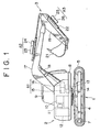
- FIG.1 shows an entire excavator according to this embodiment.
- reference numeral 1 denotes a lower travel body; 2 an upper turning body; and 3 an excavation attachment mounted on the front part of the upper turning body 2.
- the lower travel body 1 comprises left and right crawler frames 4 and crawlers (in both of which, only one side is shown) 5, and both the crawlers 5 travel by being individually rotated and driven by left and right electric motors for traveling (see FIG. 3) 6 and 7.
- the upper turning body 2 comprises a turning frame 8, a cabin 9 and so on.
- an engine 10 as a power source
- a generator 11 driven by the engine 10
- a battery 12 an electric motor for turning 13
- a reduction unit 14 for reducing a turning force of the electric motor for turning 13 to transmit it to a turning mechanism (a turning gear), an electric motor for a boom 15, and a hydraulic pump for a boom (hereinafter referred to as boom pump) 16 rotated and driven by the electric motor for a boom 15.
- boom pump a hydraulic pump for a boom
- the excavation attachment 3 comprises a boom 17, a boom cylinder 18 expanded and contracted the boom 17 by pressure oil from the boom pump 16, an arm 19, an arm cylinder 20 for turning the arm 18, a bucket 21, and a bucket cylinder 22 for operating the bucket 21.
- an electric motor 23 for an arm and a hydraulic pump for an arm (hereinafter referred to as an arm pump) 24 driven thereby, and an electric motor for a bucket 25 and a hydraulic pump for a bucket driven thereby (hereinafter referred to as a bucket pump) 26 are provided on the arm cylinder 20, and the bucket cylinder 22, respectively.
- Units of the electric motor for a boom 15 and the boom pump 16, of the electric motor for an arm 23 and the arm pump 24, and of the electric motor for a bucket 25 and the bucket pump 26 are constituted as well known integrated type actuators A1, A2 and A3, respectively.
- the constitution of the integrated type actuators A1, A2 and A3 is shown in FIG. 2.
- the pumps 16, 24 and 26 are respectively constituted as bi-directional pumps in which an oil discharging direction is converted according to a turning direction of the electric motors 15, 23 and 25, and both discharge ports of the pumps 16, 24 and 26 are connected to oil chambers on the head side and the rod side of the cylinders 18, 20 and 22 through pipes 27 and 28.
- reference numerals 29, 29 denote a relief valve; 30 an oil tank; 31 automatic switching valves provided between the pump 16, 24, 26 and the oil tank 30; 32, 32 operate check valves; 33 manual open-close valves provided between both the pipes 27 and 28; and 34, 34 slow return valves.
- the entire unit can be miniaturized and light-weighted as compared with the case where the electric motor and the pump are separately provided. Therefore, it is advantageously mounted on the excavation attachment 3.
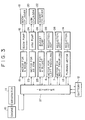
- FIG. 3 shows the block constitution of a driving system and a control system of the excavator.
- the solid line, the dotted line, and the phantom outline indicate an electric driving system, an electric circuit, and a hydraulic driving system, respectively.
- reference numeral 35, 36 denote reduction units for left and right electric motors for traveling 6, 7.
- An inverter 37 is provided between the generator 11, each of the electric motors 6, 7, 15, 23, 25 and a battery 12. By the inverter 37,
- the inverter 37 is provided with a switching means not shown whereby the charging and discharging operations are switched by operation of an operator or according to the load condition.
- the electric motors 6, 7, 15, 23 and 25 are controlled in turning speed and turning direction by, for example, an operating means of a lever operating type not shown which is operated by an operator.
- the generator 11 When the engine 10 is operated, the generator 11 is driven to carry out generating operation, and the electric motors 6, 7, 15, 23 and 25 are driven by AC power generated.
- the electric motors 6, 7, 15, 23, 25 are driven by power supplied via the inverter 37 from the generator 11, but under heavy load, by operation of the switching means, short of power is compensated by the stored power of the battery 12, while under light load, surplus power of the generator 11 is stored in the battery 12.
- the electric motors 6, 7, 15, 23, 25 are operated as a generator (regenerative operation) making use of position energy and kinetic energy thereof whereby the regenerative power generated can be stored in the battery 12.
- the electric motors 15, 23, 25 provided on the excavation attachment 3 are so high in position energy and kinetic energy that the stored effect is high. It is therefore possible to reduce consuming energy and minimize the battery 12.
- the engine load can be smoothed, the noise and exhaust gases can be reduced, and the fuel cost can be reduced.
- the turning force is transmitted through the channel of the engine 10 - generator 11 ...electric motors 6, 7, 15, 23, 25, as described above, the mechanical coupling being merely for the engine 10 and the generator 11.
- the power unit is divided into a set of engine 10 + generator, and the electric motors 6, 7, 15, 23, 25, and the former can be installed on the upper turning body 2 while the latter can be installed on various operating parts (the lower traveling body 1, the upper traveling body 2, and the excavation attachment). Accordingly, since a large installation space collected at one place is not necessary, and this is suited, particularly, for a small turning type excavator.
- various operating parts are driven by the electric motors 6, 7, 15, 23, 25, and the generator 11 can be connected to the electric motors 6, 7, 15, 23, 25 by an electric wiring, thus enabling considerable reduction of transmission loss of energy.
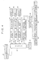
- the second embodiment has paid attention thereto to employ the H second constitution in which a traveling and turning electric motor 40 is used, so that a traveling and turning hydraulic pump 41 is driven by the electric motor 40, and pressure oil from the pump 41 can be supplied to left and right traveling hydraulic motors 43, 44 or a turning hydraulic motor 45 through a switching valve 42 to selectively perform the traveling and turning operation.
- the present invention can be also applied to an excavator wherein in the excavation attachment 3, other working tools (for example, an earth removing plate and a crusher) are mounted in place of the bucket 21, an excavator which as the excavation attachment 3, is provided with a loading type for excavation from this side to the opposite side in place of a back hoe type for excavation toward this side as shown in FIG. 1, and an excavator which uses a wheel in place of a crawler as a lower traveling body.
- other working tools for example, an earth removing plate and a crusher
- the constitution is employed in which the generator is driven by the engine as a driving source, the electric motors are rotated by electric power supplied from the generator, and the lower traveling body and the upper turning body and the operating parts of the excavation attachment are operated by the electric motors, and therefore, only the engine and the generator will suffice for the mechanical connection.
- the power unit is divided into a set of engine + generator and electric motors, which can be installed separately (the former is the upper turning body, and the latter are the operating parts).
- the stored effect is obtained, and particularly, the electric motors provided on the excavation attachment are high in stored effect because position energy and kinetic energy can be used for the regenerative operation.
- the consuming energy can be reduced, and the battery can be miniaturized.
- the traveling hydraulic motor and the turning hydraulic motor are provided on the lower traveling body and the upper turning body, respectively, and oil from oil pressure driven by a single electric motor is selectively supplied to one of the traveling hydraulic motor and the turning hydraulic motor through the switching valve, one electric motor can be used in common for the "traveling" and "turning" which are rarely operated simultaneously.
- the electric motor/pump integrated type actuator is used whereby miniaturization and light-weight construction can be realized as compared with the case where these elements are provided separately and independently. Therefore, this is particularly suitable for one installed on the excavation attachment.
- the installing space for the power unit can be reduced, and there can be obtained the useful effect which is advantageous particularly in the small turning type excavator.
Landscapes
- Engineering & Computer Science (AREA)
- Mechanical Engineering (AREA)
- General Engineering & Computer Science (AREA)
- Structural Engineering (AREA)
- Mining & Mineral Resources (AREA)
- Civil Engineering (AREA)
- Power Engineering (AREA)
- Transportation (AREA)
- Combustion & Propulsion (AREA)
- Chemical & Material Sciences (AREA)
- Fluid Mechanics (AREA)
- Physics & Mathematics (AREA)
- Operation Control Of Excavators (AREA)
- Fluid-Pressure Circuits (AREA)
- Shovels (AREA)
- Electric Propulsion And Braking For Vehicles (AREA)
- Lubricants (AREA)
Claims (6)
- Excavateur dans lequel un corps rotatif supérieur (2) est monté sur un corps mobile inférieur (1), et une fixation d'excavation (3) est prévue sur le corps rotatif supérieur, comprenant
un moteur (10) comme source d'énergie,
un générateur (11) directement raccordé au moteur et entraîné par le moteur pour produire de l'énergie électrique, et
un onduleur (37) raccordé au générateur, via lequel l'énergie électrique est amenée du générateur,
caractérisé par
une pluralité de moteurs électriques (6, 7, 15, 23, 25) raccordés à l'onduleur et alimentés via l'onduleur en énergie électrique afin d'être amenés en rotation, et
une pluralité de pompes hydrauliques (16, 24, 26, 41) exclusivement entraînées par chaque moteur électrique de la pluralité des moteurs électriques,
dans lequel
les moteurs électriques sont prévus en tant que source d'entraînement destinée à faire fonctionner le corps mobile inférieur, le corps rotatif supérieur et chaque partie opérationnelle de la fixation d'excavation et,
dans la partie opérationnelle pourvue d'un actionneur hydraulique (18, 20, 22), ledit actionneur hydraulique est actionné par de l'huile provenant de chaque pompe de ladite pluralité de pompes hydrauliques. - Excavateur selon la revendication 1, dans lequel le surplus d'énergie électrique provenant du générateur est stocké dans une batterie (12), et les moteurs électriques sont entraînés par l'énergie électrique stockée dans la batterie lorsque cela s'avère nécessaire.
- Excavateur selon la revendication 2, dans lequel l'énergie électrique générée par la commande de vitesse par rétroaction des moteurs électriques est stockée dans la batterie.
- Excavateur selon la revendication 1, dans lequel comme l'actionneur hydraulique dans la partie opérationnelle, un moteur hydraulique mobile (43, 44) et un moteur hydraulique rotatif (45) sont prévus sur le corps mobile inférieur et le corps rotatif supérieur, respectivement, et de l'huile provenant de la pompe hydraulique (41) entraînée par un moteur électrique (40) est amenée sélectivement soit au dit moteur hydraulique mobile soit au dit moteur hydraulique rotatif.
- Excavateur selon l'une quelconque des revendications 1 à 4, utilisant un actionneur du type à motopompe électrique intégrée dans lequel le moteur électrique et la pompe hydraulique, dans lequel une direction d'évacuation de l'huile est convertie selon la direction de rotation dudit moteur électrique.
- Excavateur selon l'une quelconque des revendications 1 à 3, dans lequel la force de rotation du moteur électrique est réduite par une unité de réduction (35, 36, 14) pour l'appliquer en tant que force d'entraînement à la partie opérationnelle.
Applications Claiming Priority (3)
| Application Number | Priority Date | Filing Date | Title |
|---|---|---|---|
| JP09317899A JP3877901B2 (ja) | 1999-03-31 | 1999-03-31 | ショベル |
| JP9317899 | 1999-03-31 | ||
| PCT/JP2000/002060 WO2000058569A1 (fr) | 1999-03-31 | 2000-03-31 | Excavatrice |
Publications (3)
| Publication Number | Publication Date |
|---|---|
| EP1126086A1 EP1126086A1 (fr) | 2001-08-22 |
| EP1126086A4 EP1126086A4 (fr) | 2002-07-24 |
| EP1126086B1 true EP1126086B1 (fr) | 2006-01-18 |
Family
ID=14075335
Family Applications (1)
| Application Number | Title | Priority Date | Filing Date |
|---|---|---|---|
| EP00913010A Expired - Lifetime EP1126086B1 (fr) | 1999-03-31 | 2000-03-31 | Excavatrice |
Country Status (7)
| Country | Link |
|---|---|
| US (1) | US6789335B1 (fr) |
| EP (1) | EP1126086B1 (fr) |
| JP (1) | JP3877901B2 (fr) |
| KR (1) | KR20010043922A (fr) |
| AT (1) | ATE316172T1 (fr) |
| DE (1) | DE60025594T2 (fr) |
| WO (1) | WO2000058569A1 (fr) |
Cited By (1)
| Publication number | Priority date | Publication date | Assignee | Title |
|---|---|---|---|---|
| CN102459768B (zh) * | 2009-05-15 | 2015-06-24 | 西门子工业公司 | 限制采矿挖掘机所汲取的峰值电功率 |
Families Citing this family (79)
| Publication number | Priority date | Publication date | Assignee | Title |
|---|---|---|---|---|
| JP4794713B2 (ja) * | 2000-01-28 | 2011-10-19 | 住友建機株式会社 | 電動ショベル |
| JP3859982B2 (ja) * | 2001-04-27 | 2006-12-20 | 株式会社神戸製鋼所 | ハイブリッド建設機械の電力制御装置 |
| JP2002330554A (ja) | 2001-04-27 | 2002-11-15 | Kobelco Contstruction Machinery Ltd | ハイブリッド車両の電力制御装置および当該電力制御装置を備えたハイブリッド建設機械 |
| JP4815703B2 (ja) * | 2001-07-02 | 2011-11-16 | 井関農機株式会社 | トラクタ |
| JP4179465B2 (ja) * | 2002-07-31 | 2008-11-12 | 株式会社小松製作所 | 建設機械 |
| JP2004190845A (ja) * | 2002-12-13 | 2004-07-08 | Shin Caterpillar Mitsubishi Ltd | 作業機械の駆動装置 |
| WO2005021415A1 (fr) * | 2003-08-22 | 2005-03-10 | Terex-Demag Gmbh & Co. Kg | Fleche de grue mobile comportant une unite hydraulique autonome montee sur cette derniere |
| JP2006348978A (ja) * | 2005-06-13 | 2006-12-28 | Sumitomo (Shi) Construction Machinery Manufacturing Co Ltd | 作業機械の駆動装置 |
| KR100662556B1 (ko) * | 2005-10-19 | 2007-01-02 | 디엠씨(주) | 전동식 버켓크레인 |
| JP4529866B2 (ja) * | 2005-10-27 | 2010-08-25 | コベルコ建機株式会社 | ハイブリッド式建設機械 |
| US7487023B2 (en) | 2005-10-27 | 2009-02-03 | Kobelco Construction Machinery Co., Ltd. | Construction machine |
| JP2008008094A (ja) * | 2006-06-30 | 2008-01-17 | Hitachi Constr Mach Co Ltd | 建設機械 |
| JP5055948B2 (ja) * | 2006-10-20 | 2012-10-24 | コベルコ建機株式会社 | ハイブリッド作業機械 |
| JP2008121659A (ja) * | 2006-10-20 | 2008-05-29 | Kobelco Contstruction Machinery Ltd | ハイブリッド作業機械 |
| US20110064706A1 (en) * | 2008-01-11 | 2011-03-17 | U.S. Nutraceuticals, Llc D/B/A Valensa International | Method of preventing, controlling and ameliorating urinary tract infections and supporting digestive health by using a synergistic cranberry derivative, a d-mannose composition and a proprietary probiotic blend |
| US7992370B2 (en) | 2008-03-14 | 2011-08-09 | Deere & Company | Work machine with auxiliary power unit and intelligent power management |
| JP4609567B2 (ja) | 2008-10-29 | 2011-01-12 | コベルコ建機株式会社 | ハイブリッド作業機械 |
| EP2429871B1 (fr) * | 2009-05-12 | 2013-02-20 | El-Forest AB | Système énergétique pour véhicule hybride |
| US8087900B2 (en) * | 2009-05-22 | 2012-01-03 | Deere & Company | Agricultural harvester with propulsion load shifting between dual engines |
| US7974757B2 (en) * | 2009-05-22 | 2011-07-05 | Deere & Company | Agricultural harvester with dual engine failure power transfer system |
| JP5163593B2 (ja) * | 2009-05-25 | 2013-03-13 | コベルコ建機株式会社 | ハイブリッド作業機械 |
| JP5338479B2 (ja) * | 2009-05-25 | 2013-11-13 | コベルコ建機株式会社 | ハイブリッド作業機械 |
| US20110056194A1 (en) * | 2009-09-10 | 2011-03-10 | Bucyrus International, Inc. | Hydraulic system for heavy equipment |
| US20110056192A1 (en) * | 2009-09-10 | 2011-03-10 | Robert Weber | Technique for controlling pumps in a hydraulic system |
| US8362629B2 (en) * | 2010-03-23 | 2013-01-29 | Bucyrus International Inc. | Energy management system for heavy equipment |
| US20130038121A1 (en) * | 2010-04-28 | 2013-02-14 | Nabtesco Corporation | Hybrid Construction Machine Control System |
| JP5600274B2 (ja) * | 2010-08-18 | 2014-10-01 | 川崎重工業株式会社 | 作業機械の電液駆動システム |
| JP5699155B2 (ja) * | 2010-09-21 | 2015-04-08 | 株式会社竹内製作所 | 旋回駆動制御装置 |
| US8626403B2 (en) * | 2010-10-06 | 2014-01-07 | Caterpillar Global Mining Llc | Energy management and storage system |
| US8718845B2 (en) | 2010-10-06 | 2014-05-06 | Caterpillar Global Mining Llc | Energy management system for heavy equipment |
| US8606451B2 (en) | 2010-10-06 | 2013-12-10 | Caterpillar Global Mining Llc | Energy system for heavy equipment |
| CN103298671B (zh) * | 2010-12-27 | 2016-03-16 | 沃尔沃建造设备有限公司 | 用于控制根据混合动力挖掘机的负载的动力的装置和方法 |
| CN102071718B (zh) * | 2011-03-01 | 2012-11-14 | 山河智能装备股份有限公司 | 挖掘机能量回收系统 |
| JP5685140B2 (ja) * | 2011-05-13 | 2015-03-18 | 川崎重工業株式会社 | 巻上装置用液圧回路及びそれを備える巻上装置 |
| US8944103B2 (en) | 2011-08-31 | 2015-02-03 | Caterpillar Inc. | Meterless hydraulic system having displacement control valve |
| US8863509B2 (en) | 2011-08-31 | 2014-10-21 | Caterpillar Inc. | Meterless hydraulic system having load-holding bypass |
| US8966892B2 (en) | 2011-08-31 | 2015-03-03 | Caterpillar Inc. | Meterless hydraulic system having restricted primary makeup |
| US9057389B2 (en) | 2011-09-30 | 2015-06-16 | Caterpillar Inc. | Meterless hydraulic system having multi-actuator circuit |
| US8966891B2 (en) | 2011-09-30 | 2015-03-03 | Caterpillar Inc. | Meterless hydraulic system having pump protection |
| US9151018B2 (en) | 2011-09-30 | 2015-10-06 | Caterpillar Inc. | Closed-loop hydraulic system having energy recovery |
| US9051714B2 (en) | 2011-09-30 | 2015-06-09 | Caterpillar Inc. | Meterless hydraulic system having multi-actuator circuit |
| US8984873B2 (en) | 2011-10-21 | 2015-03-24 | Caterpillar Inc. | Meterless hydraulic system having flow sharing and combining functionality |
| US8943819B2 (en) | 2011-10-21 | 2015-02-03 | Caterpillar Inc. | Hydraulic system |
| US8919114B2 (en) | 2011-10-21 | 2014-12-30 | Caterpillar Inc. | Closed-loop hydraulic system having priority-based sharing |
| US8973358B2 (en) | 2011-10-21 | 2015-03-10 | Caterpillar Inc. | Closed-loop hydraulic system having force modulation |
| US8910474B2 (en) | 2011-10-21 | 2014-12-16 | Caterpillar Inc. | Hydraulic system |
| US8978374B2 (en) | 2011-10-21 | 2015-03-17 | Caterpillar Inc. | Meterless hydraulic system having flow sharing and combining functionality |
| US8893490B2 (en) | 2011-10-21 | 2014-11-25 | Caterpillar Inc. | Hydraulic system |
| US8978373B2 (en) | 2011-10-21 | 2015-03-17 | Caterpillar Inc. | Meterless hydraulic system having flow sharing and combining functionality |
| US9080310B2 (en) | 2011-10-21 | 2015-07-14 | Caterpillar Inc. | Closed-loop hydraulic system having regeneration configuration |
| US9068578B2 (en) | 2011-10-21 | 2015-06-30 | Caterpillar Inc. | Hydraulic system having flow combining capabilities |
| JP5970898B2 (ja) * | 2012-03-26 | 2016-08-17 | コベルコ建機株式会社 | 動力伝達装置及びこれを備えたハイブリッド建設機械 |
| US9279236B2 (en) | 2012-06-04 | 2016-03-08 | Caterpillar Inc. | Electro-hydraulic system for recovering and reusing potential energy |
| JP6019956B2 (ja) * | 2012-09-06 | 2016-11-02 | コベルコ建機株式会社 | ハイブリッド建設機械の動力制御装置 |
| US9190852B2 (en) | 2012-09-21 | 2015-11-17 | Caterpillar Global Mining Llc | Systems and methods for stabilizing power rate of change within generator based applications |
| US20150284933A1 (en) * | 2012-10-29 | 2015-10-08 | Volvo Construction Equipment Ab | Electro hydraulic actuator mounting structure for hybrid type construction machine |
| US9290912B2 (en) | 2012-10-31 | 2016-03-22 | Caterpillar Inc. | Energy recovery system having integrated boom/swing circuits |
| JP6051857B2 (ja) * | 2012-12-28 | 2016-12-27 | コベルコ建機株式会社 | 建設機械 |
| EP2951359B1 (fr) | 2013-01-30 | 2017-10-04 | Parker Hannifin Corporation | Système d'entraînement à bascule hybride hydraulique pour excavateurs |
| US9290911B2 (en) | 2013-02-19 | 2016-03-22 | Caterpillar Inc. | Energy recovery system for hydraulic machine |
| JP6232795B2 (ja) | 2013-07-18 | 2017-11-22 | コベルコ建機株式会社 | ハイブリッド建設機械 |
| US9441347B2 (en) | 2013-08-05 | 2016-09-13 | Deere & Company | Methods and apparatus to control a dual function work machine |
| US9484602B1 (en) | 2013-08-22 | 2016-11-01 | OSC Manufacturing & Equipment Services, Inc. | Light tower having a battery housing |
| JP6197527B2 (ja) * | 2013-09-24 | 2017-09-20 | コベルコ建機株式会社 | ハイブリッド建設機械 |
| WO2016097784A1 (fr) * | 2014-12-16 | 2016-06-23 | Volvo Construction Equipment Ab | Bras d'excavateur, élément en porte-à-faux d'excavateur comprenant un tel bras d'excavateur et excavateur comprenant un tel élément en porte-à-faux d'excavateur |
| EP3037293B1 (fr) | 2014-12-22 | 2017-08-09 | Sennebogen Maschinenfabrik GmbH | Machine-outil automobile |
| US10458095B2 (en) | 2015-01-07 | 2019-10-29 | Volvo Construction Equipment Ab | Control method for controlling an excavator and excavator comprising a control unit implementing such a control method |
| US10749224B2 (en) | 2015-08-17 | 2020-08-18 | OSC Manufacturing & Equipment Services, Inc. | Rechargeable battery power system having a battery with multiple uses |
| JP2020029237A (ja) * | 2018-08-24 | 2020-02-27 | ヤンマー株式会社 | ハイブリッド建設機械 |
| US11511642B2 (en) | 2019-04-05 | 2022-11-29 | Oshkosh Corporation | Electric concrete vehicle systems and methods |
| US10981024B1 (en) | 2019-10-11 | 2021-04-20 | Oshkosh Corporation | Hybrid fire fighting vehicle |
| JP7405582B2 (ja) * | 2019-12-03 | 2023-12-26 | ナブテスコ株式会社 | 作用部用減速部及び建設機械 |
| CN111021462A (zh) * | 2019-12-31 | 2020-04-17 | 三一重机有限公司 | 一种串联式混合动力挖掘机控制系统及其控制方法 |
| CN115427701B (zh) * | 2020-05-01 | 2025-09-23 | 康明斯公司 | 用于多功能机器的分布式泵架构 |
| KR102913376B1 (ko) * | 2020-06-12 | 2026-01-14 | 에이치디현대인프라코어 주식회사 | 건설 기계 |
| CN113463701A (zh) * | 2021-03-12 | 2021-10-01 | 北京理工大学 | 一种基于力矩电机的无液压混合动力挖掘机 |
| EP4592458A4 (fr) * | 2022-10-17 | 2026-01-21 | Hd Hyundai Infracore Co Ltd | Excavatrice électrique |
| EP4567196A1 (fr) | 2023-12-05 | 2025-06-11 | Volvo Construction Equipment AB | Équipement de construction |
| CN118407478B (zh) * | 2024-06-25 | 2025-12-09 | 江苏徐工工程机械研究院有限公司 | 装载机及其控制方法 |
Family Cites Families (11)
| Publication number | Priority date | Publication date | Assignee | Title |
|---|---|---|---|---|
| US4193733A (en) * | 1978-05-17 | 1980-03-18 | Harnischfeger Corporation | Hydraulic excavator machine having self-contained electrohydraulic power units |
| EP0116474B1 (fr) * | 1983-02-12 | 1986-12-10 | Kabushiki Kaisha Hikoma Seisakusho | Engin de terrassement |
| JPS63300131A (ja) * | 1987-05-30 | 1988-12-07 | Shin Caterpillar Mitsubishi Ltd | 電気パワ−ショベル |
| JP2916380B2 (ja) * | 1994-08-18 | 1999-07-05 | 新キャタピラー三菱株式会社 | 建設機械のパワーユニット制御方法およびその装置 |
| US5957989A (en) * | 1996-01-22 | 1999-09-28 | Hitachi Construction Machinery Co. Ltd. | Interference preventing system for construction machine |
| JPH101978A (ja) * | 1996-06-13 | 1998-01-06 | Yutani Heavy Ind Ltd | バッテリ駆動の作業機械 |
| JPH10103112A (ja) * | 1996-09-26 | 1998-04-21 | Daikin Ind Ltd | 油圧駆動装置 |
| JPH10152865A (ja) * | 1996-11-22 | 1998-06-09 | Yutani Heavy Ind Ltd | バッテリ駆動の作業機械 |
| JPH10281263A (ja) * | 1997-04-09 | 1998-10-23 | Hitachi Constr Mach Co Ltd | 遊星歯車減速装置 |
| JPH10306466A (ja) * | 1997-04-30 | 1998-11-17 | Hitachi Constr Mach Co Ltd | 旋回式建設機械 |
| JPH11343642A (ja) * | 1998-06-01 | 1999-12-14 | Kobe Steel Ltd | バッテリー駆動式作業機械 |
-
1999
- 1999-03-31 JP JP09317899A patent/JP3877901B2/ja not_active Expired - Fee Related
-
2000
- 2000-03-31 WO PCT/JP2000/002060 patent/WO2000058569A1/fr not_active Ceased
- 2000-03-31 KR KR1020007013455A patent/KR20010043922A/ko not_active Ceased
- 2000-03-31 US US09/700,729 patent/US6789335B1/en not_active Expired - Fee Related
- 2000-03-31 EP EP00913010A patent/EP1126086B1/fr not_active Expired - Lifetime
- 2000-03-31 DE DE60025594T patent/DE60025594T2/de not_active Expired - Lifetime
- 2000-03-31 AT AT00913010T patent/ATE316172T1/de not_active IP Right Cessation
Cited By (1)
| Publication number | Priority date | Publication date | Assignee | Title |
|---|---|---|---|---|
| CN102459768B (zh) * | 2009-05-15 | 2015-06-24 | 西门子工业公司 | 限制采矿挖掘机所汲取的峰值电功率 |
Also Published As
| Publication number | Publication date |
|---|---|
| JP2000283107A (ja) | 2000-10-13 |
| KR20010043922A (ko) | 2001-05-25 |
| JP3877901B2 (ja) | 2007-02-07 |
| US6789335B1 (en) | 2004-09-14 |
| WO2000058569A1 (fr) | 2000-10-05 |
| EP1126086A4 (fr) | 2002-07-24 |
| EP1126086A1 (fr) | 2001-08-22 |
| DE60025594T2 (de) | 2006-11-16 |
| ATE316172T1 (de) | 2006-02-15 |
| DE60025594D1 (de) | 2006-04-06 |
Similar Documents
| Publication | Publication Date | Title |
|---|---|---|
| EP1126086B1 (fr) | Excavatrice | |
| EP1191155B1 (fr) | Excavatrice avec un dispositif de commande hybride | |
| JP5180518B2 (ja) | ハイブリッド型駆動装置を備えた建設機械 | |
| JP3647319B2 (ja) | 油圧駆動装置 | |
| CN102301583B (zh) | 混合式工作机械及伺服控制系统 | |
| KR100517849B1 (ko) | 건설 기계 | |
| US8347998B2 (en) | Working machine with one or more electric machines for driving, braking, and/or generating power and a method for operating such a working machine | |
| WO2007138862A1 (fr) | Véhicule de travail | |
| US20050036894A1 (en) | Construction machine | |
| EP1199411B1 (fr) | Excavatrice | |
| EP3594413B1 (fr) | Architecture de puissance pour un véhicule tel qu'un véhicule tout terrain | |
| EP1937904B1 (fr) | Machine de travail | |
| US20040000141A1 (en) | Hydraulic energy recovering/regenerating apparatus | |
| JP2001329573A (ja) | 建設機械 | |
| JP2003049810A (ja) | 圧油のエネルギー回収装置および圧油のエネルギー回収装置を備えた建設機械 | |
| JP2001012404A (ja) | ハイブリッド建設機械 | |
| JP2001016891A (ja) | 建設機械 | |
| EP3951086B1 (fr) | Excavatrice | |
| US20240301654A1 (en) | Working vehicle | |
| JP5318329B2 (ja) | ハイブリッド型建設機械の駆動装置 | |
| JP2002322682A (ja) | ショベル | |
| JP5399105B2 (ja) | ハイブリッド式作業機械 | |
| JP2002105985A (ja) | ショベル | |
| JP4455297B2 (ja) | 建設機械の駆動装置 | |
| JP7063835B2 (ja) | 作業機械 |
Legal Events
| Date | Code | Title | Description |
|---|---|---|---|
| PUAI | Public reference made under article 153(3) epc to a published international application that has entered the european phase |
Free format text: ORIGINAL CODE: 0009012 |
|
| 17P | Request for examination filed |
Effective date: 20001109 |
|
| AK | Designated contracting states |
Kind code of ref document: A1 Designated state(s): AT BE CH CY DE DK ES FI FR GB GR IE IT LI LU MC NL PT SE |
|
| A4 | Supplementary search report drawn up and despatched |
Effective date: 20020606 |
|
| AK | Designated contracting states |
Kind code of ref document: A4 Designated state(s): AT BE CH CY DE DK ES FI FR GB GR IE IT LI LU MC NL PT SE |
|
| 17Q | First examination report despatched |
Effective date: 20021128 |
|
| RTI1 | Title (correction) |
Free format text: EXCAVATOR |
|
| GRAP | Despatch of communication of intention to grant a patent |
Free format text: ORIGINAL CODE: EPIDOSNIGR1 |
|
| GRAS | Grant fee paid |
Free format text: ORIGINAL CODE: EPIDOSNIGR3 |
|
| GRAA | (expected) grant |
Free format text: ORIGINAL CODE: 0009210 |
|
| AK | Designated contracting states |
Kind code of ref document: B1 Designated state(s): AT BE CH CY DE DK ES FI FR GB GR IE IT LI LU MC NL PT SE |
|
| PG25 | Lapsed in a contracting state [announced via postgrant information from national office to epo] |
Ref country code: AT Free format text: LAPSE BECAUSE OF FAILURE TO SUBMIT A TRANSLATION OF THE DESCRIPTION OR TO PAY THE FEE WITHIN THE PRESCRIBED TIME-LIMIT Effective date: 20060118 Ref country code: CH Free format text: LAPSE BECAUSE OF FAILURE TO SUBMIT A TRANSLATION OF THE DESCRIPTION OR TO PAY THE FEE WITHIN THE PRESCRIBED TIME-LIMIT Effective date: 20060118 Ref country code: LI Free format text: LAPSE BECAUSE OF FAILURE TO SUBMIT A TRANSLATION OF THE DESCRIPTION OR TO PAY THE FEE WITHIN THE PRESCRIBED TIME-LIMIT Effective date: 20060118 Ref country code: FI Free format text: LAPSE BECAUSE OF FAILURE TO SUBMIT A TRANSLATION OF THE DESCRIPTION OR TO PAY THE FEE WITHIN THE PRESCRIBED TIME-LIMIT Effective date: 20060118 Ref country code: NL Free format text: LAPSE BECAUSE OF FAILURE TO SUBMIT A TRANSLATION OF THE DESCRIPTION OR TO PAY THE FEE WITHIN THE PRESCRIBED TIME-LIMIT Effective date: 20060118 Ref country code: BE Free format text: LAPSE BECAUSE OF FAILURE TO SUBMIT A TRANSLATION OF THE DESCRIPTION OR TO PAY THE FEE WITHIN THE PRESCRIBED TIME-LIMIT Effective date: 20060118 |
|
| REG | Reference to a national code |
Ref country code: GB Ref legal event code: FG4D |
|
| REG | Reference to a national code |
Ref country code: CH Ref legal event code: EP |
|
| REG | Reference to a national code |
Ref country code: IE Ref legal event code: FG4D |
|
| PG25 | Lapsed in a contracting state [announced via postgrant information from national office to epo] |
Ref country code: IE Free format text: LAPSE BECAUSE OF NON-PAYMENT OF DUE FEES Effective date: 20060331 Ref country code: LU Free format text: LAPSE BECAUSE OF NON-PAYMENT OF DUE FEES Effective date: 20060331 Ref country code: MC Free format text: LAPSE BECAUSE OF NON-PAYMENT OF DUE FEES Effective date: 20060331 |
|
| REF | Corresponds to: |
Ref document number: 60025594 Country of ref document: DE Date of ref document: 20060406 Kind code of ref document: P |
|
| PG25 | Lapsed in a contracting state [announced via postgrant information from national office to epo] |
Ref country code: SE Free format text: LAPSE BECAUSE OF FAILURE TO SUBMIT A TRANSLATION OF THE DESCRIPTION OR TO PAY THE FEE WITHIN THE PRESCRIBED TIME-LIMIT Effective date: 20060418 Ref country code: DK Free format text: LAPSE BECAUSE OF FAILURE TO SUBMIT A TRANSLATION OF THE DESCRIPTION OR TO PAY THE FEE WITHIN THE PRESCRIBED TIME-LIMIT Effective date: 20060418 |
|
| PG25 | Lapsed in a contracting state [announced via postgrant information from national office to epo] |
Ref country code: ES Free format text: LAPSE BECAUSE OF FAILURE TO SUBMIT A TRANSLATION OF THE DESCRIPTION OR TO PAY THE FEE WITHIN THE PRESCRIBED TIME-LIMIT Effective date: 20060429 |
|
| PG25 | Lapsed in a contracting state [announced via postgrant information from national office to epo] |
Ref country code: PT Free format text: LAPSE BECAUSE OF FAILURE TO SUBMIT A TRANSLATION OF THE DESCRIPTION OR TO PAY THE FEE WITHIN THE PRESCRIBED TIME-LIMIT Effective date: 20060619 |
|
| NLV1 | Nl: lapsed or annulled due to failure to fulfill the requirements of art. 29p and 29m of the patents act | ||
| ET | Fr: translation filed | ||
| REG | Reference to a national code |
Ref country code: CH Ref legal event code: PL |
|
| PLBE | No opposition filed within time limit |
Free format text: ORIGINAL CODE: 0009261 |
|
| STAA | Information on the status of an ep patent application or granted ep patent |
Free format text: STATUS: NO OPPOSITION FILED WITHIN TIME LIMIT |
|
| 26N | No opposition filed |
Effective date: 20061019 |
|
| PG25 | Lapsed in a contracting state [announced via postgrant information from national office to epo] |
Ref country code: GR Free format text: LAPSE BECAUSE OF FAILURE TO SUBMIT A TRANSLATION OF THE DESCRIPTION OR TO PAY THE FEE WITHIN THE PRESCRIBED TIME-LIMIT Effective date: 20060419 |
|
| PG25 | Lapsed in a contracting state [announced via postgrant information from national office to epo] |
Ref country code: CY Free format text: LAPSE BECAUSE OF FAILURE TO SUBMIT A TRANSLATION OF THE DESCRIPTION OR TO PAY THE FEE WITHIN THE PRESCRIBED TIME-LIMIT Effective date: 20060118 |
|
| PGFP | Annual fee paid to national office [announced via postgrant information from national office to epo] |
Ref country code: IT Payment date: 20120320 Year of fee payment: 13 |
|
| PGFP | Annual fee paid to national office [announced via postgrant information from national office to epo] |
Ref country code: GB Payment date: 20130327 Year of fee payment: 14 Ref country code: FR Payment date: 20130325 Year of fee payment: 14 Ref country code: DE Payment date: 20130327 Year of fee payment: 14 |
|
| REG | Reference to a national code |
Ref country code: DE Ref legal event code: R119 Ref document number: 60025594 Country of ref document: DE |
|
| GBPC | Gb: european patent ceased through non-payment of renewal fee |
Effective date: 20140331 |
|
| REG | Reference to a national code |
Ref country code: DE Ref legal event code: R119 Ref document number: 60025594 Country of ref document: DE Effective date: 20141001 |
|
| REG | Reference to a national code |
Ref country code: FR Ref legal event code: ST Effective date: 20141128 |
|
| PG25 | Lapsed in a contracting state [announced via postgrant information from national office to epo] |
Ref country code: FR Free format text: LAPSE BECAUSE OF NON-PAYMENT OF DUE FEES Effective date: 20140331 Ref country code: GB Free format text: LAPSE BECAUSE OF NON-PAYMENT OF DUE FEES Effective date: 20140331 Ref country code: DE Free format text: LAPSE BECAUSE OF NON-PAYMENT OF DUE FEES Effective date: 20141001 |
|
| PG25 | Lapsed in a contracting state [announced via postgrant information from national office to epo] |
Ref country code: IT Free format text: LAPSE BECAUSE OF NON-PAYMENT OF DUE FEES Effective date: 20140331 |