EP1126520A2 - IC-Vorrichtung und Methode zur Herstellung - Google Patents
IC-Vorrichtung und Methode zur Herstellung Download PDFInfo
- Publication number
- EP1126520A2 EP1126520A2 EP01102524A EP01102524A EP1126520A2 EP 1126520 A2 EP1126520 A2 EP 1126520A2 EP 01102524 A EP01102524 A EP 01102524A EP 01102524 A EP01102524 A EP 01102524A EP 1126520 A2 EP1126520 A2 EP 1126520A2
- Authority
- EP
- European Patent Office
- Prior art keywords
- resin
- integrated circuit
- metal
- semiconductor integrated
- circuit device
- Prior art date
- Legal status (The legal status is an assumption and is not a legal conclusion. Google has not performed a legal analysis and makes no representation as to the accuracy of the status listed.)
- Withdrawn
Links
Images


Classifications
-
- H—ELECTRICITY
- H10—SEMICONDUCTOR DEVICES; ELECTRIC SOLID-STATE DEVICES NOT OTHERWISE PROVIDED FOR
- H10W—GENERIC PACKAGES, INTERCONNECTIONS, CONNECTORS OR OTHER CONSTRUCTIONAL DETAILS OF DEVICES COVERED BY CLASS H10
- H10W70/00—Package substrates; Interposers; Redistribution layers [RDL]
- H10W70/40—Leadframes
- H10W70/456—Materials
- H10W70/457—Materials of metallic layers on leadframes
-
- H—ELECTRICITY
- H10—SEMICONDUCTOR DEVICES; ELECTRIC SOLID-STATE DEVICES NOT OTHERWISE PROVIDED FOR
- H10W—GENERIC PACKAGES, INTERCONNECTIONS, CONNECTORS OR OTHER CONSTRUCTIONAL DETAILS OF DEVICES COVERED BY CLASS H10
- H10W72/00—Interconnections or connectors in packages
-
- H—ELECTRICITY
- H10—SEMICONDUCTOR DEVICES; ELECTRIC SOLID-STATE DEVICES NOT OTHERWISE PROVIDED FOR
- H10W—GENERIC PACKAGES, INTERCONNECTIONS, CONNECTORS OR OTHER CONSTRUCTIONAL DETAILS OF DEVICES COVERED BY CLASS H10
- H10W72/00—Interconnections or connectors in packages
- H10W72/01—Manufacture or treatment
- H10W72/011—Apparatus therefor
- H10W72/0113—Apparatus for manufacturing die-attach connectors
-
- H—ELECTRICITY
- H10—SEMICONDUCTOR DEVICES; ELECTRIC SOLID-STATE DEVICES NOT OTHERWISE PROVIDED FOR
- H10W—GENERIC PACKAGES, INTERCONNECTIONS, CONNECTORS OR OTHER CONSTRUCTIONAL DETAILS OF DEVICES COVERED BY CLASS H10
- H10W72/00—Interconnections or connectors in packages
- H10W72/01—Manufacture or treatment
- H10W72/013—Manufacture or treatment of die-attach connectors
-
- H—ELECTRICITY
- H10—SEMICONDUCTOR DEVICES; ELECTRIC SOLID-STATE DEVICES NOT OTHERWISE PROVIDED FOR
- H10W—GENERIC PACKAGES, INTERCONNECTIONS, CONNECTORS OR OTHER CONSTRUCTIONAL DETAILS OF DEVICES COVERED BY CLASS H10
- H10W72/00—Interconnections or connectors in packages
- H10W72/071—Connecting or disconnecting
- H10W72/0711—Apparatus therefor
- H10W72/07141—Means for applying energy, e.g. ovens or lasers
-
- H—ELECTRICITY
- H10—SEMICONDUCTOR DEVICES; ELECTRIC SOLID-STATE DEVICES NOT OTHERWISE PROVIDED FOR
- H10W—GENERIC PACKAGES, INTERCONNECTIONS, CONNECTORS OR OTHER CONSTRUCTIONAL DETAILS OF DEVICES COVERED BY CLASS H10
- H10W72/00—Interconnections or connectors in packages
- H10W72/071—Connecting or disconnecting
- H10W72/073—Connecting or disconnecting of die-attach connectors
- H10W72/07331—Connecting techniques
- H10W72/07336—Soldering or alloying
-
- H—ELECTRICITY
- H10—SEMICONDUCTOR DEVICES; ELECTRIC SOLID-STATE DEVICES NOT OTHERWISE PROVIDED FOR
- H10W—GENERIC PACKAGES, INTERCONNECTIONS, CONNECTORS OR OTHER CONSTRUCTIONAL DETAILS OF DEVICES COVERED BY CLASS H10
- H10W72/00—Interconnections or connectors in packages
- H10W72/071—Connecting or disconnecting
- H10W72/073—Connecting or disconnecting of die-attach connectors
- H10W72/07351—Connecting or disconnecting of die-attach connectors characterised by changes in properties of the die-attach connectors during connecting
- H10W72/07352—Connecting or disconnecting of die-attach connectors characterised by changes in properties of the die-attach connectors during connecting changes in structures or sizes
-
- H—ELECTRICITY
- H10—SEMICONDUCTOR DEVICES; ELECTRIC SOLID-STATE DEVICES NOT OTHERWISE PROVIDED FOR
- H10W—GENERIC PACKAGES, INTERCONNECTIONS, CONNECTORS OR OTHER CONSTRUCTIONAL DETAILS OF DEVICES COVERED BY CLASS H10
- H10W72/00—Interconnections or connectors in packages
- H10W72/071—Connecting or disconnecting
- H10W72/075—Connecting or disconnecting of bond wires
- H10W72/07521—Aligning
-
- H—ELECTRICITY
- H10—SEMICONDUCTOR DEVICES; ELECTRIC SOLID-STATE DEVICES NOT OTHERWISE PROVIDED FOR
- H10W—GENERIC PACKAGES, INTERCONNECTIONS, CONNECTORS OR OTHER CONSTRUCTIONAL DETAILS OF DEVICES COVERED BY CLASS H10
- H10W72/00—Interconnections or connectors in packages
- H10W72/071—Connecting or disconnecting
- H10W72/075—Connecting or disconnecting of bond wires
- H10W72/07531—Techniques
- H10W72/07532—Compression bonding, e.g. thermocompression bonding
- H10W72/07533—Ultrasonic bonding, e.g. thermosonic bonding
-
- H—ELECTRICITY
- H10—SEMICONDUCTOR DEVICES; ELECTRIC SOLID-STATE DEVICES NOT OTHERWISE PROVIDED FOR
- H10W—GENERIC PACKAGES, INTERCONNECTIONS, CONNECTORS OR OTHER CONSTRUCTIONAL DETAILS OF DEVICES COVERED BY CLASS H10
- H10W72/00—Interconnections or connectors in packages
- H10W72/071—Connecting or disconnecting
- H10W72/075—Connecting or disconnecting of bond wires
- H10W72/07551—Connecting or disconnecting of bond wires characterised by changes in properties of the bond wires during the connecting
-
- H—ELECTRICITY
- H10—SEMICONDUCTOR DEVICES; ELECTRIC SOLID-STATE DEVICES NOT OTHERWISE PROVIDED FOR
- H10W—GENERIC PACKAGES, INTERCONNECTIONS, CONNECTORS OR OTHER CONSTRUCTIONAL DETAILS OF DEVICES COVERED BY CLASS H10
- H10W72/00—Interconnections or connectors in packages
- H10W72/30—Die-attach connectors
- H10W72/321—Structures or relative sizes of die-attach connectors
- H10W72/325—Die-attach connectors having a filler embedded in a matrix
-
- H—ELECTRICITY
- H10—SEMICONDUCTOR DEVICES; ELECTRIC SOLID-STATE DEVICES NOT OTHERWISE PROVIDED FOR
- H10W—GENERIC PACKAGES, INTERCONNECTIONS, CONNECTORS OR OTHER CONSTRUCTIONAL DETAILS OF DEVICES COVERED BY CLASS H10
- H10W72/00—Interconnections or connectors in packages
- H10W72/30—Die-attach connectors
- H10W72/351—Materials of die-attach connectors
- H10W72/352—Materials of die-attach connectors comprising metals or metalloids, e.g. solders
-
- H—ELECTRICITY
- H10—SEMICONDUCTOR DEVICES; ELECTRIC SOLID-STATE DEVICES NOT OTHERWISE PROVIDED FOR
- H10W—GENERIC PACKAGES, INTERCONNECTIONS, CONNECTORS OR OTHER CONSTRUCTIONAL DETAILS OF DEVICES COVERED BY CLASS H10
- H10W72/00—Interconnections or connectors in packages
- H10W72/30—Die-attach connectors
- H10W72/351—Materials of die-attach connectors
- H10W72/353—Materials of die-attach connectors not comprising solid metals or solid metalloids, e.g. ceramics
- H10W72/354—Materials of die-attach connectors not comprising solid metals or solid metalloids, e.g. ceramics comprising polymers
-
- H—ELECTRICITY
- H10—SEMICONDUCTOR DEVICES; ELECTRIC SOLID-STATE DEVICES NOT OTHERWISE PROVIDED FOR
- H10W—GENERIC PACKAGES, INTERCONNECTIONS, CONNECTORS OR OTHER CONSTRUCTIONAL DETAILS OF DEVICES COVERED BY CLASS H10
- H10W72/00—Interconnections or connectors in packages
- H10W72/50—Bond wires
-
- H—ELECTRICITY
- H10—SEMICONDUCTOR DEVICES; ELECTRIC SOLID-STATE DEVICES NOT OTHERWISE PROVIDED FOR
- H10W—GENERIC PACKAGES, INTERCONNECTIONS, CONNECTORS OR OTHER CONSTRUCTIONAL DETAILS OF DEVICES COVERED BY CLASS H10
- H10W72/00—Interconnections or connectors in packages
- H10W72/50—Bond wires
- H10W72/531—Shapes of wire connectors
- H10W72/536—Shapes of wire connectors the connected ends being ball-shaped
-
- H—ELECTRICITY
- H10—SEMICONDUCTOR DEVICES; ELECTRIC SOLID-STATE DEVICES NOT OTHERWISE PROVIDED FOR
- H10W—GENERIC PACKAGES, INTERCONNECTIONS, CONNECTORS OR OTHER CONSTRUCTIONAL DETAILS OF DEVICES COVERED BY CLASS H10
- H10W72/00—Interconnections or connectors in packages
- H10W72/50—Bond wires
- H10W72/531—Shapes of wire connectors
- H10W72/5363—Shapes of wire connectors the connected ends being wedge-shaped
-
- H—ELECTRICITY
- H10—SEMICONDUCTOR DEVICES; ELECTRIC SOLID-STATE DEVICES NOT OTHERWISE PROVIDED FOR
- H10W—GENERIC PACKAGES, INTERCONNECTIONS, CONNECTORS OR OTHER CONSTRUCTIONAL DETAILS OF DEVICES COVERED BY CLASS H10
- H10W72/00—Interconnections or connectors in packages
- H10W72/50—Bond wires
- H10W72/541—Dispositions of bond wires
- H10W72/5449—Dispositions of bond wires not being orthogonal to a side surface of the chip, e.g. fan-out arrangements
-
- H—ELECTRICITY
- H10—SEMICONDUCTOR DEVICES; ELECTRIC SOLID-STATE DEVICES NOT OTHERWISE PROVIDED FOR
- H10W—GENERIC PACKAGES, INTERCONNECTIONS, CONNECTORS OR OTHER CONSTRUCTIONAL DETAILS OF DEVICES COVERED BY CLASS H10
- H10W72/00—Interconnections or connectors in packages
- H10W72/50—Bond wires
- H10W72/551—Materials of bond wires
- H10W72/552—Materials of bond wires comprising metals or metalloids, e.g. silver
- H10W72/5522—Materials of bond wires comprising metals or metalloids, e.g. silver comprising gold [Au]
-
- H—ELECTRICITY
- H10—SEMICONDUCTOR DEVICES; ELECTRIC SOLID-STATE DEVICES NOT OTHERWISE PROVIDED FOR
- H10W—GENERIC PACKAGES, INTERCONNECTIONS, CONNECTORS OR OTHER CONSTRUCTIONAL DETAILS OF DEVICES COVERED BY CLASS H10
- H10W72/00—Interconnections or connectors in packages
- H10W72/50—Bond wires
- H10W72/59—Bond pads specially adapted therefor
-
- H—ELECTRICITY
- H10—SEMICONDUCTOR DEVICES; ELECTRIC SOLID-STATE DEVICES NOT OTHERWISE PROVIDED FOR
- H10W—GENERIC PACKAGES, INTERCONNECTIONS, CONNECTORS OR OTHER CONSTRUCTIONAL DETAILS OF DEVICES COVERED BY CLASS H10
- H10W72/00—Interconnections or connectors in packages
- H10W72/851—Dispositions of multiple connectors or interconnections
- H10W72/874—On different surfaces
- H10W72/884—Die-attach connectors and bond wires
-
- H—ELECTRICITY
- H10—SEMICONDUCTOR DEVICES; ELECTRIC SOLID-STATE DEVICES NOT OTHERWISE PROVIDED FOR
- H10W—GENERIC PACKAGES, INTERCONNECTIONS, CONNECTORS OR OTHER CONSTRUCTIONAL DETAILS OF DEVICES COVERED BY CLASS H10
- H10W72/00—Interconnections or connectors in packages
- H10W72/90—Bond pads, in general
- H10W72/951—Materials of bond pads
- H10W72/952—Materials of bond pads comprising metals or metalloids, e.g. PbSn, Ag or Cu
-
- H—ELECTRICITY
- H10—SEMICONDUCTOR DEVICES; ELECTRIC SOLID-STATE DEVICES NOT OTHERWISE PROVIDED FOR
- H10W—GENERIC PACKAGES, INTERCONNECTIONS, CONNECTORS OR OTHER CONSTRUCTIONAL DETAILS OF DEVICES COVERED BY CLASS H10
- H10W74/00—Encapsulations, e.g. protective coatings
-
- H—ELECTRICITY
- H10—SEMICONDUCTOR DEVICES; ELECTRIC SOLID-STATE DEVICES NOT OTHERWISE PROVIDED FOR
- H10W—GENERIC PACKAGES, INTERCONNECTIONS, CONNECTORS OR OTHER CONSTRUCTIONAL DETAILS OF DEVICES COVERED BY CLASS H10
- H10W74/00—Encapsulations, e.g. protective coatings
- H10W74/01—Manufacture or treatment
- H10W74/016—Manufacture or treatment using moulds
-
- H—ELECTRICITY
- H10—SEMICONDUCTOR DEVICES; ELECTRIC SOLID-STATE DEVICES NOT OTHERWISE PROVIDED FOR
- H10W—GENERIC PACKAGES, INTERCONNECTIONS, CONNECTORS OR OTHER CONSTRUCTIONAL DETAILS OF DEVICES COVERED BY CLASS H10
- H10W74/00—Encapsulations, e.g. protective coatings
- H10W74/10—Encapsulations, e.g. protective coatings characterised by their shape or disposition
- H10W74/111—Encapsulations, e.g. protective coatings characterised by their shape or disposition the semiconductor body being completely enclosed
- H10W74/129—Encapsulations, e.g. protective coatings characterised by their shape or disposition the semiconductor body being completely enclosed forming a chip-scale package [CSP]
-
- H—ELECTRICITY
- H10—SEMICONDUCTOR DEVICES; ELECTRIC SOLID-STATE DEVICES NOT OTHERWISE PROVIDED FOR
- H10W—GENERIC PACKAGES, INTERCONNECTIONS, CONNECTORS OR OTHER CONSTRUCTIONAL DETAILS OF DEVICES COVERED BY CLASS H10
- H10W90/00—Package configurations
- H10W90/701—Package configurations characterised by the relative positions of pads or connectors relative to package parts
- H10W90/731—Package configurations characterised by the relative positions of pads or connectors relative to package parts of die-attach connectors
- H10W90/736—Package configurations characterised by the relative positions of pads or connectors relative to package parts of die-attach connectors between a chip and a stacked lead frame, conducting package substrate or heat sink
-
- H—ELECTRICITY
- H10—SEMICONDUCTOR DEVICES; ELECTRIC SOLID-STATE DEVICES NOT OTHERWISE PROVIDED FOR
- H10W—GENERIC PACKAGES, INTERCONNECTIONS, CONNECTORS OR OTHER CONSTRUCTIONAL DETAILS OF DEVICES COVERED BY CLASS H10
- H10W90/00—Package configurations
- H10W90/701—Package configurations characterised by the relative positions of pads or connectors relative to package parts
- H10W90/751—Package configurations characterised by the relative positions of pads or connectors relative to package parts of bond wires
- H10W90/754—Package configurations characterised by the relative positions of pads or connectors relative to package parts of bond wires between a chip and a stacked insulating package substrate, interposer or RDL
-
- H—ELECTRICITY
- H10—SEMICONDUCTOR DEVICES; ELECTRIC SOLID-STATE DEVICES NOT OTHERWISE PROVIDED FOR
- H10W—GENERIC PACKAGES, INTERCONNECTIONS, CONNECTORS OR OTHER CONSTRUCTIONAL DETAILS OF DEVICES COVERED BY CLASS H10
- H10W90/00—Package configurations
- H10W90/701—Package configurations characterised by the relative positions of pads or connectors relative to package parts
- H10W90/751—Package configurations characterised by the relative positions of pads or connectors relative to package parts of bond wires
- H10W90/756—Package configurations characterised by the relative positions of pads or connectors relative to package parts of bond wires between a chip and a stacked lead frame, conducting package substrate or heat sink
-
- H—ELECTRICITY
- H10—SEMICONDUCTOR DEVICES; ELECTRIC SOLID-STATE DEVICES NOT OTHERWISE PROVIDED FOR
- H10W—GENERIC PACKAGES, INTERCONNECTIONS, CONNECTORS OR OTHER CONSTRUCTIONAL DETAILS OF DEVICES COVERED BY CLASS H10
- H10W99/00—Subject matter not provided for in other groups of this subclass
Definitions
- the present invention relates to a semiconductor integrated circuit device, and more particularly to a technique which is effective to prevent a wire from being broken.
- an Ag spot plating step an Ag spot plating is applied to a front end portion (including portions obtained by wire bonding a chip and a lead frame by an Au wire) of a lead of a pressed or etched lead frame (hereinafter, refer to an inner lead) molded by a mold.
- a die bonding, a wire bonding and an assembly of the package to be molded are performed.
- a Sn-Pb system solder layer is previously attached to a portion including a contact portion between a lead which is not molded by the mold (hereinafter, refer to an outer lead) and the substrate in accordance with an outer plating.
- the step goes to a step of working a product.
- the countermeasure is performed by replacing the Sn-Pb solder employed in the outer plating step by the other solder (alloy) containing no Pb as a main metal, that is, a Pb-free alternate solder (a solder composed of a Pb-free metal).
- the Pb-free alternate solder is required to have a range of melting temperature similar to that of Sn-Pb and an excellent bonding property, particularly a wetting property. No composition completely satisfying the requirements presently exists, and the solders are selectively used in correspondence to the members such as the printed circuit board, the chip part, the semiconductor package and the like.
- the Sn-base alloy is selected at every usage in the same manner as that mentioned in the prior art, however, in particular, in parts mounted on the vehicle, significantly developed mobile electronic devices and parts with high reliability, an alloy excellent in a bonding strength and a heat resisting fatigue property is desired.
- a Sn-Ag system alloy as a Sn-base alloy in the case of attaching great importance to an excellent bonding strength, an excellent heat resisting fatigue property and a high reliability, and a melting point of the Sn-Pb eutectic solder is generally 183°C, on the contrary, a melting point of most of the Sn-Ag system alloy is 200°C or more and is higher than the melting point of the Sn-Pb eutectic solder. Accordingly, it is unavoidable that a reflow temperature at a time of mounting the semiconductor integrated circuit with using the Sn-Pb eutectic alternate Pb-free solder becomes high in the present.
- the inventors of the present application mounts the semiconductor integrated circuit device on which the inner lead is Ag-plated and the outer lead is plated by using the Pb-free alternate solder having a melting point higher than that of the Sn-Pb eutectic solder, at a reflow temperature higher than the conventional one and estimates the product. As a result, the inventors ascertain that a product inferiority is generated due to the wire disconnection.
- a purpose of the present invention is to provide means for effectively preventing a wire disconnection generated at a time when a semiconductor integrated circuit device on which an outer lead is plated by using a Pb-free alternate solder having a melting point higher than that of a Sn-Pb eutectic solder is mounted at a reflow temperature higher than the conventional one.
- Another purpose of the present invention is to provide means for effectively preventing a wire disconnection generated due to an increase of calorie generally applied to a semiconductor integrated circuit device in addition to an increase of a reflow temperature.
- a semiconductor integrated circuit device comprising:
- the invention mentioned above employs Pd as a metal provided through means for attaching and forming the portion to which the connecting member is connected in accordance with a plating or the like. Because there is no problem in a bonding property between a wire such as an Au wire or the like corresponding to the connecting member having a conductivity and a frame material corresponding to the connected material such as a Cu alloy and a 42 alloy, there is a reduced disadvantage generated by a recess of a capillary since Pd is a harder metal in comparison with Ag, and there is a reduced dispersion of thickness of a metal attached to each of the connected members.
- a place to be attached and formed is set to the portion to which the connecting member is connected because the place should be restricted to a minimum area as far as no problem is applied to the bonding property with the connecting member since Pd is not inexpensive with respect to the Sn-Pb system alloy and Ag, and in particular, the cost reduction object can not be effectively achieved in the case of being used for attaching and forming the portion outside the mold body such as the outer lead or the like having a large area.
- the present invention does not have such a problem since the plated portion is molded and is not formed nor worked. Further, there are advantages such that a migration of Ag can be avoided, a virulently poisonous cyanogen is not required at a time of plating and the like.
- the connected member is structured such that the alloy having the melting point higher than that of the solder having Pb as the main composing metal and containing no Pb as the main composing metal is attached to and formed in the portion outside the portion molded by the resin, because it is intended that the other materials than a Cu frame such as 42Ni-Fe alloy or the like corresponding to the material of the frame corresponding to the connected member can be employed, and it is intended to avoid inherent problems to a whole surface Pd plating such that a cost reduction can not be achieved in view of a material cost when applying the same Pd plating as that of the front end portion of the inner lead thereto.
- the inventors of the present application have found that the technical idea of the present invention that the Pd plating is applied to the front end portion of the inner lead can be also applied to narrowing the wire together with a chip shrink in view that it is possible to reduce a dispersion of a plating thickness and increase a bonding strength.
- a semiconductor integrated circuit device comprising:
- the structure is effective to improve an assembly yield and a reliability with respect to an increase of the number of pins and an increase of size in the package, and narrowing of wire (a wire diameter is equal to or less than the present size 30 ⁇ m) caused by the chip shrink, even in the present in which a Pb-free solder is no completely employed.
- the palladium metal layer since it is sufficient that the palladium metal layer is attached to and formed on the portion to be connected, the palladium metal layer may be attached to and formed on a tab in addition to the front end portion of the inner lead in accordance with the relation between a cost of the attaching and forming step and a cost of the material.
- an inferiority of lead side disconnection in the wire is considered to be classified into "an inferiority of wire disconnection after molding" and "an inferiority of lead adhered portion disconnection after reflowing".
- the inferiority of wire disconnection after molding is caused by a stress generated due to a vibration of the lead and a stress generated due to a resin hardening and shrinking.
- a charging time is 10 seconds
- a front end potion of an inner lead 4 is vertically vibrated due to a resin stream.
- a stress is applied to a wire 19 due to the vibration, and particularly, the vibration stress tends to be applied to a pin near the gate portion. Further, since the resin is hardened and shrunk from a position apart from the gate 33 toward the gate 33 (from right to left in the drawing), it is considered that a tensional force is applied to the wire 19 and the wire disconnection is generated from the lead side adhered portion having a relatively weak bonding strength.
- the reflow temperature is increased by using the alternate solder made of the Sn-base alloy having a high melting point for the reason of employing the Pb-free solder, the calorie applied to the package is increased, and in particular, the difference between the expansion of the lead frame and the expansion of the resin is promoted. Accordingly, it has been found that the inferiority of disconnection in the lead side adhered portion after reflowing particularly becomes a problem among the inferiority of wire disconnection mentioned above.
- the inventors of the present application have estimated a relation between a thickness of the Ag plating and the wire disconnection.
- the wire disconnection is easily generated when the thickness of plating becomes a predetermined thickness range. Analyzing the reason thereof, it can be considered that an area of connecting surface between Ag and Au can not be sufficiently secured at a time of adhering the Au wire in a too thin plating thickness, whereby the wire disconnection is generated in accordance with a wire deformation due to a thermal stress.
- the Ag plating thicker than a certain thickness, the Ag plating surface is deformed at a degree equal to or more than necessity so as to absorb a bonding energy. As a result, it is considered that it is impossible to obtain a sufficient bonding, and a cross sectional shape of the bonding surface becomes formed in a shape being weak with respect to a tension against the thermal deformation of the Au wire.
- Fig. 4 is a cross sectional view when the wire 19 is adhered to the Ag spot plating surface by a capillary 20.
- a hatched portion in Fig. 4 corresponds to a front end of the capillary 20, a diameter of the front end is 170 ⁇ m, and a diameter of the Au wire 19 is 30 ⁇ m.
- a thickness of the lead frame 7 is 150 ⁇ m.
- the thickness of the Ag plating 38 is dispersed in a range between about 1.5 ⁇ m and 10 ⁇ m at each of the lead frames to be Ag-plated, it is hard to define the thickness of the Ag plating. Accordingly, in the drawing, it is supposed that the plating thickness at which the inferiority of disconnection is considered to be generated is comparatively thick.
- Fig. 5 is a perspective view of the lead side adhered portion after bonding.
- a portion denoted by a line A in Fig. 5 corresponds to the A portion in Fig. 4.
- the wire disconnection is generated from the A portion in Fig. 4 as shown in Fig.
- Fig. 7 is a perspective view of the lead side adhered portion of the inferiority of wire disconnection after molding.
- the inferiority of disconnection in the lead side adhered portion after reflowing is generated so that the disconnected wire overlaps with the adhered portion, however, the inferiority of wire disconnection in the lead side adhered portion after molding is generated so that the disconnected wire is apart from the adhered portion.
- the wire disconnection is generated by the reason that the capillary 20 sinks into the surface of the Ag plating having a comparatively large thickness so as to generate the portion having the weakened wire strength.
- the thickness of the Ag plating required on design has become thin to some ⁇ m.
- the dispersion of the thickness of the surface of the Ag plating it has been known that in the current Ag plating process, it is hard to maintain an initial set plating thickness at a time of treating a lot of subjects to be plated, and the plating thickness is dispersed in a range between 1.5 ⁇ m and 10 ⁇ m at each of the subjects to be plated. Accordingly, the inventors of the present application have tried so that the maximum thickness is within a range between 5 and 8 ⁇ m rather than the conventional 10 ⁇ m, in order to restrict the dispersion of the thickness of the Ag plating at each of the lead frames.
- the maximum thickness 10 ⁇ m is a limit as mentioned above, and it has been hard to set the maximum thickness in the range between 5 and 8 ⁇ m. Accordingly, it is considered that it is hard in the current Ag plating process to make the dispersion of the plating thickness smaller than the current level.
- the present invention can be achieved by considering a new idea of using a metal being harder than Ag and having a little dispersion of thickness for the metal layer attached to and formed in the front end portion of the inner lead, and estimating and considering so as to employ an appropriate metal for making a production cost minimum.
- Fig. 8 is a cross sectional view when the wire 19 is adhered to the surface of the Pd plating 10 by the capillary 20.
- a hatched portion in Fig. 8 is a front end of the capillary 20, a diameter of the front end is 170 ⁇ m, and a diameter of the Au wire 19 is 30 ⁇ m.
- the capillary 20 does not sink so much in comparison with the case that the plating surface is Ag. Accordingly, a thickness t of the Au wire 19 in a portion A in Fig. 8 can be secured to a sufficient thickness in comparison with the portion A in Fig. 4, so that it is possible to keep the wire strength.
- Fig. 9 is a perspective view of the lead side adhered portion after bonding.
- a portion denoted by a line A in Fig. 9 corresponds to the portion A in Fig. 8. It is known that the thickness of the Au wire in Fig. 9 can be secured in comparison with that in Fig. 5. After reflowing, the stress is applied in a direction of an arrow in Fig. 9 due to the difference between the expansion of the lead frame and the expansion of the resin. However, since there is no portion having a weakened strength, the disconnection so that the disconnected wire overlaps with the adhered portion which is generated at the Ag plating is not generated.
- the wire disconnection is not at least generated when the adhering force of the capillary 20 is set so as to secure 10 ⁇ m or more of the thickness t of the Au wire when the thickness of the lead frame 7 is 150 ⁇ m, the thickness of the Pd plating 10 is 0.02 ⁇ m at the minimum and 0.15 ⁇ m at the maximum.
- the pitch is narrowed due to the chip shrink
- a lot of calorie is applied to the package in comparison with the package having the same size. Accordingly, the package size becomes small due to the chip shrink even in the package having the same number of pins, the pad pitch of the wire bonding is narrowed in accordance therewith, and the wire diameter becomes small.
- narrowing of the wire caused by the chip shrink that is, in accordance that the current wire diameter 30 ⁇ m becomes further narrow, it is considered that there is generated a necessity of making the plating thickness thin. Because it is considered that the dispersion of the plating thickness within the range capable of being realized in the current Ag spot plating process is too large in the future and the bonding operation becomes unstable.
- the matter that the calorie applied to the package is increased due to the narrow pitch in accordance with the multi chips and the chip shrink even when the reflow temperature is not changed corresponds to the matter that the reflow temperature is increased. Accordingly, the technical idea of attaching and forming the Pd metal layer to the member to be connected can be applied in view that it is possible to reduce the dispersion of the metal thickness and increase the bonding strength, without direct relation to the Pb-free.
- the PPL process is a process for plating on a whole of the lead frame including the die bonding portion, the inner lead and the outer lead before molding with using the palladium metal having a good bonding property.
- the PPL process can be made Pb-free since the metal used in the plating is palladium. Further, in the PPL process, since an outer plating process conventionally performed after molding is not required, it is possible to shorten an assembling time and automate a whole of the assembling process due to omission of a solder plating in the outer lead.
- the Fe system frame can be used by inserting a barrier metal between the frame and the Pd metal layer, however, since a material in the cross section is exposed at a time of cutting the dam bar and the front end of the lead in an actual assembly process, and a material corrosion is concentrically accelerated from the cross section, and since this Fe system frame becomes disadvantageous in view of the manufacturing cost due to complexity of the manufacturing process, so that this structure is not proper. Further, since the plating of the outer lead is applied from the frame state, the outer lead surface is contaminated and the solder wetting property at a time of mounting the substrate is deteriorated in a burr removing operation for removing resin burrs or the like generated by molding at a high possibility. Further, since the palladium is a hard metal in comparison with the lead system solder, there is generated a problem that a plating is peeled if the outer lead is formed after plating.
- a semiconductor integrated circuit device in accordance with the present embodiment is a semiconductor integrated circuit device in which a front end portion of an inner lead is palladium spot plated and an outer lead is Sn-Ag system alloy plated.
- a material is a Cu alloy in the present embodiment, however, may be an iron system lead frame such as 42Ni-Fe or the like.
- the palladium plating is not applied to a whole surface, the local battery in the outer lead which is a problem in the palladium whole surface plating is not generated.
- Fig. 11 is an enlarged view of one lead frame 7 in which a palladium plating 1 is applied to a front end portion of the inner lead 4.
- a tab (die pad) 2 is a so-called small tab, and an area of a chip mounting surface is set to be smaller than an area of a main surface of a semiconductor chip mounted thereon.
- the tab is a small tab, however, may be a cross tab type (a type having only a width of a suspending lead 3), and may be also a normal tab.
- no palladium plating is applied to the die pad 2, however, a palladium plating may be applied to the die pad 2.
- Fig. 12 is a cross sectional view along a line A-B of the enlarged view of the lead frame 7 shown in Fig. 11.
- the palladium plating 1 is applied to the front end portion of the lead.
- a portion to be palladium plated may be structured such that the wire bonding portion has a size to be spot plated at the minimum.
- the plating is performed by masking the other portions than the back surface of the lead frame 7 and the front end portion of the lead in accordance with an electrolytic plating. Accordingly, the plating is applied in a thickness direction in addition to the plating on the surface of the front end of the inner lead necessary at the minimum mentioned below.
- a minimum necessary area 21 of the spot plating is about 75 % of an area a x b of the wire adhered portion expressed by an adhered width a and an adhered length b, as shown in Fig. 19.
- both of the values a and b are set to be at least 90 ⁇ m, and a position of the minimum necessary area 21 is set so that a center thereof is arranged at 300 ⁇ m from the front end of the lead frame.
- Fig. 13 shows a structure of a palladium plating in the front end portion of the inner lead in accordance with the present embodiment.
- the palladium plating is constituted by three layers, and is structured such that a Ni plating 11 is at first applied to the inner lead 4 as a ground plating, a palladium plating 10 is applied thereon and an Au flash plating 9 is finally applied in order to improve a corrosion resistance.
- Particular thickness of the respective layers in accordance with the present embodiment are set such that a thickness of the inner lead is 150 ⁇ m, a thickness of the Ni plating is 1.0 ⁇ m, a thickness of the palladium plating is 0.15 ⁇ m and a thickness of the Au flash plating is about 1 nm.
- Fig. 14 is a cross sectional view along a line C-D in Fig. 11.
- the lead frame 7 after descending the tab is mounted on a stage 16 and is brought into contact with a lower surface of the die pad 2.
- An adhesive material 15 for die bonding is adhered on an upper surface of the die pad by positioning a dispenser 13 having a syringe 12 receiving the adhesive material 15 above the die pad.
- the adhesive material 15 employs a conductive paste (an organic resin containing Ag powders and carbons) for a semiconductor device having a small consumed power.
- Characteristics required for the die bonding material are a solder wetting property with respect to a coated film of the semiconductor device and the lead frame 7, a thermal fatigue property of a solder due to a temperature difference between a semiconductor device used time and a semiconductor device unused time and the like in addition to a good heat transmitting property.
- the conductive paste is effective in the view mentioned above. Further, since the object of the present invention is to reduce Pb, a metal solder mainly composed of Pb which is generally used in a power device is not used. However, this does not mean that no metal solder is used, and a Pb-free solder can be used.
- a metal solder mainly composed of Pb may be employed.
- the next step will be described with reference to Fig. 15. After moving a semiconductor chip 18 above the lead frame to which the adhesive material 15 is adhered by a collet 17, the chip is adhered to a chip adhering position.
- a cross sectional shape of the collet 17 is formed in a quadrangular pyramid as shown in Fig. 15, and the collet 17 and the semiconductor chip 18 are closely attached to the collet 17 in accordance with a vacuum suction.
- Fig. 16 is an enlarged view of a wire bonding portion.
- Fig. 18 is a schematic view of a shape of the adhered portion after wire bonding.
- the wire diameter d is 30 ⁇ m
- the adhered width W is 105 ⁇ m at the maximum
- the adhered length is 105 ⁇ m at the maximum.
- the lead frame 7 obtained after the wire bonding process mentioned above is completed is as shown in Fig. 20, and a resin molding is next performed in the molding process.
- the lead frame 7 is held between molding metal molds 22, and a resin 24 is poured from a resin charging port 23.
- a time for pouring is structured such that a charging time becomes 10 seconds.
- the resin is poured at the same speed between the upper and lower portions of the lead frame 2. This is because an vibrating width of the lead frame 7 is set to be as small as possible at a time of molding and a stress applied to the wire 19 is reduced so as to prevent the wire from being disconnected.
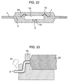
- Fig. 22 shows a state in which the outer plating is applied to the outer lead 5 after molding the resin, and the outer plating is completed.
- the metal used for the outer plating in the present embodiment is an alloy obtained by adding Cu and/or Bi to the Sn-Ag system metal. This is because Pb reduction is realized and a reflow mounting having a high reflow temperature is supposed. Accordingly, it is a matter of course that it is possible to employ an alloy among Zn, In, Sb and Sn or an Sn system alloy in addition to the alloy mentioned above.
- a bonding cream solder includes a structure having a different mounting temperature such as an Sn-Ag system, an Sn-Zn system, an Sn-Bi system and the like.
- the Sn-Ag system metal has a melting point higher than a melting point of the Pb containing solder.
- the outer plating uses a lead system solder. This is because in the case of paying attention to the fact that the bonding strength between the inner lead 4 and the wire 19 is increased by applying the palladium plating to the inner lead 4, it is not necessary to limit the outer plating to the lead system solder.
- the resin molding body is held and fixed at a root portion of the outer lead 5 and the outer lead 5 is formed by a punch 25.
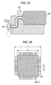
- the front end portion of the outer lead 5 is cut and formed by moving a die 26 from a lower portion as shown in Fig. 24.
- Fig. 25 is a schematic view of a completed product in the present embodiment
- Fig. 27 is a perspective view of the schematic view
- Fig. 26 is a cross sectional view along a line E-F in Fig. 27.
- the number of pins is 208, however, the reduced number of pins are illustrated in the drawings in order to avoid troublesome.
- the shape of the resin molding body is obtained by beveling one corner and cutting a sign so as to secure a directivity of the package at a time of handling for mounting.
- a size D of the resin molding body is 28 mm square
- an outer size of the semiconductor package including the outer lead 5 is 30.6 ⁇ 0.2 mm
- a height is 3.56 mm at the maximum.
- a pitch p of the lead is 0.5 mm
- a width w of each of the leads is 0.2 mm
- a thickness t is 0.15 mm.
- a length a in a horizontal direction between the resin molding body and the front end of the outer lead is 1.3 mm
- a length k of the front end of the bent outer lead is 0.5 mm.
- a solder paste 28 is applied onto a foot print 29 greater than the mounting surface in the front end of the outer lead 5.
- the mounting operation is performed by arranging a package 31 from the above after application and applying a heat.
- the reflowing methods include a vapor phase reflow, an air reflow, an infrared rays reflow and the like.
- the reflow temperature is 255°C , and is 20°C higher than the reflow temperature 235°C of the normal Sn-Pb system solder. This is because it is possible to correspond to the fact that the melting point of the solder is high.
- a width a is 0.20 to 0.25 mm and a length b is 1.3 mm.
- the present invention is employed for the purpose of manufacturing QFP, however, the present invention can be applied to a surface mounting type package such as QFN, QFJ or the like without being limited to QFP, and further the present invention can be applied to general packages having wire connecting portions such as a small outline non-leaded package in which a pad arranged in the middle of a chip is connected to a lead by a wire.
- the structure is made such as to improve a connecting strength of the portion in which the wire corresponding to the connecting member is adhered and connected to the inner lead corresponding to the member to be connected, however, the connecting member is not limited to the wire, and the member to be connected is not limited to the lead.
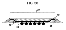
- the present invention can be applied to the case of applying the Pd plating to a pad 40 corresponding to a portion for adhering and connecting a lead corresponding to a connecting member 42 to a semiconductor chip 39 in a chip size package or the like which employs an insulative member such as a polyimide tape 43 or the like for a base material and is mounted on a substrate by a solder ball as shown in a schematic cross sectional view in Fig. 30. That is, the present invention can be generally applied to improvement of connecting property and reliability in the connecting portion, in the semiconductor device.
- an LSI package corresponding to the lead-free in particular, an LSI package using the lead-free alternate solder having a melting point higher than that of the Pb system solder, and it is possible to improve an assembling yield and a reliability. Further, it is possible to provide an LSI package corresponding to the narrow wire caused by the increase of pins in the package or the increase of size thereof and the chip shrink, and it is possible to improve an assembling yield and a reliability.
Landscapes
- Lead Frames For Integrated Circuits (AREA)
- Wire Bonding (AREA)
- Die Bonding (AREA)
Priority Applications (1)
| Application Number | Priority Date | Filing Date | Title |
|---|---|---|---|
| EP08006981A EP2028684A3 (de) | 2000-02-18 | 2001-02-05 | Integrierte Halbleiterschaltungsvorrichtung und Herstellungsverfahren dafür |
Applications Claiming Priority (2)
| Application Number | Priority Date | Filing Date | Title |
|---|---|---|---|
| JP2000046724A JP2001230360A (ja) | 2000-02-18 | 2000-02-18 | 半導体集積回路装置およびその製造方法 |
| JP2000046724 | 2000-02-18 |
Related Child Applications (1)
| Application Number | Title | Priority Date | Filing Date |
|---|---|---|---|
| EP08006981A Division EP2028684A3 (de) | 2000-02-18 | 2001-02-05 | Integrierte Halbleiterschaltungsvorrichtung und Herstellungsverfahren dafür |
Publications (2)
| Publication Number | Publication Date |
|---|---|
| EP1126520A2 true EP1126520A2 (de) | 2001-08-22 |
| EP1126520A3 EP1126520A3 (de) | 2002-11-20 |
Family
ID=18569088
Family Applications (2)
| Application Number | Title | Priority Date | Filing Date |
|---|---|---|---|
| EP08006981A Withdrawn EP2028684A3 (de) | 2000-02-18 | 2001-02-05 | Integrierte Halbleiterschaltungsvorrichtung und Herstellungsverfahren dafür |
| EP01102524A Withdrawn EP1126520A3 (de) | 2000-02-18 | 2001-02-05 | IC-Vorrichtung und Methode zur Herstellung |
Family Applications Before (1)
| Application Number | Title | Priority Date | Filing Date |
|---|---|---|---|
| EP08006981A Withdrawn EP2028684A3 (de) | 2000-02-18 | 2001-02-05 | Integrierte Halbleiterschaltungsvorrichtung und Herstellungsverfahren dafür |
Country Status (8)
| Country | Link |
|---|---|
| US (6) | US6891253B2 (de) |
| EP (2) | EP2028684A3 (de) |
| JP (1) | JP2001230360A (de) |
| KR (2) | KR100780207B1 (de) |
| CN (5) | CN100380650C (de) |
| MY (1) | MY124877A (de) |
| SG (1) | SG96200A1 (de) |
| TW (1) | TW504827B (de) |
Families Citing this family (32)
| Publication number | Priority date | Publication date | Assignee | Title |
|---|---|---|---|---|
| US6357112B1 (en) * | 1997-11-25 | 2002-03-19 | Tessera, Inc. | Method of making connection component |
| JP2001230360A (ja) * | 2000-02-18 | 2001-08-24 | Hitachi Ltd | 半導体集積回路装置およびその製造方法 |
| JP4549491B2 (ja) * | 2000-03-13 | 2010-09-22 | 大日本印刷株式会社 | 樹脂封止型半導体装置 |
| JP2002299540A (ja) | 2001-04-04 | 2002-10-11 | Hitachi Ltd | 半導体装置およびその製造方法 |
| TWI267959B (en) * | 2002-11-27 | 2006-12-01 | Siliconware Precision Industries Co Ltd | Semiconductor package with chip-supporting member |
| JP4417150B2 (ja) * | 2004-03-23 | 2010-02-17 | 株式会社ルネサステクノロジ | 半導体装置 |
| KR20070015164A (ko) * | 2004-05-25 | 2007-02-01 | 신꼬오덴기 고교 가부시키가이샤 | 반도체 부품의 외장 팔라듐 도금 구조 및 반도체 장치의제조 방법 |
| US7215014B2 (en) * | 2004-07-29 | 2007-05-08 | Freescale Semiconductor, Inc. | Solderable metal finish for integrated circuit package leads and method for forming |
| US7268415B2 (en) * | 2004-11-09 | 2007-09-11 | Texas Instruments Incorporated | Semiconductor device having post-mold nickel/palladium/gold plated leads |
| US7615851B2 (en) * | 2005-04-23 | 2009-11-10 | Stats Chippac Ltd. | Integrated circuit package system |
| JP2007081235A (ja) * | 2005-09-15 | 2007-03-29 | Renesas Technology Corp | 半導体装置の製造方法 |
| JP4820616B2 (ja) | 2005-10-20 | 2011-11-24 | パナソニック株式会社 | リードフレーム |
| DE102006015222B4 (de) * | 2006-03-30 | 2018-01-04 | Robert Bosch Gmbh | QFN-Gehäuse mit optimierter Anschlussflächengeometrie |
| US20080001264A1 (en) * | 2006-07-03 | 2008-01-03 | Texas Instruments Incorporated | Exposed top side copper leadframe manufacturing |
| JP2008098478A (ja) * | 2006-10-13 | 2008-04-24 | Renesas Technology Corp | 半導体装置及びその製造方法 |
| JP5341679B2 (ja) * | 2009-08-31 | 2013-11-13 | 株式会社日立製作所 | 半導体装置 |
| CN102484083A (zh) | 2009-09-11 | 2012-05-30 | 罗姆股份有限公司 | 半导体装置及其制造方法 |
| JP2011216518A (ja) * | 2010-03-31 | 2011-10-27 | Rohm Co Ltd | ワイヤボンディング構造、半導体装置、ボンディングツールおよびワイヤボンディング方法 |
| JP5634149B2 (ja) | 2010-07-16 | 2014-12-03 | ルネサスエレクトロニクス株式会社 | 半導体装置 |
| TWI436710B (zh) * | 2011-02-09 | 2014-05-01 | 村田製作所股份有限公司 | Connection structure |
| CN102354688A (zh) * | 2011-10-11 | 2012-02-15 | 深圳市威怡电气有限公司 | 一种功率模块 |
| CN102779763A (zh) * | 2012-06-05 | 2012-11-14 | 华天科技(西安)有限公司 | 一种基于腐蚀的aaqfn产品的二次塑封制作工艺 |
| JP6121692B2 (ja) * | 2012-11-05 | 2017-04-26 | ルネサスエレクトロニクス株式会社 | 半導体装置およびその製造方法 |
| JP6238121B2 (ja) * | 2013-10-01 | 2017-11-29 | ローム株式会社 | 半導体装置 |
| JP6414669B2 (ja) * | 2014-07-22 | 2018-10-31 | 大口マテリアル株式会社 | リードフレーム及びその製造方法 |
| US9070392B1 (en) | 2014-12-16 | 2015-06-30 | Hutchinson Technology Incorporated | Piezoelectric disk drive suspension motors having plated stiffeners |
| CN107735834B (zh) | 2015-06-30 | 2019-11-19 | 哈钦森技术股份有限公司 | 具有改进的可靠性的盘驱动器头部悬架结构 |
| CN110544633A (zh) * | 2018-05-28 | 2019-12-06 | 浙江清华柔性电子技术研究院 | 芯片集成方法及芯片集成结构 |
| US10658278B2 (en) * | 2018-08-16 | 2020-05-19 | Texas Instruments Incorporated | Electrical device terminal finishing |
| JP7293142B2 (ja) * | 2020-01-07 | 2023-06-19 | 東芝デバイス&ストレージ株式会社 | 半導体装置 |
| KR102405129B1 (ko) * | 2021-05-21 | 2022-06-07 | 제엠제코(주) | 히트싱크 노출형 반도체 패키지 및 이의 제조방법 |
| CN118431186A (zh) * | 2024-07-04 | 2024-08-02 | 长沙瑶华半导体科技有限公司 | 半导体结构、电路及其封装方法 |
Citations (1)
| Publication number | Priority date | Publication date | Assignee | Title |
|---|---|---|---|---|
| US5889317A (en) * | 1997-04-09 | 1999-03-30 | Sitron Precision Co., Ltd. | Leadframe for integrated circuit package |
Family Cites Families (55)
| Publication number | Priority date | Publication date | Assignee | Title |
|---|---|---|---|---|
| JPS5282183A (en) * | 1975-12-29 | 1977-07-09 | Nec Corp | Connecting wires for semiconductor devices |
| JPS61140160A (ja) * | 1984-12-12 | 1986-06-27 | Hitachi Cable Ltd | 半導体用リ−ドフレ−ム |
| JPH05144821A (ja) * | 1991-04-30 | 1993-06-11 | Toshiba Corp | 半導体装置 |
| JP3044872B2 (ja) | 1991-09-25 | 2000-05-22 | ソニー株式会社 | 半導体装置 |
| JPH0590465A (ja) * | 1991-09-27 | 1993-04-09 | Mitsui High Tec Inc | 半導体装置 |
| JPH05211261A (ja) * | 1991-10-14 | 1993-08-20 | Fujitsu Ltd | 半導体装置 |
| EP0537982A2 (de) * | 1991-10-14 | 1993-04-21 | Fujitsu Limited | Halbleiteranordnung mit verbesserten Leitern |
| KR100552353B1 (ko) * | 1992-03-27 | 2006-06-20 | 가부시키가이샤 히타치초엘에스아이시스템즈 | 리이드프레임및그것을사용한반도체집적회로장치와그제조방법 |
| US5650661A (en) * | 1993-12-27 | 1997-07-22 | National Semiconductor Corporation | Protective coating combination for lead frames |
| US5455195A (en) * | 1994-05-06 | 1995-10-03 | Texas Instruments Incorporated | Method for obtaining metallurgical stability in integrated circuit conductive bonds |
| US5454929A (en) * | 1994-06-16 | 1995-10-03 | National Semiconductor Corporation | Process for preparing solderable integrated circuit lead frames by plating with tin and palladium |
| JP3509274B2 (ja) * | 1994-07-13 | 2004-03-22 | セイコーエプソン株式会社 | 樹脂封止型半導体装置およびその製造方法 |
| US5891745A (en) * | 1994-10-28 | 1999-04-06 | Honeywell Inc. | Test and tear-away bond pad design |
| KR0163863B1 (ko) * | 1995-02-28 | 1998-12-01 | 김광호 | 멀티칩 실장을 위한 반도체 패키지 |
| JP3501316B2 (ja) | 1995-06-16 | 2004-03-02 | 株式会社ルネサステクノロジ | 半導体装置及びその製造方法 |
| US5818699A (en) * | 1995-07-05 | 1998-10-06 | Kabushiki Kaisha Toshiba | Multi-chip module and production method thereof |
| KR100266726B1 (ko) * | 1995-09-29 | 2000-09-15 | 기타지마 요시토시 | 리드프레임과 이 리드프레임을 갖춘 반도체장치 |
| JPH09232493A (ja) * | 1995-12-20 | 1997-09-05 | Seiichi Serizawa | リードフレーム |
| US5902472A (en) * | 1996-01-30 | 1999-05-11 | Naganoken And Shinko Electric Industries Co., Ltd. | Aqueous solution for forming metal complexes, tin-silver alloy plating bath, and process for producing plated object using the plating bath |
| JPH09312375A (ja) * | 1996-03-18 | 1997-12-02 | Hitachi Ltd | リードフレーム、半導体装置及び半導体装置の製造方法 |
| JPH09312374A (ja) | 1996-05-24 | 1997-12-02 | Sony Corp | 半導体パッケージ及びその製造方法 |
| DE19626087C2 (de) | 1996-06-28 | 1998-06-10 | Siemens Ag | Integrierte Halbleiterschaltung mit Leiterrahmen und Gehäuse |
| JPH1018056A (ja) * | 1996-07-02 | 1998-01-20 | Daido Steel Co Ltd | リードフレーム用板とその製造方法 |
| CN1132244C (zh) * | 1996-07-03 | 2003-12-24 | 精工爱普生株式会社 | 树脂封装型半导体装置及其制造方法 |
| US5926694A (en) | 1996-07-11 | 1999-07-20 | Pfu Limited | Semiconductor device and a manufacturing method thereof |
| US5929511A (en) * | 1996-07-15 | 1999-07-27 | Matsushita Electronics Corporation | Lead frame for resin sealed semiconductor device |
| TW335526B (en) * | 1996-07-15 | 1998-07-01 | Matsushita Electron Co Ltd | A semiconductor and the manufacturing method |
| JP3160555B2 (ja) * | 1996-07-15 | 2001-04-25 | 松下電子工業株式会社 | 半導体装置およびその製造方法 |
| JPH1070230A (ja) * | 1996-08-27 | 1998-03-10 | Hitachi Cable Ltd | Loc用リードフレーム |
| JPH10233408A (ja) * | 1997-02-21 | 1998-09-02 | Nec Corp | 金属接合構造及び半導体装置 |
| US6037653A (en) * | 1997-03-25 | 2000-03-14 | Samsung Aerospace Industries, Ltd. | Semiconductor lead frame having multi-layered plating layer including copper-nickel plating layer |
| JPH10284666A (ja) * | 1997-04-01 | 1998-10-23 | Furukawa Electric Co Ltd:The | 電子部品機器 |
| US5994767A (en) * | 1997-04-09 | 1999-11-30 | Sitron Precision Co., Ltd. | Leadframe for integrated circuit package and method of manufacturing the same |
| KR100215120B1 (ko) * | 1997-04-21 | 1999-08-16 | 유무성 | 리이드 프레임 도금 장치 및 그에 의한 리이드 프레임 도금 방법 |
| JP3003624B2 (ja) * | 1997-05-27 | 2000-01-31 | ソニー株式会社 | 半導体装置 |
| JPH118341A (ja) * | 1997-06-18 | 1999-01-12 | Mitsui High Tec Inc | 半導体装置用リードフレーム |
| JPH1167809A (ja) | 1997-08-26 | 1999-03-09 | Sanyo Electric Co Ltd | 半導体装置 |
| JPH11145369A (ja) * | 1997-11-07 | 1999-05-28 | Hitachi Ltd | リードフレームおよびそれを用いた半導体装置ならびにその製造方法 |
| JPH11168169A (ja) * | 1997-12-04 | 1999-06-22 | Hitachi Ltd | リードフレームおよびそれを用いた半導体装置ならびにその製造方法 |
| JP3622462B2 (ja) * | 1997-12-16 | 2005-02-23 | 株式会社日立製作所 | 半導体装置 |
| JP3481448B2 (ja) * | 1998-01-30 | 2003-12-22 | 古河電気工業株式会社 | リードフレーム |
| US6292083B1 (en) * | 1998-03-27 | 2001-09-18 | Taiyo Yuden Co., Ltd. | Surface-mount coil |
| US6087714A (en) * | 1998-04-27 | 2000-07-11 | Matsushita Electric Industrial Co., Ltd. | Semiconductor devices having tin-based solder film containing no lead and process for producing the devices |
| JPH11307710A (ja) * | 1998-04-27 | 1999-11-05 | Matsushita Electric Ind Co Ltd | メッキリードフレーム及びその製造方法及びそれを用いた半導体装置 |
| JPH11330134A (ja) * | 1998-05-12 | 1999-11-30 | Hitachi Ltd | ワイヤボンディング方法およびその装置並びに半導体装置 |
| US6139977A (en) * | 1998-06-10 | 2000-10-31 | Lucent Technologies Inc. | Palladium surface coating suitable for wirebonding and process for forming palladium surface coatings |
| US6194777B1 (en) * | 1998-06-27 | 2001-02-27 | Texas Instruments Incorporated | Leadframes with selective palladium plating |
| CN1190840C (zh) * | 1999-04-08 | 2005-02-23 | 新光电气工业株式会社 | 半导体装置用引线框架 |
| JP3314754B2 (ja) | 1999-04-22 | 2002-08-12 | 松下電器産業株式会社 | 鉛を含まない錫ベース半田皮膜を有する半導体装置およびその製造方法 |
| US6376901B1 (en) * | 1999-06-08 | 2002-04-23 | Texas Instruments Incorporated | Palladium-spot leadframes for solder plated semiconductor devices and method of fabrication |
| JP2001230360A (ja) * | 2000-02-18 | 2001-08-24 | Hitachi Ltd | 半導体集積回路装置およびその製造方法 |
| JP3664045B2 (ja) * | 2000-06-01 | 2005-06-22 | セイコーエプソン株式会社 | 半導体装置の製造方法 |
| JP3417395B2 (ja) * | 2000-09-21 | 2003-06-16 | 松下電器産業株式会社 | 半導体装置用リードフレーム及びその製造方法及びそれを用いた半導体装置 |
| US6818968B1 (en) * | 2000-10-12 | 2004-11-16 | Altera Corporation | Integrated circuit package and process for forming the same |
| US6452258B1 (en) * | 2000-11-06 | 2002-09-17 | Lucent Technologies Inc. | Ultra-thin composite surface finish for electronic packaging |
-
2000
- 2000-02-18 JP JP2000046724A patent/JP2001230360A/ja active Pending
-
2001
- 2001-02-05 EP EP08006981A patent/EP2028684A3/de not_active Withdrawn
- 2001-02-05 EP EP01102524A patent/EP1126520A3/de not_active Withdrawn
- 2001-02-08 TW TW090102796A patent/TW504827B/zh not_active IP Right Cessation
- 2001-02-16 SG SG200100859A patent/SG96200A1/en unknown
- 2001-02-16 CN CNB011046228A patent/CN100380650C/zh not_active Expired - Fee Related
- 2001-02-16 CN CNB2006101030461A patent/CN100440493C/zh not_active Expired - Fee Related
- 2001-02-16 CN CNB031004415A patent/CN1312748C/zh not_active Expired - Fee Related
- 2001-02-16 CN CNA2006101030480A patent/CN101013683A/zh active Pending
- 2001-02-16 CN CNA2006101030476A patent/CN101013682A/zh active Pending
- 2001-02-16 MY MYPI20010716A patent/MY124877A/en unknown
- 2001-02-17 KR KR1020010008002A patent/KR100780207B1/ko not_active Expired - Fee Related
- 2001-02-20 US US09/785,452 patent/US6891253B2/en not_active Expired - Fee Related
- 2001-05-09 US US09/851,108 patent/US20010018264A1/en not_active Abandoned
-
2002
- 2002-11-18 US US10/295,908 patent/US7176056B2/en not_active Expired - Fee Related
-
2004
- 2004-07-14 US US10/890,321 patent/US7038306B2/en not_active Expired - Fee Related
-
2006
- 2006-02-28 US US11/362,732 patent/US7397114B2/en not_active Expired - Fee Related
-
2007
- 2007-06-21 KR KR1020070061216A patent/KR100750012B1/ko not_active Expired - Fee Related
-
2008
- 2008-06-04 US US12/133,210 patent/US20090014855A1/en not_active Abandoned
Patent Citations (1)
| Publication number | Priority date | Publication date | Assignee | Title |
|---|---|---|---|---|
| US5889317A (en) * | 1997-04-09 | 1999-03-30 | Sitron Precision Co., Ltd. | Leadframe for integrated circuit package |
Also Published As
| Publication number | Publication date |
|---|---|
| TW504827B (en) | 2002-10-01 |
| CN1309425A (zh) | 2001-08-22 |
| US7397114B2 (en) | 2008-07-08 |
| US20060138617A1 (en) | 2006-06-29 |
| MY124877A (en) | 2006-07-31 |
| KR100750012B1 (ko) | 2007-08-16 |
| EP2028684A3 (de) | 2009-06-03 |
| KR20010082736A (ko) | 2001-08-30 |
| EP2028684A2 (de) | 2009-02-25 |
| CN101013683A (zh) | 2007-08-08 |
| US20010015481A1 (en) | 2001-08-23 |
| KR20070070146A (ko) | 2007-07-03 |
| CN101013682A (zh) | 2007-08-08 |
| CN100380650C (zh) | 2008-04-09 |
| US20030067067A1 (en) | 2003-04-10 |
| US20090014855A1 (en) | 2009-01-15 |
| US7038306B2 (en) | 2006-05-02 |
| US7176056B2 (en) | 2007-02-13 |
| CN1312748C (zh) | 2007-04-25 |
| CN1516252A (zh) | 2004-07-28 |
| CN100440493C (zh) | 2008-12-03 |
| EP1126520A3 (de) | 2002-11-20 |
| US20040245607A1 (en) | 2004-12-09 |
| CN101026139A (zh) | 2007-08-29 |
| US6891253B2 (en) | 2005-05-10 |
| SG96200A1 (en) | 2003-05-23 |
| US20010018264A1 (en) | 2001-08-30 |
| JP2001230360A (ja) | 2001-08-24 |
| KR100780207B1 (ko) | 2007-11-27 |
Similar Documents
| Publication | Publication Date | Title |
|---|---|---|
| US6891253B2 (en) | Semiconductor integrated circuit device and method of manufacturing the same | |
| US7368328B2 (en) | Semiconductor device having post-mold nickel/palladium/gold plated leads | |
| US6550666B2 (en) | Method for forming a flip chip on leadframe semiconductor package | |
| US6828660B2 (en) | Semiconductor device with double nickel-plated leadframe | |
| US20060049517A1 (en) | Flip chip semiconductor device and manufacturing method thereof | |
| US6583500B1 (en) | Thin tin preplated semiconductor leadframes | |
| US6376901B1 (en) | Palladium-spot leadframes for solder plated semiconductor devices and method of fabrication | |
| US20210265214A1 (en) | Methods and apparatus for an improved integrated circuit package | |
| EP1037277A2 (de) | Leiterrahmen | |
| US20040183166A1 (en) | Preplated leadframe without precious metal | |
| US6019274A (en) | Semiconductor device and mounting method therefor | |
| EP0154187A2 (de) | Bandmontagematerial und Struktur zum Herstellen einer elektronischen Schaltung | |
| JP3540249B2 (ja) | 半導体デバイスパッケージの外部リードを外部電極に接続する方法 | |
| JP2006352175A (ja) | 半導体集積回路装置 | |
| CN116686080A (zh) | 可配置的有引线的封装件 |
Legal Events
| Date | Code | Title | Description |
|---|---|---|---|
| PUAI | Public reference made under article 153(3) epc to a published international application that has entered the european phase |
Free format text: ORIGINAL CODE: 0009012 |
|
| AK | Designated contracting states |
Kind code of ref document: A2 Designated state(s): AT BE CH CY DE DK ES FI FR GB GR IE IT LI LU MC NL PT SE TR |
|
| AX | Request for extension of the european patent |
Free format text: AL;LT;LV;MK;RO;SI |
|
| PUAL | Search report despatched |
Free format text: ORIGINAL CODE: 0009013 |
|
| AK | Designated contracting states |
Kind code of ref document: A3 Designated state(s): AT BE CH CY DE DK ES FI FR GB GR IE IT LI LU MC NL PT SE TR |
|
| AX | Request for extension of the european patent |
Free format text: AL;LT;LV;MK;RO;SI |
|
| RIC1 | Information provided on ipc code assigned before grant |
Free format text: 7H 01L 23/495 A, 7H 01L 23/49 B, 7H 01L 21/607 B |
|
| 17P | Request for examination filed |
Effective date: 20030513 |
|
| AKX | Designation fees paid |
Designated state(s): DE FR GB IT |
|
| 17Q | First examination report despatched |
Effective date: 20071123 |
|
| RAP1 | Party data changed (applicant data changed or rights of an application transferred) |
Owner name: RENESAS TECHNOLOGY CORP. |
|
| RAP1 | Party data changed (applicant data changed or rights of an application transferred) |
Owner name: RENESAS ELECTRONICS CORPORATION |
|
| STAA | Information on the status of an ep patent application or granted ep patent |
Free format text: STATUS: THE APPLICATION IS DEEMED TO BE WITHDRAWN |
|
| 18D | Application deemed to be withdrawn |
Effective date: 20120207 |