EP1148522A2 - Réactance à faible perte et à faible bruit - Google Patents
Réactance à faible perte et à faible bruit Download PDFInfo
- Publication number
- EP1148522A2 EP1148522A2 EP01109357A EP01109357A EP1148522A2 EP 1148522 A2 EP1148522 A2 EP 1148522A2 EP 01109357 A EP01109357 A EP 01109357A EP 01109357 A EP01109357 A EP 01109357A EP 1148522 A2 EP1148522 A2 EP 1148522A2
- Authority
- EP
- European Patent Office
- Prior art keywords
- wound
- shape
- coil
- iron core
- elliptical
- Prior art date
- Legal status (The legal status is an assumption and is not a legal conclusion. Google has not performed a legal analysis and makes no representation as to the accuracy of the status listed.)
- Granted
Links
Images


Classifications
-
- H—ELECTRICITY
- H01—ELECTRIC ELEMENTS
- H01F—MAGNETS; INDUCTANCES; TRANSFORMERS; SELECTION OF MATERIALS FOR THEIR MAGNETIC PROPERTIES
- H01F27/00—Details of transformers or inductances, in general
- H01F27/06—Mounting, supporting or suspending transformers, reactors or choke coils not being of the signal type
-
- H—ELECTRICITY
- H01—ELECTRIC ELEMENTS
- H01F—MAGNETS; INDUCTANCES; TRANSFORMERS; SELECTION OF MATERIALS FOR THEIR MAGNETIC PROPERTIES
- H01F17/00—Fixed inductances of the signal type
- H01F17/04—Fixed inductances of the signal type with magnetic core
- H01F17/06—Fixed inductances of the signal type with magnetic core with core substantially closed in itself, e.g. toroid
- H01F17/062—Toroidal core with turns of coil around it
-
- H—ELECTRICITY
- H01—ELECTRIC ELEMENTS
- H01F—MAGNETS; INDUCTANCES; TRANSFORMERS; SELECTION OF MATERIALS FOR THEIR MAGNETIC PROPERTIES
- H01F27/00—Details of transformers or inductances, in general
- H01F27/24—Magnetic cores
- H01F27/25—Magnetic cores made from strips or ribbons
-
- Y—GENERAL TAGGING OF NEW TECHNOLOGICAL DEVELOPMENTS; GENERAL TAGGING OF CROSS-SECTIONAL TECHNOLOGIES SPANNING OVER SEVERAL SECTIONS OF THE IPC; TECHNICAL SUBJECTS COVERED BY FORMER USPC CROSS-REFERENCE ART COLLECTIONS [XRACs] AND DIGESTS
- Y10—TECHNICAL SUBJECTS COVERED BY FORMER USPC
- Y10T—TECHNICAL SUBJECTS COVERED BY FORMER US CLASSIFICATION
- Y10T29/00—Metal working
- Y10T29/49—Method of mechanical manufacture
- Y10T29/49002—Electrical device making
- Y10T29/4902—Electromagnet, transformer or inductor
- Y10T29/49071—Electromagnet, transformer or inductor by winding or coiling
Definitions
- the present invention relates to a reactor that is used as an inductance element of an inverter circuit, a converter circuit, and the like.
- Use of a laminated iron core in the magnetic core of a reactor used in a high frequency wave band in an inverter circuit, a converter circuit, and the like can reduce the size of the reactor owing to a high magnetic flux density as compared with the use of other material magnetic cores.
- the laminating material uses a soft magnetic sheet such as silicon steel sheet having a small thickness and a large specific resistance.
- Fig. 1A plane view
- Coils 2a and 2b are wound around a laminated iron core 11 that comprises iron cores 11a and 11b which have a square cross section and which are laminated with soft magnetic sheets 110.
- each of the coils 2a and 2b comprises a rectangular conductor wire 20 wound in an upright orientation. Since the rectangular conductor wire 20 has high rigidity, it cannot be wound in a square pattern along the surface of the laminated iron core 11. Thus, the rectangular conductor wire 20 is wound in a circular pattern as shown in Fig. 1B (which is a sectional view along line I-I in Fig. 1A).
- An object of the present invention is to provide a reactor which generates low noise and low loss without inducing the above-described problems.
- a low noise and low loss reactor which comprises a wound and laminated iron core formed by winding a soft magnetic thin strip into a circular ring shape or elliptical ring shape, and a coil wound around almost an entire outer periphery of the ring of wound and laminated iron core, wherein a cross sectional shape of the wound and laminated iron core vertical to a peripheral direction of the ring is any one of: (i) a circular shape, (ii) an elliptical shape, (iii) a substantially regular polygon of at least 6 sides, (iv) a shape encircled by a pair of point-symmetrically positioned circular arcs or elliptical arcs with a nearly straight line connecting respective edges of the pair of circular arcs or elliptical arcs on both sides of the pair of circular arcs or elliptical arcs, and (v) a shape of a substantially regular polygon of at least 4 sides whose apexes comprise
- the inventors of the present invention studied reactors which generate less noise and less loss, and which actualize easier fabrication than conventional reactors used in a high frequency wave band, focusing on the structure and material of the laminated iron core and coil components.
- a cross sectional shape of the wound and laminated iron core vertical to a peripheral direction of the ring is any one of: (i) a circular shape, (ii) an elliptical shape, (iii) a substantially regular polygon of at least 6 sides, (iv) a shape encircled by a pair of point-symmetrically positioned circular arcs or elliptical arcs with a nearly straight line connecting respective edges of the pair of circular arcs or elliptical arcs on both sides of the pair of circular arcs or elliptical arcs, and (v) a shape of a substantially regular polygon of at least
- the space factor increases by a maximum of approximately 57% and the magnetic flux density decreases by about 36% as compared with conventional reactors, thus effectively reducing the iron loss.
- the vibration noise caused from space is effectively suppressed.
- cross sectional shape of this type of wound and laminated iron core does not necessarily have to be exactly one of the above-described shapes, and the effect of the present invention can be attained even if the shape is only close to one of the above-described shapes.
- the thickness of an insulating film is kept to be very thin to prevent reduction in space factor.
- the thin insulating film is, however, likely to be damaged by a cut burr generated on edge portions of stacked soft magnetic thin strip, thus likely a generating micro-short circuit.
- the straight line section or a majority portion thereof forming the outer periphery of the cross section vertical to the peripheral direction of the ring of wound and laminated iron core is not in parallel with a centerline drawn passing through the center in the width direction of the laminated soft magnetic thin strip along the laminating direction.
- Fig. 2A (which is a plan view), Fig. 2B (which is a sectional view along line II-II of Fig. 2A), and Fig. 3 show an example of a reactor according to the present invention.
- the reactor comprises a wound and laminated iron core 1 formed by winding a soft magnetic thin strip shown in Fig. 4A in a circular ring shape along the centerline in a width direction thereof, and a rectangular conductor wire coil 2 wound in an upright orientation over almost the entire periphery of the wound and laminated iron core 1, wherein the cross sectional shape of the wound and laminated iron core 1 vertical to the periphery of the ring is in a circular shape.
- Fig. 3 shows the plan view of the wound and laminated iron core 1 of Fig. 2 viewed from above the periphery of the circular ring.
- the rectangular conductor wire coil 2 wound in the upright orientation is formed by winding a rectangular conductor wire 20 in an upright orientation over almost the entire periphery of the wound and laminated iron core 1 in a circular ring shape
- the rectangular conductor wire 20 spreads in radial directions (i.e., in a fan shape) from the inner peripheral side of the wound and laminated iron core to the outer peripheral side thereof, as shown in Fig. 2A.
- the range of winding of the rectangular conductor wire coil 2 in the upright orientation in the peripheral direction of the wound and laminated iron core 1 may be almost the entire periphery of the wound and laminated iron core 1.
- a non-wound section may be provided, as seen in Fig. 2A.
- this type of reactor can reduce the switching noise caused from the leakage of current via a parasitic capacitor to one tenth or less as compared with conventional type reactors because of the state of non-touching between adjacent portions of the rectangular conductor wire 20 and because of less series capacitance therebetween.
- the noise abatement parts which are externally mounted to prevent switching noise can be significantly simplified.
- the capacitance C of a capacitor shown in Fig. 5A is determined by the electrode area S, the distance between electrodes d, and the dielectric constant ⁇ of the insulation material, and is expressed by the following equation.
- C ⁇ S/d
- the capacitance C of the capacitor is proportional to the dielectric constant ⁇ of the insulation material, and inversely proportional to the distance d between electrodes, (or the thickness of the insulation material).
- the capacitance C of a parasitic capacitor between adjacent rectangular conductor wires in a reactor shown in Fig. 5B the side face area of the rectangular conductor wire corresponds to the electrode area S, and the distance between adjacent rectangular conductor wires corresponds to the distance d between electrodes.
- the capacitance C of the parasitic capacitor between adjacent rectangular conductor wires is determined by these variables and the dielectric constant ⁇ using the equation given above.
- a conventional type reactor gives close contact between adjacent portions of the rectangular conductor wire 20 via an insulating film having about 0.1 mm in thickness on respective surfaces of the rectangular conductor wire.
- the reactor according to the present invention which is shown in Fig. 6B, since the rectangular conductor wire 20 spreads in radial direction from the inner peripheral side of the wound and laminated iron core to the outer peripheral side thereof, there exists an air layer or a resin layer for coil adhesion, as well as the insulating film having about 0.2 mm in thickness, between adjacent portions of the rectangular conductor wire 20.
- the dielectric constant ⁇ decreases, and the distance d between electrodes increases (to about eleven times or more than that in the conventional type), thus significantly reducing the capacitance of the parasitic capacitor between adjacent portions of the rectangular conductor wire 20 (to about one tenth).
- the switching noise caused from the leakage of current via the parasitic capacitor becomes about one tenth.
- the coils are located in a parallel proximity arrangement to minimize the reactor size, which induces increased parallel capacitance between coils.
- the arrangement induces the generation of resonance current within the coil when the rectangular wave current is OFF, which worsens the switching noise characteristic.
- the reactor according to the present invention achieves a significantly large inner diameter of the coil ring as compared with the coil distance in the conventional type reactor.
- the parallel capacitance between coils facing to each other in the radius direction of the reactor is very small (about one tenth) as compared with the conventional type reactor. Therefore, the generation of resonance current within the coil becomes difficult when rectangular wave current is OFF.
- the EMI characteristic is significantly improved.
- the reactor according to the present invention achieves a small alternating effective resistance owing to the proximity effect, so that the coil calorific loss of the reactor becomes significantly smaller than that in the conventional type reactor.
- the reason for this phenomenon is the following.
- Resistance of a conductor wire is determined by the dielectric current resistance + skin effect + proximity effect.
- high frequency wave current tends to flow through skin portion of the conductor, and avoids flowing through the center portion thereof. Accordingly, it is difficult for a high frequency wave current to flow through the conductor wire.
- the frequency is extremely increased, current flows through only the skin portion, and the cross sectional area of the conductor available for the flow of high frequency wave current is limited only to the skin portion.
- the alternating effective resistance becomes large as compared with the direct current resistance (skin effect).
- the skin area is necessarily increased. To do this, a rectangular conductor wire wound in an upright orientation or a litz wire is more preferable than a round conductor wire.
- the reactor according to the present invention provides a radially spreading coil winding pattern from the inner peripheral side of the wound and laminated iron core to the outer peripheral side thereof.
- the alternating effective resistance caused by the proximity effect can be reduced, and the coil calorific loss is reduced by 25 to 51% as compared with that of the conventional type reactor.
- the reactor according to the present invention produced an effective resistance of 0.156 ⁇ /20 kHz and 0.330 ⁇ /100 kHz, respectively, while the conventional type reactor gave 0.206 ⁇ /20 kHz and 0.670 ⁇ /20 kHz, respectively. That is, the reactor according to the present invention reduced the effective resistance by 24% and 51% for the respective frequencies.
- the conventional type reactor comprises closely contacted adjacent portions of the rectangular conductor wire 20, as shown in Fig. 6A, the contact area between the coil and air is limited to the side faces of the rectangular conductor wire 20. Furthermore, since the coils are located in a parallel proximity arrangement, effective heat dissipation cannot be attained. To the contrary, with the reactor according to the present invention, adjacent portions of the rectangular conductor wire 20 are not in contact to each other, as shown in Fig. 6B, and the inner diameter of the coil ring is larger than the distance between coils of the conventional type reactor. Thus, the contact area between each portion of the coil and air or a resin for coil adhesion is satisfactorily secured (to about ten times or more than that of conventional type reactor), which allows effective heat release. As a result, the reactor is significantly reduced in size and weight.
- an insulating film is formed on the surface of conductor such as the rectangular conductor wire 20. Since pinholes may inevitably be formed in the insulating film (at a certain probability), there is a danger of dielectric breakdown between adjacent coils caused from the pinholes. In the reactor according to the present invention, however, a gap is established between adjacent coils on almost the entire periphery thereof, and the gap is either an air layer or a resin layer for coil adhesion. Thus, there is an extremely small probability that dielectric breakdown caused from pinholes will be induced.
- the conventional type reactor is formed by locating coils in a parallel proximity arrangement, an insulation material is required to assure the insulation dielectric strength.
- a wide distance between coils means that an insulation treatment to assure the insulation dielectric strength is not required.
- the conventional type reactor is formed by winding rectangular conductor wire in straight cylindrical shape, leaked magnetic flux occurring from edges of the coil is large.
- the coil winds over almost the entire periphery of the ring-shaped wound and laminated iron core.
- the leaked magnetic flux is small, and the influence on surrounding area becomes less.
- the cross sectional area of the (circular cross section) iron core of the reactor according to the present invention increases by a maximum of approximately 57% as compared with the cross sectional area of iron core having a square cross section in a reactor of the conventional type, thus reducing the density of magnetic flux, which makes it difficult to saturate the magnetic flux in the iron core, and allows the gap of the iron core to be increased. As a result, inductance is not reduced even with a large current.
- the shape of a single turn normally becomes circular. Accordingly, the cross sectional shape of the wound and laminated iron core vertical to the periphery of the ring is preferably circular, as described above, to avoid generation of a gap between the wound and laminated iron core and the rectangular conductor wire coil wound in an upright orientation.
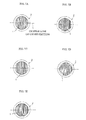
- Fig. 7 shows various types of wound and laminated iron cores 1 in cross section vertical to the peripheral direction of the ring.
- Fig. 7A shows elliptical shape
- Fig. 7B shows a hexagonal shape
- Fig. 7C shows a shape encircled by a pair of point-symmetrically positioned circular arcs with straight lines connecting respective edges of the pair of circular arcs on respective sides.
- Fig. 7D shows a square shape whose apexes comprise a circular arc.
- Fig. 7E shows an octagonal shape.
- These types of cross sectional shapes are formed by winding, for example, several hundreds of turns of the respective soft magnetic thin strips shown in Fig. 4B through Fig.
- Generally applied rectangular conductor wires have a ratio of thickness to width of around 1 : 5, and they are coated by a thin insulating film.
- any method for winding the rectangular conductor wire coil around the wound and laminated iron core may be applied. If the wound and laminated iron core is not divided, it is possible, for example, to feed the rectangular conductor wire using rolling mills while applying bending against the wound and laminated iron core, thus winding around the wound and laminated iron core. In the case that the wound and laminated iron core is divided into sections, it is possible to separately prepare the rectangular conductor wire coil wound in an upright orientation, and to insert the divided wound and laminated iron core 1 into the coil, and then to assemble the wound and laminated iron core.
- Applicable coils winding around the wound and laminated iron core include the above-described rectangular conductor wire, a round conductor wire (i.e., a circular cross section conductor wire) coil, and a litz wire coil.
- the rectangular conductor wire coil wound in an upright orientation is advantageous in reducing the alternating effective resistance by the skin effect and also in terms of space efficiency.
- the outer face of the wound and laminated iron core is covered by an insulating coating such as resin film, or is covered with an insulating plastic cover, and then the coil is wound thereon.
- Fig. 8A shows the case of a single gap
- Fig. 8B shows the case of two gaps
- Fig. 8C shows the case of four gaps.
- An increased number of gaps prevents the reduction in inductance at higher current, thus realizing a superior direct current convolutional characteristic of inductance.
- the gap 3 can be formed by cutting the wound and laminated iron core 1 by a grinder cutting method and the like. To keep the gap 3, an insulation material such as a plastic can be inserted into the gap 3.
- Fig. 9A and Fig. 9B show an example wherein the divided sections 17x and 17y of the wound and laminated iron core 1 are housed in a doughnut-shape plastic casing 14.
- Fig. 9A shows the plan view
- Fig. 9B shows a cross sectional view along line VI-VI in Fig. 9A.
- the plastic casing 14 comprises a pair of casing members 14a and 14b divided along the periphery of the doughnut-shape plastic casing 14. At two positions in the peripheral direction of each of the casing members 14a and 14b, respective separation plates 15 are located to separate housings 16x and 16y for housing respective divided sections 17x and 17y of the wound and laminated iron core 1.
- the divided sections 17x and 17y of the wound and laminated iron core 1 are housed in respective housings 16x and 16y, and the casing members 14a and 14b are connected to each other using an adhesive, a mechanical connecting means, or the like.
- a coil is wound around the plastic casing 14 which houses the divided sections 17x, 17y of the wound and laminated iron core 1.
- a separation plate is located at each of three or more positions in the peripheral direction of each of the casing members 14a and 14b, thus forming the housings 16 corresponding to the number of divisions of the wound and laminated iron core.
- Fig. 10A and Fig. 10B show another example of a doughnut-shape plastic casing 14 which houses a pair of divided sections 17x and 17y of the wound and laminated iron core 1.
- Fig. 10A is the plan view
- Fig. 10B is a cross sectional view along line VIII-VIII in Fig. 10A.
- the example shows a pair of divided casing members 14a and 14b along the periphery thereof.
- the example is the same as in the example of Figs. 9A and 9B in view of housing the pair of divided housing sections 17x and 17y of the wound and laminated iron core 1 in respective housing sections 16x and 16y, and in that the casing members 14a and 14b are connected to each other using an adhesive, a mechanical connecting means, and the like.
- the example adopts no separation plate inside of the casing members 14a and 14b, and forms a gap 3 between the divided sections 17x and 17y of the wound and laminated iron core by inserting an insulation material 18 such as a plastic.
- Fig. 11 shows an example where the plastics casing 14 comprises two casing members 14x and 14y which house respective divided sections 17x and 17y of the wound and laminated iron core 1, and where the ring-shaped plastic casing 14 is formed by connecting these casing members 14x and 14y to each other.
- the gap in the wound and laminated iron core is formed by the casing edges 140 at the joint of the casing members 14x and 14y.
- the casing members 14x and 14y are prepared by dividing the half doughnut-shape casing into two pieces along the periphery thereof.
- the casing members 14x and 14y are connected to each other using an adhesive, a mechanical means, or the like to form a ring-shaped plastic casing 14.
- the ring-shaped plastic casing 14 is prepared by preparing a number of casing members equal to the number of divisions of the wound and laminated iron core, and by connecting these casing members to each other.
- Applicable soft magnetic thin strips include an oriented or non-oriented silicon steel sheet containing less than 4 mass% Si, a high silicon steel sheet containing 4 to 7 mass% Si, and an amorphous steel sheet. Further reduced noise and loss are attained by using a silicon steel sheet containing an average of 4.0 to 7.0 mass% Si in a thickness direction thereof, preferably 6.2 to 6.9 mass%, and more preferably 6.65 mass%, or by using a silicon steel sheet containing 6.0 to 7.0 mass% Si in a surface layer thereof which is higher than the Si content in the center portion in the thickness direction by 0.5 mass% or more, wherein the distribution of Si content in the thickness direction is nearly symmetrical to the center of the thickness.
- this kind of steel sheet is manufactured from a steel sheet containing small amount of Si, less than 4 mass%, by siliconizing the steel sheet to penetrate Si into the surface layer thereof, then by diffusing the Si from the surface layer in the sheet thickness direction.
- the Si concentration may have constant distribution in the sheet thickness direction even if the Si content is nearly uniform in the sheet thickness direction.
- the thickness of silicon steel sheet is not specifically limited. However, it is preferable that the sheet thickness be around 0.02 to 0.1 mm for high frequency waves.
- the wound and laminated iron core of the reactor according to the present invention is formed by winding a soft magnetic thin strip in a circular ring shape or elliptical ring shape. Consequently, strain is hard to be induced when they are wound, and thus the iron core can be applied without providing strain relief annealing.
- a reactor having the above-described structure particularly a reactor having a gap therein
- electromagnetic force is induced when current is introduced to the coil, which induces the concentration of coiled wires to a portion where no gap exists on the wound and laminated iron core, which then results in movement of coiled wires to eliminate coiled wires from the gap portion on the wound and laminated iron core.
- the current varies, the movement of the coiled wires also varies, and the vibration on movement generates noise.
- it is effective to adhere and fix the coil to the wound and laminated iron core using a resin.
- the resin adhesion layer is formed on almost the entire outer periphery of the ring of the wound and laminated iron core, and that at least a part of the periphery of the coil is buried in the resin adhesion layer.
- the resin adhesion layer may be formed over the whole surface of the wound and laminated iron core, and the whole of the coil may be buried in the resin adhesion layer.
- the resin adhesion layer is formed on only about half the cross section of the wound and laminated iron core, and that about half of the coil periphery is buried in the resin adhesion layer, while the other approximately half portion thereof is exposed to air.
- This type of reactor is readily formed by placing the wound and laminated iron core wound with coil therearound in a container, and by filling a resin liquid in the container to harden and adhere the wound and laminated iron core to the container.
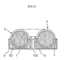
- Fig. 12 shows a cross sectional view of a reactor which has a wound and laminated iron core adhered and fixed to a container using a resin.
- the reactor body X comprises a wound and laminated iron core 1, and a coil 2 housed in an annular housing 90 of a shallow container 9 having an open top.
- the upper half of the reactor body X is exposed from the container 9.
- a resin adhesion layer 7 is formed in a portion corresponding to about half of the cross section of the wound and laminated iron core 1.
- About half of the periphery of the coil 2 is buried in the resin adhesion layer 7.
- the resin adhesion layer 7 surely prevents the movement of adjacent coils 2. And since the upper half of the reactor body X is protruded from the container 9 to be exposed to air, heat dissipation from the coil 2 is adequately achieved.
- the end leads of the coil 2 may be withdrawn in a lateral direction to the coil through, for example, a notch groove formed at top edge of the container 9, or may be withdrawn upright from the container 9 without forming such a notch groove.
- the container 9 also plays the role of fixing the body X, and is designed to be fixed to various types of equipment. To do this, at the center portion of the container 9, a mounting section 10 is provided to mount a fixing bolt or a fixing screw. The mounting section 10 is provided with a mounting hole 100. The container 9 which integrally fixes the reactor body X using a resin is then mounted to any of various kinds of equipment using a fixing bolt or a fixing screw attached to the mounting hole 100.
- the depth of the container 9 which houses the reactor body X may be arbitrarily selected, and, depending on the situation, the depth may be sufficient to hide most of or all of the reactor body X.
- a satisfactory depth of the container 9 is a depth which enables the coil 2 to be adhered and fixed to the wound and laminated iron core 1 using the resin adhesion layer 7 formed inside the container 9, and to prevent the movement of adjacent coil wires. An excessively deep container 9 may hinder the air flow against the coil 2.
- the depth of the container 9 is around 20 to 60% of the height of reactor body X (i.e., the height along the center axis of the ring-shaped reactor), and more preferably around 50%, so as to form the resin adhesion layer 7 only in the region corresponding to about half (i.e., the lower half) of the cross section of the wound and laminated iron core, which is shown in Fig. 12.
- the inner face of the container 9 may be formed to have a circular arc cross section responding to the outer shape of the coil 2 of the reactor body X.
- the material of container 9 may be arbitrarily selected. Normally, the container 9 is made of resin or the like.
- the resin On filling the resin in the container 9, if the resin also covers the upper half portion of the reactor body X exposed from the container 9 to form a thin film (coating by a thin film of resin layer), the upper portion of the coil 2 is also adhered and fixed to the wound and laminated iron core 1, which assures more firm fixation of the coil 2.
- the thin film resin layer that covers the upper half of the reactor body X may be, for example, formed in advance by applying a thin resin coating over the whole area of the reactor body X before housing the reactor body X in the container 9.
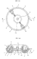
- Fig. 13A and Fig. 13B show another example of a reactor, in which the wound and laminated iron core is adhered and fixed using a resin.
- the circular ring-shaped wound and laminated iron core 1 and the rectangular conductor wire coil 2 wound in an upright orientation, which form the reactor body X, are fixed by the resin adhesion layer 7.
- the reactor body X is integrated with the fixer 4.
- the fixer 4 is a member in a dish-shape, comprising a mounting section 40 having a mounting hole 6 for mounting to any of various kinds of equipment using a fixing bolt or a fixing screw, and a housing 41 of the reactor body X, which is located outside of the mounting section 40.
- the housing 41 has an annular concavity 5 to house the lower half of the circular ring-shaped reactor body X.
- the depth of the concavity 5 is required to be deep enough to fill the resin to fix the reactor body X, which depth may be 20 to 50% of the height of the reactor body X, and preferably around 50%.
- the end leads 21 are withdrawn in a lateral direction to the reactor through respective notch grooves 42 formed at an upper edge of the housing 41.
- the direction of withdrawing the end leads 21 is arbitrary, and upright withdrawal may be applied.
- the coil 2, the wound and laminated iron core 1, and the fixer 4 are integrally adhered and fixed to each other via the resin adhesion layer 7.
- vibration noise is effectively suppressed.
- the resin in the concavity 5 if the resin also coats the upper portion of the reactor body X exposed from the concavity 5 in a thin resin film, this portion also adheres the coil 2 with the wound and laminated iron core 1, which further effectively prevents vibration noise.
- the thin film resin layer that coats the upper half of the reactor body X exposed from the concavity 5 may be prepared before mounting the reactor body X to the fixer 4 by, for example, applying thin resin coating to the whole surface of the reactor body X.
- a single fixing bolt or fixing screw 8 allows ready attachment to any of various kinds of equipment Y.
- Fig. 14A, Fig. 14B, and Fig. 15 show a further example of a reactor according to the present invention, particularly of the reactor using a container.
- Fig. 14A shows a plan view
- Fig. 14B shows a cross sectional view along line XIV-XIV in Fig. 14A
- Fig. 15 shows protrusions formed on the inner wall surface of the container.
- the example is a reactor having a separator function which insulates adjacent coil wires 20 in the container, which allows rectangular conductor wires having no insulation film to be used.
- the container 9 is a shallow container having an open top, similar to the one shown in Fig. 12, and has an annular housing 90 which houses the reactor body X therein.
- Each of the protrusions 19 is inserted between adjacent coil wires 20 to insulate adjacent portions of the coil wire 20 from each other.
- the coil 2 adopts a conductor wire having no insulation coating, no problem occurs.
- the coil formed by conductor wire without insulation coating is markedly inexpensive, thus significantly reducing the reactor cost.
- reactors use a magnetic core having a wound and laminated iron core prepared by winding a soft magnetic thin strip in a circular ring shape or in an elliptical ring shape.
- a reactor giving further low noise and loss and which is also easy to manufacture may also be prepared by using a block magnetic core such as ferritic core (sintered magnetic core) and dust core and by adhering the coil to the magnetic core using a resin.
- the reactor having a wound and laminated iron core according to the present invention also has the following advantages as compared with the conventional type reactors.
- the reactor according to the present invention can be applied in various kinds of power source equipment.
- the reactor according to the present invention is suitable for low noise and low loss inductance elements which are used in a main circuit to remove a harmonic wave current by introducing a specified frequency current and to convert into a dominant wave current at 50/60 Hz.
- the reactor according to the present invention is suitable for the inductance elements of: an inverter circuit mounted to a micro-gas turbine, a fuel cell power generator, a solar-electric power generator, a wind power generator, an air conditioner, a refrigerator, a no-break power unit, a booster converter circuit, and an EMI countermeasure circuit.
- a reactor according to the present invention having the structure shown in Fig. 2 and Fig. 3, and a conventional type reactor shown in Fig. 1 were separately prepared. For each of the reactors, the direct current convolutional characteristic of inductance was tested.
- the reactor according to the present invention comprised a wound and laminated iron core formed by winding a soft magnetic thin strip in a circular ring shape, and a rectangular conductor wire wound in an upright orientation around the wound and laminated iron core over almost the entire periphery thereof.
- the wound and laminated iron core had a circular cross section vertical to the periphery of the ring, and a pair of point-symmetrically positioned gaps of 2.25 mm.
- the conventional type reactor comprised a laminated iron core having a square cross section, and a pair of rectangular conductor wires wound in an upright orientation around the core sections facing each other on the laminated iron core.
- the coil of each reactor was made of a rectangular conductor wire having 5 mm in width and 0.9 mm in thickness, with 20 mm in inner coiling diameter and 76 turns.
- Fig. 16 shows the direct current convolutional characteristic of inductance for the reactors.
- the inductance of the reactor according to the present invention was 440 ⁇ H/30 A, which is larger than the 320 ⁇ H/30 A inductance of the conventional type reactor.
- a reactor according to the present invention having a similar structure with that in Example 1 was prepared using a rectangular conductor wire of 4 mm in width and 0.68 mm in thickness, with 20 mm in inner coiling diameter and 76 turns.
- Example 2 a conventional type reactor having a similar structure with that in Example 1 was prepared using a rectangular conductor wire of 5 mm in width and 0.9 mm in thickness, with 20 mm in inner coiling diameter and 76 turns.
- Fig. 17 shows the alternating effective resistance characteristic of the reactors.
- the alternating effective resistance of the reactor according to the present invention was 3.6 ⁇ /20 A, which is significantly smaller than the 5.1 ⁇ /20 A of the conventional type reactor, with less coil cross sectional area in the reactor of the present invention. Therefore, the reactor according to the present invention achieves size reduction and weight reduction.
Landscapes
- Engineering & Computer Science (AREA)
- Power Engineering (AREA)
- Microelectronics & Electronic Packaging (AREA)
- Coils Of Transformers For General Uses (AREA)
- Soft Magnetic Materials (AREA)
- Housings And Mounting Of Transformers (AREA)
Applications Claiming Priority (6)
| Application Number | Priority Date | Filing Date | Title |
|---|---|---|---|
| JP2000114991 | 2000-04-17 | ||
| JP2000114991 | 2000-04-17 | ||
| JP2000324003 | 2000-10-24 | ||
| JP2000324003 | 2000-10-24 | ||
| JP2001022217A JP3794928B2 (ja) | 2000-04-17 | 2001-01-30 | 低騒音・低損失リアクトル |
| JP2001022217 | 2001-01-30 |
Publications (3)
| Publication Number | Publication Date |
|---|---|
| EP1148522A2 true EP1148522A2 (fr) | 2001-10-24 |
| EP1148522A3 EP1148522A3 (fr) | 2001-12-12 |
| EP1148522B1 EP1148522B1 (fr) | 2009-02-18 |
Family
ID=27343103
Family Applications (1)
| Application Number | Title | Priority Date | Filing Date |
|---|---|---|---|
| EP01109357A Expired - Lifetime EP1148522B1 (fr) | 2000-04-17 | 2001-04-17 | Réactance à faible perte et à faible bruit |
Country Status (6)
| Country | Link |
|---|---|
| US (1) | US6531946B2 (fr) |
| EP (1) | EP1148522B1 (fr) |
| JP (1) | JP3794928B2 (fr) |
| KR (1) | KR100368900B1 (fr) |
| DE (1) | DE60137661D1 (fr) |
| TW (1) | TW494415B (fr) |
Cited By (4)
| Publication number | Priority date | Publication date | Assignee | Title |
|---|---|---|---|---|
| EP1732187A1 (fr) * | 2005-06-08 | 2006-12-13 | Renault | Bougie à plasma radiofréquence pour l'allumage commandé de moteurs à combustion interne |
| EP1801822A3 (fr) * | 2005-12-22 | 2009-08-05 | Samsung Electronics Co.,Ltd. | Dispositif inducteur, carte de circuit imprimé et appareil électronique l'utilisant |
| CN106531423A (zh) * | 2016-12-30 | 2017-03-22 | 青岛云路新能源科技有限公司 | 一种矩形金属粉芯电感 |
| CN109564814A (zh) * | 2016-08-09 | 2019-04-02 | 三菱电机株式会社 | 空芯型电抗器单元及具有空芯型电抗器单元的电源装置 |
Families Citing this family (48)
| Publication number | Priority date | Publication date | Assignee | Title |
|---|---|---|---|---|
| US6664689B2 (en) * | 2001-08-06 | 2003-12-16 | Mitchell Rose | Ring-shaped motor core with toroidally-wound coils |
| JP2006505125A (ja) * | 2002-11-01 | 2006-02-09 | マグテック エーエス | 結合装置 |
| US20040217838A1 (en) * | 2003-04-29 | 2004-11-04 | Lestician Guy J. | Coil device |
| JP4544897B2 (ja) * | 2004-04-06 | 2010-09-15 | 満男 海老澤 | コイル及びコイル製造装置 |
| US7808359B2 (en) * | 2005-10-21 | 2010-10-05 | Rao Dantam K | Quad-gapped toroidal inductor |
| JP2008060495A (ja) * | 2006-09-04 | 2008-03-13 | Fuji Electric Holdings Co Ltd | リアクトルおよびリアクトルを用いたノイズフィルタ |
| US7746211B2 (en) * | 2006-12-27 | 2010-06-29 | General Electric Company | Lamp transformer assembly |
| JP4867889B2 (ja) * | 2007-01-18 | 2012-02-01 | 株式会社デンソー | 電力変換装置及びその製造方法 |
| JP5343387B2 (ja) * | 2008-03-31 | 2013-11-13 | 住友電気工業株式会社 | リアクトル、及びコンバータ |
| JP5029482B2 (ja) * | 2008-04-25 | 2012-09-19 | 株式会社豊田自動織機 | リアクトル装置 |
| JP2010147199A (ja) * | 2008-12-18 | 2010-07-01 | Totoku Electric Co Ltd | 編組線トロイダルコイル |
| JP4905470B2 (ja) * | 2009-01-14 | 2012-03-28 | ダイキン工業株式会社 | トロイダルコイルおよび空気調和機のコントローラ |
| KR100980484B1 (ko) * | 2010-04-09 | 2010-09-07 | (주)인텍에프에이 | 환형 코어 리액터를 구비한 회생 에너지 피드백 장치 |
| JP2011249699A (ja) * | 2010-05-31 | 2011-12-08 | Sht Co Ltd | 磁気コア装置及びこれを用いたコイル装置 |
| WO2011161769A1 (fr) * | 2010-06-22 | 2011-12-29 | トヨタ自動車株式会社 | Réacteur et son procédé de fabrication |
| US8461955B2 (en) | 2010-06-22 | 2013-06-11 | Toyota Jidosha Kabushiki Kaisha | Reactor and reactor manufacturing method |
| JP5867677B2 (ja) * | 2010-07-13 | 2016-02-24 | 住友電気工業株式会社 | リアクトル、コンバータ及び電力変換装置 |
| JP5208187B2 (ja) * | 2010-11-30 | 2013-06-12 | 三菱電機株式会社 | リアクトル装置 |
| US20130027112A1 (en) * | 2011-07-29 | 2013-01-31 | Yen-Wei Hsu | Inductor |
| CN103035362A (zh) * | 2011-10-10 | 2013-04-10 | 上海良治电器技术有限公司 | 一种新型电抗器 |
| US9824818B2 (en) | 2011-10-19 | 2017-11-21 | Keith D. Earhart | Method of manufacturing wound transformer core |
| US20140111297A1 (en) * | 2012-10-18 | 2014-04-24 | Manufacturing Systems and Equipment Inc. | Wound transformer core and method of manufacture |
| JP5958792B2 (ja) * | 2012-01-24 | 2016-08-02 | 住友電気工業株式会社 | リアクトル、コンバータ、及び電力変換装置 |
| JP6032460B2 (ja) * | 2012-03-15 | 2016-11-30 | パナソニックIpマネジメント株式会社 | パワーコンディショナ |
| US20140016357A1 (en) * | 2012-07-12 | 2014-01-16 | Yen-Wei Hsu | Power Regenerator |
| JP6283976B2 (ja) * | 2013-01-16 | 2018-02-28 | 日立金属株式会社 | コモンモードチョーク |
| CN103489568A (zh) * | 2013-09-25 | 2014-01-01 | 苏州康开电气有限公司 | 散热性能良好的电抗器 |
| CN103489585A (zh) * | 2013-09-25 | 2014-01-01 | 苏州康开电气有限公司 | 高散热性环保变压器 |
| US20150310984A1 (en) * | 2014-04-25 | 2015-10-29 | MAGicALL, Inc. | Enclosed multiple-gap core inductor |
| KR102116807B1 (ko) * | 2014-05-27 | 2020-06-01 | 후지 덴키 가부시키가이샤 | 권선 부품의 부착 구조 및 이 부착 구조를 구비한 전력 변환 장치 |
| JP2016018929A (ja) * | 2014-07-09 | 2016-02-01 | Necトーキン株式会社 | リアクトル及びこれを用いた直流電圧変換装置 |
| JP6095723B2 (ja) * | 2015-06-03 | 2017-03-15 | 株式会社エス・エッチ・ティ | ギャップ付きコア、これを用いたコイル部品及びコイル部品の製造方法 |
| CN105006350A (zh) * | 2015-06-12 | 2015-10-28 | 无锡希恩电气有限公司 | 大功率电抗器铁芯 |
| JP6418454B2 (ja) * | 2015-12-10 | 2018-11-07 | 株式会社オートネットワーク技術研究所 | リアクトル |
| JP2017175017A (ja) * | 2016-03-24 | 2017-09-28 | パナソニックIpマネジメント株式会社 | リアクトル |
| JP2018037597A (ja) * | 2016-09-02 | 2018-03-08 | 株式会社日立製作所 | 静止誘導電器 |
| CN106403182B (zh) | 2016-09-21 | 2018-11-30 | 珠海格力电器股份有限公司 | 一种光伏空调系统的控制参数确定方法、装置和控制系统 |
| EP3330983B1 (fr) * | 2016-11-30 | 2023-10-04 | Danfoss Editron Oy | Dispositif inductif |
| JP7176174B2 (ja) * | 2017-04-07 | 2022-11-22 | スミダコーポレーション株式会社 | コイル部品用コア、及び、コイル部品 |
| CN107146709A (zh) * | 2017-07-10 | 2017-09-08 | 江西大族能源科技股份有限公司 | 单相卷铁芯四段七级等长开料法 |
| US10784673B2 (en) * | 2017-08-18 | 2020-09-22 | Varian Semiconductor Equipment Associates, Inc. | Current protection device with mutual reactor |
| JP6251838B1 (ja) * | 2017-09-11 | 2017-12-20 | 高周波熱錬株式会社 | 出力電流合成装置及び電力供給装置 |
| DE102017126473A1 (de) * | 2017-11-10 | 2019-05-16 | Abb Schweiz Ag | Transformator zur Verwendung in einem Schienenfahrzeug |
| CN111819644B (zh) * | 2018-03-15 | 2022-03-04 | 三菱电机株式会社 | 电抗器 |
| CN108847347A (zh) * | 2018-08-03 | 2018-11-20 | 青岛云路先进材料技术有限公司 | 一种非晶带材连续开料的方法和一种多级料带 |
| CN109366263B (zh) * | 2018-10-03 | 2024-08-27 | 淮北宇光纺织器材有限公司 | 一种针布冲齿刀模的磁极强力磨削吸盘 |
| JP7192815B2 (ja) * | 2020-03-16 | 2022-12-20 | 株式会社村田製作所 | インダクタ部品 |
| CN111431158B (zh) * | 2020-04-23 | 2021-11-05 | 佛山科学技术学院 | 一种真空断路器过电压组合抑制系统及装置 |
Citations (1)
| Publication number | Priority date | Publication date | Assignee | Title |
|---|---|---|---|---|
| EP0676776A1 (fr) | 1994-03-16 | 1995-10-11 | Kitamura Kiden Co., Ltd. | Noyau enroulé pour transformateur torique |
Family Cites Families (24)
| Publication number | Priority date | Publication date | Assignee | Title |
|---|---|---|---|---|
| US3210701A (en) * | 1962-05-14 | 1965-10-05 | Automatic Elect Lab | Wound toroidal core shell |
| JPS5517459Y2 (fr) * | 1975-04-30 | 1980-04-23 | ||
| NZ191840A (en) * | 1978-10-19 | 1983-06-14 | L Manderson | Transformer core construction |
| US4427462A (en) * | 1981-06-18 | 1984-01-24 | Matsushita Electric Industrial Co., Ltd. | Electric apparatus and its magnetic core of (100)[011] silicon-iron sheet made by rapid quenching method |
| JPS61174720U (fr) * | 1985-04-22 | 1986-10-30 | ||
| JPS62147713A (ja) * | 1985-12-23 | 1987-07-01 | Sawafuji Electric Co Ltd | 巻鉄心の成形装置 |
| JPH0658782B2 (ja) * | 1986-10-07 | 1994-08-03 | 三菱電機株式会社 | サ−マルリレ−用飽和リアクトル |
| EP0269347B1 (fr) * | 1986-11-22 | 1993-01-20 | Kitamura Kiden Co., Ltd. | Noyau enroulé dont la section présente une périphérie ayant des portions circulaires et elliptiques |
| JPH01143112U (fr) * | 1988-03-27 | 1989-10-02 | ||
| JPH0338603U (fr) * | 1989-08-24 | 1991-04-15 | ||
| US4975672A (en) * | 1989-11-30 | 1990-12-04 | The United States Of America As Represented By The Administrator Of The National Aeronautics And Space Administration | High power/high frequency inductor |
| JPH0443622A (ja) * | 1990-06-11 | 1992-02-13 | Matsushita Electric Works Ltd | チョークコイル |
| US5165162A (en) * | 1990-12-24 | 1992-11-24 | General Electric Company | Method for making a segmented toroidal inductor |
| JPH0541327A (ja) * | 1991-08-05 | 1993-02-19 | Denki Tetsushin Kogyo Kk | 巻鉄心の製法 |
| US5871662A (en) * | 1993-05-11 | 1999-02-16 | U.S. Philips Corporation | Sintered transformer or inductor core of nizn ferrite material |
| JP2602204Y2 (ja) * | 1993-09-20 | 2000-01-11 | 松下電工株式会社 | 電磁装置 |
| JPH07263261A (ja) * | 1994-03-22 | 1995-10-13 | Tdk Corp | インダクタンス素子並びにインダクタンス素子の製造方法及び該インダクタンス素子に用いるコアケース |
| JPH08222455A (ja) * | 1995-02-13 | 1996-08-30 | Tokin Corp | ノーマルモードチョークコイル |
| JPH08339932A (ja) * | 1995-06-12 | 1996-12-24 | Mitsui Petrochem Ind Ltd | 磁 心 |
| JPH1174135A (ja) * | 1997-08-27 | 1999-03-16 | Hitachi Ferrite Electronics Ltd | 高圧トランス |
| JPH1174138A (ja) * | 1997-08-27 | 1999-03-16 | Hitachi Ferrite Electronics Ltd | 高圧トランス |
| JP2000045053A (ja) * | 1998-07-29 | 2000-02-15 | Nkk Corp | 鉄損の低い方向性珪素鋼板 |
| JP2000040626A (ja) * | 1998-07-24 | 2000-02-08 | Matsushita Electric Ind Co Ltd | チョークコイル |
| JP3952606B2 (ja) * | 1998-08-19 | 2007-08-01 | Jfeスチール株式会社 | 磁気特性および被膜特性に優れた方向性電磁鋼板およびその製造方法 |
-
2001
- 2001-01-30 JP JP2001022217A patent/JP3794928B2/ja not_active Expired - Lifetime
- 2001-04-06 KR KR10-2001-0018128A patent/KR100368900B1/ko not_active Expired - Fee Related
- 2001-04-16 TW TW090109020A patent/TW494415B/zh not_active IP Right Cessation
- 2001-04-17 EP EP01109357A patent/EP1148522B1/fr not_active Expired - Lifetime
- 2001-04-17 US US09/836,380 patent/US6531946B2/en not_active Expired - Lifetime
- 2001-04-17 DE DE60137661T patent/DE60137661D1/de not_active Expired - Lifetime
Patent Citations (1)
| Publication number | Priority date | Publication date | Assignee | Title |
|---|---|---|---|---|
| EP0676776A1 (fr) | 1994-03-16 | 1995-10-11 | Kitamura Kiden Co., Ltd. | Noyau enroulé pour transformateur torique |
Cited By (7)
| Publication number | Priority date | Publication date | Assignee | Title |
|---|---|---|---|---|
| EP1732187A1 (fr) * | 2005-06-08 | 2006-12-13 | Renault | Bougie à plasma radiofréquence pour l'allumage commandé de moteurs à combustion interne |
| FR2887083A1 (fr) * | 2005-06-08 | 2006-12-15 | Renault Sas | Bougie a plasma radiofrequence pour l'allumage commande de moteurs a combustion interne |
| EP1801822A3 (fr) * | 2005-12-22 | 2009-08-05 | Samsung Electronics Co.,Ltd. | Dispositif inducteur, carte de circuit imprimé et appareil électronique l'utilisant |
| US7868722B2 (en) | 2005-12-22 | 2011-01-11 | Samsung Electronics Co., Ltd. | Inductor apparatus, circuit board, and electronic device using the same |
| CN109564814A (zh) * | 2016-08-09 | 2019-04-02 | 三菱电机株式会社 | 空芯型电抗器单元及具有空芯型电抗器单元的电源装置 |
| CN106531423A (zh) * | 2016-12-30 | 2017-03-22 | 青岛云路新能源科技有限公司 | 一种矩形金属粉芯电感 |
| CN106531423B (zh) * | 2016-12-30 | 2019-04-09 | 青岛云路新能源科技有限公司 | 一种矩形金属粉芯电感 |
Also Published As
| Publication number | Publication date |
|---|---|
| JP2002203729A (ja) | 2002-07-19 |
| TW494415B (en) | 2002-07-11 |
| EP1148522A3 (fr) | 2001-12-12 |
| DE60137661D1 (de) | 2009-04-02 |
| JP3794928B2 (ja) | 2006-07-12 |
| US20010030594A1 (en) | 2001-10-18 |
| EP1148522B1 (fr) | 2009-02-18 |
| KR100368900B1 (ko) | 2003-01-24 |
| US6531946B2 (en) | 2003-03-11 |
| KR20010103595A (ko) | 2001-11-23 |
Similar Documents
| Publication | Publication Date | Title |
|---|---|---|
| US6531946B2 (en) | Low noise and low loss reactor | |
| EP2455953B1 (fr) | Réacteur | |
| US8749195B2 (en) | Contactless charging module, contactless charging device, and method of manufacturing contactless charging module | |
| EP2546999B1 (fr) | Dispositif de transport d'énergie sans fil pour système de communication d'énergie sans fil | |
| JP2011211176A (ja) | 無線電力伝送用磁気素子及び電力供給装置 | |
| KR100292596B1 (ko) | 적층형 압전 트랜스포머 및 그 제조 방법 | |
| JP2009252787A (ja) | コイル部品 | |
| JPH0722258A (ja) | リアクタ及びその製造方法 | |
| JP4962634B1 (ja) | 非接触充電モジュールの製造方法 | |
| JP7840395B2 (ja) | 平面トランス用のプリント回路基板の集積共振能力 | |
| JP5045858B1 (ja) | 非接触充電モジュールの製造方法及び非接触充電モジュール | |
| JPH11265833A (ja) | 点火コイル用コア及び該コアの製造方法 | |
| JP7809940B2 (ja) | コイル部品、送電装置、受電装置、及び電力伝送システム | |
| KR100701906B1 (ko) | 와이어 코어 유도 디바이스들을 이용하는 전력 변환 시스템 | |
| JP2006100513A (ja) | リアクトル | |
| JPH0311534B2 (fr) | ||
| EP4600977A1 (fr) | Inducteur en mode différentiel pour applications de filtrage aérospatial haute puissance | |
| KR101373689B1 (ko) | 중소형 ac, dc 고주파리액터 | |
| JP6018763B2 (ja) | リアクトル | |
| JPH07211549A (ja) | 電磁装置 | |
| JP2001307931A (ja) | 変圧器 | |
| KR101333055B1 (ko) | 발전기 및 그 제조방법 | |
| JPH0429542Y2 (fr) | ||
| CN1082233C (zh) | 扼流圈及其制造方法 | |
| KR20170127237A (ko) | 인덕터 및 이의 제조 방법 |
Legal Events
| Date | Code | Title | Description |
|---|---|---|---|
| PUAI | Public reference made under article 153(3) epc to a published international application that has entered the european phase |
Free format text: ORIGINAL CODE: 0009012 |
|
| 17P | Request for examination filed |
Effective date: 20010417 |
|
| AK | Designated contracting states |
Kind code of ref document: A2 Designated state(s): DE FR GB Kind code of ref document: A2 Designated state(s): AT BE CH CY DE DK ES FI FR GB GR IE IT LI LU MC NL PT SE TR |
|
| AX | Request for extension of the european patent |
Free format text: AL;LT;LV;MK;RO;SI |
|
| PUAL | Search report despatched |
Free format text: ORIGINAL CODE: 0009013 |
|
| AK | Designated contracting states |
Kind code of ref document: A3 Designated state(s): AT BE CH CY DE DK ES FI FR GB GR IE IT LI LU MC NL PT SE TR |
|
| AX | Request for extension of the european patent |
Free format text: AL;LT;LV;MK;RO;SI |
|
| AKX | Designation fees paid |
Free format text: DE FR GB |
|
| RAP1 | Party data changed (applicant data changed or rights of an application transferred) |
Owner name: JFE STEEL CORPORATION |
|
| 17Q | First examination report despatched |
Effective date: 20071114 |
|
| GRAP | Despatch of communication of intention to grant a patent |
Free format text: ORIGINAL CODE: EPIDOSNIGR1 |
|
| RIN1 | Information on inventor provided before grant (corrected) |
Inventor name: KITAMURA, FUMIO Inventor name: TATSUNO, MICHIO Inventor name: ABE, MASAHIRO,N |
|
| GRAS | Grant fee paid |
Free format text: ORIGINAL CODE: EPIDOSNIGR3 |
|
| GRAA | (expected) grant |
Free format text: ORIGINAL CODE: 0009210 |
|
| AK | Designated contracting states |
Kind code of ref document: B1 Designated state(s): DE FR GB |
|
| REG | Reference to a national code |
Ref country code: GB Ref legal event code: FG4D |
|
| REF | Corresponds to: |
Ref document number: 60137661 Country of ref document: DE Date of ref document: 20090402 Kind code of ref document: P |
|
| PLBE | No opposition filed within time limit |
Free format text: ORIGINAL CODE: 0009261 |
|
| STAA | Information on the status of an ep patent application or granted ep patent |
Free format text: STATUS: NO OPPOSITION FILED WITHIN TIME LIMIT |
|
| 26N | No opposition filed |
Effective date: 20091119 |
|
| REG | Reference to a national code |
Ref country code: FR Ref legal event code: PLFP Year of fee payment: 16 |
|
| REG | Reference to a national code |
Ref country code: FR Ref legal event code: PLFP Year of fee payment: 17 |
|
| REG | Reference to a national code |
Ref country code: FR Ref legal event code: PLFP Year of fee payment: 18 |
|
| PGFP | Annual fee paid to national office [announced via postgrant information from national office to epo] |
Ref country code: FR Payment date: 20190313 Year of fee payment: 19 |
|
| PGFP | Annual fee paid to national office [announced via postgrant information from national office to epo] |
Ref country code: DE Payment date: 20190402 Year of fee payment: 19 |
|
| PGFP | Annual fee paid to national office [announced via postgrant information from national office to epo] |
Ref country code: GB Payment date: 20190417 Year of fee payment: 19 |
|
| REG | Reference to a national code |
Ref country code: DE Ref legal event code: R119 Ref document number: 60137661 Country of ref document: DE |
|
| PG25 | Lapsed in a contracting state [announced via postgrant information from national office to epo] |
Ref country code: DE Free format text: LAPSE BECAUSE OF NON-PAYMENT OF DUE FEES Effective date: 20201103 Ref country code: FR Free format text: LAPSE BECAUSE OF NON-PAYMENT OF DUE FEES Effective date: 20200430 |
|
| GBPC | Gb: european patent ceased through non-payment of renewal fee |
Effective date: 20200417 |
|
| PG25 | Lapsed in a contracting state [announced via postgrant information from national office to epo] |
Ref country code: GB Free format text: LAPSE BECAUSE OF NON-PAYMENT OF DUE FEES Effective date: 20200417 |