EP1158836A2 - Strahlungsanordnung sowie deren Verwendung und Verfahren zur Behandlung von Oberflächen - Google Patents
Strahlungsanordnung sowie deren Verwendung und Verfahren zur Behandlung von Oberflächen Download PDFInfo
- Publication number
- EP1158836A2 EP1158836A2 EP01108725A EP01108725A EP1158836A2 EP 1158836 A2 EP1158836 A2 EP 1158836A2 EP 01108725 A EP01108725 A EP 01108725A EP 01108725 A EP01108725 A EP 01108725A EP 1158836 A2 EP1158836 A2 EP 1158836A2
- Authority
- EP
- European Patent Office
- Prior art keywords
- radiation
- arrangement according
- radiator
- tube
- range
- Prior art date
- Legal status (The legal status is an assumption and is not a legal conclusion. Google has not performed a legal analysis and makes no representation as to the accuracy of the status listed.)
- Granted
Links
Images




Classifications
-
- H—ELECTRICITY
- H05—ELECTRIC TECHNIQUES NOT OTHERWISE PROVIDED FOR
- H05B—ELECTRIC HEATING; ELECTRIC LIGHT SOURCES NOT OTHERWISE PROVIDED FOR; CIRCUIT ARRANGEMENTS FOR ELECTRIC LIGHT SOURCES, IN GENERAL
- H05B3/00—Ohmic-resistance heating
- H05B3/40—Heating elements having the shape of rods or tubes
- H05B3/42—Heating elements having the shape of rods or tubes non-flexible
- H05B3/44—Heating elements having the shape of rods or tubes non-flexible heating conductor arranged within rods or tubes of insulating material
-
- H—ELECTRICITY
- H05—ELECTRIC TECHNIQUES NOT OTHERWISE PROVIDED FOR
- H05B—ELECTRIC HEATING; ELECTRIC LIGHT SOURCES NOT OTHERWISE PROVIDED FOR; CIRCUIT ARRANGEMENTS FOR ELECTRIC LIGHT SOURCES, IN GENERAL
- H05B3/00—Ohmic-resistance heating
- H05B3/0033—Heating devices using lamps
- H05B3/0038—Heating devices using lamps for industrial applications
- H05B3/0066—Heating devices using lamps for industrial applications for photocopying
-
- H—ELECTRICITY
- H05—ELECTRIC TECHNIQUES NOT OTHERWISE PROVIDED FOR
- H05B—ELECTRIC HEATING; ELECTRIC LIGHT SOURCES NOT OTHERWISE PROVIDED FOR; CIRCUIT ARRANGEMENTS FOR ELECTRIC LIGHT SOURCES, IN GENERAL
- H05B3/00—Ohmic-resistance heating
- H05B3/10—Heating elements characterised by the composition or nature of the materials or by the arrangement of the conductor
- H05B3/12—Heating elements characterised by the composition or nature of the materials or by the arrangement of the conductor characterised by the composition or nature of the conductive material
- H05B3/14—Heating elements characterised by the composition or nature of the materials or by the arrangement of the conductor characterised by the composition or nature of the conductive material the material being non-metallic
- H05B3/145—Carbon only, e.g. carbon black, graphite
-
- H—ELECTRICITY
- H05—ELECTRIC TECHNIQUES NOT OTHERWISE PROVIDED FOR
- H05B—ELECTRIC HEATING; ELECTRIC LIGHT SOURCES NOT OTHERWISE PROVIDED FOR; CIRCUIT ARRANGEMENTS FOR ELECTRIC LIGHT SOURCES, IN GENERAL
- H05B2203/00—Aspects relating to Ohmic resistive heating covered by group H05B3/00
- H05B2203/032—Heaters specially adapted for heating by radiation heating
Definitions
- the invention relates to a radiation arrangement with at least one infrared radiator and at least one further radiator with at least two elongated, permeable to light and IR radiation and to the surrounding atmosphere closed, cladding tubes, of which at least a first cladding tube one Has filament that has sealed tube ends and outer contacts with an outer Power supply is electrically connected, its use and a method for the treatment of surfaces.
- Infrared emitters are also known from EP 0 428 835 A2 and the corresponding US Pat. No. 5,091,632 known with twin tube spotlights.
- an infrared radiator with a carbon band use as a heating element; such a carbon band is especially for sale of IR radiation in a medium wavelength range from 1.5 to 4.5 ⁇ m.
- the invention has for its object to provide a thermal radiation arrangement coatings or prints with pigments or colors on surfaces Drying solvents quickly and at the same time the solvents, such as toluene or let water evaporate quickly.
- the object is achieved in that at least one second cladding tube is provided, which has a radiator tape, which also has sealed ends and external contacts with the or with a further external energy supply electrically connected is.
- the second cladding tube is also used to emit infrared radiation, in particular for the output of IR radiation in the middle IR range. It can of course, a different type of temperature radiator instead of the radiator belt are used, which emits radiation in the middle IR range.
- the arrangement is in the visible spectral range as well as near infrared radiation range, in particular with a wavelength in the range from 780 nm to 1.4 ⁇ m, as also has relatively high levels of radiation in the middle IR radiation range, in particular with a wavelength in the range from 2.5 ⁇ m to 5 ⁇ m.
- an elongated one is used as the radiator band
- Carbon tape used is also formed as an elongated spiral. It emits radiation in a medium IR spectral range off, while a filament lamp emits short-wave IR radiation (near IR) and, if necessary, also emits visible light.
- the radiation arrangement has different Planck distributions due to its superposition as a percentage more IR radiation components than previous radiation sources with only one Temperature in the specified wavelength ranges.
- thermal radiation sources at least one additional elongated one that is permeable to light and UV radiation Provide tube which has an electrical discharge path and a outputs additional UV radiation in the wavelength range from 0.15 to 380 nm, which in particular is suitable for drying paint.
- the reduced space requirement compared to individual radiators has proven to be particularly advantageous, by an optional operation of the radiation sources with different wavelengths optimal radiation conditions are set for the respective application areas can.
- the object is achieved in a method for treating surfaces by means of IR radiation, especially of coated or printed surfaces on substrates or irradiated with dissolved color pigments on a support for drying, thereby solved that the surface at least temporarily with an IR radiation with a high proportion in a first wavelength range from 780 nm to 1.2 ⁇ m and at least at times simultaneously with an IR radiation with a high radiation component in a second Wavelength range from 2.5 microns to 5 microns is treated.
- a major advantage is the fact that, depending on the embodiment, the individual radiation components of this radiation arrangement can be switched on in an OR combination or operated in a common switching mode. When operating machines with changing processes, this has the advantage that there is no longer a need to change the lamp. The user also no longer needs different individual emitter sources, so that a reduction in the spare parts inventory is achieved.
- the carbon emitter used can be used as a starting current limiter for the short-wave emitter (incandescent filament).
- UV radiation components can also be overlaid with the IR spectra become.
- separate and common operating modes can be combined.
- FIG. 1a schematically shows a twin tube radiator according to the invention in a perspective view.
- FIG. 1b shows a twin tube radiator in a front view, but one that is coiled Has carbon emitter.
- FIG. 1c shows a frontal view of an arrangement which additionally has a tubular discharge lamp has, so that in addition to infrared radiation, UV radiation is also generated can.
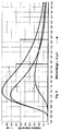
- Figure 2 shows in the diagram the relative intensity of a spectral radiation distribution according to Planck with KW / m 2 nomination with a short-wave infrared radiator (NIR / IR-A) at an operating temperature of 2600 ° C and a carbon radiator at an operating temperature of approx. 950 ° C , the intensity being plotted against the wavelength lambda [ ⁇ m].
- NIR / IR-A short-wave infrared radiator
- FIG. 3 shows the spectral absorption of the water for different layer thicknesses in the diagram (2 ⁇ m; 10 ⁇ m), with absorption ranging from 0 to 100 percent over the wavelength Lambda is plotted in ⁇ m.
- FIG. 4 shows the efficiency of water drying for a layer of 10 ⁇ m in the diagram Thickness, with temperature in Kelvin plotted along the X axis, while efficiency is entered along the Y axis.
- the radiation arrangement has a twin tube radiator 1, which has two Cladding tubes 2, 3 arranged at least approximately parallel to one another for infrared radiation and visible radiation contains transparent material, preferably quartz glass, the two tubes through an intermediate web 4, which is also made of quartz glass, are mechanically firmly connected.
- the first tube 2 has one with a Incandescent 5 provided short-wave infrared radiator, the high radiation intensity is in the wavelength range from 780 nm to approx. 1.2 ⁇ m (near IR / IR-A), as from the following Figure 2 (curve II) emerges.
- the definition of the wavelength range results derives from DIN standard 5030, part 2.
- a similar radiator is known, for example, from EP 0 428 835 and that mentioned at the beginning corresponding US 5,091,632 known.
- the incandescent filament 5 of the cladding tube 2 via leaf-shaped current feedthroughs 6, 7 made of molybdenum in the respective pinching area of the tube ends 8 ', 9' of tube 2 with each an outer connection contact 8, 9 electrically and mechanically connected to electrical connection with an external power supply.
- the tube 3 points against it an infrared radiator with a carbon band as the radiator band 10, which over Terminal contacts 11, 12 and leaf-shaped bushings 13, 14 made of molybdenum in respective squeezing area of the pipe ends 15, 16 with external connection contacts 17, 18 is provided for connection to the power supply.
- connection between the ends of the carbon band 11 and the current feedthroughs 13, 14 is preferably made of graphite paper, as described, for example, in DE 44 19 285 C2 or the corresponding US 5,567,951 is known. In this way, the lengthways pronounced electrical conductivity of the carbon tape when contacting Power supply can be balanced. It will also improve Cooling achieved.
- FIG. 1b shows the two cladding tubes 2 lying next to one another and 3 of the twin tube radiator 1, which are connected to one another via an intermediate web 4 made of quartz glass are connected.
- the emitter band 10 ' according to FIG. 1b is introduced into the Carbon emitter coiled, i.e. that a spiral helix serves as the radiator band 10 '.
- the coiled emitter band 10 has the particular advantage that a larger proportion of radiation in the wavelength range from 1.6 to 3.8 ⁇ m (near IR / IR-B to medium IR / IR-C) can be emitted according to curve 1 of Figure 2, as it is from the Stefan-Boltzmannschen Law results.
- the definition of the wavelength range results from the DIN standard 5030, part 2.
- connection contacts 8, 9, 17 '17 “and 18', 18" correspond in their function largely the contacts 17, 18 explained with reference to FIG. 1. Due to the separate connection contacts, there is a single control of the respective lamps possible, so that they can, for example, simultaneously or also can be operated alternately.
- FIG. 1c The frontal view of a lamp combination shown in FIG. 1c shows next to the one above described twin arrangement an additional switched as a discharge lamp Radiator arrangement, which is additionally connected via an intermediate web 4 '(quartz glass) Cladding tube 19 made of quartz glass allows the discharge lamp to emit UV radiation. Since the discharge lamp 20 via the intermediate web 4 'with the twin-tube lamp arrangement 1 'is connected, it can also be referred to as a triple tube radiator arrangement become. It is therefore possible to use colored light through visible light and infrared radiation to treat, and at the same time or alternating photoinitiators by means of UV radiation to be treated by discharge lamp 20.
- the filling of the discharge lamp 20 consists preferably of mercury and possibly an admixture of metal halides, the electrodes 21, 22 are preferably made of tungsten.
- the energy supply Discharge lamp 20 takes place via current feedthroughs 23, 24, which are preferably as Molybdenum foils are formed.
- the additional cladding tube 19 of the discharge lamp 20 is made as well as web 4 'or web 4 made of quartz glass, so that here an optimal transparency for UV radiation.
- the connection contacts 26, 27 of the discharge lamp 20 are also led out separately, so that the discharge lamp 20 is independent of the others both infrared emitters can be ignited and operated.
- the relative intensity maximum of a carbon radiator with a temperature of 950 ° C. (curve I) is in the range from 1.6 to 3.8 ⁇ m.
- incandescent filament 5 (curve II) and carbon band 10 or 10 'as the emitter
- a combination of the two emitters creates a thermal radiation source which has a high total radiation component in the range from 780 nm to 3.5 ⁇ m according to curve III has (near IR to the beginning of middle IR).
- Such a combination increases the efficiency of processes in which both color pigments have to be dried and associated solvents such as toluene or water which are to be removed from paints or lacquers by evaporation.
- Short reaction times and high power densities of the short-wave infrared radiation sources can thus be achieved by the double radiator according to the invention. If the temperature of the carbon band 10 or 10 'is increased to 1200 ° C., a similar spectral radiation distribution of the intensity can be achieved as has already been shown with reference to FIG. 2.
- the spectral absorption of the water can be seen in FIG both for a greater layer thickness of, for example, 10 ⁇ m (curve I) and for a smaller layer thickness of 2 ⁇ m (curve II) of the applied layer is a first maximum Spectral absorption, which is denoted by A1, A1 ', in the wavelength range of approx. 3 um occurs while a second lower maximum with degree of absorption of about 40 to 90 Percent lies in a spectral range of approx. 6 ⁇ m designated A2, A2 '. It can be seen that a layer thickness of only 2 ⁇ m has a lower degree of absorption in the Has absorption points A1 'and A2' of curve II with 90 percent and 40 percent, respectively.
- the efficiency of water drying stands for a layer 10 ⁇ m thick a functional relationship with temperature; at a temperature in the range From 1500 to 1200 K, the efficiency is in the range of 30 to 40 percent, while in the Range of 3000 K and above drops below 10 percent. It can thus be seen that a optimal efficiency of water drying in the range of 1000 to 1500 K can be achieved.
Landscapes
- Resistance Heating (AREA)
- Drying Of Solid Materials (AREA)
- Supply, Installation And Extraction Of Printed Sheets Or Plates (AREA)
- Radiation-Therapy Devices (AREA)
Abstract
Description
Darüber hinaus kann der verwendete Carbonstrahler als Anlaufstrombegrenzer für den kurzwelligen Strahler (Glühwendel) verwendet werden.
Bei einer Erhöhung der Temperatur des Carbonbandes 10 bzw. 10' auf 1200°C lässt sich eine ähnliche spektrale Strahlungsverteilung der Intensität erzielen, wie sie bereits anhand Figur 2 dargestellt worden ist.
Claims (18)
- Strahlungsanördnung mit einem Infrarot-Strahler und einem weiteren Strahler mit wenigstens zwei miteinander verbundenen langgestreckten, für Licht und IR-Strahlung durchlässigen und gegenüber der Umgebungs-Atmosphäre abgeschlossenen Hüllrohren, von denen wenigstens ein erstes Hüllrohr eine Glühwendel aufweist, die über abgedichtete Rohrenden und äußere Kontakte mit einer äußeren Energieversorgung elektrisch verbunden ist, dadurch gekennzeichnet, dass ein zweites Hüllrohr (3) vorgesehen ist, das ein Strahlerband (10, 10') aufweist, welches ebenfalls über abgedichtete Enden (15, 16) und äußere Kontakte (17, 18) mit der äußeren Energieversorgung elektrisch verbunden ist.
- Strahlungsanordnung nach Anspruch 1, dadurch gekennzeichnet, dass als Strahlerband (10) ein langgestrecktes Carbon-Band eingesetzt ist.
- Strahlungsanordnung nach Anspruch 1 oder 2, dadurch gekennzeichnet, dass das Strahlerband (10') als langgestreckte Spirale ausgebildet ist.
- Strahlungsanordnung nach einem der Ansprüche 1 bis 3, dadurch gekennzeichnet, dass wenigstens ein zusätzliches für Licht und UV-Strahlung durchlässiges, langgestrecktes Hüllrohr (19) mit beiden Hüllrohren (2, 3) verbunden ist, wobei das zusätzliche Rohr (19) eine elektrische Entladungsstrecke aufweist.
- Strahlungsanordnung nach Anspruch 4, dadurch gekennzeichnet, dass das die Entladungsstrecke aufweisende zusätzliche Rohr (19) sich gegenüberliegende Elektroden (21, 22) aufweist, die jeweils über abgedichtete Rohrenden mit Stromdurchführung und Anschlusskontakten (26, 27) an eine äußere Energieversorgung anschließbar sind.
- Strahlungsanordnung nach Anspruch 4, dadurch gekennzeichnet, dass zur Anregung der Entladung im zusätzlichen Rohr (19) elektromagnetische Energie von außen in das Rohrinnere eingekoppelt wird.
- Strahlungsanordnung nach Anspruch 6, dadurch gekennzeichnet, dass die elektromagnetische Energie über außerhalb des Rohrinneren befindliche Elektroden eingekoppelt wird.
- Strahlungsanordnung nach einem der Ansprüche 4 bis 7, dadurch gekennzeichnet, dass Elektroden zum Betrieb der Entladungsstrecke über äußere Kontakte mit einer Energieversorgung verbunden sind.
- Strahlungsanordnung nach einem der Ansprüche 1 bis 8, dadurch gekennzeichnet, dass die äußeren Kontakte jeweils für sich mit Anschlüssen einer gemeinsamen Energieversorgung elektrisch verbunden sind.
- Strahlungsanordnung nach einem der Ansprüche 1 bis 9, dadurch gekennzeichnet, dass wenigstens eines der Rohre eine Reflektionsschicht aufweist.
- Strahlungsanordnung nach einem der Ansprüche 1 bis 10, dadurch gekennzeichnet, dass die Strahlenaustrittsrichtung aus den Rohren (2, 3) wenigstens näherungsweise parallel ausgerichtet ist.
- Strahlungsanordnung nach einem der Ansprüche 1 bis 11, dadurch gekennzeichnet, dass die Strahlungsaustrittsrichtung auf ein gemeinsam zu bestrahlendes Feld ausgerichtet ist.
- Strahlungsanordnung nach einem der Ansprüche 1 bis 12, dadurch gekennzeichnet, dass wenigstens zwei Strahler elektrisch in Serie schaltbar sind.
- Verwendung der Strahlungsanordnung nach einem der Ansprüche 1 bis 13, wobei das mit Glühwendel (5) versehene Hüllrohr als IR-Strahlenquelle im nahen IR-Bereich und das mit Strahlerband (10, 10') versehene Hüllrohr als IR-Strahlenquelle im nahen IR-Bereich (IR-B) und mittleren IR-Bereich eingesetzt wird.
- Verwendung der Strahlungsanordnung nach einem der Ansprüche 4 bis 13, wobei ein mit einem Entladungsraum versehenes zusätzliches Hüllrohr als UV-Strahlenquelle eingesetzt wird.
- Verfahren zur Behandlung von Oberflächen mittels IR-Bestrahlung, insbesondere von beschichteten Oberflächen auf Substraten oder von gelösten Farbpigmenten auf einem Träger zwecks Trocknung, wobei die Oberfläche für einen vorgegebenen Zeitraum aus wenigstens einer Infrarotquelle bestrahlt wird, dadurch gekennzeichnet, dass die Oberfläche wenigstens zeitweise mit einer IR-Strahlung in einem ersten Wellenlängenbereich von 780 nm bis 1,4 µm und wenigstens zeitweise mit einer IR-Bestrahlung in einem zweiten Wellenlängenbereich von 2,5 µm bis 5 µm behandelt wird.
- Verfahren nach Anspruch 16, dadurch gekennzeichnet, dass sich die Bestrahlung des ersten und des zweiten Wellenlängenbereichs wenigstens zeitweise überlagert.
- Verfahren nach Anspruch 16 oder 17, dadurch gekennzeichnet, dass die Strahlung des ersten Wellenlängenbereichs aus einem IR-Strahler mit einer Glühwendel als Strahlenquelle und die IR-Strahlung des zweiten Wellenlängenbereichs aus einem IR-Strahler mit einem Carbonband als Strahlenquelle ausgesandt wird.
Priority Applications (1)
| Application Number | Priority Date | Filing Date | Title |
|---|---|---|---|
| EP06025804A EP1775997A3 (de) | 2000-05-22 | 2001-04-06 | Strahlungsanordnung sowie deren Verwendung und Verfahren zur Behandlung von Oberflächen |
Applications Claiming Priority (2)
| Application Number | Priority Date | Filing Date | Title |
|---|---|---|---|
| DE10024963A DE10024963A1 (de) | 2000-05-22 | 2000-05-22 | Strahlungsanordnung sowie deren Verwendung und Verfahren zur Behandlung von Oberflächen |
| DE10024963 | 2000-05-22 |
Related Child Applications (1)
| Application Number | Title | Priority Date | Filing Date |
|---|---|---|---|
| EP06025804A Division EP1775997A3 (de) | 2000-05-22 | 2001-04-06 | Strahlungsanordnung sowie deren Verwendung und Verfahren zur Behandlung von Oberflächen |
Publications (3)
| Publication Number | Publication Date |
|---|---|
| EP1158836A2 true EP1158836A2 (de) | 2001-11-28 |
| EP1158836A3 EP1158836A3 (de) | 2002-05-02 |
| EP1158836B1 EP1158836B1 (de) | 2007-01-24 |
Family
ID=7642891
Family Applications (2)
| Application Number | Title | Priority Date | Filing Date |
|---|---|---|---|
| EP06025804A Withdrawn EP1775997A3 (de) | 2000-05-22 | 2001-04-06 | Strahlungsanordnung sowie deren Verwendung und Verfahren zur Behandlung von Oberflächen |
| EP01108725A Expired - Lifetime EP1158836B1 (de) | 2000-05-22 | 2001-04-06 | Strahlungsanordnung sowie deren Verwendung und Verfahren zur Behandlung von Oberflächen |
Family Applications Before (1)
| Application Number | Title | Priority Date | Filing Date |
|---|---|---|---|
| EP06025804A Withdrawn EP1775997A3 (de) | 2000-05-22 | 2001-04-06 | Strahlungsanordnung sowie deren Verwendung und Verfahren zur Behandlung von Oberflächen |
Country Status (4)
| Country | Link |
|---|---|
| US (2) | US6421503B2 (de) |
| EP (2) | EP1775997A3 (de) |
| JP (1) | JP3650741B2 (de) |
| DE (2) | DE10024963A1 (de) |
Cited By (3)
| Publication number | Priority date | Publication date | Assignee | Title |
|---|---|---|---|---|
| WO2003074199A3 (fr) * | 2002-03-06 | 2004-03-11 | Solaronics Technologies | Procede de photopolymerisation d'un revetement polymerisable, installation pour la mise en oeuvre de de procede et produit portant un revetement obtenu |
| WO2014177354A1 (de) * | 2013-05-03 | 2014-11-06 | Heraeus Noblelight Gmbh | Vorrichtung zum trocknen und sintern metallhaltiger tinte auf einem substrat |
| EP2926838A1 (de) * | 2014-04-04 | 2015-10-07 | Heraeus Noblelight GmbH | Vorrichtung zur Entkeimung mittels ultravioletter Strahlung |
Families Citing this family (13)
| Publication number | Priority date | Publication date | Assignee | Title |
|---|---|---|---|---|
| DE19912544B4 (de) * | 1999-03-19 | 2007-01-18 | Heraeus Noblelight Gmbh | Infrarotstrahler und Verfahren zur Erwärmung eines Behandlungsgutes |
| DE10211249B4 (de) * | 2002-03-13 | 2004-06-17 | Heraeus Noblelight Gmbh | Verwendung eines Glanzedelmetallpräparats |
| FR2847759A1 (fr) * | 2002-11-27 | 2004-05-28 | Koninkl Philips Electronics Nv | Systeme de chauffage |
| DE102006004574A1 (de) * | 2005-06-06 | 2006-12-07 | Advanced Photonics Technologies Ag | Vorrichtung und Verfahren zur Farb- bzw. Lackbeschichtung eines wickelfähigen Bleches |
| KR101306725B1 (ko) | 2007-03-08 | 2013-09-10 | 엘지전자 주식회사 | 히팅장치 |
| US8859938B2 (en) * | 2009-01-26 | 2014-10-14 | Nissan North America, Inc. | Vehicle cabin heating system |
| US20100193510A1 (en) * | 2009-02-02 | 2010-08-05 | Danilychev Vladimir A | Wireless radiative system |
| TR201906525T4 (tr) * | 2013-06-26 | 2019-05-21 | Nestec Sa | İçecek veya Gıda Hazırlama Makinesi İçin Hacim Esaslı Isıtma Cihazı. |
| WO2015035046A1 (en) * | 2013-09-05 | 2015-03-12 | Applied Materials, Inc. | Lamp cross-section for reduced coil heating |
| DE102015113766B4 (de) * | 2015-08-19 | 2019-07-04 | Heraeus Noblelight Gmbh | Strahlermodul sowie Verwendung des Strahlermoduls |
| KR101837891B1 (ko) * | 2017-02-22 | 2018-03-13 | 이우주 | 액체 순환형 이중관 램프 |
| US11370213B2 (en) | 2020-10-23 | 2022-06-28 | Darcy Wallace | Apparatus and method for removing paint from a surface |
| WO2024253170A1 (ja) * | 2023-06-06 | 2024-12-12 | ダイキン工業株式会社 | 熱交換器及び熱交換器の製造方法 |
Family Cites Families (28)
| Publication number | Priority date | Publication date | Assignee | Title |
|---|---|---|---|---|
| CA733615A (en) * | 1966-05-03 | Horstmann Georg | Electrical infrared radiator | |
| US2346234A (en) * | 1942-09-15 | 1944-04-11 | Lester A Reynolds | Manicuring device |
| US3260139A (en) * | 1963-08-07 | 1966-07-12 | Sanborn Frank Eugene | Self-clearing drill |
| JPS4637181Y1 (de) * | 1968-05-18 | 1971-12-22 | ||
| DE1807660B2 (de) * | 1968-11-07 | 1972-01-27 | Holzer Patent Ag, Zug (Schweiz) | Schrittantrieb |
| US3627989A (en) * | 1969-12-11 | 1971-12-14 | Thermal Quarr Schmelze Gmbh | Infrared surface heater |
| US4091441A (en) * | 1976-06-28 | 1978-05-23 | John Ott Laboratories, Inc. | Full-spectrum luminaire |
| GB1544551A (en) * | 1978-01-10 | 1979-04-19 | Electricity Council | Electric radiant heaters |
| US4469102A (en) * | 1980-12-24 | 1984-09-04 | Fish Errol R | Suntanning booth |
| SE8200685L (sv) * | 1982-02-05 | 1983-08-06 | Electrolux Ab | Med infrarod stralning arbetande hushallsugn |
| JPS60245933A (ja) * | 1984-05-21 | 1985-12-05 | Hideo Abe | 電気オ−ブン |
| FI80099C (fi) * | 1986-10-31 | 1990-04-10 | Imatran Voima Oy | Foerfarande och anordning foer torkning av roerligt banmaterial. |
| JPH02118329A (ja) * | 1988-10-28 | 1990-05-02 | Matsushita Seiko Co Ltd | 輻射暖房器 |
| JPH02152187A (ja) * | 1988-12-02 | 1990-06-12 | Ushio Inc | 加熱用調理器 |
| DE8913683U1 (de) | 1989-11-20 | 1990-01-11 | Heraeus Quarzschmelze Gmbh, 6450 Hanau | Infrarot-Strahler |
| EP0486035B1 (de) * | 1990-11-16 | 1995-02-01 | Setsuo Tate | Trocknungsverfahren und -vorrichtungen für ein beschichtetes Substrat |
| JPH0536469A (ja) * | 1991-07-31 | 1993-02-12 | Toshiba Lighting & Technol Corp | 赤外線ヒ−タ |
| US5175437A (en) * | 1991-12-12 | 1992-12-29 | Alexander Waluszko | Ultraviolet light apparatus |
| US5387801A (en) * | 1993-06-10 | 1995-02-07 | Uvp, Inc. | Multiple wavelength light source |
| JPH07230795A (ja) * | 1994-02-16 | 1995-08-29 | Toshiba Lighting & Technol Corp | 発熱用ハロゲン電球、加熱装置および画像形成装置 |
| JP3007266B2 (ja) * | 1994-04-28 | 2000-02-07 | ウシオ電機株式会社 | 液体加熱用ヒーターランプ装置 |
| JP2669358B2 (ja) * | 1994-10-03 | 1997-10-27 | 日本電気株式会社 | 半導体装置の加熱方法 |
| DE4438870B4 (de) * | 1994-11-03 | 2004-11-11 | Heraeus Noblelight Gmbh | Infrarotstrahler mit langgestrecktem Widerstandskörper als Strahlenquelle |
| DE4438871A1 (de) * | 1994-11-03 | 1996-05-09 | Heraeus Noblelight Gmbh | Infrarotstrahler mit einem flächenhaft ausgebildeten Widerstandskörper als Strahlungsquelle |
| DE19613502C2 (de) * | 1996-04-04 | 1998-07-09 | Heraeus Noblelight Gmbh | Langlebiger Excimerstrahler und Verfahren zu seiner Herstellung |
| EP0834047A1 (de) * | 1996-04-18 | 1998-04-08 | Infrarödteknik AB | Verfahren und vorrichtung zur trocknung einer laufenden materialbahn |
| DE19822829A1 (de) | 1998-05-20 | 1999-11-25 | Heraeus Noblelight Gmbh | Kurzwelliger Infrarot-Flächenstrahler |
| DE19839457A1 (de) * | 1998-08-29 | 2000-03-09 | Heraeus Noblelight Gmbh | Spiralförmiges Heizelement, Verfahren und Vorrichtung zur Herstellung desselben sowie unter Verwendung eines spiralförmigen Heizelementes hergestellter Infrarotstrahler |
-
2000
- 2000-05-22 DE DE10024963A patent/DE10024963A1/de not_active Withdrawn
-
2001
- 2001-04-06 DE DE50111926T patent/DE50111926D1/de not_active Expired - Lifetime
- 2001-04-06 EP EP06025804A patent/EP1775997A3/de not_active Withdrawn
- 2001-04-06 EP EP01108725A patent/EP1158836B1/de not_active Expired - Lifetime
- 2001-05-17 US US09/859,788 patent/US6421503B2/en not_active Expired - Lifetime
- 2001-05-22 JP JP2001152669A patent/JP3650741B2/ja not_active Expired - Fee Related
-
2002
- 2002-02-12 US US10/074,316 patent/US6577816B2/en not_active Expired - Lifetime
Cited By (5)
| Publication number | Priority date | Publication date | Assignee | Title |
|---|---|---|---|---|
| WO2003074199A3 (fr) * | 2002-03-06 | 2004-03-11 | Solaronics Technologies | Procede de photopolymerisation d'un revetement polymerisable, installation pour la mise en oeuvre de de procede et produit portant un revetement obtenu |
| WO2014177354A1 (de) * | 2013-05-03 | 2014-11-06 | Heraeus Noblelight Gmbh | Vorrichtung zum trocknen und sintern metallhaltiger tinte auf einem substrat |
| JP2016518579A (ja) * | 2013-05-03 | 2016-06-23 | ヘレーウス ノーブルライト ゲゼルシャフト ミット ベシュレンクテル ハフツングHeraeus Noblelight GmbH | 基材上の金属含有インクを乾燥及び焼結するための装置 |
| US10112237B2 (en) | 2013-05-03 | 2018-10-30 | Heraeus Noblelight Gmbh | Device for drying and sintering metal-containing ink on a substrate |
| EP2926838A1 (de) * | 2014-04-04 | 2015-10-07 | Heraeus Noblelight GmbH | Vorrichtung zur Entkeimung mittels ultravioletter Strahlung |
Also Published As
| Publication number | Publication date |
|---|---|
| US20010046379A1 (en) | 2001-11-29 |
| JP2002110326A (ja) | 2002-04-12 |
| JP3650741B2 (ja) | 2005-05-25 |
| EP1775997A2 (de) | 2007-04-18 |
| US6577816B2 (en) | 2003-06-10 |
| EP1775997A3 (de) | 2012-02-29 |
| US6421503B2 (en) | 2002-07-16 |
| US20020094197A1 (en) | 2002-07-18 |
| EP1158836B1 (de) | 2007-01-24 |
| DE10024963A1 (de) | 2001-12-13 |
| EP1158836A3 (de) | 2002-05-02 |
| DE50111926D1 (de) | 2007-03-15 |
Similar Documents
| Publication | Publication Date | Title |
|---|---|---|
| EP1158836B1 (de) | Strahlungsanordnung sowie deren Verwendung und Verfahren zur Behandlung von Oberflächen | |
| DE4425683C2 (de) | Elektronenerzeugungsvorrichtung einer Röntgenröhre mit einer Kathode und mit einem Elektrodensystem zum Beschleunigen der von der Kathode ausgehenden Elektronen | |
| DE69625763T2 (de) | Entladungslampe mit dielektrischer Sperrschicht | |
| DE2843525C2 (de) | ||
| EP3436271B1 (de) | Druckmaschine mit einer infrarot-trocknereinheit | |
| EP1447615B1 (de) | Gepulster Sonnensimulator mit verbesserter Homogenität | |
| WO2007068322A1 (de) | Vorrichtung zur durchführung eines verfahrens zur modifizierung von oberflächen strahlenhärtbarer farben und lacke durch photochemische mikrofaltung mittels kurzwelliger monochromatischer uv-strahlung unter stabilen bestrahlungs- und inertisierungsbedingungen | |
| WO2002015213A2 (de) | Blitzlampen und blitzlampenaufbau | |
| EP0428835A2 (de) | Infrarot-Strahler | |
| WO2019105678A1 (de) | Funkenemissionsspektrometer und verfahren zum betrieb desselben | |
| EP1206794A1 (de) | Lichtquelle und verfahren zur herstellung einer lichtquelle | |
| DE2612285B2 (de) | Direkt geheizte Vorratskathode für Elektronenröhren | |
| DE69921726T2 (de) | Hochdruckentladungslampe | |
| DE102004036827B4 (de) | Mikrowellenheizvorrichtung | |
| DE102007031628B4 (de) | UV-Strahlungsquelle | |
| DE2515607C2 (de) | Einrichtung zur Erzeugung von UV-C-Strahlung mit hoher spektraler Strahldichte | |
| DE615022C (de) | Entladungsgefaess mit Gluehkathode und Gas- oder Dampffuellung | |
| EP4343248B1 (de) | Vorrichtung zum trocknen von flächengebilden | |
| DE102007031629B3 (de) | Mit Mikrowellen angeregte Strahlungsquelle | |
| DE3110512C2 (de) | ||
| DE2438372C3 (de) | ||
| DE2238557C3 (de) | Verfahren und Vorrichtung zum Abgleichen von zylindrischen Schichtwiderständen | |
| CH306778A (de) | Elektrische Gasentladungsvorrichtung. | |
| DE1207498B (de) | Hochintensitaets-Atomspektrallampe | |
| CH164976A (de) | Elektrische Entladungsröhre. |
Legal Events
| Date | Code | Title | Description |
|---|---|---|---|
| PUAI | Public reference made under article 153(3) epc to a published international application that has entered the european phase |
Free format text: ORIGINAL CODE: 0009012 |
|
| 17P | Request for examination filed |
Effective date: 20010411 |
|
| AK | Designated contracting states |
Kind code of ref document: A2 Designated state(s): AT BE CH CY DE DK ES FI FR GB GR IE IT LI LU MC NL PT SE TR Kind code of ref document: A2 Designated state(s): CH DE FR GB IT LI NL |
|
| AX | Request for extension of the european patent |
Free format text: AL;LT;LV;MK;RO;SI |
|
| PUAL | Search report despatched |
Free format text: ORIGINAL CODE: 0009013 |
|
| AK | Designated contracting states |
Kind code of ref document: A3 Designated state(s): AT BE CH CY DE DK ES FI FR GB GR IE IT LI LU MC NL PT SE TR |
|
| AX | Request for extension of the european patent |
Free format text: AL;LT;LV;MK;RO;SI |
|
| AKX | Designation fees paid |
Free format text: CH DE FR GB IT LI NL |
|
| GRAP | Despatch of communication of intention to grant a patent |
Free format text: ORIGINAL CODE: EPIDOSNIGR1 |
|
| GRAS | Grant fee paid |
Free format text: ORIGINAL CODE: EPIDOSNIGR3 |
|
| GRAA | (expected) grant |
Free format text: ORIGINAL CODE: 0009210 |
|
| AK | Designated contracting states |
Kind code of ref document: B1 Designated state(s): CH DE FR GB IT LI NL |
|
| REG | Reference to a national code |
Ref country code: GB Ref legal event code: FG4D Free format text: NOT ENGLISH |
|
| REG | Reference to a national code |
Ref country code: CH Ref legal event code: NV Representative=s name: KIRKER & CIE SA Ref country code: CH Ref legal event code: EP |
|
| REF | Corresponds to: |
Ref document number: 50111926 Country of ref document: DE Date of ref document: 20070315 Kind code of ref document: P |
|
| GBT | Gb: translation of ep patent filed (gb section 77(6)(a)/1977) |
Effective date: 20070412 |
|
| ET | Fr: translation filed | ||
| PLBE | No opposition filed within time limit |
Free format text: ORIGINAL CODE: 0009261 |
|
| STAA | Information on the status of an ep patent application or granted ep patent |
Free format text: STATUS: NO OPPOSITION FILED WITHIN TIME LIMIT |
|
| 26N | No opposition filed |
Effective date: 20071025 |
|
| REG | Reference to a national code |
Ref country code: FR Ref legal event code: PLFP Year of fee payment: 16 |
|
| REG | Reference to a national code |
Ref country code: FR Ref legal event code: PLFP Year of fee payment: 17 |
|
| REG | Reference to a national code |
Ref country code: DE Ref legal event code: R082 Ref document number: 50111926 Country of ref document: DE Representative=s name: BRAND, NORMEN, DIPL.-CHEM. UNIV. DR. RER. NAT., DE Ref country code: DE Ref legal event code: R082 Ref document number: 50111926 Country of ref document: DE Representative=s name: EULER, MATTHIAS, DR., DE |
|
| REG | Reference to a national code |
Ref country code: FR Ref legal event code: PLFP Year of fee payment: 18 |
|
| PGFP | Annual fee paid to national office [announced via postgrant information from national office to epo] |
Ref country code: NL Payment date: 20180418 Year of fee payment: 18 |
|
| PGFP | Annual fee paid to national office [announced via postgrant information from national office to epo] |
Ref country code: CH Payment date: 20180419 Year of fee payment: 18 Ref country code: DE Payment date: 20180420 Year of fee payment: 18 |
|
| PGFP | Annual fee paid to national office [announced via postgrant information from national office to epo] |
Ref country code: IT Payment date: 20180423 Year of fee payment: 18 Ref country code: FR Payment date: 20180420 Year of fee payment: 18 |
|
| PGFP | Annual fee paid to national office [announced via postgrant information from national office to epo] |
Ref country code: GB Payment date: 20180418 Year of fee payment: 18 |
|
| REG | Reference to a national code |
Ref country code: DE Ref legal event code: R119 Ref document number: 50111926 Country of ref document: DE |
|
| REG | Reference to a national code |
Ref country code: DE Ref legal event code: R082 Ref document number: 50111926 Country of ref document: DE Representative=s name: BRAND, NORMEN, DIPL.-CHEM. UNIV. DR. RER. NAT., DE |
|
| REG | Reference to a national code |
Ref country code: CH Ref legal event code: PL |
|
| REG | Reference to a national code |
Ref country code: NL Ref legal event code: MM Effective date: 20190501 |
|
| GBPC | Gb: european patent ceased through non-payment of renewal fee |
Effective date: 20190406 |
|
| PG25 | Lapsed in a contracting state [announced via postgrant information from national office to epo] |
Ref country code: CH Free format text: LAPSE BECAUSE OF NON-PAYMENT OF DUE FEES Effective date: 20190430 Ref country code: GB Free format text: LAPSE BECAUSE OF NON-PAYMENT OF DUE FEES Effective date: 20190406 Ref country code: NL Free format text: LAPSE BECAUSE OF NON-PAYMENT OF DUE FEES Effective date: 20190501 Ref country code: LI Free format text: LAPSE BECAUSE OF NON-PAYMENT OF DUE FEES Effective date: 20190430 Ref country code: DE Free format text: LAPSE BECAUSE OF NON-PAYMENT OF DUE FEES Effective date: 20191101 |
|
| PG25 | Lapsed in a contracting state [announced via postgrant information from national office to epo] |
Ref country code: FR Free format text: LAPSE BECAUSE OF NON-PAYMENT OF DUE FEES Effective date: 20190430 |
|
| PG25 | Lapsed in a contracting state [announced via postgrant information from national office to epo] |
Ref country code: IT Free format text: LAPSE BECAUSE OF NON-PAYMENT OF DUE FEES Effective date: 20190406 |