EP1224059B1 - Machine a meuler dotee de deux roues de meulage - Google Patents
Machine a meuler dotee de deux roues de meulage Download PDFInfo
- Publication number
- EP1224059B1 EP1224059B1 EP00969715A EP00969715A EP1224059B1 EP 1224059 B1 EP1224059 B1 EP 1224059B1 EP 00969715 A EP00969715 A EP 00969715A EP 00969715 A EP00969715 A EP 00969715A EP 1224059 B1 EP1224059 B1 EP 1224059B1
- Authority
- EP
- European Patent Office
- Prior art keywords
- grinding
- wheel
- workpiece
- machine
- wheels
- Prior art date
- Legal status (The legal status is an assumption and is not a legal conclusion. Google has not performed a legal analysis and makes no representation as to the accuracy of the status listed.)
- Expired - Lifetime
Links
Images

Classifications
-
- B—PERFORMING OPERATIONS; TRANSPORTING
- B24—GRINDING; POLISHING
- B24B—MACHINES, DEVICES, OR PROCESSES FOR GRINDING OR POLISHING; DRESSING OR CONDITIONING OF ABRADING SURFACES; FEEDING OF GRINDING, POLISHING, OR LAPPING AGENTS
- B24B49/00—Measuring or gauging equipment for controlling the feed movement of the grinding tool or work; Arrangements of indicating or measuring equipment, e.g. for indicating the start of the grinding operation
-
- B—PERFORMING OPERATIONS; TRANSPORTING
- B24—GRINDING; POLISHING
- B24B—MACHINES, DEVICES, OR PROCESSES FOR GRINDING OR POLISHING; DRESSING OR CONDITIONING OF ABRADING SURFACES; FEEDING OF GRINDING, POLISHING, OR LAPPING AGENTS
- B24B1/00—Processes of grinding or polishing; Use of auxiliary equipment in connection with such processes
-
- B—PERFORMING OPERATIONS; TRANSPORTING
- B24—GRINDING; POLISHING
- B24B—MACHINES, DEVICES, OR PROCESSES FOR GRINDING OR POLISHING; DRESSING OR CONDITIONING OF ABRADING SURFACES; FEEDING OF GRINDING, POLISHING, OR LAPPING AGENTS
- B24B19/00—Single-purpose machines or devices for particular grinding operations not covered by any other main group
- B24B19/08—Single-purpose machines or devices for particular grinding operations not covered by any other main group for grinding non-circular cross-sections, e.g. shafts of elliptical or polygonal cross-section
- B24B19/12—Single-purpose machines or devices for particular grinding operations not covered by any other main group for grinding non-circular cross-sections, e.g. shafts of elliptical or polygonal cross-section for grinding cams or camshafts
- B24B19/125—Single-purpose machines or devices for particular grinding operations not covered by any other main group for grinding non-circular cross-sections, e.g. shafts of elliptical or polygonal cross-section for grinding cams or camshafts electrically controlled, e.g. numerically controlled
-
- B—PERFORMING OPERATIONS; TRANSPORTING
- B24—GRINDING; POLISHING
- B24B—MACHINES, DEVICES, OR PROCESSES FOR GRINDING OR POLISHING; DRESSING OR CONDITIONING OF ABRADING SURFACES; FEEDING OF GRINDING, POLISHING, OR LAPPING AGENTS
- B24B27/00—Other grinding machines or devices
- B24B27/0076—Other grinding machines or devices grinding machines comprising two or more grinding tools
-
- B—PERFORMING OPERATIONS; TRANSPORTING
- B24—GRINDING; POLISHING
- B24B—MACHINES, DEVICES, OR PROCESSES FOR GRINDING OR POLISHING; DRESSING OR CONDITIONING OF ABRADING SURFACES; FEEDING OF GRINDING, POLISHING, OR LAPPING AGENTS
- B24B49/00—Measuring or gauging equipment for controlling the feed movement of the grinding tool or work; Arrangements of indicating or measuring equipment, e.g. for indicating the start of the grinding operation
- B24B49/16—Measuring or gauging equipment for controlling the feed movement of the grinding tool or work; Arrangements of indicating or measuring equipment, e.g. for indicating the start of the grinding operation taking regard of the load
-
- B—PERFORMING OPERATIONS; TRANSPORTING
- B24—GRINDING; POLISHING
- B24B—MACHINES, DEVICES, OR PROCESSES FOR GRINDING OR POLISHING; DRESSING OR CONDITIONING OF ABRADING SURFACES; FEEDING OF GRINDING, POLISHING, OR LAPPING AGENTS
- B24B5/00—Machines or devices designed for grinding surfaces of revolution on work, including those which also grind adjacent plane surfaces; Accessories therefor
- B24B5/36—Single-purpose machines or devices
- B24B5/42—Single-purpose machines or devices for grinding crankshafts or crankpins
Definitions
- This invention concerns computer controlled grinding machines, especially such machines which are to be used for grinding workpieces requiring small diameter grinding wheels to be employed.
- small diameter is meant wheels of 200mm diameter or less.
- a grinding machine comprises a main frame, a grinding wheel support, and a worktable defining a workpiece axis, wherein the wheel support is slidable relative to the main frame perpendicularly to the workpiece axis, and the worktable is slidable relative to the main frame perpendicularly to the direction of movement of the wheel support; and a computer supplied with data indicative of at least one operational parameter of the grinding process; wherein the wheel support feed is under the control of signals generated by the computer, and wherein a frame is pivotably mounted on the wheel support parallel to the workpiece axis, two independently driven grinding wheels are mounted on the frame, whereby pivoting of the frame causes the axis of one or the other of the two grinding wheels to be aligned with the workpiece axis, the worktable includes a headstock including a workpiece drive for rotating the workpiece during grinding, and the pivoting of the frame and the speed of rotation of the workpiece drive are also controlled by signals generated by the computer, characterised in that the frame is
- the hinging of the frame relative to the wheel support allows the axis of either of the two grinding wheels to be aligned with the workpiece axis simply by lifting or lowering the frame relative to the wheel support.
- each grinding wheel is mounted at one end of a spindle which may include one or more hydrostatic bearings and the central shaft of each spindle is directly driven by a motor, at the other end of the spindle.
- each spindle is such as to position the motors axially clear of the tailstock assembly when the wheels are aligned to engage regions of a workpiece nearest to the headstock.
- relatively small diameter motors and spindles By using relatively small diameter motors and spindles, relatively small diameter wheels can be utilised, which has considerable advantages.
- one of the wheels can be utilised for rough grinding and the other for finish grinding a workpiece, and the wheels are selected accordingly.
- a preferred form of this one arrangement is such that the upper grinding wheel is arranged to rough grind, and the lower wheel is arranged to finish grind, the workpieces.
- the rough grinding process is carried out with the frame in its lowered position, in which the overall assembly of frame, wheelsupport and machine frame is potentially stiffer than when the frame is in its raised condition.
- the wheels are similar and both perform the same grinding function, and one wheel and then the other is used in turn, so that wheel wear is evenly spread between the two wheels, and grinding only has to be interrupted for replacing worn wheels after both wheels have been worn down to an unacceptable level. Since there are two wheels to wear, the time period between machine down times for replacing wheels, is approximately twice the period that would apply if only one wheel were employed.
- Pivoting of the frame about its hingable connection to the wheelsupport may be performed using a pneumatic, hydraulic or electric drive.
- the drive for advancing and retracting the wheelsupport is a linear drive, such as a linear electromagnetic drive, and hydrostatic bearings are provided to support the wheelsupport on a slideway which itself comprises part of the linear drive.
- gauging means may be mounted to the grinding machine to enable gauging to be performed, without demounting the workpiece.
- a supply of fluid coolant is provided with means for selectively supplying coolant fluid at an adjustable flow rate, towards the wheel is being employed to grind at the time.
- the rotational speed of the headstock drive is reduced to a speed in the range 1 to 5rpm.
- the rotational speed is reduced when the depth of metal left to grind is such that it can be removed during a single revolution of the workpiece at the reduced speed, without exceeding the available power in the wheelspindle drive.
- the pin is gauged before the final grinding step is performed, so as to determine the depth of cut which is necessary to achieve finish size, and the wheelfeed is controlled so as to remove that depth to achieve finish size.
- the coolant rate is reduced during the final single revolution of the workpiece, so that whereas the cutting forces remain constant throughout the final grind revolution, the hydrodynamic forces are reduced.
- a computer based component-profile editing procedure may be employed to remove any such errors where the workpieces are similar, since in general these residual errors will tend to be the same and will appear on each pin on every crankshaft ground, of a batch of similar crankshafts.
- the majority of the metal to be removed to grind a steel crankpin to size using a CBN wheel is removable in the traditional manner, and as the pin approaches finish size and only approximately 50um is left on the radius to be removed, the pin is gauged and the precise oversize determined, the workspeed is decreased to say 3rpm, the coolant supply is reduced and the wheelhead is controlled so as to remove a final depth increment, the size of which is determined by the gauging from around the pin, during a single revolution of the crankshaft, after which the wheelsupport is retracted so that the wheel disengages completely from the pin, without a sparkout step, leaving the pin ground to size.
- the wheel speed of rotation is varied at intervals during the grinding of the workpieces so as to reduce the uneven wear pattern which can otherwise occur around the grinding surface of the wheel.
- the wheel speed may be changed after every n th pin has been ground.
- n 3 or 4 or 5 or 6 or 7 or 8 or 10 or 11 or 12 or 13 or 14 or 15 or 16 or 15 or 16 or 15 or 16 or 16 or 17 or 18 or 19 or 20 or 19 or 20 or 19 or 20 or 19 or 20 or 19 or 20 or 19 or 20 or 19 or 20 or 19 or 20 or 19 or 20 or 19 or 20 or 19 or 20 or 19 or 20 or 19 or 20 or 19 or 20 or 19 or 20 or 19 or 20 or 19 or 20 or 19 or the rotational speed change is of the order of ⁇ 2-5% of the nominal wheel speed.
- a gauge may be used to measure the component when the latter is expected to be say 100 m above finish size; and a computer supplied with the gauged size is programmed to correct at least the wheel feed to correct for any difference detected by the gauging between the diameter of the pin at the nominal oversize stage and the diameter expected at that point in the grinding.
- a grinding machine having two small diameter grinding wheels as aforesaid may also be used to grind non-cylindrical components such as cams on a camshaft, especially cams having concave regions on their flanks.
- the two small grinding wheels will normally have the same nominal diameter.
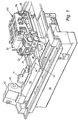
- the grinding machine shown in the drawings is intended to grind axially spaced apart regions of a component such as cam lobes on camshafts or crankpins of crankshafts for engines. It will be described in relation to the grinding of pins along a crankshaft.
- the bed of the machine is denoted by reference numeral 10, the headstock assembly as 12 and the tailstock 14.
- the worktable 16 includes a slideway 18 along which the headstock 14 can move and be positioned and fixed therealong.
- a rotational drive (not shown) is contained within the housing of the headstock assembly 12 and a drive transmitting and crankshaft mounting device 20 extends from the headstock assembly 12 to both support and rotate the crankshaft.
- a further crankshaft supporting device (not shown) extends towards the headstock from the tailstock 14.
- Two grinding wheels 22 and 24 are carried at the outboard ends of two spindle, neither of which is visible but which extend within a casting 26 from the left hand to the right hand thereof.
- the spindles are attached to the two electric motors at 28 and 30 respectively, and the latter rotate the central shafts of the spindles and thereby transmit drive to the wheels 22 and 24 mounted thereon, at the other ends of the spindles.
- the width of the casting 26 and therefore the length of the spindles is such that the motors 28 and 30 are located well to the right of the region containing the workpiece (not shown) and tailstock 14, so that as the wheelhead and wheels 22 and 24 are advanced to engage crankpins along the length of the crankshaft, so the motors do not interfere with the tailstock.
- the casting 26 is an integral part of (or is attached to the forward end of) a larger casting 32 which is pivotally attached by means of a main bearing assembly hidden from view, but one end of which can be seen at 34, so that the casting 32 can pivot up and down relative to the axis of the main bearing 34. It can therefore also pivot relative to a platform 36 which forms the base of the wheelhead assembly and which is slidable orthogonally relative to the workpiece axis along a slideway, the front end of which is visible at 38.
- This slideway comprises the stationary part of a linear motor (not shown) which preferably includes hydrostatic bearings to enable the massive assembly, generally designated 40 to slide freely and with minimal friction and maximum stiffness therealong.
- the slideway 38 is fixed to the main machine frame 10, as is the slideway 42 which extends at right angles thereto, and along which the worktable 16 can slide.
- Drive means is provided for moving the worktable relative to the slide 42 (but this is not visible in the drawings).
- the grinding wheels are CBN wheels. 100mm and 80, diameter wheels have been used. Smaller wheels such as 50mm wheels could also be used.
- coolant can be directed onto the grinding region between each wheel and a crankpin, by means of pipework 44 and 46 respectively which extend from a manifold (not shown) supplied with coolant fluid via a pipe 48 from a pump (not shown).
- Valves are provided within the manifold (not shown) to direct the coolant fluid either via pipe 44 to coolant outlet 50 or via pipe 46 to coolant outlet 52.
- the coolant outlet is selected depending on which wheel is being used at the time.
- valve means or the coolant supply pump or both are controlled so as to enable a trickle flow from whichever outlet 50 or 52 is supplying coolant to the wheel performing a final grinding step.
- a workpiece gauge can be mounted either on the tailstock or on the slideway 18 between the headstock and tailstock or can be carried by the wheelhead assembly (generally designated 40) so that at a point in the grinding process when the pin can be expected to be for example 100 m size, the pin can be gauged.
- adjustments can be made to the control signals to the linear motor controlling the wheelfeed and/or to the headstock drive motor so as to adjust the depth of cut performed during a final single revolution of the pin so as to remove just the right amount of material to leave the pin at the desired finished size, after the said final single revolution.
- a computer (not shown) is associated with the machine shown in Figures 1 and 2, and the signals from a gauge (not shown), from a tacho (not shown) associated with the headstock drive, from position sensors associated with the linear motions of the wheelhead assembly and of the worktable, enables the computer to generate the required control signals for controlling the feed rate, rotational speed of the workpiece and position of the worktable and if desired, the rotational speed of the grinding wheels, for the purposes herein described.
Landscapes
- Engineering & Computer Science (AREA)
- Mechanical Engineering (AREA)
- Grinding Of Cylindrical And Plane Surfaces (AREA)
- Grinding And Polishing Of Tertiary Curved Surfaces And Surfaces With Complex Shapes (AREA)
- Constituent Portions Of Griding Lathes, Driving, Sensing And Control (AREA)
Claims (26)
- Machine à meuler comprenant un châssis principal (10), un support de roues de meulage (40) et une table porte-pièce (16), définissant un axe de pièce, dans laquelle le support de roues coulisse par rapport au châssis principal perpendiculairement à l'axe de la pièce, et la table porte-pièce coulisse par rapport au châssis principal perpendiculairement à la direction de déplacement du support de roues, et un ordinateur recevant des données indiquant au moins un paramètre opérationnel du procédé de meulage, dans laquelle le mécanisme d'entraínement du support de roues est commandé par des signaux générés par l'ordinateur, et comprenant en outre un châssis (32) monté de façon rotative sur le support de roues, deux roues de meulage à entraínement indépendant (22, 24) sont montées sur le châssis de telle manière que le pivotement du châssis entraíne l'alignement de l'axe de l'une ou de l'autre des deux roues de meulage sur l'axe de la pièce, la table porte-pièce comprend une poupée fixe (12) comprenant un mécanisme d'entraínement de pièce permettant de faire tourner une pièce pendant le meulage, et le pivotement du châssis et la vitesse de rotation du mécanisme d'entraínement de la pièce sont également commandées par des signaux générés par l'ordinateur, caractérisée en ce que le châssis est monté de façon articulée sur le support de roues parallèlement à l'axe de pièce et en ce que les deux roues de meulage de petit diamètre sont montées sur le châssis à distance du montage articulé.
- Machine selon la revendication 1, dans laquelle chaque roue de meulage est montée au niveau d'une extrémité d'une broche ayant un arbre central directement entraíné par un moteur.
- Machine selon la revendication 2, dans laquelle l'arbre est supporté par des moyens de palier hydrostatique.
- Machine selon l'une des revendications 2 ou 3, dans laquelle la table porte-pièce supporte un système de contre-poupée (14) et la longueur de chaque broche est définie de manière à positionner chacun des moteurs axialement dégagé du système de contre-poupée lorsque les roues sont alignées pour venir en contact de zones d'une pièce les plus proches de la poupée fixe.
- Machine selon l'une quelconque des revendications 1 à 4, dans laquelle l'une des roues est utilisée pour un meulage grossier et l'autre pour un meulage de finition d'une pièce, et les roues sont choisies en fonction du type de meulage.
- Machine selon la revendication 5, dans laquelle la roue de meulage supérieure est agencée de façon à réaliser un meulage grossier et la roue inférieure est agencée de façon à effectuer un meulage de finition d'une pièce, de telle manière que le meulage grossier soit réalisé avec le châssis dans sa position abaissée.
- Machine selon l'une quelconque des revendications 1 à 4, dans laquelle les roues sont similaires et elles réalisent toutes les deux la même fonction de meulage, et une roue puis l'autre sont utilisées tour à tour de telle manière que l'usure des roues soit répartie de façon uniforme entre les deux roues et que le meulage ne soit interrompu que pour décrasser ou remplacer des roues usées, après que les deux roues aient atteint un niveau d'usure inacceptable.
- Machine selon l'une quelconque des revendications 1 à 7, dans laquelle l'axe de l'une ou l'autre des deux roues de meulage est aligné sur l'axe de la pièce en élevant ou abaissant le châssis (32) par rapport à une plate-forme (36) faisant partie du support de roues (40).
- Machine selon la revendication 8, dans laquelle la rotation du châssis est réalisée en utilisant un mécanisme d'entraínement pneumatique, hydraulique ou électrique.
- Machine selon l'une quelconque des revendications 1 à 9, dans laquelle le mécanisme d'entraínement du support de roues est un mécanisme d'entraínement linéaire électromagnétique.
- Machine selon la revendication 10, dans laquelle des paliers hydrostatiques sont prévus pour soutenir le support de roues sur une glissière, laquelle comprend elle-même une partie de l'entraínement linéaire.
- Machine selon l'une quelconque des revendications 1 à 11, permettant de meuler des composants cylindriques, et comprenant en outre des moyens de calibrage montés sur la machine de meulage afin de permettre la réalisation d'un calibrage sans démonter de pièce.
- Machine selon l'une quelconque des revendications 1 à 12, dans laquelle une alimentation en liquide de refroidissement est prévue avec des moyens pour fournir de façon sélective un liquide de refroidissement vers l'une ou l'autre des deux roues de meulage en fonction de la roue utilisée pour meuler au moment donné.
- Machine selon la revendication 13, dans laquelle le débit du liquide de refroidissement peut être réglé.
- Procédé de meulage de pièces cylindriques telles que des manetons de vilebrequins utilisant une machine à meuler telle que revendiquée dans l'une quelconque des revendications 1 à 14, dans lequel pendant le meulage de chaque pièce :(i) la force de découpe est maintenue sur le support de roues afin de maintenir la roue et la pièce soumises à une charge modérée constante même pendant ce qui aurait été l'étape de léchage des procédés connus ; et(ii) la vitesse de rotation du mécanisme d'entraínement de la pièce est réduite ; afin d'empêcher l'apparition de marques en ricochet et de broutage sur la surface de la pièce.
- Procédé selon la revendication 15, dans lequel la vitesse de rotation réduite du mécanisme d'entraínement de la pièce se situe dans une fourchette comprise entre 1 et 5 tours-minute.
- Procédé selon la revendication 15 ou 16, dans lequel l'entraínement de la roue, pendant la vitesse réduite de la rotation de la pièce, est ajusté de manière à retirer une profondeur de matériau suffisante pendant une seule rotation du vilebrequin afin d'amener la pièce à sa taille finale.
- Procédé selon la revendication 17, dans lequel la pièce est un maneton d'un vilebrequin et le maneton est calibré avant que l'étape de meulage consistant en une dernière révolution simple soit réalisée, de manière à déterminer la profondeur de coupe nécessaire pour obtenir la taille finale et l'entraínement des roues est commandé de manière à retirer la profondeur nécessaire pour obtenir la taille finale.
- Procédé selon l'une quelconque des revendications 15 à 18, dans lequel la pression de l'alimentation en liquide de refroidissement est réduite pendant la dernière révolution simple du vilebrequin, de manière à ce que le débit de liquide de refroidissement soit considérablement réduit pendant la dernière révolution.
- Procédé selon la revendication 15, dans lequel la majorité du métal, devant être retiré pour meuler un maneton en acier à la taille souhaitée avec une roue CBN, est retirée d'une manière connue et au fur et à mesure que le maneton approche de la taille finale et qu'il ne reste plus qu'approximativement 50 µm à enlever sur le rayon, le maneton est calibré et la dimension supérieure précise est déterminée, la vitesse de la pièce diminue pour atteindre une vitesse située dans une fourchette de 1 à 5 tours-minute, généralement 3 tours-minute, le débit de liquide de refroidissement est réduit et l'entraínement de la roue est contrôlé de manière à manière à enlever, au cours d'une seule révolution du vilebrequin, un dernier niveau de profondeur du maneton, dont la taille est déterminée par le calibrage après lequel la poupée porte-meule se rétracte afin que la roue se dégage complètement du maneton, sans étape de léchage laissant ainsi le maneton meulé à la taille souhaitée.
- Procédé selon l'une quelconque des revendications 15 à 20, dans lequel l'utilisation d'une roue CBN pour meuler des manetons d'un vilebrequin s'accompagne de variations à intervalles de la vitesse de rotation de la roue pendant le meulage des manetons.
- Procédé selon la revendication 21, dans lequel la vitesse de la roue est modifiée après que chaque nième maneton a été meulé.
- Procédé selon la revendication 22, dans lequel n est équivalent à 3 mais peut représenter toute valeur à partir de 1.
- Procédé selon l'une quelconque des revendications 21 à 23, dans lequel la modification de la vitesse de rotation est de l'ordre de ± 2-5% de la vitesse nominale de la roue.
- Machine à meuler selon l'une quelconque des revendications 1 à 14, dans laquelle les deux roues de meulage présentent le même diamètre nominal.
- Procédé de meulage de pièces cylindriques selon l'une quelconque des revendications 15 à 25, dans lequel les deux roues de meulage présentent le même diamètre nominal.
Applications Claiming Priority (5)
| Application Number | Priority Date | Filing Date | Title |
|---|---|---|---|
| GBGB9925367.6A GB9925367D0 (en) | 1999-10-27 | 1999-10-27 | Improved grinding method |
| GB9925367 | 1999-10-27 | ||
| GBGB9925487.2A GB9925487D0 (en) | 1999-10-28 | 1999-10-28 | Crankpin grinding methods |
| GB9925487 | 1999-10-28 | ||
| PCT/GB2000/004130 WO2001030537A1 (fr) | 1999-10-27 | 2000-10-26 | Machine a meuler dotee de deux roues de meulage |
Publications (2)
| Publication Number | Publication Date |
|---|---|
| EP1224059A1 EP1224059A1 (fr) | 2002-07-24 |
| EP1224059B1 true EP1224059B1 (fr) | 2003-05-02 |
Family
ID=26316026
Family Applications (5)
| Application Number | Title | Priority Date | Filing Date |
|---|---|---|---|
| EP00971591A Expired - Lifetime EP1224057B1 (fr) | 1999-10-27 | 2000-10-26 | Procede de rectification de maneton |
| EP04013436A Expired - Lifetime EP1473113B1 (fr) | 1999-10-27 | 2000-10-26 | Procédé de meulage d'un pièce permettant de réaliser une vitesse constante d'enlèvement de copeaux |
| EP00969713A Expired - Lifetime EP1224056B1 (fr) | 1999-10-27 | 2000-10-26 | Procede de meulage de piece permettant de parvenir a une vitesse d'elimination constante de la poupee |
| EP00969715A Expired - Lifetime EP1224059B1 (fr) | 1999-10-27 | 2000-10-26 | Machine a meuler dotee de deux roues de meulage |
| EP00971592A Expired - Lifetime EP1224058B1 (fr) | 1999-10-27 | 2000-10-26 | Procede de meulage a puissance constante sur la broche |
Family Applications Before (3)
| Application Number | Title | Priority Date | Filing Date |
|---|---|---|---|
| EP00971591A Expired - Lifetime EP1224057B1 (fr) | 1999-10-27 | 2000-10-26 | Procede de rectification de maneton |
| EP04013436A Expired - Lifetime EP1473113B1 (fr) | 1999-10-27 | 2000-10-26 | Procédé de meulage d'un pièce permettant de réaliser une vitesse constante d'enlèvement de copeaux |
| EP00969713A Expired - Lifetime EP1224056B1 (fr) | 1999-10-27 | 2000-10-26 | Procede de meulage de piece permettant de parvenir a une vitesse d'elimination constante de la poupee |
Family Applications After (1)
| Application Number | Title | Priority Date | Filing Date |
|---|---|---|---|
| EP00971592A Expired - Lifetime EP1224058B1 (fr) | 1999-10-27 | 2000-10-26 | Procede de meulage a puissance constante sur la broche |
Country Status (8)
| Country | Link |
|---|---|
| US (6) | US6767273B1 (fr) |
| EP (5) | EP1224057B1 (fr) |
| CA (4) | CA2383908A1 (fr) |
| DE (5) | DE60007542T2 (fr) |
| ES (5) | ES2214328T3 (fr) |
| GB (4) | GB2357722B (fr) |
| MX (3) | MXPA02004139A (fr) |
| WO (4) | WO2001030534A2 (fr) |
Families Citing this family (34)
| Publication number | Priority date | Publication date | Assignee | Title |
|---|---|---|---|---|
| GB2357722B (en) * | 1999-10-27 | 2003-05-07 | Unova Uk Ltd | Workpiece grinding method which achieves a constant stock removal rate |
| US20040176017A1 (en) * | 2003-02-25 | 2004-09-09 | Aleksander Zelenski | Apparatus and methods for abrading a work piece |
| TWI388397B (zh) * | 2004-02-25 | 2013-03-11 | Studer Ag Fritz | 用於工作件加工的加工機 |
| GB0410944D0 (en) * | 2004-05-15 | 2004-06-16 | Unova Uk Ltd | Improvements in and relating to the grinding of cylindrical surfaces and adjoining side-walls |
| ITUD20040101A1 (it) * | 2004-05-17 | 2004-08-17 | Delle Vedove Levigatrici Spa | Macchina per rifinire un oggetto quale un profilato, un pannello, o simile |
| JP4730944B2 (ja) * | 2004-06-04 | 2011-07-20 | コマツNtc株式会社 | 多頭研削盤及び多頭研削盤を用いた研削方法 |
| JP2006159314A (ja) * | 2004-12-03 | 2006-06-22 | Toyoda Mach Works Ltd | クランクピンの研削方法及び研削盤 |
| US20060205321A1 (en) * | 2005-03-11 | 2006-09-14 | United Technologies Corporation | Super-abrasive machining tool and method of use |
| JP4940729B2 (ja) * | 2006-03-31 | 2012-05-30 | 株式会社ジェイテクト | 工作物の研削方法及び研削装置 |
| DE102007030958B4 (de) * | 2007-07-04 | 2014-09-11 | Siltronic Ag | Verfahren zum Schleifen von Halbleiterscheiben |
| US8277279B2 (en) * | 2007-12-14 | 2012-10-02 | Rolls-Royce Corporation | Method for processing a work-piece |
| DE202009014739U1 (de) * | 2009-10-20 | 2011-03-10 | Schaudt Mikrosa Gmbh | Schleifmaschine mit zwei Spindelsätzen |
| CN102905847B (zh) * | 2010-06-04 | 2016-06-01 | 格里森工场 | 加工工艺的自适应控制 |
| US8568198B2 (en) | 2010-07-16 | 2013-10-29 | Pratt & Whitney Canada Corp. | Active coolant flow control for machining processes |
| CN102452030B (zh) * | 2010-10-27 | 2016-07-06 | 株式会社捷太格特 | 磨削方法、磨削系统以及多功能磨削机床 |
| CN102218689B (zh) * | 2011-06-07 | 2013-03-27 | 苏州领航自动化科技有限公司 | 刨槽机 |
| CN103286662B (zh) * | 2013-06-18 | 2015-09-30 | 苏州新达电扶梯部件有限公司 | 一种车床机头打磨装置 |
| JP6040947B2 (ja) * | 2014-02-20 | 2016-12-07 | 信越半導体株式会社 | ワークの両頭研削方法 |
| CN103949947B (zh) * | 2014-05-14 | 2016-11-02 | 无锡上机数控股份有限公司 | 大型数控曲轴主轴颈外圆磨床 |
| SE538599C2 (sv) | 2014-05-23 | 2016-09-27 | Scania Cv Ab | Förfarande för slipning av ett arbetsstycke och förfarande för bestämning av processparametrar |
| GB201500259D0 (en) * | 2015-01-08 | 2015-02-25 | Fives Landis Ltd | Improvements to machining process control |
| JP6676938B2 (ja) * | 2015-11-20 | 2020-04-08 | 株式会社ジェイテクト | カム研削装置、およびカム研削方法 |
| JP2017116297A (ja) * | 2015-12-21 | 2017-06-29 | 株式会社ミツトヨ | 画像測定方法及び画像測定機 |
| CN106808349B (zh) * | 2016-07-19 | 2018-12-11 | 东莞理工学院 | 一种电机轴全自动抛光机 |
| CN107649992A (zh) * | 2017-09-21 | 2018-02-02 | 镇江颀龙科技有限公司 | 一种打磨装置 |
| US10639763B2 (en) * | 2017-11-14 | 2020-05-05 | Ford Motor Company | Method for journal finishing of crankshafts, camshafts, and journals |
| GB2569307B (en) * | 2017-12-12 | 2022-06-29 | Fives Landis Ltd | Machine tools and methods of operation thereof |
| CN110125776A (zh) * | 2019-06-17 | 2019-08-16 | 昆明理工大学 | 一种多面打磨机 |
| CN111546147A (zh) * | 2019-07-30 | 2020-08-18 | 徐建方 | 水晶玻璃棒磨削机及其限位装置 |
| CN111546139B (zh) * | 2020-05-15 | 2021-12-07 | 重庆南雁实业集团龙剑机械制造有限公司 | 一种阶梯轴成型加工设备及加工方法 |
| CN111702562B (zh) * | 2020-06-23 | 2021-10-08 | 杭州萧山中亚汽配有限公司 | 一种齿环等速万向节的自动化加工系统及其加工方法 |
| CN112496961B (zh) * | 2020-11-26 | 2021-12-07 | 乐清市虹桥职业技术学校 | 一种数控车床配件的自动生产装置 |
| CN112816356A (zh) * | 2021-01-18 | 2021-05-18 | 中铁隆昌铁路器材有限公司 | 一种快速打磨砂轮磨削性能试验装置 |
| CN113427370A (zh) * | 2021-06-11 | 2021-09-24 | 深圳市友创智能设备有限公司 | 一种双砂轮定位方法 |
Family Cites Families (65)
| Publication number | Priority date | Publication date | Assignee | Title |
|---|---|---|---|---|
| US2209538A (en) * | 1937-07-30 | 1940-07-30 | Porsche Kg | Means and method for producing cams |
| US2898707A (en) * | 1956-05-02 | 1959-08-11 | Reishauer Werkzeuge A G | Machine for the grinding of spur gears and helical gears by the generating principle |
| US3798846A (en) * | 1969-05-23 | 1974-03-26 | R Smith | Method of grinding |
| US3653855A (en) * | 1969-05-23 | 1972-04-04 | Smith Roderick | Grinding system |
| US3908315A (en) * | 1973-10-19 | 1975-09-30 | Sundstrand Syracuse | Grinding machine systems |
| GB1559674A (en) * | 1975-08-08 | 1980-01-23 | Ward M M | Grinding machines |
| US4118900A (en) * | 1976-03-29 | 1978-10-10 | Seiko Seiki Kabushiki Kaisha | Method for controlling grinding process |
| JPS52155493A (en) * | 1976-06-18 | 1977-12-23 | Toyoda Mach Works Ltd | Process for grinding cam |
| US4187646A (en) * | 1976-08-16 | 1980-02-12 | The Valeron Corporation | Apparatus for grinding |
| US4139969A (en) * | 1977-05-06 | 1979-02-20 | Brown Bernard J | Apparatus for controlling the grinding of workpieces |
| GB1596635A (en) * | 1977-07-26 | 1981-08-26 | Newall Eng | Cam machining |
| DE2822346C2 (de) * | 1978-05-22 | 1985-09-05 | GFM Gesellschaft für Fertigungstechnik und Maschinenbau GmbH, Steyr | Elektrische numerische Programmsteuerung für Kurbelwellenfräsmaschinen und Kurbelwellen-Schleifmaschinen |
| SU880244A3 (ru) * | 1978-08-18 | 1981-11-07 | Мааг-Цанрэдер Унд-Машинен Аг (Фирма) | Способ шлифовани зубчатых колес и станок дл его осуществлени |
| FR2460182A1 (fr) * | 1979-06-29 | 1981-01-23 | Gendron Sa | Dispositif permettant d'usiner des cames avec precision, et avec une vitesse de coupe constante |
| JPS56114660A (en) * | 1980-02-12 | 1981-09-09 | Toyoda Mach Works Ltd | Numerical controller which controls cam machining |
| JPS5748468A (en) * | 1980-09-02 | 1982-03-19 | Toyoda Mach Works Ltd | Cam grinding method |
| US4443975A (en) | 1981-01-26 | 1984-04-24 | The Warner & Swasey Company | Dual wheel cylindrical grinding center |
| US4443976A (en) * | 1982-01-29 | 1984-04-24 | Litton Industrial Products, Inc. | Cylindrical grinding machine |
| JPS58192743A (ja) * | 1982-04-29 | 1983-11-10 | Toyoda Mach Works Ltd | カム研削方法 |
| GB2125716B (en) * | 1982-07-23 | 1985-11-20 | Honda Motor Co Ltd | Cam grinding |
| US4590573A (en) * | 1982-09-17 | 1986-05-20 | Robert Hahn | Computer-controlled grinding machine |
| JPS59191246U (ja) * | 1983-06-02 | 1984-12-19 | 三興機械株式会社 | 研削機 |
| JPS6056821A (ja) * | 1983-09-09 | 1985-04-02 | Honda Motor Co Ltd | 歯車研削機 |
| JPS6090667A (ja) * | 1983-10-20 | 1985-05-21 | Toyoda Mach Works Ltd | カム研削方法 |
| DE3523013A1 (de) | 1985-06-27 | 1987-01-02 | Schaudt Maschinenbau Gmbh | Schleifmaschine |
| DE3529099A1 (de) * | 1985-08-14 | 1987-02-19 | Fortuna Werke Maschf Ag | Verfahren und vorrichtung zum spanabhebenden bearbeiten einer oberflaeche von profilen mit einer von einer kreisform abweichenden kontur, insbesondere nockenwellen |
| JPH0716874B2 (ja) * | 1986-02-19 | 1995-03-01 | 三菱重工業株式会社 | ロ−ル研削制御方法及びその装置 |
| JPS6384845A (ja) * | 1986-09-24 | 1988-04-15 | Toyoda Mach Works Ltd | 非真円形工作物の加工方法 |
| DE3702594C3 (de) * | 1987-01-29 | 1995-04-06 | Fortuna Werke Maschf Ag | Verfahren und Vorrichtung zum Schleifen von Nocken an Nockenwellen |
| US4790698A (en) * | 1987-05-13 | 1988-12-13 | Cm Systems, Incorporated | Monotonic cutting machine |
| JP2516382B2 (ja) * | 1987-11-06 | 1996-07-24 | セイコー精機株式会社 | 磁気軸受を主軸にもつ加工装置 |
| DE3737641A1 (de) * | 1987-10-19 | 1989-04-27 | Fortuna Werke Maschf Ag | Verfahren zum aussenrundschleifen von werkstuecken |
| DE3814124A1 (de) * | 1988-04-27 | 1989-11-09 | Fortuna Werke Maschf Ag | Verfahren zum schleifen von nocken einer nockenscheibe |
| EP0342528A3 (fr) * | 1988-05-19 | 1991-04-17 | Fortuna-Werke Maschinenfabrik GmbH | Méthode de rectification de cames d'arbre à cames |
| DE4023587C2 (de) * | 1990-07-25 | 1993-11-18 | Fortuna Werke Maschf Ag | Verfahren zum meßgesteuerten Umfangsschleifen von radial unrunden Werkstücken |
| DE4030375A1 (de) * | 1990-09-26 | 1992-04-09 | Thielenhaus Ernst Kg | Verfahren und vorrichtung zum feinschleifen der exzentrischen nockenoberflaeche an den nocken einer nockenwelle |
| JPH04171109A (ja) * | 1990-11-02 | 1992-06-18 | Komatsu Ltd | カムシャフトの等負荷切削方法 |
| DE4103090C1 (fr) * | 1991-02-01 | 1992-08-27 | Erwin 7618 Nordrach De Junker | |
| DE4137924C2 (de) * | 1991-11-18 | 1997-12-04 | Schaudt Maschinenbau Gmbh | Verfahren und Vorrichtung zum numerisch gesteuerten Schleifen von Nocken einer Nockenwelle |
| JP2930462B2 (ja) * | 1991-12-26 | 1999-08-03 | 豊田工機株式会社 | 研削方法 |
| DE4202513C2 (de) * | 1992-01-30 | 1997-01-23 | Naxos Union Schleifmittel | Verfahren zum Schleifen von Hublagerzapfen einer Kurbelwelle und Schleifmaschine zur Durchführung des Verfahrens |
| DE4210710C2 (de) * | 1992-03-27 | 2003-03-20 | Niles Werkzeugmaschinen Gmbh | Verfahren und Einrichtung zum Schleifen rillenförmiger Außenprofile eines Werkstückes |
| GB2268895B (en) * | 1992-07-18 | 1995-06-28 | Litton Uk Ltd | Grinding method and apparatus |
| DE4235408A1 (de) | 1992-10-21 | 1994-04-28 | Schaudt Maschinenbau Gmbh | Verfahren und Vorrichtung zum Schleifen von unrunden Werkstücken |
| US5484327A (en) * | 1993-06-21 | 1996-01-16 | Eaton Corporation | Method and apparatus for simultaneously grinding a workpiece with first and second grinding wheels |
| GB9401462D0 (en) * | 1994-01-26 | 1994-03-23 | Western Atlas Uk Ltd | Improvements in and relating to grinding |
| JPH07256556A (ja) * | 1994-03-23 | 1995-10-09 | Amada Washino Co Ltd | 平面研削盤の主軸モータの回転数制御による研削加工方法 |
| DE4426452C1 (de) * | 1994-07-26 | 1995-09-07 | Erwin Junker | Verfahren und Maschine zum Schleifen von Nocken mit konkaven Flanken |
| JP3490534B2 (ja) * | 1995-03-23 | 2004-01-26 | オークマ株式会社 | 非円形工作物の研削加工方法及び装置 |
| DE19516711A1 (de) | 1995-05-06 | 1996-11-07 | Schaudt Maschinenbau Gmbh | Werkzeugmaschine mit zwei Arbeitsspindeln |
| US5613899A (en) * | 1995-06-05 | 1997-03-25 | Southern Carbide Specialists, Inc. | Centerless ceramic ferrule grinder |
| DE19620813C2 (de) * | 1996-05-23 | 2000-07-20 | Junker Erwin Maschf Gmbh | Verfahren und Vorrichtung zum Unrundschleifen von Nockenformen mit konkaven Flanken |
| US5895311A (en) * | 1996-06-06 | 1999-04-20 | Fuji Xerox Co., Ltd. | Abrasive device that maintains normal line of contact with curved abrasive surface and method of using same |
| CA2259240C (fr) * | 1996-08-01 | 2003-12-30 | Radtec, Inc. | Machine de microfinition |
| US5919081A (en) * | 1996-09-04 | 1999-07-06 | Unova Ip Corporation | Method and apparatus for computer numerically controlled pin grinder gauge |
| DE69704165T2 (de) * | 1996-09-13 | 2001-08-23 | Unova U.K. Ltd., Aylesbury | Verbesserungen in/oder bezüglich werkstückschleifen |
| JPH10138108A (ja) * | 1996-10-31 | 1998-05-26 | Nidek Co Ltd | 眼鏡レンズ研削加工機及び眼鏡レンズ研削加工方法 |
| US6106373A (en) * | 1997-04-02 | 2000-08-22 | Fabris; Mario | Multi-task grinding wheel machine |
| US5975995A (en) * | 1997-06-25 | 1999-11-02 | Unova Ip Corp. | Machining apparatus and method |
| GB9719969D0 (en) * | 1997-09-20 | 1997-11-19 | Western Atlas Uk Ltd | Improved grinding process |
| JP3071165B2 (ja) * | 1997-10-06 | 2000-07-31 | ユニオンツール株式会社 | ドリル先端刃付け装置 |
| DE19756610A1 (de) | 1997-12-18 | 1999-07-01 | Junker Erwin Maschf Gmbh | Verfahren und Vorrichtung zum Schleifen von Werkstücken mit zum Schleifen zeitparaller Feinstbearbeitung |
| US6234881B1 (en) * | 1998-08-06 | 2001-05-22 | Walter Ag | Grinding machine for forming chip-producing cutting tools |
| DE19919893A1 (de) * | 1999-04-30 | 2000-11-09 | Junker Erwin Maschf Gmbh | Vor- und Fertigschleifen einer Kurbelwelle in einer Aufspannung |
| GB2357722B (en) * | 1999-10-27 | 2003-05-07 | Unova Uk Ltd | Workpiece grinding method which achieves a constant stock removal rate |
-
2000
- 2000-10-26 GB GB0026259A patent/GB2357722B/en not_active Expired - Fee Related
- 2000-10-26 CA CA002383908A patent/CA2383908A1/fr not_active Abandoned
- 2000-10-26 US US10/111,640 patent/US6767273B1/en not_active Expired - Fee Related
- 2000-10-26 MX MXPA02004139A patent/MXPA02004139A/es active IP Right Grant
- 2000-10-26 ES ES00971592T patent/ES2214328T3/es not_active Expired - Lifetime
- 2000-10-26 WO PCT/GB2000/004136 patent/WO2001030534A2/fr not_active Ceased
- 2000-10-26 MX MXPA02004136A patent/MXPA02004136A/es active IP Right Grant
- 2000-10-26 CA CA002380560A patent/CA2380560A1/fr not_active Abandoned
- 2000-10-26 ES ES00969715T patent/ES2198356T3/es not_active Expired - Lifetime
- 2000-10-26 US US10/111,642 patent/US6808438B1/en not_active Expired - Fee Related
- 2000-10-26 EP EP00971591A patent/EP1224057B1/fr not_active Expired - Lifetime
- 2000-10-26 EP EP04013436A patent/EP1473113B1/fr not_active Expired - Lifetime
- 2000-10-26 DE DE60007542T patent/DE60007542T2/de not_active Expired - Lifetime
- 2000-10-26 GB GB0026258A patent/GB2357721B/en not_active Expired - Fee Related
- 2000-10-26 CA CA002388426A patent/CA2388426A1/fr not_active Abandoned
- 2000-10-26 DE DE60018778T patent/DE60018778T2/de not_active Expired - Lifetime
- 2000-10-26 GB GB0026257A patent/GB2357720B/en not_active Expired - Fee Related
- 2000-10-26 MX MXPA02004140A patent/MXPA02004140A/es unknown
- 2000-10-26 DE DE60002497T patent/DE60002497T2/de not_active Expired - Lifetime
- 2000-10-26 WO PCT/GB2000/004130 patent/WO2001030537A1/fr not_active Ceased
- 2000-10-26 ES ES00971591T patent/ES2202183T3/es not_active Expired - Lifetime
- 2000-10-26 DE DE60030790T patent/DE60030790T2/de not_active Expired - Lifetime
- 2000-10-26 WO PCT/GB2000/004126 patent/WO2001030535A1/fr not_active Ceased
- 2000-10-26 US US10/111,639 patent/US6682403B1/en not_active Expired - Fee Related
- 2000-10-26 EP EP00969713A patent/EP1224056B1/fr not_active Expired - Lifetime
- 2000-10-26 EP EP00969715A patent/EP1224059B1/fr not_active Expired - Lifetime
- 2000-10-26 DE DE60003835T patent/DE60003835T2/de not_active Expired - Lifetime
- 2000-10-26 ES ES04013436T patent/ES2268543T3/es not_active Expired - Lifetime
- 2000-10-26 US US10/111,641 patent/US6811465B1/en not_active Expired - Fee Related
- 2000-10-26 EP EP00971592A patent/EP1224058B1/fr not_active Expired - Lifetime
- 2000-10-26 ES ES00969713T patent/ES2239620T3/es not_active Expired - Lifetime
- 2000-10-26 WO PCT/GB2000/004135 patent/WO2001030536A1/fr not_active Ceased
- 2000-10-26 CA CA002384988A patent/CA2384988A1/fr not_active Abandoned
- 2000-10-26 GB GB0026256A patent/GB2357719B/en not_active Expired - Fee Related
-
2004
- 2004-09-08 US US10/936,167 patent/US7297046B2/en not_active Expired - Fee Related
- 2004-09-08 US US10/936,291 patent/US7153194B2/en not_active Expired - Fee Related
Also Published As
Similar Documents
| Publication | Publication Date | Title |
|---|---|---|
| US6682403B1 (en) | Grinding machine with two grinding wheels | |
| EP1180414B1 (fr) | Machine à meuler | |
| CN100333876C (zh) | 磨削一种旋转对称的机器部件的方法和装置 | |
| CN101687301B (zh) | 通过外圆研磨来研磨曲轴的主轴承和连杆轴承的方法以及实施该方法的装置 | |
| US5899797A (en) | Method and apparatus for grinding cams with concave sides | |
| CZ296364B6 (cs) | Zpusob bezhrotového brousení válcových ploch a zarízení k jeho provádení | |
| GB2272852A (en) | Method of and machine for grinding cams | |
| CA2261063C (fr) | Ameliorations portant sur des procedes et appareils de meulage | |
| GB2351929A (en) | Improvements relating to grinding methods and apparatus | |
| SU1764967A1 (ru) | Станок дл обработки наружных цилиндрических поверхностей деталей | |
| MXPA02003362A (es) | Metodo de desbaste con potencia constante en el husillo. |
Legal Events
| Date | Code | Title | Description |
|---|---|---|---|
| PUAI | Public reference made under article 153(3) epc to a published international application that has entered the european phase |
Free format text: ORIGINAL CODE: 0009012 |
|
| 17P | Request for examination filed |
Effective date: 20011130 |
|
| AK | Designated contracting states |
Kind code of ref document: A1 Designated state(s): AT BE CH CY DE DK ES FI FR GB GR IE IT LI LU MC NL PT SE |
|
| AX | Request for extension of the european patent |
Free format text: AL;LT;LV;MK;RO;SI |
|
| GRAH | Despatch of communication of intention to grant a patent |
Free format text: ORIGINAL CODE: EPIDOS IGRA |
|
| GRAH | Despatch of communication of intention to grant a patent |
Free format text: ORIGINAL CODE: EPIDOS IGRA |
|
| GRAA | (expected) grant |
Free format text: ORIGINAL CODE: 0009210 |
|
| AK | Designated contracting states |
Designated state(s): DE ES FR IT |
|
| REF | Corresponds to: |
Ref document number: 60002497 Country of ref document: DE Date of ref document: 20030605 Kind code of ref document: P |
|
| REG | Reference to a national code |
Ref country code: IE Ref legal event code: FG4D |
|
| LTIE | Lt: invalidation of european patent or patent extension |
Effective date: 20030502 |
|
| ET | Fr: translation filed | ||
| REG | Reference to a national code |
Ref country code: ES Ref legal event code: FG2A Ref document number: 2198356 Country of ref document: ES Kind code of ref document: T3 |
|
| PLBE | No opposition filed within time limit |
Free format text: ORIGINAL CODE: 0009261 |
|
| STAA | Information on the status of an ep patent application or granted ep patent |
Free format text: STATUS: NO OPPOSITION FILED WITHIN TIME LIMIT |
|
| 26N | No opposition filed |
Effective date: 20040203 |
|
| REG | Reference to a national code |
Ref country code: IE Ref legal event code: MM4A |
|
| REG | Reference to a national code |
Ref country code: FR Ref legal event code: TP |
|
| REG | Reference to a national code |
Ref country code: FR Ref legal event code: CD |
|
| REG | Reference to a national code |
Ref country code: DE Ref legal event code: R082 Ref document number: 60002497 Country of ref document: DE Representative=s name: LOESENBECK UND KOLLEGEN, DE |
|
| REG | Reference to a national code |
Ref country code: FR Ref legal event code: CD Owner name: FIVES LANDIS LIMITED, GB Effective date: 20141203 Ref country code: ES Ref legal event code: PC2A Owner name: FIVE LANDIS LIMITED Effective date: 20141223 |
|
| REG | Reference to a national code |
Ref country code: DE Ref legal event code: R081 Ref document number: 60002497 Country of ref document: DE Owner name: FIVES LANDIS LIMITED, GB Free format text: FORMER OWNER: CINETIC LANDIS LTD., KEIGHLEY, GB Effective date: 20141211 Ref country code: DE Ref legal event code: R082 Ref document number: 60002497 Country of ref document: DE Representative=s name: LOESENBECK UND KOLLEGEN, DE Effective date: 20141211 |
|
| REG | Reference to a national code |
Ref country code: FR Ref legal event code: PLFP Year of fee payment: 16 |
|
| REG | Reference to a national code |
Ref country code: FR Ref legal event code: PLFP Year of fee payment: 17 |
|
| PGFP | Annual fee paid to national office [announced via postgrant information from national office to epo] |
Ref country code: DE Payment date: 20161020 Year of fee payment: 17 Ref country code: FR Payment date: 20161020 Year of fee payment: 17 |
|
| PGFP | Annual fee paid to national office [announced via postgrant information from national office to epo] |
Ref country code: ES Payment date: 20161011 Year of fee payment: 17 Ref country code: IT Payment date: 20161024 Year of fee payment: 17 |
|
| REG | Reference to a national code |
Ref country code: DE Ref legal event code: R119 Ref document number: 60002497 Country of ref document: DE |
|
| REG | Reference to a national code |
Ref country code: FR Ref legal event code: ST Effective date: 20180629 |
|
| PG25 | Lapsed in a contracting state [announced via postgrant information from national office to epo] |
Ref country code: DE Free format text: LAPSE BECAUSE OF NON-PAYMENT OF DUE FEES Effective date: 20180501 |
|
| PG25 | Lapsed in a contracting state [announced via postgrant information from national office to epo] |
Ref country code: FR Free format text: LAPSE BECAUSE OF NON-PAYMENT OF DUE FEES Effective date: 20171031 |
|
| PG25 | Lapsed in a contracting state [announced via postgrant information from national office to epo] |
Ref country code: IT Free format text: LAPSE BECAUSE OF NON-PAYMENT OF DUE FEES Effective date: 20171026 |
|
| REG | Reference to a national code |
Ref country code: ES Ref legal event code: FD2A Effective date: 20181221 |
|
| PG25 | Lapsed in a contracting state [announced via postgrant information from national office to epo] |
Ref country code: ES Free format text: LAPSE BECAUSE OF NON-PAYMENT OF DUE FEES Effective date: 20171027 |