EP1235246A2 - Halter für einen Sicherungseinsatz - Google Patents
Halter für einen Sicherungseinsatz Download PDFInfo
- Publication number
- EP1235246A2 EP1235246A2 EP02003841A EP02003841A EP1235246A2 EP 1235246 A2 EP1235246 A2 EP 1235246A2 EP 02003841 A EP02003841 A EP 02003841A EP 02003841 A EP02003841 A EP 02003841A EP 1235246 A2 EP1235246 A2 EP 1235246A2
- Authority
- EP
- European Patent Office
- Prior art keywords
- fuse
- holder
- holder housing
- recited
- fuse holder
- Prior art date
- Legal status (The legal status is an assumption and is not a legal conclusion. Google has not performed a legal analysis and makes no representation as to the accuracy of the status listed.)
- Granted
Links
Images


Classifications
-
- H—ELECTRICITY
- H01—ELECTRIC ELEMENTS
- H01H—ELECTRIC SWITCHES; RELAYS; SELECTORS; EMERGENCY PROTECTIVE DEVICES
- H01H85/00—Protective devices in which the current flows through a part of fusible material and this current is interrupted by displacement of the fusible material when this current becomes excessive
- H01H85/02—Details
- H01H85/20—Bases for supporting the fuse; Separate parts thereof
- H01H85/203—Bases for supporting the fuse; Separate parts thereof for fuses with blade type terminals
- H01H85/2035—Bases for supporting the fuse; Separate parts thereof for fuses with blade type terminals for miniature fuses with parallel side contacts
-
- H—ELECTRICITY
- H01—ELECTRIC ELEMENTS
- H01H—ELECTRIC SWITCHES; RELAYS; SELECTORS; EMERGENCY PROTECTIVE DEVICES
- H01H85/00—Protective devices in which the current flows through a part of fusible material and this current is interrupted by displacement of the fusible material when this current becomes excessive
- H01H85/02—Details
- H01H85/20—Bases for supporting the fuse; Separate parts thereof
- H01H2085/2085—Holders for mounting a fuse on a printed circuit
-
- H—ELECTRICITY
- H01—ELECTRIC ELEMENTS
- H01H—ELECTRIC SWITCHES; RELAYS; SELECTORS; EMERGENCY PROTECTIVE DEVICES
- H01H85/00—Protective devices in which the current flows through a part of fusible material and this current is interrupted by displacement of the fusible material when this current becomes excessive
- H01H85/02—Details
- H01H85/20—Bases for supporting the fuse; Separate parts thereof
- H01H2085/209—Modular assembly of fuses or holders, e.g. side by side; combination of a plurality of identical fuse units
Definitions
- the present invention belongs to a field of fuse holder, into which a blade type fuse, with blade terminals protruding from its body, is fitted.
- a fuse fitting device into which a blade type fuse is fitted, is known.
- This device comprises a block of synthetic resin, and connecting terminals, which are inserted from below into a chamber in the block and fitted to a lance of the block.
- electric wires are connected to the connecting terminals, these connecting terminals are inserted into the chamber of the block and fitted to the lance, a fuse is inserted from above into the chamber of the block, and the blade terminals of the fuse are fitted into the connecting terminals to make connection (for example, refer to Japanese Patent unexamined publication gazette Heisei 6-150806).
- the present invention was made in view of these points, and one objective of the invention is to propose a fuse holder, wherein a holder housing is combined with contacts and a plurality of which can be coupled together, use these fuse holders, mount a required number of these fuse holders on a printed circuit board, load the printed circuit board in a casing or the like and produce a fuse fitting device, and easily realize a fuse fitting device for any number of fuses and reduce the production cost of the fuse fitting device.
- Other objectives include to reduce the production cost by adopting fork-shaped contacts, and to guarantee high performance of the fuse fitting device by supporting these contacts by the holder housing and preventing the contacts from being pried.
- the present invention provides a fuse holder, into which a blade type fuse, with blade terminals protruding from the body thereof, is fitted, said fuse holder comprising a holder housing having wide walls at the front and the rear and narrow walls on the right and the left and forming, with these walls, a chamber, which will hold the blade terminals of a fuse inserted from the top side and at least a part of the body of the fuse, two coupling parts, which are provided on the holder housing to disconnectably fit the holder housing onto holder housings of two other adjacent fuse holders, and two contacts, each of which has an intermediate part fixed to the holder housing, a connecting part, at one end, extending into the chamber to fit with a blade terminal, and a leg, at the other end, extending out of the holder housing to be soldered or press-fitted onto a printed circuit board.
- a fuse fitting device can be made with ease for any number of fuses to be used without newly designing a block. Hence the production cost is reduced.
- a plurality of the fuse holders being coupled to each other with the coupling parts may be mounted onto the printed circuit board before fitting a fuse into each fuse holder.
- a fuse fitting device can be produced easily for any number of fuses to be used by coupling fuse holders of the present invention by the coupling parts, mounting the fuse holders onto a printed circuit board and loading the printed circuit board in a casing or the like, and in turn, the production cost of the fuse fitting device can be reduced.
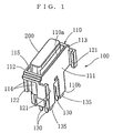
- Fig. 1 is a perspective view of the first embodiment of the fuse holder according to the present invention with a fuse being fitted.
- the fuse holder is seen from the top side thereof.
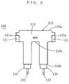
- Fig. 2 is a front view of the first embodiment of the fuse holder.
- Fig. 3 is a rear view of the first embodiment of the fuse holder.
- Fig. 4 is a plan view of the first embodiment of the fuse holder.
- Fig. 5 is a bottom view of the first embodiment of the fuse holder.
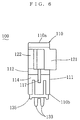
- Fig. 6 is a side view of the first embodiment of the fuse holder.
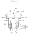
- Fig. 7 is a sectional view of the first embodiment of the fuse holder cut in both the left wall and the right wall thereof.
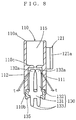
- Fig. 8 is a sectional view of the first embodiment of the fuse holder cut in both the front wall and the rear wall thereof.
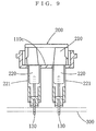
- Fig. 9 is a sectional view of the first embodiment of the fuse holder with the fuse being fitted.
- the fuse holder is cut in both the left wall and the right wall thereof.
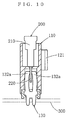
- Fig. 10 is a sectional view of the first embodiment of the fuse holder with the fuse being fitted.
- the fuse holder is cut in both the front wall and the rear wall thereof.
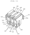
- Fig. 11 is a perspective view of the fuse holders of the first embodiment.
- the fuse folders are coupled to each other, and they are seen from the top side thereof.
- Fig. 12 is a perspective view showing the procedure for coupling the fuse holders of the first embodiment to each other.
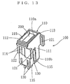
- Fig. 13 is a perspective view of the second embodiment of the fuse holder according to the present invention.
- the fuse holder with a fuse fitted is seen from the top side.
- Fig. 14 is a front view of the second embodiment of the fuse holder.
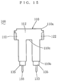
- Fig. 15 is a rear view of the second embodiment of the fuse holder.
- Fig. 16 is a plan view of the second embodiment of the fuse holder.
- Fig. 17 is a bottom view of the second embodiment of the fuse holder.
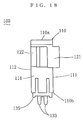
- Fig. 18 is a side view of the second embodiment of the fuse holder.
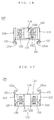
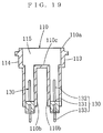
- Fig. 19 is a sectional view of the second embodiment of the fuse holder cut in the left wall and the right wall thereof.
- Fig. 20 is a sectional view of the second embodiment of the fuse holder cut in the front wall and the rear wall thereof.
- Fig. 21 is a sectional view of the second embodiment of the fuse holder with the fuse being fitted.
- the fuse holder is cut in both the left wall and the right wall thereof.
- Fig. 22 is a sectional view of the second embodiment of the fuse holder with the fuse being fitted.
- the fuse holder is cut in both the front wall and the rear wall thereof.
- Fig. 23 is a perspective view of the fuse holders of the second embodiment.
- the fuse folders are coupled to each other, and they are seen from the top side thereof.
- Fig. 24 is a perspective view showing the procedure for coupling the fuse holders of the second embodiment to each other.
- Fig. 25 is a sectional view of the third embodiment of the fuse holder.
- the fuse holder is cut in both the left wall and the right wall thereof.
- Fig. 26 is a sectional view of the third embodiment of the fuse holder.
- the fuse holder is cut in both the front wall and the rear wall thereof.
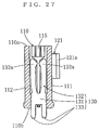
- Fig. 27 is a sectional view of the fourth embodiment of the fuse holder.
- the fuse holder is cut in both the front wall and the rear wall thereof.
- Fig. 28 is a sectional view of the fifth embodiment of the fuse holder.
- the fuse holder is cut in both the left wall and the right wall.
- Fig. 29 is a bottom view of the fifth embodiment of the fuse holder.
- Fig. 30 is an enlarged view showing the leg of the contact of the sixth embodiment of the fuse holder.
- Fig. 31 is an enlarged view showing a modification of the leg of the contact of the sixth embodiment of the fuse holder.
- a fuse to be fitted into this fuse holder is a blade type fuse 200, as shown in Fig. 9 or Fig. 10 and Fig. 21 and Fig. 22, with two blade terminals 220 protruding from the body 210 thereof.
- These fuses 200 have been standardized.
- the larger fuse 200 shown in Fig. 9 and Fig. 10 is of the maxi type, and the smaller fuse 200 shown in Fig. 21 and Fig. 22 is of the mini type.
- FIG. 2 through Fig. 8 show the first embodiment of a fuse holder 100.
- a fuse 200 of the maxi type is fitted into this fuse holder 100 (please refer to Fig. 1).
- This fuse holder 100 comprises a holder housing 110 being made of an insulator and two contacts 130 being made of a conductor and provided on the holder housing 110.
- the holder housing 110 is provided with wide walls 111, 112 at the front and the rear, and narrow walls 113, 114 on the left and the right thereof.
- a chamber 115 which is through from the top 110a to the bottom 110b of the holder housing 110, is formed on the inner sides of the front wall 111, the rear wall 112, the left wall 113 and the right wall 114.
- the front, rear, left and right herein are used for convenience to indicate relative positional relationships. Accordingly, these directions are not related to the orientations of a printed circuit board 300, onto which the fuse holder 100 is to be mounted, and the casing or the like, into which the printed circuit board 300 is to be loaded.
- the blade terminals 220 of the fuse 200 and at least a part of the body 210 thereof will be held in the chamber 115.
- a portion of the holder housing 110 from a point between the top 110a and the bottom 110b and to the top 110a overhangs in the direction of alignment of the blade terminals 220.
- the body 210 of the fuse 200 is held by a horizontal wall 110c, which is inside the overhanging part.
- the holder housing 110 is provided with two coupling parts 121, 122. These coupling parts 121, 122 can be disconnectably fitted with two other fuse holders 100 being adjacent to the holder housing 100. Modes of the fitting include modes of fitting by insertion and modes of fitting by frictional force, which are exemplified by Velcro fastener.
- two coupling parts 121, 122 fit into the coupling parts 121, 122 of the counterpart fuse holders 100.
- the first coupling part 121 comprises two plates, which are provided on the front wall 111 and have top ends 121a opposing to each other. In plan view, one plate has an inverted L shape, and the other plate has an inverted reversed L shape.
- the second coupling part 122 comprises ribs, which are provided on the left wall 113 and the right wall 114.
- the second coupling part 122 extends along the left wall 113 and the right wall 114 in the height direction thereof, and will be held between the top ends 121a of the first coupling part 121 and the front wall 111, on which the first coupling part 121 is provided.
- the coupling parts 121, 122 are integrally formed on the walls 111, 113, 114 of the holder housing 110, and they are formed simultaneously with the holder housing 110.
- two fuse holders 100 are held together in such a way that a front wall 111 opposes to a rear wall 112 and the two fuse holders 100 are staggered to each other in the direction of height. Then the top ends 121a of the first coupling part 121 of the fuse holder 100 are fitted into the second coupling part 122 of the other fuse holder 100, and the two fuse holders 100 are slid to each other to complete the fitting-in. Thus the two fuse holders 100 are coupled together.
- the present invention does not limit the locations of the coupling parts 121, 122 to the front wall 111, the left wall 113 and the right wall 114.
- the coupling parts 121, 122 may be provided on other walls.
- Slits 117 into which the side edges 221 of the blade terminals 220 are to be fitted, are provided in the left wall 113 and the right wall 114 of the holder housing 110.
- each contact 130 is fixed to the bottom 110b of the holder housing 110.
- a fork-shaped connecting part 132 is provided on one end of the contact 130 to extend towards the inside of the chamber 115.
- This connecting part 132 is formed approximately into a U shape, and its two branches 132a are arranged to expand towards the front wall 111 and the rear wall 112 to fit with the blade terminal 220 with a certain contact pressure.
- a leg 133 is provided on the other end of the contact 130 to extend out of the holder housing 110. This leg 133 is soldered or press-fitted onto a printed circuit board 300.
- the intermediate part 131 of the contact 130 is enveloped-cast in an insert 135, and the insert 135 is fitted into a space among the walls 111 through 114 at the bottom 110b of the holder housing 110.
- Enveloped-casting means that a material in a molten state adheres to and envelops an object and then solidifies over the object.
- the leg 133 of the contact 130 is forked into two branches. In other words, it has two ends.
- the clearances t between the connecting part 132 and the front wall 111 and the rear wall 112 of the holder housing 110 are set in such a way that they allow deformation of the connecting part 132 while limiting its excessive deformation.
- the clearances t are provided not to hinder expansion of the two branches 132a of the connecting part 132 when they are properly pushed by the blade terminal 220 to expand towards the front wall 111 and the rear wall 112.
- the clearances t are provided to hold and prevent excessive deformation of the two branches 132a when they are pried by the blade terminal 220.
- fuses 200 When conductive parts such as electric wires are connected to the pattern of the printed circuit board 300, the fuses 200 will be electrically connected to the conductive parts.
- a desired fuse fitting device When the printed circuit board 300 is loaded into a casing or the like, a desired fuse fitting device will be produced. With the use of this fuse holder 100, a fuse fitting device can be produced easily for any number of fuses 200 to be used without newly designing a block. Thus the production cost is reduced.
- fuses 200 may be fitted into the fuse holders 100 after the plurality of fuse holders 100 being coupled together by means of the coupling parts 121, 122 have been mounted on a printed circuit board 300.
- the present invention does not limit the configuration of the connecting part of the contact.
- the present invention includes embodiments wherein the connecting part is formed with a coiled spring and the contact pressure between the contact and the blade terminal is secured by the coiled spring.
- the connecting part 132 of the contact 130 is formed into a fork shape that can expand towards the front wall 111 and the rear wall 112, and the clearances t between the connecting part 132 and the front wall 111 and the rear wall 112 of the holder housing 110 are set to allow deformation of the connecting part 132 while limiting its excessive deformation.
- the production cost is lower in comparison with a case wherein contacts with coiled spring ends are used.
- the connecting part 132 of the contact 130 When the connecting part 132 of the contact 130 is deformed, the connecting part 132 will be restrained from excessive deformation by the front wall 111 and the rear wall 112 of the holder housing 110, and in turn, the connecting part 132 will be prevented from being pried by the blade terminal 220.
- the present invention does not limit the configuration of the coupling parts by the first embodiment.
- the first coupling part 121 comprises two plates, which are provided on the front wall 111 and have top ends 121a opposing to each other. In plan view, one plate has an inverted L shape, and the other plate has an inverted reversed L shape.
- the second coupling part 122 comprises ribs, which are formed on walls in the height direction to fit with the top ends 121a of the first coupling part 121.
- both the fuse holders 100, 100 will be coupled together. In this way, a desired number of the fuse holders 100 of the same configuration can be coupled together.
- the present invention includes embodiments wherein the holder housing is not provided with any slit.
- the holder housing 110 is provided with slits 117. With this arrangement, fitting the side edges 221 into the slits 117 will accurately determine the relative positions of the fuse 200 and the fuse holder 100 to each other, and the blade terminals 220 will be prevented from prying the connecting parts 132. Moreover, the fuse 200 will be held more securely in the fuse holder 100.
- the present invention does not limit the structure for fixing the intermediate part of the contact to the holder housing.
- the intermediate part 131 of the contact 130 is enveloped-cast in an insert 135, and this insert 135 is fitted into a space among the walls 111 through 114 at the bottom 110b of the holder housing 110.
- molding of the holder housing 110 and enveloped-casting of the inserts 135 are made separately, and they can be molded under their respective optimal conditions.
- the present invention does not limit the configuration of the leg 133 of the contact 130.
- the leg 133 of the contact 130 is formed into two branches. With this arrangement, the contact 130 will be connected to the printed circuit board 300 at two points, and defective connection will hardly occur.
- Fig. 13 through Fig. 24 show the second embodiment of a fuse holder 100.
- a mini-type fuse 200 is fitted into this fuse holder 100.
- no slit 117 is provided.
- Fig. 25 and Fig. 26 show the third embodiment of a fuse holder.
- This embodiment differs from the first embodiment in the method of fixing the contact 130 to the holder housing 110.
- the intermediate parts 131 of the contacts 130 are press-fitted into a space between the walls 111, 112 at the bottom 110b of the holder housing 110. With this arrangement, the operation is simpler among the production methods of separately forming the contacts 130 and the holder housing 110 and assembling them together.
- Fig. 27 shows the fourth embodiment of a fuse holder.
- the fourth embodiment differs from the first embodiment in the method of fixing the contacts 130 to the holder housing 110.
- the intermediate parts 131 of the contacts 130 are enveloped-cast in the holder housing 110.
- contacts 130 are set in a mold for the holder housing 110, then the material is filled into the mold to form the holder housing 110. In this way, the relative positions of the contacts 130 and the holder housing 110 to each other will be determined with high precision.
- Fig. 28 and Fig. 29 show the fifth embodiment of a fuse holder.
- the fifth embodiment differs from the first embodiment in the configuration of the insert.
- the two inserts 135 corresponding to the respective contacts 130 are coupled by a bridge 136.
- inserting the inserts 135 having the contact 130 into the holder housing 110 can be done by a single operation.
- two bosses 118, 119 are provided on the bottom 110b of the holder housing 110. These bosses 118, 119 are provided in positions that are asymmetric to each other in relation to a line L, which runs, when seen from the bottom, between the front wall 111 and the rear wall 112 approximately in parallel with these walls.
- a line L which runs, when seen from the bottom, between the front wall 111 and the rear wall 112 approximately in parallel with these walls.
- the present invention does not limit the material of the insert 135.
- the insert 135 is formed of a material, of which heat resistance is superior to that of the holder housing 110, the heat resistance of the holder housing 110 will not pose any problem even if the inserts 135 are subjected to heat of soldering.
- the holder housing 110 can be made of a more inexpensive material.
- Fig. 30 and Fig. 31 show the sixth embodiment of a fuse holder.
- a protrusion 133a is formed in the leg 133 of the contact 130.
- This protrusion 133a is also called a clinch.
- the protrusion 133a may be formed, as shown in Fig. 30, by bending the leg 133 sidewise to form a V shape, or as shown in Fig. 31, by making a part of the leg 133 protrude sidewise.
- the body 210 of the maxi-type fuse 200 which is used in the first embodiment, is provided with a rib on each side end thereof.
- the rib is formed parallel to the extending direction of the blade terminals 220.
- U-shaped supporting parts which fit with the ribs of the body 210 of the fuse 200, may be provided on the tops of the left wall 113 and the right wall 114 of the holder housing 110.
- the present invention does not limit the color of the holder housing 110. However, if the holder housing 110 has the same color as that of the body 210 of the fuse 200, the proper fuse 200 for the fuse holder 100 can be identified easily.
- the present invention includes embodiments that combine features of the above-mentioned embodiments.
- the second fuse holder is a fuse holder as recited in the above-mentioned first fuse holder, wherein the connecting part of the contact is formed into a fork shape, which can be expanded towards the front wall and the rear wall of the holder housing, and the clearances between the connecting part and the front wall and the rear wall are set in such a way that they allow deformation of the connecting part while limiting its excessive deformation.
- the contact has a fork shape, the production cost is lower than that of a contact having a coiled spring at the top end thereof.
- the connecting part of the contact When the connecting part of the contact is deformed, the connecting part will be prevented from excessive deformation by the front wall and the rear wall of the holder housing, thus the connecting part will be prevented from being pried by the blade terminal. Hence a high level of performance of the fuse fitting device can be guaranteed.
- the third fuse holder is a fuse holder as recited in the above-mentioned first or second fuse holder, wherein, of the two coupling parts, the first coupling part comprises two plates, which are provided on a wall and have top ends opposing to each other, and in plan view, one plate has an inverted L shape, and the other plate has an inverted reversed L shape, and the second coupling part comprises ribs, which are provided on walls, extend in the height direction thereof, and will be held between the top ends of the first coupling part and the wall, on which the first coupling part is provided.
- the fourth fuse holder is a fuse holder as recited in any one of the above-mentioned first through third fuse holders, wherein the intermediate parts of the contacts are press-fitted into a space among the walls of the holder housing.
- the fifth fuse holder is a fuse holder as recited in any one of the above-mentioned first through third fuse holders, wherein the intermediate parts of the contacts are enveloped-cast in the holder housing.
- the sixth fuse holder is a fuse holder as recited in any one of the above-mentioned first through third fuse holders, wherein the intermediate part of the contact is enveloped-cast in an insert and this insert is fitted into a space among the walls of the holder housing.
- the seventh fuse holder is a fuse holder as recited in the above-mentioned sixth fuse holder, wherein two inserts are coupled together. With this arrangement, inserting the inserts having the contact into the holder housing can be done by a single operation. Thus the efficiency of the assembly can be enhanced.
- the eighth fuse holder is a fuse holder as recited in the above-mentioned sixth or seventh fuse holder, wherein the insert is formed of a material, of which heat resistance is superior to that of the holder housing.
- the heat resistance of the holder housing will not pose any problem even if the insert is subjected to heat of soldering.
- the holder housing can be made of a more inexpensive material.
- the ninth fuse holder is a fuse holder as recited in any one of the above-mentioned first through eighth fuse holders, wherein the leg of the contact is forked into two branches. With this arrangement, the contact will be connected to the printed circuit board at two points, and defective connection between the fuse holder and the printed circuit board can be prevented.
- the tenth fuse holder is a fuse holder as recited in any one of the above-mentioned first through ninth fuse holders, wherein a protrusion is formed in the leg of the contact.
- the eleventh fuse holder is a fuse holder as recited in any one of the above-mentioned first through tenth fuse holders, wherein the bottom of the holder housing is provided with two bosses in positions that are asymmetric to each other in relation to a line, which runs, when seen from the bottom, between the front wall and the rear wall approximately in parallel with these walls.
- the twelfth fuse holder is a fuse holder as recited in any one of the above-mentioned first through eleventh fuse holders, wherein the holder housing has the same color as that of the body of the fuse. With this arrangement, the proper fuse for the fuse holder can be identified easily.
Landscapes
- Fuses (AREA)
- Coupling Device And Connection With Printed Circuit (AREA)
Applications Claiming Priority (2)
| Application Number | Priority Date | Filing Date | Title |
|---|---|---|---|
| JP2001047354A JP2002251952A (ja) | 2001-02-22 | 2001-02-22 | ヒューズホルダー |
| JP2001047354 | 2001-02-22 |
Publications (3)
| Publication Number | Publication Date |
|---|---|
| EP1235246A2 true EP1235246A2 (de) | 2002-08-28 |
| EP1235246A3 EP1235246A3 (de) | 2004-05-26 |
| EP1235246B1 EP1235246B1 (de) | 2007-11-28 |
Family
ID=18908802
Family Applications (1)
| Application Number | Title | Priority Date | Filing Date |
|---|---|---|---|
| EP02003841A Expired - Lifetime EP1235246B1 (de) | 2001-02-22 | 2002-02-20 | Halter für einen Sicherungseinsatz |
Country Status (5)
| Country | Link |
|---|---|
| US (1) | US6726506B2 (de) |
| EP (1) | EP1235246B1 (de) |
| JP (1) | JP2002251952A (de) |
| AT (1) | ATE379846T1 (de) |
| DE (1) | DE60223738T2 (de) |
Cited By (2)
| Publication number | Priority date | Publication date | Assignee | Title |
|---|---|---|---|---|
| CN107017479A (zh) * | 2015-10-30 | 2017-08-04 | 第精工株式会社 | 连接器端子、电连接器以及连接器端子的制造方法 |
| EP3249675A3 (de) * | 2016-05-24 | 2018-02-21 | Cooper Technologies Company | Modularer sicherungshalter und anordnung sowie verbindung davon |
Families Citing this family (24)
| Publication number | Priority date | Publication date | Assignee | Title |
|---|---|---|---|---|
| JP2003281989A (ja) * | 2002-03-25 | 2003-10-03 | Tyco Electronics Amp Kk | ブレード型ヒューズホルダ及びそれに使用されるコンタクト |
| WO2005088665A2 (en) | 2004-03-05 | 2005-09-22 | Littelfuse, Inc. | Low profile automotive fuse |
| US20060023441A1 (en) * | 2004-08-02 | 2006-02-02 | Robert Bosch Gmbh | Modularized circuit component |
| US7564337B2 (en) * | 2005-03-03 | 2009-07-21 | Littelfuse, Inc. | Thermally decoupling fuse holder and assembly |
| JP2007087823A (ja) * | 2005-09-22 | 2007-04-05 | Sumitomo Wiring Syst Ltd | バッテリー接続用のヒューズユニット |
| USD561119S1 (en) * | 2006-06-19 | 2008-02-05 | Cooper Technologies Company | Portion of a fuse holder |
| USD559203S1 (en) | 2006-11-14 | 2008-01-08 | Littelfuse, Inc. | Indicator for a fuse |
| USD575745S1 (en) | 2008-01-14 | 2008-08-26 | Littelfuse, Inc. | Blade fuse and fuse element therefore |
| US8077007B2 (en) * | 2008-01-14 | 2011-12-13 | Littlelfuse, Inc. | Blade fuse |
| USD575746S1 (en) | 2008-01-14 | 2008-08-26 | Littelfuse, Inc. | Blade fuse and fuse element therefore |
| US8105113B2 (en) * | 2010-04-21 | 2012-01-31 | Delphi Technologies, Inc. | Fuse adapter |
| JP5718661B2 (ja) * | 2011-01-28 | 2015-05-13 | 矢崎総業株式会社 | 電源回路遮断装置のヒューズ固定構造 |
| WO2013041078A1 (de) * | 2011-09-20 | 2013-03-28 | Erni Electronics Gmbh | Steckelement |
| GB201204866D0 (en) * | 2012-03-20 | 2012-05-02 | Trw Ltd | Fork type electrical connector |
| JP6019482B2 (ja) * | 2012-11-08 | 2016-11-02 | 矢崎総業株式会社 | 接続ブロック結合体 |
| US10320129B2 (en) * | 2015-03-12 | 2019-06-11 | Aees, Inc. | Low profile terminal assembly |
| CN106710996B (zh) * | 2016-12-07 | 2019-03-01 | 宁波爱维斯工贸有限公司 | 扩展式多用途保险座 |
| KR101859731B1 (ko) * | 2018-04-18 | 2018-05-18 | 주식회사 경신 | 분리형 멀티퓨즈 |
| KR101859730B1 (ko) | 2018-04-18 | 2018-05-18 | 주식회사 경신 | 분리형 멀티퓨즈 |
| KR101859729B1 (ko) | 2018-04-18 | 2018-05-18 | 주식회사 경신 | 분리형 멀티퓨즈 |
| KR101859732B1 (ko) * | 2018-04-18 | 2018-05-18 | 주식회사 경신 | 분리형 멀티퓨즈 |
| KR101859728B1 (ko) * | 2018-04-18 | 2018-05-18 | 주식회사 경신 | 분리형 멀티퓨즈 |
| US10636606B1 (en) * | 2019-03-01 | 2020-04-28 | Sumitomo Wiring Systems, Ltd. | Fuse housing assembly |
| US10916897B1 (en) | 2020-02-13 | 2021-02-09 | Aees Inc. | Battery mounted fuse holder |
Family Cites Families (43)
| Publication number | Priority date | Publication date | Assignee | Title |
|---|---|---|---|---|
| US3378808A (en) * | 1967-01-09 | 1968-04-16 | Army Usa | Electrical connector for terminating flat wire cables |
| US3848951A (en) * | 1973-01-12 | 1974-11-19 | Molex Inc | Connector housings and locking structures therefor |
| DE2511459A1 (de) * | 1975-03-15 | 1976-09-23 | Rau Swf Autozubehoer | Anordnung zur absicherung der elektrischen anlage eines motorgetriebenen fahrzeuges |
| US4094564A (en) | 1977-03-17 | 1978-06-13 | A P Products Incorporated | Multiple conductor electrical connector with ground bus |
| CH628484A5 (de) * | 1978-04-21 | 1982-02-26 | Erni & Co Elektro Ind | Verfahren und kontaktleiste zur herstellung gasdichter verbindungen fuer eine gedruckte rueckwandverdrahtung. |
| US4184733A (en) * | 1978-07-24 | 1980-01-22 | Square D Company | Segmented fanning strip |
| US4230387A (en) | 1979-04-18 | 1980-10-28 | General Staple Company, Inc. | Continuous connector |
| IT1155643B (it) * | 1982-03-17 | 1987-01-28 | Fiat Auto Spa | Blocchetto portafusibile singolo componibile per portafusibili lamellari |
| US4560227A (en) | 1983-02-04 | 1985-12-24 | Littelfuse, Inc. | Fuseholder for blade-type fuses |
| DE3478834D1 (en) * | 1983-04-07 | 1989-08-03 | Menber S Spa | A holder for plate fuses |
| DE3542349A1 (de) * | 1985-11-29 | 1987-06-04 | Bremi Auto Elektrik Ernst Brem | Vorrichtung zur halterung von elektrischen flachsteckersicherungen fuer kfz |
| DE8535226U1 (de) * | 1985-12-14 | 1986-02-06 | Bremi Auto-Elektrik Bremicker GmbH + Co, 5883 Kierspe | Fassung für elektrische Flachstecker-Schmelzsicherungen für Kfz |
| JPH079999B2 (ja) | 1987-01-31 | 1995-02-01 | 豊田合成株式会社 | 窒化ガリウム系化合物半導体発光素子 |
| JP2651411B2 (ja) | 1988-06-13 | 1997-09-10 | 日本ヘキスト・マリオン・ルセル株式会社 | アルキルアミノアセチレングリコール酸エステルの製法 |
| US4944684A (en) | 1988-06-28 | 1990-07-31 | Trw, Inc. | Electrical junction box and method for its manufacture |
| US4943248A (en) * | 1988-06-29 | 1990-07-24 | Molex Incorporated | Electrical terminal for bladed fuse |
| EP0349154A3 (de) * | 1988-06-29 | 1990-10-03 | Molex Incorporated | Elektrische Klemme und Verbinder für Messersicherungen |
| JP2732142B2 (ja) | 1990-06-21 | 1998-03-25 | 小野田エー・エル・シー株式会社 | 軽量気泡コンクリート部材並びにその製造方法及び取付構法 |
| JP2921708B2 (ja) | 1990-06-29 | 1999-07-19 | ケル株式会社 | 表面実装用電子部品 |
| US5194018A (en) | 1992-01-22 | 1993-03-16 | Molex Incorporated | Electrical connector assembly and method of fabricating same |
| JPH05342979A (ja) | 1992-06-08 | 1993-12-24 | Yazaki Corp | 暗電流用ヒューズ機構 |
| JPH06150806A (ja) | 1992-11-13 | 1994-05-31 | Yazaki Corp | ヒューズブロックにおけるミニヒューズ保持構造 |
| US5281171A (en) | 1992-12-17 | 1994-01-25 | Carrier Corporation | Fuse holding device |
| JPH06231672A (ja) | 1993-02-08 | 1994-08-19 | Yazaki Corp | ヒューズホルダ |
| JPH0725554A (ja) | 1993-07-15 | 1995-01-27 | Mitsubishi Denki Bill Techno Service Kk | エレベーター呼登録装置 |
| US5424896A (en) * | 1993-08-12 | 1995-06-13 | Lsi Logic Corporation | Semiconductor package electrostatic discharge damage protection |
| JP3404832B2 (ja) | 1993-10-15 | 2003-05-12 | 住友電装株式会社 | コネクタの製造方法及びコネクタ |
| US5409399A (en) * | 1993-12-08 | 1995-04-25 | Molex Incorporated | Electrical connection assembly for mounting on a printed circuit board |
| JPH088551A (ja) | 1994-06-21 | 1996-01-12 | Maspro Denkoh Corp | 電子機器 |
| JP3083061B2 (ja) | 1995-01-20 | 2000-09-04 | 矢崎総業株式会社 | ヒューズ接続構造 |
| JP3403570B2 (ja) | 1996-03-07 | 2003-05-06 | 矢崎総業株式会社 | ヒューズホルダ |
| US5785537A (en) * | 1996-06-26 | 1998-07-28 | Robinson Nugent, Inc. | Electrical connector interlocking apparatus |
| US5752856A (en) | 1996-07-30 | 1998-05-19 | The Whitaker Corporation | Sealed fuse connector |
| JPH10106697A (ja) | 1996-09-30 | 1998-04-24 | Mitsumi Electric Co Ltd | 電気コネクタ |
| JP3685908B2 (ja) * | 1997-05-30 | 2005-08-24 | 富士通コンポーネント株式会社 | 高速伝送用コネクタ |
| US6089918A (en) * | 1997-06-30 | 2000-07-18 | Yazaki Corporation | Adapter for electrical circuit components |
| US6155860A (en) * | 1998-01-31 | 2000-12-05 | Berg Technology, Inc. | Socket for electrical component |
| JP2000011850A (ja) | 1998-06-24 | 2000-01-14 | Sumitomo Wiring Syst Ltd | ヒューズおよび該ヒューズのヒューズボックスへの誤嵌合防止構造 |
| JP4297299B2 (ja) | 1999-01-22 | 2009-07-15 | 古河電気工業株式会社 | 電気接続箱 |
| JP2000299167A (ja) | 1999-04-13 | 2000-10-24 | Jst Mfg Co Ltd | 電気コネクタ |
| US6280253B1 (en) * | 1999-04-22 | 2001-08-28 | Visteon Global Technologies, Inc. | Method and apparatus for selectively connecting electrical circuits and components |
| USD461781S1 (en) | 2000-12-21 | 2002-08-20 | J.S.T. Mfg. Co., Ltd. | Fuse holder |
| US20040265235A1 (en) | 2003-06-26 | 2004-12-30 | Uzgiris Egidijus Edward | Magnetic resonance contrast-enhancing agents and method for detecting and imaging artherosclerotic plaque |
-
2001
- 2001-02-22 JP JP2001047354A patent/JP2002251952A/ja active Pending
-
2002
- 2002-02-19 US US10/080,151 patent/US6726506B2/en not_active Expired - Fee Related
- 2002-02-20 EP EP02003841A patent/EP1235246B1/de not_active Expired - Lifetime
- 2002-02-20 DE DE60223738T patent/DE60223738T2/de not_active Expired - Lifetime
- 2002-02-20 AT AT02003841T patent/ATE379846T1/de not_active IP Right Cessation
Cited By (4)
| Publication number | Priority date | Publication date | Assignee | Title |
|---|---|---|---|---|
| CN107017479A (zh) * | 2015-10-30 | 2017-08-04 | 第精工株式会社 | 连接器端子、电连接器以及连接器端子的制造方法 |
| EP3249675A3 (de) * | 2016-05-24 | 2018-02-21 | Cooper Technologies Company | Modularer sicherungshalter und anordnung sowie verbindung davon |
| US10395878B2 (en) | 2016-05-24 | 2019-08-27 | Eaton Intelligent Power Limited | Modular fuse holder and arrangement and connection thereof |
| US10699866B2 (en) | 2016-05-24 | 2020-06-30 | Eaton Intelligent Power Limited | Modular fuse holder and arrangement and connection thereof |
Also Published As
| Publication number | Publication date |
|---|---|
| EP1235246A3 (de) | 2004-05-26 |
| US20020115348A1 (en) | 2002-08-22 |
| DE60223738T2 (de) | 2008-04-10 |
| ATE379846T1 (de) | 2007-12-15 |
| EP1235246B1 (de) | 2007-11-28 |
| JP2002251952A (ja) | 2002-09-06 |
| US6726506B2 (en) | 2004-04-27 |
| DE60223738D1 (de) | 2008-01-10 |
Similar Documents
| Publication | Publication Date | Title |
|---|---|---|
| EP1235246B1 (de) | Halter für einen Sicherungseinsatz | |
| EP1235245B1 (de) | Halter für einen Sicherungseinsatz | |
| US6666723B2 (en) | Multiple-fuse holder | |
| US6753753B2 (en) | Fuse | |
| CN100479283C (zh) | 配电模块及其组装方法 | |
| JPS62287542A (ja) | 電気ヒユ−ズ | |
| US6135816A (en) | Electrical connector having an improved construction for fixing shield plates to a receptacle connector | |
| JP5223591B2 (ja) | 電気接続箱 | |
| US6824398B2 (en) | Structure and method for connecting bus bars in electric junction box | |
| JP2021057115A (ja) | 電気コネクタ | |
| US7367818B2 (en) | Onboard connector | |
| US7414194B2 (en) | Bus bar wiring board and method of assembling the same | |
| KR102597768B1 (ko) | 퓨즈, 및 퓨즈의 제조 방법 | |
| US6083012A (en) | Rear combination lamp | |
| US6783392B1 (en) | Connector mounting structure | |
| KR101531315B1 (ko) | 퓨즈 및 퓨즈 장착 구조 | |
| JP3994908B2 (ja) | 自動車用電気接続箱 | |
| JP4593164B2 (ja) | マルチヒューズホルダー | |
| JPH0822762A (ja) | ヒューズの二次ショート防止構造 | |
| JP2023177073A (ja) | ジョイントバスバー | |
| EP1164052A2 (de) | Verbinderstruktur zur Verbindung eines elektrischen Teiles mit einer Leiterplatte | |
| JP3405152B2 (ja) | 中継端子の組付構造 | |
| JP2002084632A (ja) | 電気接続箱 | |
| JPH10243531A (ja) | 電気接続箱 | |
| JPH09115625A (ja) | ジョイントコネクタ |
Legal Events
| Date | Code | Title | Description |
|---|---|---|---|
| PUAI | Public reference made under article 153(3) epc to a published international application that has entered the european phase |
Free format text: ORIGINAL CODE: 0009012 |
|
| AK | Designated contracting states |
Kind code of ref document: A2 Designated state(s): AT BE CH CY DE DK ES FI FR GB GR IE IT LI LU MC NL PT SE TR |
|
| AX | Request for extension of the european patent |
Free format text: AL;LT;LV;MK;RO;SI |
|
| PUAL | Search report despatched |
Free format text: ORIGINAL CODE: 0009013 |
|
| AK | Designated contracting states |
Kind code of ref document: A3 Designated state(s): AT BE CH CY DE DK ES FI FR GB GR IE IT LI LU MC NL PT SE TR |
|
| AX | Request for extension of the european patent |
Extension state: AL LT LV MK RO SI |
|
| 17P | Request for examination filed |
Effective date: 20040907 |
|
| AKX | Designation fees paid |
Designated state(s): AT BE CH CY DE DK ES FI FR GB GR IE IT LI LU MC NL PT SE TR |
|
| 17Q | First examination report despatched |
Effective date: 20060324 |
|
| 17Q | First examination report despatched |
Effective date: 20060324 |
|
| GRAP | Despatch of communication of intention to grant a patent |
Free format text: ORIGINAL CODE: EPIDOSNIGR1 |
|
| RIN1 | Information on inventor provided before grant (corrected) |
Inventor name: VAN DESSEL, SONNYC Inventor name: FUKUMORI, SHUICHIC |
|
| GRAS | Grant fee paid |
Free format text: ORIGINAL CODE: EPIDOSNIGR3 |
|
| GRAL | Information related to payment of fee for publishing/printing deleted |
Free format text: ORIGINAL CODE: EPIDOSDIGR3 |
|
| GRAS | Grant fee paid |
Free format text: ORIGINAL CODE: EPIDOSNIGR3 |
|
| GRAA | (expected) grant |
Free format text: ORIGINAL CODE: 0009210 |
|
| AK | Designated contracting states |
Kind code of ref document: B1 Designated state(s): AT BE CH CY DE DK ES FI FR GB GR IE IT LI LU MC NL PT SE TR |
|
| REG | Reference to a national code |
Ref country code: IE Ref legal event code: FG4D |
|
| REG | Reference to a national code |
Ref country code: CH Ref legal event code: EP |
|
| REF | Corresponds to: |
Ref document number: 60223738 Country of ref document: DE Date of ref document: 20080110 Kind code of ref document: P |
|
| ET | Fr: translation filed | ||
| PG25 | Lapsed in a contracting state [announced via postgrant information from national office to epo] |
Ref country code: NL Free format text: LAPSE BECAUSE OF FAILURE TO SUBMIT A TRANSLATION OF THE DESCRIPTION OR TO PAY THE FEE WITHIN THE PRESCRIBED TIME-LIMIT Effective date: 20071128 Ref country code: LI Free format text: LAPSE BECAUSE OF FAILURE TO SUBMIT A TRANSLATION OF THE DESCRIPTION OR TO PAY THE FEE WITHIN THE PRESCRIBED TIME-LIMIT Effective date: 20071128 Ref country code: ES Free format text: LAPSE BECAUSE OF FAILURE TO SUBMIT A TRANSLATION OF THE DESCRIPTION OR TO PAY THE FEE WITHIN THE PRESCRIBED TIME-LIMIT Effective date: 20080311 Ref country code: CH Free format text: LAPSE BECAUSE OF FAILURE TO SUBMIT A TRANSLATION OF THE DESCRIPTION OR TO PAY THE FEE WITHIN THE PRESCRIBED TIME-LIMIT Effective date: 20071128 Ref country code: SE Free format text: LAPSE BECAUSE OF FAILURE TO SUBMIT A TRANSLATION OF THE DESCRIPTION OR TO PAY THE FEE WITHIN THE PRESCRIBED TIME-LIMIT Effective date: 20080228 |
|
| NLV1 | Nl: lapsed or annulled due to failure to fulfill the requirements of art. 29p and 29m of the patents act | ||
| PG25 | Lapsed in a contracting state [announced via postgrant information from national office to epo] |
Ref country code: FI Free format text: LAPSE BECAUSE OF FAILURE TO SUBMIT A TRANSLATION OF THE DESCRIPTION OR TO PAY THE FEE WITHIN THE PRESCRIBED TIME-LIMIT Effective date: 20071128 |
|
| REG | Reference to a national code |
Ref country code: CH Ref legal event code: PL |
|
| PG25 | Lapsed in a contracting state [announced via postgrant information from national office to epo] |
Ref country code: AT Free format text: LAPSE BECAUSE OF FAILURE TO SUBMIT A TRANSLATION OF THE DESCRIPTION OR TO PAY THE FEE WITHIN THE PRESCRIBED TIME-LIMIT Effective date: 20071128 |
|
| PG25 | Lapsed in a contracting state [announced via postgrant information from national office to epo] |
Ref country code: DK Free format text: LAPSE BECAUSE OF FAILURE TO SUBMIT A TRANSLATION OF THE DESCRIPTION OR TO PAY THE FEE WITHIN THE PRESCRIBED TIME-LIMIT Effective date: 20071128 |
|
| PG25 | Lapsed in a contracting state [announced via postgrant information from national office to epo] |
Ref country code: BE Free format text: LAPSE BECAUSE OF FAILURE TO SUBMIT A TRANSLATION OF THE DESCRIPTION OR TO PAY THE FEE WITHIN THE PRESCRIBED TIME-LIMIT Effective date: 20071128 |
|
| PG25 | Lapsed in a contracting state [announced via postgrant information from national office to epo] |
Ref country code: PT Free format text: LAPSE BECAUSE OF FAILURE TO SUBMIT A TRANSLATION OF THE DESCRIPTION OR TO PAY THE FEE WITHIN THE PRESCRIBED TIME-LIMIT Effective date: 20080428 |
|
| PLBE | No opposition filed within time limit |
Free format text: ORIGINAL CODE: 0009261 |
|
| STAA | Information on the status of an ep patent application or granted ep patent |
Free format text: STATUS: NO OPPOSITION FILED WITHIN TIME LIMIT |
|
| PG25 | Lapsed in a contracting state [announced via postgrant information from national office to epo] |
Ref country code: MC Free format text: LAPSE BECAUSE OF NON-PAYMENT OF DUE FEES Effective date: 20080228 |
|
| 26N | No opposition filed |
Effective date: 20080829 |
|
| PG25 | Lapsed in a contracting state [announced via postgrant information from national office to epo] |
Ref country code: IE Free format text: LAPSE BECAUSE OF NON-PAYMENT OF DUE FEES Effective date: 20080220 Ref country code: GR Free format text: LAPSE BECAUSE OF FAILURE TO SUBMIT A TRANSLATION OF THE DESCRIPTION OR TO PAY THE FEE WITHIN THE PRESCRIBED TIME-LIMIT Effective date: 20080229 |
|
| PG25 | Lapsed in a contracting state [announced via postgrant information from national office to epo] |
Ref country code: CY Free format text: LAPSE BECAUSE OF FAILURE TO SUBMIT A TRANSLATION OF THE DESCRIPTION OR TO PAY THE FEE WITHIN THE PRESCRIBED TIME-LIMIT Effective date: 20071128 |
|
| PG25 | Lapsed in a contracting state [announced via postgrant information from national office to epo] |
Ref country code: LU Free format text: LAPSE BECAUSE OF NON-PAYMENT OF DUE FEES Effective date: 20080220 |
|
| PG25 | Lapsed in a contracting state [announced via postgrant information from national office to epo] |
Ref country code: TR Free format text: LAPSE BECAUSE OF FAILURE TO SUBMIT A TRANSLATION OF THE DESCRIPTION OR TO PAY THE FEE WITHIN THE PRESCRIBED TIME-LIMIT Effective date: 20071128 |
|
| PG25 | Lapsed in a contracting state [announced via postgrant information from national office to epo] |
Ref country code: IT Free format text: LAPSE BECAUSE OF NON-PAYMENT OF DUE FEES Effective date: 20080229 |
|
| PGFP | Annual fee paid to national office [announced via postgrant information from national office to epo] |
Ref country code: DE Payment date: 20110224 Year of fee payment: 10 Ref country code: FR Payment date: 20110301 Year of fee payment: 10 |
|
| PGFP | Annual fee paid to national office [announced via postgrant information from national office to epo] |
Ref country code: GB Payment date: 20110221 Year of fee payment: 10 |
|
| GBPC | Gb: european patent ceased through non-payment of renewal fee |
Effective date: 20120220 |
|
| REG | Reference to a national code |
Ref country code: FR Ref legal event code: ST Effective date: 20121031 |
|
| REG | Reference to a national code |
Ref country code: DE Ref legal event code: R119 Ref document number: 60223738 Country of ref document: DE Effective date: 20120901 |
|
| PG25 | Lapsed in a contracting state [announced via postgrant information from national office to epo] |
Ref country code: GB Free format text: LAPSE BECAUSE OF NON-PAYMENT OF DUE FEES Effective date: 20120220 Ref country code: FR Free format text: LAPSE BECAUSE OF NON-PAYMENT OF DUE FEES Effective date: 20120229 |
|
| PG25 | Lapsed in a contracting state [announced via postgrant information from national office to epo] |
Ref country code: DE Free format text: LAPSE BECAUSE OF NON-PAYMENT OF DUE FEES Effective date: 20120901 |