EP1238750A2 - Hohlstabilisator und sein Herstellungsverfahren - Google Patents
Hohlstabilisator und sein Herstellungsverfahren Download PDFInfo
- Publication number
- EP1238750A2 EP1238750A2 EP02005196A EP02005196A EP1238750A2 EP 1238750 A2 EP1238750 A2 EP 1238750A2 EP 02005196 A EP02005196 A EP 02005196A EP 02005196 A EP02005196 A EP 02005196A EP 1238750 A2 EP1238750 A2 EP 1238750A2
- Authority
- EP
- European Patent Office
- Prior art keywords
- stabilizer
- pipe
- hollow stabilizer
- hollow
- surface portion
- Prior art date
- Legal status (The legal status is an assumption and is not a legal conclusion. Google has not performed a legal analysis and makes no representation as to the accuracy of the status listed.)
- Granted
Links
- 239000003381 stabilizer Substances 0.000 title claims abstract description 112
- 238000004519 manufacturing process Methods 0.000 title claims abstract description 25
- 238000005480 shot peening Methods 0.000 claims abstract description 28
- 238000010438 heat treatment Methods 0.000 claims abstract description 17
- 238000000576 coating method Methods 0.000 claims abstract description 8
- 239000011248 coating agent Substances 0.000 claims abstract description 7
- 230000003116 impacting effect Effects 0.000 claims abstract description 5
- 238000005452 bending Methods 0.000 claims description 21
- 239000000463 material Substances 0.000 claims description 20
- 239000007787 solid Substances 0.000 description 18
- 238000000034 method Methods 0.000 description 12
- 230000006835 compression Effects 0.000 description 10
- 238000007906 compression Methods 0.000 description 10
- 238000013461 design Methods 0.000 description 10
- 239000011324 bead Substances 0.000 description 6
- 230000015572 biosynthetic process Effects 0.000 description 5
- 230000008859 change Effects 0.000 description 5
- 238000012360 testing method Methods 0.000 description 5
- XLYOFNOQVPJJNP-UHFFFAOYSA-N water Substances O XLYOFNOQVPJJNP-UHFFFAOYSA-N 0.000 description 5
- 230000008569 process Effects 0.000 description 4
- 230000000694 effects Effects 0.000 description 3
- 238000012545 processing Methods 0.000 description 3
- 238000005496 tempering Methods 0.000 description 3
- 229910000831 Steel Inorganic materials 0.000 description 2
- 238000000137 annealing Methods 0.000 description 2
- 230000007547 defect Effects 0.000 description 2
- 230000002093 peripheral effect Effects 0.000 description 2
- 230000009467 reduction Effects 0.000 description 2
- 150000003839 salts Chemical class 0.000 description 2
- 239000010959 steel Substances 0.000 description 2
- 230000009466 transformation Effects 0.000 description 2
- 230000008901 benefit Effects 0.000 description 1
- 239000003795 chemical substances by application Substances 0.000 description 1
- 238000010622 cold drawing Methods 0.000 description 1
- 238000001816 cooling Methods 0.000 description 1
- 238000001514 detection method Methods 0.000 description 1
- 238000005516 engineering process Methods 0.000 description 1
- 238000007429 general method Methods 0.000 description 1
- 238000002360 preparation method Methods 0.000 description 1
- 238000005096 rolling process Methods 0.000 description 1
- 238000005482 strain hardening Methods 0.000 description 1
- 238000003466 welding Methods 0.000 description 1
Images



Classifications
-
- B—PERFORMING OPERATIONS; TRANSPORTING
- B23—MACHINE TOOLS; METAL-WORKING NOT OTHERWISE PROVIDED FOR
- B23P—METAL-WORKING NOT OTHERWISE PROVIDED FOR; COMBINED OPERATIONS; UNIVERSAL MACHINE TOOLS
- B23P15/00—Making specific metal objects by operations not covered by a single other subclass or a group in this subclass
-
- B—PERFORMING OPERATIONS; TRANSPORTING
- B60—VEHICLES IN GENERAL
- B60G—VEHICLE SUSPENSION ARRANGEMENTS
- B60G21/00—Interconnection systems for two or more resiliently-suspended wheels, e.g. for stabilising a vehicle body with respect to acceleration, deceleration or centrifugal forces
- B60G21/02—Interconnection systems for two or more resiliently-suspended wheels, e.g. for stabilising a vehicle body with respect to acceleration, deceleration or centrifugal forces permanently interconnected
- B60G21/04—Interconnection systems for two or more resiliently-suspended wheels, e.g. for stabilising a vehicle body with respect to acceleration, deceleration or centrifugal forces permanently interconnected mechanically
- B60G21/05—Interconnection systems for two or more resiliently-suspended wheels, e.g. for stabilising a vehicle body with respect to acceleration, deceleration or centrifugal forces permanently interconnected mechanically between wheels on the same axle but on different sides of the vehicle, i.e. the left and right wheel suspensions being interconnected
- B60G21/055—Stabiliser bars
-
- B—PERFORMING OPERATIONS; TRANSPORTING
- B60—VEHICLES IN GENERAL
- B60G—VEHICLE SUSPENSION ARRANGEMENTS
- B60G21/00—Interconnection systems for two or more resiliently-suspended wheels, e.g. for stabilising a vehicle body with respect to acceleration, deceleration or centrifugal forces
- B60G21/02—Interconnection systems for two or more resiliently-suspended wheels, e.g. for stabilising a vehicle body with respect to acceleration, deceleration or centrifugal forces permanently interconnected
- B60G21/04—Interconnection systems for two or more resiliently-suspended wheels, e.g. for stabilising a vehicle body with respect to acceleration, deceleration or centrifugal forces permanently interconnected mechanically
- B60G21/05—Interconnection systems for two or more resiliently-suspended wheels, e.g. for stabilising a vehicle body with respect to acceleration, deceleration or centrifugal forces permanently interconnected mechanically between wheels on the same axle but on different sides of the vehicle, i.e. the left and right wheel suspensions being interconnected
- B60G21/055—Stabiliser bars
- B60G21/0551—Mounting means therefor
-
- B—PERFORMING OPERATIONS; TRANSPORTING
- B23—MACHINE TOOLS; METAL-WORKING NOT OTHERWISE PROVIDED FOR
- B23P—METAL-WORKING NOT OTHERWISE PROVIDED FOR; COMBINED OPERATIONS; UNIVERSAL MACHINE TOOLS
- B23P2700/00—Indexing scheme relating to the articles being treated, e.g. manufactured, repaired, assembled, connected or other operations covered in the subgroups
- B23P2700/14—Suspension elements of automobile vehicles
-
- B—PERFORMING OPERATIONS; TRANSPORTING
- B60—VEHICLES IN GENERAL
- B60G—VEHICLE SUSPENSION ARRANGEMENTS
- B60G2204/00—Indexing codes related to suspensions per se or to auxiliary parts
- B60G2204/10—Mounting of suspension elements
- B60G2204/12—Mounting of springs or dampers
- B60G2204/122—Mounting of torsion springs
- B60G2204/1222—Middle mounts of stabiliser on vehicle body or chassis
-
- B—PERFORMING OPERATIONS; TRANSPORTING
- B60—VEHICLES IN GENERAL
- B60G—VEHICLE SUSPENSION ARRANGEMENTS
- B60G2204/00—Indexing codes related to suspensions per se or to auxiliary parts
- B60G2204/10—Mounting of suspension elements
- B60G2204/12—Mounting of springs or dampers
- B60G2204/122—Mounting of torsion springs
- B60G2204/1224—End mounts of stabiliser on wheel suspension
-
- B—PERFORMING OPERATIONS; TRANSPORTING
- B60—VEHICLES IN GENERAL
- B60G—VEHICLE SUSPENSION ARRANGEMENTS
- B60G2204/00—Indexing codes related to suspensions per se or to auxiliary parts
- B60G2204/40—Auxiliary suspension parts; Adjustment of suspensions
- B60G2204/416—Ball or spherical joints
-
- B—PERFORMING OPERATIONS; TRANSPORTING
- B60—VEHICLES IN GENERAL
- B60G—VEHICLE SUSPENSION ARRANGEMENTS
- B60G2204/00—Indexing codes related to suspensions per se or to auxiliary parts
- B60G2204/40—Auxiliary suspension parts; Adjustment of suspensions
- B60G2204/422—Links for mounting suspension elements
-
- B—PERFORMING OPERATIONS; TRANSPORTING
- B60—VEHICLES IN GENERAL
- B60G—VEHICLE SUSPENSION ARRANGEMENTS
- B60G2204/00—Indexing codes related to suspensions per se or to auxiliary parts
- B60G2204/40—Auxiliary suspension parts; Adjustment of suspensions
- B60G2204/44—Centering or positioning means
-
- B—PERFORMING OPERATIONS; TRANSPORTING
- B60—VEHICLES IN GENERAL
- B60G—VEHICLE SUSPENSION ARRANGEMENTS
- B60G2204/00—Indexing codes related to suspensions per se or to auxiliary parts
- B60G2204/40—Auxiliary suspension parts; Adjustment of suspensions
- B60G2204/45—Stops limiting travel
-
- B—PERFORMING OPERATIONS; TRANSPORTING
- B60—VEHICLES IN GENERAL
- B60G—VEHICLE SUSPENSION ARRANGEMENTS
- B60G2204/00—Indexing codes related to suspensions per se or to auxiliary parts
- B60G2204/80—Interactive suspensions; arrangement affecting more than one suspension unit
- B60G2204/82—Interactive suspensions; arrangement affecting more than one suspension unit left and right unit on same axle
-
- B—PERFORMING OPERATIONS; TRANSPORTING
- B60—VEHICLES IN GENERAL
- B60G—VEHICLE SUSPENSION ARRANGEMENTS
- B60G2204/00—Indexing codes related to suspensions per se or to auxiliary parts
- B60G2204/80—Interactive suspensions; arrangement affecting more than one suspension unit
- B60G2204/83—Type of interconnection
- B60G2204/8302—Mechanical
-
- B—PERFORMING OPERATIONS; TRANSPORTING
- B60—VEHICLES IN GENERAL
- B60G—VEHICLE SUSPENSION ARRANGEMENTS
- B60G2204/00—Indexing codes related to suspensions per se or to auxiliary parts
- B60G2204/80—Interactive suspensions; arrangement affecting more than one suspension unit
- B60G2204/83—Type of interconnection
- B60G2204/8306—Permanent; Continuous
-
- B—PERFORMING OPERATIONS; TRANSPORTING
- B60—VEHICLES IN GENERAL
- B60G—VEHICLE SUSPENSION ARRANGEMENTS
- B60G2206/00—Indexing codes related to the manufacturing of suspensions: constructional features, the materials used, procedures or tools
- B60G2206/01—Constructional features of suspension elements, e.g. arms, dampers, springs
- B60G2206/40—Constructional features of dampers and/or springs
- B60G2206/42—Springs
- B60G2206/427—Stabiliser bars or tubes
-
- B—PERFORMING OPERATIONS; TRANSPORTING
- B60—VEHICLES IN GENERAL
- B60G—VEHICLE SUSPENSION ARRANGEMENTS
- B60G2206/00—Indexing codes related to the manufacturing of suspensions: constructional features, the materials used, procedures or tools
- B60G2206/01—Constructional features of suspension elements, e.g. arms, dampers, springs
- B60G2206/70—Materials used in suspensions
- B60G2206/72—Steel
-
- B—PERFORMING OPERATIONS; TRANSPORTING
- B60—VEHICLES IN GENERAL
- B60G—VEHICLE SUSPENSION ARRANGEMENTS
- B60G2206/00—Indexing codes related to the manufacturing of suspensions: constructional features, the materials used, procedures or tools
- B60G2206/01—Constructional features of suspension elements, e.g. arms, dampers, springs
- B60G2206/80—Manufacturing procedures
-
- B—PERFORMING OPERATIONS; TRANSPORTING
- B60—VEHICLES IN GENERAL
- B60G—VEHICLE SUSPENSION ARRANGEMENTS
- B60G2206/00—Indexing codes related to the manufacturing of suspensions: constructional features, the materials used, procedures or tools
- B60G2206/01—Constructional features of suspension elements, e.g. arms, dampers, springs
- B60G2206/80—Manufacturing procedures
- B60G2206/81—Shaping
- B60G2206/8103—Shaping by folding or bending
-
- B—PERFORMING OPERATIONS; TRANSPORTING
- B60—VEHICLES IN GENERAL
- B60G—VEHICLE SUSPENSION ARRANGEMENTS
- B60G2206/00—Indexing codes related to the manufacturing of suspensions: constructional features, the materials used, procedures or tools
- B60G2206/01—Constructional features of suspension elements, e.g. arms, dampers, springs
- B60G2206/80—Manufacturing procedures
- B60G2206/81—Shaping
- B60G2206/8103—Shaping by folding or bending
- B60G2206/81035—Shaping by folding or bending involving heating to relieve internal stresses
-
- B—PERFORMING OPERATIONS; TRANSPORTING
- B60—VEHICLES IN GENERAL
- B60G—VEHICLE SUSPENSION ARRANGEMENTS
- B60G2206/00—Indexing codes related to the manufacturing of suspensions: constructional features, the materials used, procedures or tools
- B60G2206/01—Constructional features of suspension elements, e.g. arms, dampers, springs
- B60G2206/80—Manufacturing procedures
- B60G2206/82—Joining
- B60G2206/8201—Joining by welding
-
- B—PERFORMING OPERATIONS; TRANSPORTING
- B60—VEHICLES IN GENERAL
- B60G—VEHICLE SUSPENSION ARRANGEMENTS
- B60G2206/00—Indexing codes related to the manufacturing of suspensions: constructional features, the materials used, procedures or tools
- B60G2206/01—Constructional features of suspension elements, e.g. arms, dampers, springs
- B60G2206/80—Manufacturing procedures
- B60G2206/84—Hardening
-
- B—PERFORMING OPERATIONS; TRANSPORTING
- B60—VEHICLES IN GENERAL
- B60G—VEHICLE SUSPENSION ARRANGEMENTS
- B60G2206/00—Indexing codes related to the manufacturing of suspensions: constructional features, the materials used, procedures or tools
- B60G2206/01—Constructional features of suspension elements, e.g. arms, dampers, springs
- B60G2206/80—Manufacturing procedures
- B60G2206/84—Hardening
- B60G2206/8403—Shot-peening
-
- Y—GENERAL TAGGING OF NEW TECHNOLOGICAL DEVELOPMENTS; GENERAL TAGGING OF CROSS-SECTIONAL TECHNOLOGIES SPANNING OVER SEVERAL SECTIONS OF THE IPC; TECHNICAL SUBJECTS COVERED BY FORMER USPC CROSS-REFERENCE ART COLLECTIONS [XRACs] AND DIGESTS
- Y10—TECHNICAL SUBJECTS COVERED BY FORMER USPC
- Y10T—TECHNICAL SUBJECTS COVERED BY FORMER US CLASSIFICATION
- Y10T29/00—Metal working
- Y10T29/49—Method of mechanical manufacture
- Y10T29/49616—Structural member making
- Y10T29/49622—Vehicular structural member making
Definitions
- the present invention relates to a method of manufacturing a hollow stabilizer used for vehicles such as automobiles or the like, and more particularly, relates to a technology for increasing durability as much as possible.
- a stabilizer includes a solid stabilizer using a round bar as a material, and a hollow stabilizer using a pipe as a material for the purpose of saving weight.
- a spring constant is set for each type of automobile in order to obtain the roll rigidity required for the automobile.
- a wire diameter is selected for the solid stabilizer.
- the outer diameter of the hollow stabilizer necessarily becomes larger than the wire diameter of the solid stabilizer in order to maintain the roll rigidity.
- the generated stress is larger in the hollow stabilizer.
- An increasing rate of stress depends on the thickness ratio (thickness t/outer diameter D) of the steel pipe constituting the pipe and a weight saving rate required in the hollow stabilizer.
- Fig. 6 shows a flow of a general method of manufacturing a conventional hollow stabilizer.
- An inexpensive electroseamed pipe is employed as a material of the hollow stabilizer, and the electroseamed pipe is cut at a predetermined length and is bent in a stabilizer shape.
- An NC bender or the like is used for the bending formation.
- the NC bender in order to restrict the compression of the material at the time of bending, the bending operation is executed while clamping an outer periphery of the electroseamed pipe by a bending roll and a bending piece moving along an outer periphery of the bending roll.
- a heat treatment comprising a heating, a hardening, and a tempering is applied to a bent product, a shot peening is applied thereto, and thereafter, a coating process is applied thereto, whereby the hollow stabilizer is formed.
- the hollow stabilizer is formed by a material constituted by a thin electroseamed pipe having a thickness ratio (t/D) between 10 and 17%. Further more, a bead formed at the time of welding is left on an inner peripheral surface of the electroseamed pipe, constituting a defect. Accordingly, in order to make it possible to change the design to the hollow stabilizer formed by the electroseamed pipe as the material, it is necessary to consider an application of a heat treatment, a minimization of damage such as the compression of the bent portion due to the contrivance of the bending method, a detection and control of a bead position, an application of the shot peening and the like.
- an inner surface portion of the hollow stabilizer to which the shot peening is not generally applied sometimes becomes a portion having the lowest fatigue strength in spite of generated stress being less than that at the outer surface. Since the thickness ratio of the conventional hollow stabilizer is generally about 15%, a difference in stress between the outer surface portion and the inner surface portion is small. As a result, a starting point of a fatigue failure frequently moves from the outer surface portion to the inner surface portion due to the shot peening. Accordingly, in order not to halve an effect obtained by applying the shot peening to the outer surface portion, it is desirable to make the design so that the inner surface portion is not the starting point of the fatigue failure.
- the hollow stabilizer is generally bent in a cold state by the NC bender having a general purpose.
- the compression of the material in the bent portion causes a reduction in the fatigue strength.
- Japanese Unexamined Patent Publication No. 2000-233625 there is described a manufacturing method of compressing an electroseamed pipe having a large diameter to a thickness ratio less than 0.2 in a hot state so as to form a raw pipe, drawing the raw pipe in a cold state so as to make the thickness ratio between 0.2 and 0.27, and applying a strain removing annealing and a shot peening after forming.
- the manufacturing cost becomes rather high because the drawing process is executed, and there is a problem in that the maximum thickness is limited due to a limit in a cold drawing capacity and a range of selection in the design is narrow.
- An object of the present invention is to provide a method of manufacturing a hollow stabilizer which can obtain a desired thickness in accordance with an inexpensive manufacturing step so as to obtain a required durability, whereby a range of selection in design is wide and it is possible to easily correspond to a design change from a solid stabilizer to a hollow stabilizer. Further more, another object of the present invention is to provide a hollow stabilizer which can maximally generate a fatigue failure in an outer surface portion and sufficiently achieve an effect of a shot peening applied to the outer surface portion.
- a method of manufacturing a hollow stabilizer comprising: a pipe compressing step of compressing an electroseamed pipe in a temperature range of a hot state or a warm state so as to make a rate of a thickness with respect to an outer diameter between 18 and 35%; a forming step of forming the compressed electroseamed pipe in a stabilizer shape in a cold state; a step of applying a heat treatment to a half-finished stabilizer; a shot peening step of impacting a shot on the half-finished stabilizer; and a step of coating the half-finished stabilizer.
- the electroseamed pipe is compressed in the temperature range of the hot state or the warm state having a small deformation resistance, it is possible to easily obtain a thick pipe having a large thickness ratio, even in a material having a good hardening property.
- the hot state means a temperature range equal to or greater than an A3 transformation point
- the warm state means a temperature range equal to or less than the A3 transformation point.
- the pipe compression can be executed, for example, by a multistage rolling, and the means is not limited as long as the pipe compression can be executed in the hot state or the warm state.
- the hollow stabilizer of the thin electroseamed pipe it is possible to improve the strength of the outer surface portion in accordance with the shot peening.
- a defect such as a bead or the like exists in an inner surface portion, and the processing cost of the shot peening on the inner surface is rather high, this shot peening is not executed very frequently. Accordingly, as mentioned above, in a durability test, although the stress is lower at the inner surface portion than at the outer surface, there are many cases in which the inner surface portion becomes a starting point of breakage.
- the thickness ratio is made between 18 and 35% in the pipe compression step, it is possible to make the inner diameter very small. Accordingly, the stress in the inner surface portion can be sufficiently reduced, and it is possible to minimize a reduction in service life caused by the inner surface portion.
- the shot peening is applied to the half-finished stabilizer, it is possible to broadly improve durability together with improving fatigue strength in the inner surface portion. Accordingly, it is possible to obtain a desired durability, the range of selection of the design is wide, and it is possible to easily correspond to the design change from a solid stabilizer to a hollow stabilizer.
- a bead cut of an outer periphery is normally executed; however, a bead cut of an inner periphery also be can executed. Accordingly, it can be considered that an electroseamed pipe having no inner peripheral bead is employed in some required specifications.
- the forming step of forming the electroseamed pipe in the stabilizer shape is executed in the cold state.
- an NC bender capable of forming substantially in an optional shape may be used for general purposes.
- the thickness ratio is equal to or greater than 18%, there is an advantage in that it is possible to restrict the compression of the material.
- it is desirable to set the thickness ratio after compressing the pipe to 20% or more, and it is further preferable to set it to 25% or more, or to more than 27%.
- the thickness ratio after compressing the pipe it is desirable to set the thickness ratio after compressing the pipe to 20% or more, and it is further preferable to set it to 25% or more, or to more than 27%.
- the thickness ratio is less than 18%, in the case in which the compressed state at a time of bending generates no problem in view of durability, it is possible to employ the same forming method as that of the solid stabilizer.
- the forming is executed in a cold state or the forming is executed in a hot state by employing the general mold is selected on the basis of a case in which the production amount is small and the cost is advantageous even when a tact is a little slow in comparison with a preparation of an exclusive general bending mold, or a case in which the cost is advantageous in a fast processing tact, that is, it is possible to select a method which is advantageous in cost according to particular cases.
- a method of manufacturing a hollow stabilizer comprising: a pipe compressing step of compressing an electroseamed pipe in a temperature range of a hot state or a warm state so as to make a rate of a thickness with respect to an outer diameter between 18 and 35%; a forming step of forming the compressed electroseamed pipe in a stabilizer shape in a cold state; a step of applying a heat treatment to a half-finished stabilizer; a shot peening step of impacting shot on the half-finished stabilizer; and a step of coating the half-finished stabilizer.
- the thickness ratio after compressing the pipe is made equal to or less than 35%, because the hollow stabilizer having a thickness more than 35% can hardly achieve the weight saving. Taking this point into consideration, it is desirable that the thickness ratio after compressing the pipe be equal to or less than 30%, and in this case, it is possible to achieve a weight saving equal to or greater than 20%. Further more, a hardening and a tempering are typical for the heat treatment in the present invention. In this case, it is possible to apply a stress removing annealing after processing without executing the heat treatment.
- the inventors of the present invention have researched the relationship between the thickness ratio of the hollow stabilizer and the shot peening applied to the outer surface portion.
- the inventors when applying the shot peening to the outer surface portion, there are cases in which fatigue failure is generated in the inner surface portion in which the stress is lower than that of the outer surface portion.
- the inventors have found that there is generated a strong tendency in which the fatigue failure is generated on the outer surface portion in the hollow stabilizer to which the shot peening is applied when the thickness is equal to or greater than 18%.
- the hollow stabilizer in accordance with the present invention is made on the basis of the knowledge mentioned above, and is characterized by bending the material obtained by compressing the electroseamed pipe in the temperature range of the hot state or the warm state so as to make the ratio of the thickness with respect to the outer diameter between 18 and 35%, whereby the thickness ratio is made between 18 and 35% and the shot peening is applied to the outer surface portion.
- the thickness ratio be equal to or less than 30%. Further more, it is desirable that the thickness ratio be equal to or greater than 20%, and it is further preferable that the thickness ratio be equal to or greater than 25%, and further, more than 27%.
- Fig. 1 is a flowchart showing a method of manufacturing a hollow stabilizer in accordance with the embodiment.
- an electroseamed pipe having a diameter larger than an outer diameter of a hollow stabilizer to be manufactured is compressed in a temperature range under a hot state or a warm state, whereby a thickness ratio (t/D) is made between 18 and 35% (S1).
- t/D thickness ratio
- the electroseamed pipe cut in a predetermined length is formed in a stabilizer shape in accordance with a cold working (S2).
- S2 cold working
- an NC bender can be employed for this formation.
- a press forming is applied to a terminal before or after the formation.
- a half-finished stabilizer is heated and is cast in a hardening tank so as to be hardened (S3).
- a hardening heating an electric resistance heating in which both end portions of the half-finished stabilizer are clamped by electrodes and an electric current is applied is preferable because a deformation of the half-finished product is reduced and the cost of equipment is low. In this case, it is possible to perform an ambient atmosphere heating applied by a heating furnace.
- a hardening agent in the case in which a hardening property of a material is high, a hardening oil is employed; however, in the case in which the hardening property is low, salt water may be employed in some cases. In the case of executing the hardening by using water or salt water, since the half-finished stabilizer is surrounded by water vapor and the cooling rate is reduced, it is desirable to move it in the hardening tank so as to drain off the water vapor.
- a tempering is applied to the half-finished stabilizer (S4), a shot peening is applied mainly to a shoulder portion (S5), and thereafter a coating is performed so as to obtain a hollow stabilizer.
- the above corresponds to steps in the case of forming the electroseamed pipe in a cold state; however, in the case of forming in a hot state, the right side steps in Fig. 1 apply.
- Fig. 2 is a perspective view showing a stabilizer apparatus 10 for a vehicle to which parts required for a hollow stabilizer 11 manufactured in the manner mentioned above are mounted.
- the hollow stabilizer 11 is provided with arm portions 13 and 14, and a torsion portion 15 connecting therebetween.
- a bush 21 for being mounted to a vehicle body of the vehicle is mounted to the torsion portion 15.
- a stabilizer control link 12 supported at a wheel side of the vehicle is mounted to a front end portion of each of the arm portions 13 and 14 by a stud 33.
- a thickness ratio (t/D) of the hollow stabilizer 11 is set between 18 and 35%.
- the stabilizer apparatus for the vehicle can be structured such that the arm portions 13 and 14 are mounted to the vehicle body and the torsion portion 15 is mounted to the wheel side.
- Table 1 shows respective specifications of a solid stabilizer having a wire diameter of 27 mm, and a hollow stabilizer having substantially the same spring constant as that of the solid stabilizer.
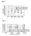
- the respective stabilizers are structured such that the heat treatment, the shot peening, and the coating are applied. Further more, main stresses at the time of imparting a deformation of the same stroke to the respective stabilizers are also described in Table 1, and the values are shown in Fig. 3.
- a sample No. 2 is a thin pipe in which a thickness ratio is 11.7%
- sample No. 5 is a thick pipe in which the thickness ratio is 27.6%.
- the main stress on an inner surface portion is 100% larger than in the thick pipe
- the main stress on an outer surface portion is 37.4% larger than in the thick pipe. Accordingly, it is expected that the durability is considerably deteriorated in comparison with the thick pipe.
- a starting point of breakage is generated on an inner surface, it is possible to infer that the durability of the thick pipe is broadly improved in comparison with that of the thin pipe.
- Fig. 4 shows a result of a durability test of a thin pipe in which the thickness ratio is 11.7% and a thick pipe in which the thickness ratio is 27.6%.
- this durability test all of the hollow stabilizers made of the thin pipes broke at the starting point of the inner surface portion, and all of the thick pipes broke at the starting point of the outer surface portion.
- the number of durability of the hollow stabilizer made of the thin pipe is between 41000 and 67000, and in contrast, the number of durability of the hollow stabilizer made of the thick pipe is between 340000 and 785000, which is substantially ten times the number of durability in the case of the thin pipe.
- the stress amplitude of the inner surface of the hollow stabilizer made of the thin pipe is substantially the same as that of the outer surface of the hollow stabilizer made of the thick pipe. Since, nevertheless, a difference in number of durability mentioned above is generated, it can be said that this is evidence of a tendency of the durability of the hollow stabilizers made of the thin pipe and the thick pipe. Further more, due to the matter mentioned above, it is known that the durability is improved when the thickness ratio is increased from 11.7% to 27.6%.
- a durability test was performed by employing nine hollow stabilizers having outer diameters and thicknesses as shown in Table 2 and solid stabilizers having a diameter of 25 mm. Further more, it was investigated at which of the inner or outer surface portions of the hollow stabilizer the starting point of breakage was generated, a ratio of maximum stresses generated on the inner and outer surfaces (inner surface stress/outer surface stress) is investigated, and the results thereof are also described in Table 2. Further more, a ratio of fatigue life of the hollow stabilizer with respect to a fatigue life of the solid stabilizer and a ratio of mass are calculated, and the results thereof are also described in Table 2. An S-N graph of the hollow stabilizer is shown in Fig. 5.
Landscapes
- Engineering & Computer Science (AREA)
- Mechanical Engineering (AREA)
- Vehicle Body Suspensions (AREA)
- Shaping Metal By Deep-Drawing, Or The Like (AREA)
- Forging (AREA)
Applications Claiming Priority (4)
| Application Number | Priority Date | Filing Date | Title |
|---|---|---|---|
| JP2001064906 | 2001-03-08 | ||
| JP2001064906 | 2001-03-08 | ||
| JP2001339846A JP2002331326A (ja) | 2001-03-08 | 2001-11-05 | 中空スタビライザおよびその製造方法 |
| JP2001339846 | 2001-11-05 |
Publications (3)
| Publication Number | Publication Date |
|---|---|
| EP1238750A2 true EP1238750A2 (de) | 2002-09-11 |
| EP1238750A3 EP1238750A3 (de) | 2003-12-17 |
| EP1238750B1 EP1238750B1 (de) | 2009-09-23 |
Family
ID=26610867
Family Applications (1)
| Application Number | Title | Priority Date | Filing Date |
|---|---|---|---|
| EP02005196A Expired - Lifetime EP1238750B1 (de) | 2001-03-08 | 2002-03-08 | Herstellungsverfahren von Hohlstabilisatoren |
Country Status (7)
| Country | Link |
|---|---|
| US (2) | US20020170177A1 (de) |
| EP (1) | EP1238750B1 (de) |
| JP (1) | JP2002331326A (de) |
| KR (1) | KR100507785B1 (de) |
| CN (1) | CN1267295C (de) |
| DE (1) | DE60233769D1 (de) |
| ES (1) | ES2333701T3 (de) |
Cited By (9)
| Publication number | Priority date | Publication date | Assignee | Title |
|---|---|---|---|---|
| WO2006047990A1 (de) * | 2004-11-05 | 2006-05-11 | Thyssenkrupp Technologies Ag | Verfahren und einrichtung zur herstellung von stabilisatoren |
| FR2881667A1 (fr) * | 2005-02-10 | 2006-08-11 | Peugeot Citroen Automobiles Sa | Procede permettant d'evaser par deformation chaque extremite d'une barre tubulaire creuse, telle qu'une barre anti-devers d'un train arriere de vehicule automobile |
| CN101899558A (zh) * | 2010-07-15 | 2010-12-01 | 天津市大港汽车配件弹簧厂 | 汽车稳定杆的热处理工艺 |
| CN101633116B (zh) * | 2009-07-30 | 2011-10-26 | 扬州东升汽车零部件制造有限公司 | 一种高抗扭卡车专用稳定杆的生产方法 |
| EP2244896A4 (de) * | 2008-02-21 | 2012-01-04 | Nhk Spring Co Ltd | Fahrzeugstabilisator |
| EP2765014A1 (de) * | 2013-02-08 | 2014-08-13 | Benteler Automobiltechnik GmbH | Verfahren zur Herstellung eines Kraftfahrzeugstabilisators |
| CN106475740A (zh) * | 2015-08-28 | 2017-03-08 | 上海中国弹簧制造有限公司 | 一种高应力空心稳定杆的制造工艺 |
| CN119525935A (zh) * | 2024-12-05 | 2025-02-28 | 中国航发贵州黎阳航空动力有限公司 | 一种航空发动机稳定器整体成形方法 |
| US20250196553A1 (en) * | 2022-06-01 | 2025-06-19 | Nippon Steel Corporation | Torsion beam |
Families Citing this family (38)
| Publication number | Priority date | Publication date | Assignee | Title |
|---|---|---|---|---|
| KR20040046025A (ko) * | 2002-11-26 | 2004-06-05 | 임성혁 | 예열장치를 갖춘 쇼트피닝설비 |
| CN100465007C (zh) * | 2003-04-15 | 2009-03-04 | 日本发条株式会社 | 中空稳定器及其中空稳定器的制造方法 |
| JP4087765B2 (ja) * | 2003-08-26 | 2008-05-21 | 三菱製鋼株式会社 | 車両用高応力スタビライザー |
| JP4323358B2 (ja) * | 2004-03-26 | 2009-09-02 | 三菱製鋼株式会社 | スタビライザの横ずれ防止装置 |
| DE102004032744A1 (de) * | 2004-07-07 | 2006-02-09 | Zf Friedrichshafen Ag | Stabilisator für ein Kraftfahrzeug |
| US8863565B2 (en) * | 2005-03-03 | 2014-10-21 | Nippon Steel & Sumitomo Metal Corporation | Three-dimensionally bending machine, bending-equipment line, and bent product |
| US8919171B2 (en) * | 2005-03-03 | 2014-12-30 | Nippon Steel & Sumitomo Metal Corporation | Method for three-dimensionally bending workpiece and bent product |
| JP2006322065A (ja) * | 2005-04-21 | 2006-11-30 | Asteer Co Ltd | 自動車用部材とこの自動車用部材を焼き入れする熱処理装置 |
| KR100734130B1 (ko) * | 2006-02-21 | 2007-06-29 | 대원강업주식회사 | 순차 이형단면을 가지는 테이퍼 스테빌라이져 바 및 그제조방법 |
| EP2034373A4 (de) * | 2006-06-08 | 2013-12-04 | Endo Seisakusho Kk | Röhre zur fixierung und prozess zu ihrer herstellung |
| ITMI20070775A1 (it) * | 2007-04-17 | 2008-10-18 | Bolzoni Spa | Metodo e impianto per la fabbricazi0ne di forche per carrelli elevatori |
| JP4663752B2 (ja) * | 2008-04-14 | 2011-04-06 | 日本発條株式会社 | スタビライザ装置およびその製造方法 |
| JP5398192B2 (ja) * | 2008-07-29 | 2014-01-29 | 日本発條株式会社 | スタビライザ装置およびその製造方法 |
| KR101081054B1 (ko) | 2009-12-29 | 2011-11-07 | 대원강업주식회사 | 자동차용 중공 스태빌라이저 바의 표면처리방법 |
| JP2011168101A (ja) * | 2010-02-16 | 2011-09-01 | Nhk Spring Co Ltd | スタビライザ及びスタビライザ製造方法 |
| JP5511451B2 (ja) * | 2010-03-16 | 2014-06-04 | 中央発條株式会社 | 自動車用スタビライザの製造方法 |
| JP5550405B2 (ja) * | 2010-03-23 | 2014-07-16 | 中央発條株式会社 | ばねの製造方法 |
| CN102343499A (zh) * | 2010-07-30 | 2012-02-08 | 上海中国弹簧制造有限公司 | 带金属限位圈的稳定杆加工工艺 |
| CN103313807B (zh) * | 2011-01-14 | 2015-08-12 | 株式会社神户制钢所 | 钢板的冲压成形方法 |
| DE102013001898A1 (de) * | 2013-02-05 | 2014-08-07 | Thermprotec Gmbh | Verfahren zum Verbessern der Temperaturverteilung beim induktiven bzw. konduktiven Härten von geformten Rohren und Stäben insbesondere aber nicht ausschließlich für den Einsatz als Fahrwerksstabilisatoren in Automobilen |
| CN104416334B (zh) * | 2013-09-05 | 2017-09-29 | 首都航天机械公司 | 双开敞式中空型材框拉弯成形方法 |
| JP2015209015A (ja) * | 2014-04-24 | 2015-11-24 | 日本発條株式会社 | 中空スタビライザ |
| CN104002099A (zh) * | 2014-04-30 | 2014-08-27 | 安徽拓山重工机械有限公司 | 一种挖掘机斗齿制作工艺 |
| CN104175072B (zh) * | 2014-07-29 | 2017-02-15 | 西安交通大学 | 一种大型波纹管的对轮旋压与变形热处理复合制造工艺 |
| JP6784476B2 (ja) * | 2015-03-24 | 2020-11-11 | 日本発條株式会社 | 中空スタビライザの製造方法 |
| JP6494357B2 (ja) * | 2015-03-24 | 2019-04-03 | 日本発條株式会社 | 中空スタビライザの製造方法 |
| DE102015114897B4 (de) * | 2015-09-04 | 2024-10-02 | Muhr Und Bender Kg | Drehstab-Stabilisator und Verfahren zum Herstellen eines Drehstab-Stabilisators |
| JP6446565B2 (ja) | 2015-10-02 | 2018-12-26 | 日本発條株式会社 | 車両用スタビライザ |
| ES2842185T3 (es) | 2015-10-20 | 2021-07-13 | Nhk Spring Co Ltd | Estabilizador de vehículos |
| WO2017069018A1 (ja) * | 2015-10-23 | 2017-04-27 | 日本発條株式会社 | スタビライザのための塗料吹付装置と塗装設備および塗装方法 |
| CN106881562A (zh) * | 2015-12-16 | 2017-06-23 | 武汉宏海科技股份有限公司 | 电热水器内胆的制造方法及制造系统 |
| WO2017170787A1 (ja) | 2016-03-30 | 2017-10-05 | 日本発條株式会社 | 中空ばね部材と、その製造方法 |
| DE102017100350B4 (de) * | 2017-01-10 | 2025-06-05 | Heinrich Eibach Gmbh | Stabilisator für Kraftfahrzeuge |
| CN106808161A (zh) * | 2017-01-24 | 2017-06-09 | 苏州明和行新材料科技有限公司 | 一种在托盘制造过程中控制其形变量的方法 |
| WO2019003397A1 (ja) | 2017-06-28 | 2019-01-03 | 三菱製鋼株式会社 | 中空スタビライザーの製造方法 |
| EP3653414B1 (de) * | 2017-07-14 | 2023-06-28 | NHK Spring Co., Ltd. | Fahrzeugstabilisator und kugelstrahlvorrichtung mit stabilisatoren |
| WO2024204187A1 (ja) | 2023-03-31 | 2024-10-03 | 日本発條株式会社 | スタビライザの製造方法およびスタビライザ |
| CN116728080B (zh) * | 2023-07-20 | 2024-03-19 | 浙江博纳华创汽车部件有限公司 | 制作轻量化铝合金悬架平衡杆吊耳的方法 |
Citations (1)
| Publication number | Priority date | Publication date | Assignee | Title |
|---|---|---|---|---|
| JP2000233625A (ja) | 1999-02-15 | 2000-08-29 | Nhk Spring Co Ltd | 中空スタビライザの製造方法 |
Family Cites Families (12)
| Publication number | Priority date | Publication date | Assignee | Title |
|---|---|---|---|---|
| JPS5845130Y2 (ja) * | 1979-09-07 | 1983-10-14 | 日本発条株式会社 | 車輛用中空スタビライザ |
| JPS58188532A (ja) * | 1982-04-28 | 1983-11-04 | Nhk Spring Co Ltd | 中空スタビライザの製造方法 |
| JPS62224421A (ja) * | 1986-03-25 | 1987-10-02 | Nhk Spring Co Ltd | 中空スタビライザの製造方法 |
| US4781054A (en) | 1986-12-19 | 1988-11-01 | Rockwell International Suspension Systems Company | Apparatus for bending and forming heated tubular workpieces |
| US4854150A (en) * | 1986-12-19 | 1989-08-08 | Rockwell International Suspension Systems Company | Method of bending and forming heated tubular workpieces |
| JPH01111848A (ja) | 1987-10-26 | 1989-04-28 | Nisshin Steel Co Ltd | スタビライザーに用いられるパイプ素管 |
| JPH0789325A (ja) | 1993-09-21 | 1995-04-04 | Mitsubishi Steel Mfg Co Ltd | 中空スタビライザ |
| JP3168236B2 (ja) | 1994-02-28 | 2001-05-21 | 日本発条株式会社 | 車両用中空スタビライザとその製造方法 |
| US5588209A (en) * | 1994-05-04 | 1996-12-31 | The Tempered Spring Company Limited | Method and apparatus to manufacture stabilizer bars |
| FR2782661B1 (fr) * | 1998-08-25 | 2000-10-20 | Allevard Ressorts Automobile | Procede de formage d'une barre de torsion tubulaire a tetes epaisses |
| US6206932B1 (en) | 1998-11-24 | 2001-03-27 | Timothy Johnson | Alignment device for a prosthetic limb |
| DE102006017360A1 (de) | 2006-04-11 | 2007-10-18 | Diasys Diagnostic Systems Gmbh | Verfahren zum Dosieren und Mischen |
-
2001
- 2001-11-05 JP JP2001339846A patent/JP2002331326A/ja active Pending
-
2002
- 2002-03-07 US US10/091,586 patent/US20020170177A1/en not_active Abandoned
- 2002-03-07 KR KR10-2002-0012169A patent/KR100507785B1/ko not_active Expired - Lifetime
- 2002-03-08 CN CNB021192774A patent/CN1267295C/zh not_active Expired - Lifetime
- 2002-03-08 ES ES02005196T patent/ES2333701T3/es not_active Expired - Lifetime
- 2002-03-08 DE DE60233769T patent/DE60233769D1/de not_active Expired - Lifetime
- 2002-03-08 EP EP02005196A patent/EP1238750B1/de not_active Expired - Lifetime
-
2006
- 2006-05-09 US US11/429,983 patent/US7896983B2/en not_active Expired - Fee Related
Patent Citations (1)
| Publication number | Priority date | Publication date | Assignee | Title |
|---|---|---|---|---|
| JP2000233625A (ja) | 1999-02-15 | 2000-08-29 | Nhk Spring Co Ltd | 中空スタビライザの製造方法 |
Cited By (11)
| Publication number | Priority date | Publication date | Assignee | Title |
|---|---|---|---|---|
| WO2006047990A1 (de) * | 2004-11-05 | 2006-05-11 | Thyssenkrupp Technologies Ag | Verfahren und einrichtung zur herstellung von stabilisatoren |
| FR2881667A1 (fr) * | 2005-02-10 | 2006-08-11 | Peugeot Citroen Automobiles Sa | Procede permettant d'evaser par deformation chaque extremite d'une barre tubulaire creuse, telle qu'une barre anti-devers d'un train arriere de vehicule automobile |
| EP1690612A1 (de) * | 2005-02-10 | 2006-08-16 | Peugeot Citroen Automobiles SA | Verfahren zum Aufweiten der Enden eines Hohlprofils, z. B. eines Stabilisators für eine Hinterachse eines Kraftfahrzeuges |
| EP2244896A4 (de) * | 2008-02-21 | 2012-01-04 | Nhk Spring Co Ltd | Fahrzeugstabilisator |
| US8382129B2 (en) | 2008-02-21 | 2013-02-26 | Nhk Spring Co., Ltd. | Vehicle stabilizer |
| CN101633116B (zh) * | 2009-07-30 | 2011-10-26 | 扬州东升汽车零部件制造有限公司 | 一种高抗扭卡车专用稳定杆的生产方法 |
| CN101899558A (zh) * | 2010-07-15 | 2010-12-01 | 天津市大港汽车配件弹簧厂 | 汽车稳定杆的热处理工艺 |
| EP2765014A1 (de) * | 2013-02-08 | 2014-08-13 | Benteler Automobiltechnik GmbH | Verfahren zur Herstellung eines Kraftfahrzeugstabilisators |
| CN106475740A (zh) * | 2015-08-28 | 2017-03-08 | 上海中国弹簧制造有限公司 | 一种高应力空心稳定杆的制造工艺 |
| US20250196553A1 (en) * | 2022-06-01 | 2025-06-19 | Nippon Steel Corporation | Torsion beam |
| CN119525935A (zh) * | 2024-12-05 | 2025-02-28 | 中国航发贵州黎阳航空动力有限公司 | 一种航空发动机稳定器整体成形方法 |
Also Published As
| Publication number | Publication date |
|---|---|
| KR20020072212A (ko) | 2002-09-14 |
| EP1238750B1 (de) | 2009-09-23 |
| CN1381362A (zh) | 2002-11-27 |
| CN1267295C (zh) | 2006-08-02 |
| JP2002331326A (ja) | 2002-11-19 |
| KR100507785B1 (ko) | 2005-08-17 |
| US7896983B2 (en) | 2011-03-01 |
| EP1238750A3 (de) | 2003-12-17 |
| ES2333701T3 (es) | 2010-02-26 |
| US20020170177A1 (en) | 2002-11-21 |
| DE60233769D1 (de) | 2009-11-05 |
| US20060200990A1 (en) | 2006-09-14 |
Similar Documents
| Publication | Publication Date | Title |
|---|---|---|
| US7896983B2 (en) | Hollow stabilizer and method of manufacturing the same | |
| CN102174684B (zh) | 疲劳特性优异的异型截面形状的汽车行走部件 | |
| JP4331300B2 (ja) | 中空スタビライザの製造方法 | |
| CN101626848B (zh) | 无缝钢管、使用无缝钢管的中空弹簧及其制造方法 | |
| US4399681A (en) | Forging of an article having a plurality of longitudinally arranged protuberances | |
| WO2003035295A1 (en) | Flattened u-bolt and method_for making said u-bolt | |
| US11571943B2 (en) | Hollow stabilizer, stabilizer manufacturing device, and method for manufacturing hollow stabilizer | |
| JP2009509774A (ja) | 長さが調節可能なパンチ及び/又は金型を具備する閉断面のクロスメンバーを製造するための装置と方法 | |
| US6735997B2 (en) | Method for producing a housing for a ball joint | |
| JP2006274436A (ja) | 部品用の断面形状をもつ曲管用のフェライト系ステンレス鋼板および鋼管 | |
| US20210094379A1 (en) | Stabilizer and method of manufacturing same | |
| KR102698601B1 (ko) | 중공 스프링 및 그 제조 방법 | |
| JP7648340B2 (ja) | プレス成形品の製造方法 | |
| JP3479724B2 (ja) | ゴム製品補強用金属線 | |
| JP4132246B2 (ja) | ハイドロフォーム成形用電縫鋼管の製造方法 | |
| JP2730394B2 (ja) | コネクチングロッドの曲がり矯正方法 | |
| JPH0775846A (ja) | 耐遅れ破壊特性の優れた高強度ボルトの製造方法 | |
| KR101467041B1 (ko) | 크랭크 샤프트 제조방법 | |
| JPH11309509A (ja) | 捻回特性の優れた高強度極細鋼線およびその製造方法 | |
| JPH08174080A (ja) | 曲げ部の疲労特性の優れた小径電縫鋼管の製造方法 | |
| JPH07112236A (ja) | 耐遅れ破壊特性の優れた高強度ボルトの製造方法 | |
| JP2002356744A (ja) | ハイドロフォーム用鋼管およびその製造方法 | |
| JP2000213579A (ja) | 高荷重コイルばね | |
| JPH02160130A (ja) | 冷間成形ばねの製造方法 |
Legal Events
| Date | Code | Title | Description |
|---|---|---|---|
| PUAI | Public reference made under article 153(3) epc to a published international application that has entered the european phase |
Free format text: ORIGINAL CODE: 0009012 |
|
| AK | Designated contracting states |
Kind code of ref document: A2 Designated state(s): AT BE CH CY DE DK ES FI FR GB GR IE IT LI LU MC NL PT SE TR |
|
| AX | Request for extension of the european patent |
Free format text: AL;LT;LV;MK;RO;SI |
|
| PUAL | Search report despatched |
Free format text: ORIGINAL CODE: 0009013 |
|
| AK | Designated contracting states |
Kind code of ref document: A3 Designated state(s): AT BE CH CY DE DK ES FI FR GB GR IE IT LI LU MC NL PT SE TR |
|
| AX | Request for extension of the european patent |
Extension state: AL LT LV MK RO SI |
|
| 17P | Request for examination filed |
Effective date: 20040210 |
|
| AKX | Designation fees paid |
Designated state(s): DE ES FR GB |
|
| 17Q | First examination report despatched |
Effective date: 20050901 |
|
| GRAP | Despatch of communication of intention to grant a patent |
Free format text: ORIGINAL CODE: EPIDOSNIGR1 |
|
| RTI1 | Title (correction) |
Free format text: METHOD OF MANUFACTURING HOLLOW STABILIZERS |
|
| RIN1 | Information on inventor provided before grant (corrected) |
Inventor name: KIMURA, FUMIAKI Inventor name: TAMATSU, KOICHI,C/O NHK SPRING CO., LTD Inventor name: KATSUYA, AKIHIRO Inventor name: UMENO, JUN Inventor name: KOYAMA, HIROSHI,C/O NHK SPRING CO., LTD Inventor name: NAKAMURA, TAKAHIRO Inventor name: TSUJI, YASUAKI Inventor name: MACHIDA, HIROSHI Inventor name: SUGAWARA, MASATO Inventor name: MASUYA, HIROSHI |
|
| GRAS | Grant fee paid |
Free format text: ORIGINAL CODE: EPIDOSNIGR3 |
|
| GRAA | (expected) grant |
Free format text: ORIGINAL CODE: 0009210 |
|
| AK | Designated contracting states |
Kind code of ref document: B1 Designated state(s): DE ES FR GB |
|
| REG | Reference to a national code |
Ref country code: GB Ref legal event code: FG4D |
|
| REF | Corresponds to: |
Ref document number: 60233769 Country of ref document: DE Date of ref document: 20091105 Kind code of ref document: P |
|
| REG | Reference to a national code |
Ref country code: ES Ref legal event code: FG2A Ref document number: 2333701 Country of ref document: ES Kind code of ref document: T3 |
|
| PLBE | No opposition filed within time limit |
Free format text: ORIGINAL CODE: 0009261 |
|
| STAA | Information on the status of an ep patent application or granted ep patent |
Free format text: STATUS: NO OPPOSITION FILED WITHIN TIME LIMIT |
|
| 26N | No opposition filed |
Effective date: 20100624 |
|
| REG | Reference to a national code |
Ref country code: FR Ref legal event code: PLFP Year of fee payment: 15 |
|
| REG | Reference to a national code |
Ref country code: FR Ref legal event code: PLFP Year of fee payment: 16 |
|
| REG | Reference to a national code |
Ref country code: FR Ref legal event code: PLFP Year of fee payment: 17 |
|
| PGFP | Annual fee paid to national office [announced via postgrant information from national office to epo] |
Ref country code: FR Payment date: 20210210 Year of fee payment: 20 |
|
| PGFP | Annual fee paid to national office [announced via postgrant information from national office to epo] |
Ref country code: DE Payment date: 20210224 Year of fee payment: 20 Ref country code: GB Payment date: 20210225 Year of fee payment: 20 |
|
| PGFP | Annual fee paid to national office [announced via postgrant information from national office to epo] |
Ref country code: ES Payment date: 20210407 Year of fee payment: 20 |
|
| REG | Reference to a national code |
Ref country code: DE Ref legal event code: R071 Ref document number: 60233769 Country of ref document: DE |
|
| REG | Reference to a national code |
Ref country code: GB Ref legal event code: PE20 Expiry date: 20220307 |
|
| PG25 | Lapsed in a contracting state [announced via postgrant information from national office to epo] |
Ref country code: GB Free format text: LAPSE BECAUSE OF EXPIRATION OF PROTECTION Effective date: 20220307 |
|
| REG | Reference to a national code |
Ref country code: ES Ref legal event code: FD2A Effective date: 20220624 |
|
| PG25 | Lapsed in a contracting state [announced via postgrant information from national office to epo] |
Ref country code: ES Free format text: LAPSE BECAUSE OF EXPIRATION OF PROTECTION Effective date: 20220309 |