EP1283280A1 - Appareil pour la production de fluor gazeux - Google Patents
Appareil pour la production de fluor gazeux Download PDFInfo
- Publication number
- EP1283280A1 EP1283280A1 EP01919801A EP01919801A EP1283280A1 EP 1283280 A1 EP1283280 A1 EP 1283280A1 EP 01919801 A EP01919801 A EP 01919801A EP 01919801 A EP01919801 A EP 01919801A EP 1283280 A1 EP1283280 A1 EP 1283280A1
- Authority
- EP
- European Patent Office
- Prior art keywords
- fluorine gas
- electrolytic cell
- generating apparatus
- gas generating
- gas
- Prior art date
- Legal status (The legal status is an assumption and is not a legal conclusion. Google has not performed a legal analysis and makes no representation as to the accuracy of the status listed.)
- Withdrawn
Links
- YCKRFDGAMUMZLT-UHFFFAOYSA-N Fluorine atom Chemical compound [F] YCKRFDGAMUMZLT-UHFFFAOYSA-N 0.000 title claims abstract description 180
- 239000011737 fluorine Substances 0.000 title claims abstract description 180
- 229910052731 fluorine Inorganic materials 0.000 title claims abstract description 180
- 239000007789 gas Substances 0.000 claims abstract description 295
- 238000005868 electrolysis reaction Methods 0.000 claims abstract description 39
- 229910000040 hydrogen fluoride Inorganic materials 0.000 claims abstract description 14
- 238000005192 partition Methods 0.000 claims abstract description 14
- KRHYYFGTRYWZRS-UHFFFAOYSA-N Fluorane Chemical compound F KRHYYFGTRYWZRS-UHFFFAOYSA-N 0.000 claims abstract description 12
- 239000007788 liquid Substances 0.000 claims description 65
- PXHVJJICTQNCMI-UHFFFAOYSA-N Nickel Chemical compound [Ni] PXHVJJICTQNCMI-UHFFFAOYSA-N 0.000 claims description 36
- 239000011347 resin Substances 0.000 claims description 32
- 229920005989 resin Polymers 0.000 claims description 32
- 238000005260 corrosion Methods 0.000 claims description 20
- 230000007797 corrosion Effects 0.000 claims description 20
- 229910052751 metal Inorganic materials 0.000 claims description 17
- 239000002184 metal Substances 0.000 claims description 17
- 239000004811 fluoropolymer Substances 0.000 claims description 10
- 229920002313 fluoropolymer Polymers 0.000 claims description 10
- 229910052759 nickel Inorganic materials 0.000 claims description 9
- 229910052756 noble gas Inorganic materials 0.000 claims description 7
- 239000002245 particle Substances 0.000 claims description 7
- 238000004320 controlled atmosphere Methods 0.000 claims description 6
- 238000003860 storage Methods 0.000 claims description 6
- 238000001514 detection method Methods 0.000 claims description 5
- 238000001914 filtration Methods 0.000 claims description 3
- 210000004027 cell Anatomy 0.000 description 122
- 239000000523 sample Substances 0.000 description 22
- UFHFLCQGNIYNRP-UHFFFAOYSA-N Hydrogen Chemical compound [H][H] UFHFLCQGNIYNRP-UHFFFAOYSA-N 0.000 description 21
- 238000004519 manufacturing process Methods 0.000 description 17
- 239000004065 semiconductor Substances 0.000 description 17
- XEEYBQQBJWHFJM-UHFFFAOYSA-N Iron Chemical compound [Fe] XEEYBQQBJWHFJM-UHFFFAOYSA-N 0.000 description 12
- 239000000463 material Substances 0.000 description 12
- 229910000792 Monel Inorganic materials 0.000 description 11
- 230000002159 abnormal effect Effects 0.000 description 11
- 230000033228 biological regulation Effects 0.000 description 9
- 239000010935 stainless steel Substances 0.000 description 9
- 229910001220 stainless steel Inorganic materials 0.000 description 9
- 238000010521 absorption reaction Methods 0.000 description 7
- 239000011698 potassium fluoride Substances 0.000 description 7
- RGYAVZGBAJFMIZ-UHFFFAOYSA-N 2,3-dimethylhex-2-ene Chemical compound CCCC(C)=C(C)C RGYAVZGBAJFMIZ-UHFFFAOYSA-N 0.000 description 6
- OKTJSMMVPCPJKN-UHFFFAOYSA-N Carbon Chemical compound [C] OKTJSMMVPCPJKN-UHFFFAOYSA-N 0.000 description 6
- 229910052799 carbon Inorganic materials 0.000 description 6
- 229920001577 copolymer Polymers 0.000 description 6
- 229910052742 iron Inorganic materials 0.000 description 6
- 239000000203 mixture Substances 0.000 description 6
- 238000010926 purge Methods 0.000 description 6
- BFKJFAAPBSQJPD-UHFFFAOYSA-N tetrafluoroethene Chemical group FC(F)=C(F)F BFKJFAAPBSQJPD-UHFFFAOYSA-N 0.000 description 6
- TXEYQDLBPFQVAA-UHFFFAOYSA-N tetrafluoromethane Chemical compound FC(F)(F)F TXEYQDLBPFQVAA-UHFFFAOYSA-N 0.000 description 6
- 238000010438 heat treatment Methods 0.000 description 5
- -1 polytetrafluoroethylene Polymers 0.000 description 5
- CURLTUGMZLYLDI-UHFFFAOYSA-N Carbon dioxide Chemical compound O=C=O CURLTUGMZLYLDI-UHFFFAOYSA-N 0.000 description 4
- 210000005056 cell body Anatomy 0.000 description 4
- 238000006243 chemical reaction Methods 0.000 description 4
- 230000000694 effects Effects 0.000 description 4
- 239000011810 insulating material Substances 0.000 description 4
- 230000010355 oscillation Effects 0.000 description 4
- 238000011179 visual inspection Methods 0.000 description 4
- 238000009825 accumulation Methods 0.000 description 3
- 229910000856 hastalloy Inorganic materials 0.000 description 3
- 238000000034 method Methods 0.000 description 3
- GVGCUCJTUSOZKP-UHFFFAOYSA-N nitrogen trifluoride Chemical compound FN(F)F GVGCUCJTUSOZKP-UHFFFAOYSA-N 0.000 description 3
- 238000000059 patterning Methods 0.000 description 3
- 229920001343 polytetrafluoroethylene Polymers 0.000 description 3
- 239000004810 polytetrafluoroethylene Substances 0.000 description 3
- 150000003839 salts Chemical class 0.000 description 3
- 238000004381 surface treatment Methods 0.000 description 3
- XKRFYHLGVUSROY-UHFFFAOYSA-N Argon Chemical compound [Ar] XKRFYHLGVUSROY-UHFFFAOYSA-N 0.000 description 2
- 229910000975 Carbon steel Inorganic materials 0.000 description 2
- 229910002092 carbon dioxide Inorganic materials 0.000 description 2
- 239000001569 carbon dioxide Substances 0.000 description 2
- 239000010962 carbon steel Substances 0.000 description 2
- 239000012159 carrier gas Substances 0.000 description 2
- 238000004140 cleaning Methods 0.000 description 2
- 230000001276 controlling effect Effects 0.000 description 2
- 230000003247 decreasing effect Effects 0.000 description 2
- 238000009826 distribution Methods 0.000 description 2
- 239000001307 helium Substances 0.000 description 2
- 229910052734 helium Inorganic materials 0.000 description 2
- SWQJXJOGLNCZEY-UHFFFAOYSA-N helium atom Chemical compound [He] SWQJXJOGLNCZEY-UHFFFAOYSA-N 0.000 description 2
- 150000004678 hydrides Chemical class 0.000 description 2
- 239000012535 impurity Substances 0.000 description 2
- DBJLJFTWODWSOF-UHFFFAOYSA-L nickel(ii) fluoride Chemical compound F[Ni]F DBJLJFTWODWSOF-UHFFFAOYSA-L 0.000 description 2
- 230000010287 polarization Effects 0.000 description 2
- NROKBHXJSPEDAR-UHFFFAOYSA-M potassium fluoride Chemical compound [F-].[K+] NROKBHXJSPEDAR-UHFFFAOYSA-M 0.000 description 2
- 239000002994 raw material Substances 0.000 description 2
- 239000010802 sludge Substances 0.000 description 2
- BZHJMEDXRYGGRV-UHFFFAOYSA-N Vinyl chloride Chemical compound ClC=C BZHJMEDXRYGGRV-UHFFFAOYSA-N 0.000 description 1
- IKASTFAJOKKJAY-UHFFFAOYSA-N [F].[Ne] Chemical compound [F].[Ne] IKASTFAJOKKJAY-UHFFFAOYSA-N 0.000 description 1
- VZPPHXVFMVZRTE-UHFFFAOYSA-N [Kr]F Chemical compound [Kr]F VZPPHXVFMVZRTE-UHFFFAOYSA-N 0.000 description 1
- 239000002253 acid Substances 0.000 description 1
- 239000003570 air Substances 0.000 description 1
- 239000012080 ambient air Substances 0.000 description 1
- 229910052786 argon Inorganic materials 0.000 description 1
- ISQINHMJILFLAQ-UHFFFAOYSA-N argon hydrofluoride Chemical compound F.[Ar] ISQINHMJILFLAQ-UHFFFAOYSA-N 0.000 description 1
- 230000008878 coupling Effects 0.000 description 1
- 238000010168 coupling process Methods 0.000 description 1
- 238000005859 coupling reaction Methods 0.000 description 1
- 230000007423 decrease Effects 0.000 description 1
- 238000004090 dissolution Methods 0.000 description 1
- 238000001312 dry etching Methods 0.000 description 1
- 239000011261 inert gas Substances 0.000 description 1
- 238000009434 installation Methods 0.000 description 1
- 229910052743 krypton Inorganic materials 0.000 description 1
- DNNSSWSSYDEUBZ-UHFFFAOYSA-N krypton atom Chemical compound [Kr] DNNSSWSSYDEUBZ-UHFFFAOYSA-N 0.000 description 1
- 238000002844 melting Methods 0.000 description 1
- 230000008018 melting Effects 0.000 description 1
- 150000002739 metals Chemical class 0.000 description 1
- VNWKTOKETHGBQD-UHFFFAOYSA-N methane Chemical compound C VNWKTOKETHGBQD-UHFFFAOYSA-N 0.000 description 1
- QKCGXXHCELUCKW-UHFFFAOYSA-N n-[4-[4-(dinaphthalen-2-ylamino)phenyl]phenyl]-n-naphthalen-2-ylnaphthalen-2-amine Chemical compound C1=CC=CC2=CC(N(C=3C=CC(=CC=3)C=3C=CC(=CC=3)N(C=3C=C4C=CC=CC4=CC=3)C=3C=C4C=CC=CC4=CC=3)C3=CC4=CC=CC=C4C=C3)=CC=C21 QKCGXXHCELUCKW-UHFFFAOYSA-N 0.000 description 1
- 229910052754 neon Inorganic materials 0.000 description 1
- GKAOGPIIYCISHV-UHFFFAOYSA-N neon atom Chemical compound [Ne] GKAOGPIIYCISHV-UHFFFAOYSA-N 0.000 description 1
- 229920000915 polyvinyl chloride Polymers 0.000 description 1
- 239000004800 polyvinyl chloride Substances 0.000 description 1
- 235000003270 potassium fluoride Nutrition 0.000 description 1
- VBKNTGMWIPUCRF-UHFFFAOYSA-M potassium;fluoride;hydrofluoride Chemical class F.[F-].[K+] VBKNTGMWIPUCRF-UHFFFAOYSA-M 0.000 description 1
- 238000004321 preservation Methods 0.000 description 1
- 230000002265 prevention Effects 0.000 description 1
- 230000001105 regulatory effect Effects 0.000 description 1
- 230000002940 repellent Effects 0.000 description 1
- 239000005871 repellent Substances 0.000 description 1
- 230000000630 rising effect Effects 0.000 description 1
- 239000000725 suspension Substances 0.000 description 1
- 239000004753 textile Substances 0.000 description 1
- 239000011800 void material Substances 0.000 description 1
- XLYOFNOQVPJJNP-UHFFFAOYSA-N water Substances O XLYOFNOQVPJJNP-UHFFFAOYSA-N 0.000 description 1
- 238000003466 welding Methods 0.000 description 1
Images



Classifications
-
- C—CHEMISTRY; METALLURGY
- C25—ELECTROLYTIC OR ELECTROPHORETIC PROCESSES; APPARATUS THEREFOR
- C25B—ELECTROLYTIC OR ELECTROPHORETIC PROCESSES FOR THE PRODUCTION OF COMPOUNDS OR NON-METALS; APPARATUS THEREFOR
- C25B1/00—Electrolytic production of inorganic compounds or non-metals
- C25B1/01—Products
- C25B1/24—Halogens or compounds thereof
-
- C—CHEMISTRY; METALLURGY
- C25—ELECTROLYTIC OR ELECTROPHORETIC PROCESSES; APPARATUS THEREFOR
- C25B—ELECTROLYTIC OR ELECTROPHORETIC PROCESSES FOR THE PRODUCTION OF COMPOUNDS OR NON-METALS; APPARATUS THEREFOR
- C25B1/00—Electrolytic production of inorganic compounds or non-metals
- C25B1/01—Products
- C25B1/24—Halogens or compounds thereof
- C25B1/245—Fluorine; Compounds thereof
-
- C—CHEMISTRY; METALLURGY
- C25—ELECTROLYTIC OR ELECTROPHORETIC PROCESSES; APPARATUS THEREFOR
- C25B—ELECTROLYTIC OR ELECTROPHORETIC PROCESSES FOR THE PRODUCTION OF COMPOUNDS OR NON-METALS; APPARATUS THEREFOR
- C25B15/00—Operating or servicing cells
- C25B15/02—Process control or regulation
Definitions
- the present invention relates to a fluorine gas generating apparatus, and more particularly, to a fluorine gas generating apparatus for producing high purity fluorine gas extremely low in impurity content for the manufacturing process of semiconductors and the like, in particular.
- NeF gas nitrogen trifluoride gas
- ArF gas Argon fluoride gas
- KrF gas Krypton fluoride gas
- the fluorine gas and the NF 3 gas used for manufacturing semiconductors and the like are required to be high purity gas containing minute amounts of impurities.
- a necessary amount of gas is taken out of a gas container filled with the fluorine gas. Accordingly, it is very important to pay attention to the place to keep the gas cylinder, the assurance of the safety of gas and the preservation of the purity of gas.
- the NF 3 gas has been rapidly increased recently, the problem occurs with the supply-side, thus arising the problem that some stock must be backlogged.
- the fluorine gas is usually produced in an electrolytic cell as shown in FIG. 9.
- Ni, monel, carbon steel and the like are usually used as material of an electrolytic cell body 201.
- a base plate 212 formed of polytetrafluoroethylene and the like is attached to the bottom of the cell, to prevent hydrogen gas generated and fluorine gas from being mixed with each other.
- Mixed molten-salt of potassium fluoride-hydrogen fluoride series hereinafter it is called KF-HF systems
- KF-HF systems Mixed molten-salt of potassium fluoride-hydrogen fluoride series
- the electrolytic cell body is separated into an anode chamber 210 and a cathode chamber 211 by a skirt 209 formed of monel and the like.
- the fluorine gas is produced electrolytically.
- the fluorine gas produced is discharged from a generation port 208 and the hydrogen gas produced at the cathode side is discharged from a hydrogen gas discharge port 207.
- carbon tetrafluoride gas hereinafter it is called CF 4 gas
- hydrogen fluoride gas hereinafter it is called HF gas
- the present invention provides a fluorine gas generating apparatus for generating fluorine gas of high purity by electrolysis of a mixed molten-salt comprising hydrogen fluoride, the fluorine gas generating apparatus comprising an electrolytic cell which is separated into an anode chamber and a cathode chamber by a partition wall, and pressure keeping means for supplying gas to the anode chamber and the cathode chamber, respectively, to keep an interior of the anode chamber and an interior of the cathode chamber at a certain pressure.
- the pressure keeping means permits the anode chamber and the cathode chamber to be always kept at a constant pressure. This permits quick realization of a prescribed concentration and rate of flow of fluorine by introduction of a noble gas of a carrier gas to the fluorine gas. Particularly, this can put the gas in the usable condition quickly from the start up of electrolytic cell. Also, since the interior of the anode chamber and the interior of the cathode chamber are kept at a certain pressure, the prevention of the air and the like from coming into the chambers from outside can be provided, and as such can permit the fluorine gas of high purity to be generated stably. It should be noted that the phrase of "being kept at a certain pressure" as referred to in the present invention is intended to include the condition of no differential pressure between the internal environment and the external environment (e.g. the use under atmospheric pressure).
- the present invention provides a fluorine gas generating apparatus for generating fluorine gas of high purity by electrolysis of a mixed molten-salt comprising hydrogen fluoride, the fluorine gas generating apparatus comprising an electrolytic cell which is separated into an anode chamber and a cathode chamber by a partition wall, pressure keeping means for supplying gas to the anode chamber and the cathode chamber, respectively, to keep an interior of the anode chamber and an interior of the cathode chamber at a certain pressure, a cabinet in which the electrolytic cell is contained and which can provide a controlled atmosphere, and a filter, contained in the cabinet, for filtering out particles in the fluorine gas generated from the electrolytic cell.
- the filter preferably has corrosion resistance against the fluorine gas.
- the cabinet for containing the electrolytic cell preferably has corrosion resistance against the fluorine gas.
- the cabinet is preferably formed, for example, of metal such as carbon steel or polyvinyl chloride.
- At least one of the anode chamber and the cathode chamber of the electrolytic cell is provided with liquid level detecting means for detecting an upper level and a lower level of liquid level fluctuation of the molten-salt.
- the pressure keeping means is provided with a solenoid valve that is opened and closed based on detection results of the liquid level detecting mean, so as to supply or discharge the gas to and from the interior of the anode chamber and the interior of the cathode chamber.
- the mixed molten-salt comprising the hydrogen fluoride is KF-HF systems and there is provided temperature control means for adjusting temperature of the mixed molten-salt comprising the hydrogen fluoride.
- the gas supplied by the pressure keeping means is a noble gas.
- the generated gas is diluted, for example, with neon gas (Ne gas), argon gas (Ar gas), krypton gas (Kr gas) and the like, that diluted gas can be used as a mixed gas of any selective mixture ratio, and as such can allow the mixed gas to be used as an excimer laser oscillation gas used for patterning of the semiconductor integrated circuits.
- neon gas Ne gas
- Ar gas argon gas
- Kr gas krypton gas
- an anode and a cathode disposed in the anode chamber and the cathode chamber respectively are formed of nickel.
- Ni for the anode can prevent drop of the carbon grains caused by the electrolysis using the carbon electrodes. This can prevent the mixture of CF 4 by reaction with carbon and fluorine gas, and as such can permit the production of high purity fluorine gas. In addition, this can also prevent the occurrence of the anode effect that is a polarization phenomenon that is typical of the carbon electrode. Further, the use of Ni for the cathode can permit the surface energy to be reduced by hydride and oxide generated on the surface of Ni, as compared with the iron cathode. This permits the bubbles of the hydrogen gas generated to become so large that the mixture with the fluorine gas can be prevented. Also, this can permit the distance between the anode and the cathode to be reduced, and as such can permit the electrolytic cell to be reduced in size.
- the electrolytic cell is formed of metal.
- the metal having high strength and high airtightness such as Ni, monel, pure iron, and stainless steel
- the metal having high strength and high airtightness such as Ni, monel, pure iron, and stainless steel
- leakage of gas from the electrolytic cell can be prevented.
- the interior of the electrolytic cell is in a helium gas atmosphere under a pressure higher than the atmospheric pressure by 0.1MPa, leakage of helium gas can be prevented.
- the electrolytic cell is cylindrical in shape.
- the electrolytic cell to be heated uniformly from around the circumference by the temperature control means. Also, since the electrodes are disposed concentrically, the current distribution can be made uniform over the electrolytic cell, and as such can permit the stable electrolysis.
- the electrolytic cell is formed of metal and serves as a cathode.
- the electrolytic cell can serve as the cathode, there is no need to additionally provide the cathode and, as a result of this, the electrolytic cell can be reduced in size.
- This enables the fluorine gas generating apparatus to be set at any selective location. As a result of this, the fluorine gas generating apparatus is located at any necessary location on a production line in the semiconductor manufacturing process, namely, is set on an on-site basis.
- the electrolytic cell is formed of metal; formed in a cylindrical shape; and serves as the cathode.
- the electrolytic cell permits the electrolytic cell to be heated uniformly from around the circumference by the temperature control means. Also, since the electrodes are disposed concentrically, the current distribution can be made uniform over the electrolytic cell, and as such can permit the stable electrolysis. Further, since the electrolytic cell can serve as the cathode, there is no need to additionally provide the cathode and, as a result of this, the electrolytic cell can be reduced in size.
- the electrolytic cell is formed of a resin having corrosion resistance against the fluorine gas.
- the electrolytic cell Since the electrolytic cell is formed of the resin having corrosion resistance against the fluorine gas, the electrolytic cell comes to be hard to be corroded by the fluorine gas generated. Particularly, when a little amount of fluorine gas is generated, the electrolytic cell is hardly corroded.
- the structural materials that may be used for the electrolytic cell include fluoropolymer having corrosion resistance against the fluorine gas, such as polytetrafluoroethylene resin, and tetrafluoroethylene/perfluoroalkyl vinyl ether copolymer, trimethylpentene resin and equivalent.
- the electrolytic cell is formed of a resin having corrosion resistance against the fluorine gas and is formed in a rectangular cylindrical shape.
- the electrolytic cell is formed of a resin having corrosion resistance against the fluorine gas and is formed in a rectangular cylindrical shape, and at least one side surface of the electrolytic cell is threadedly engaged with the electrolytic cell so as to be freely opened and closed.
- the threaded engagement of one side surface can provide improved airtightness and improved strength of the electrolytic cell.
- the electrolytic cell is formed of a resin having corrosion resistance against the fluorine gas and is formed in a rectangular cylindrical shape, and at least one side surface of the electrolytic cell is formed of a transparent resin and the remaining side surfaces are formed of fluoropolymer.
- a gas line in which the gas passing through the filter is pressured or de-pressured, and there are provided a pressurization apparatus or a depressurization apparatus and storage means in the gas line.
- 1 denotes an atmosphere controllable cabinet
- 2 denotes an electrolytic cell
- 3 denotes an electrolytic bath comprising mixed molten salt of KF-HF systems
- 4 denotes a Ni anode
- 5 denotes an anode chamber
- 7 denotes a cathode chamber
- 8 denotes a level probe that is liquid level detecting means for detecting an abnormal liquid level of the anode chamber 5 caused by fluctuation of pressure
- 9 denotes a level probe that is liquid level detecting means for detecting an abnormal liquid level of the cathode chamber 7 caused by fluctuation of pressure
- 10 denotes temperature detecting means of the electrolytic bath
- 20 denotes a cylinder that controls the atmosphere in the cabinet 1
- 21 denotes a blank tower for storing the hydrogen gas generated from the cathode for a while
- 22 denotes a HF absorption tower filled with NaF and the like to eliminate HF from the hydrogen gas
- 23 denotes a blank tower for
- the electrolytic cell 2 is formed of metal, such as Ni, monel, pure iron, and stainless steel, and is integrally formed in a cylindrical shape.
- the electrolytic cell 2 is separated into the anode chamber 5 and the cathode chamber 7 by a partition wall 28 comprising Ni or monel.
- the anode 4 comprising Ni is disposed in the anode chamber 5.
- the electrolytic cell 2 itself forms the cathode 6.
- a bottom plate 65 comprising polytetraplioroethylene and the like is attached to the electrolytic cell, in order to prevent the hydrogen gas generated from the cathode and the fluorine gas generated from the anode from being mixed with each other.
- the distance between the anode 4 and the partition wall 28 and the distance between the partition wall 28 and a side wall of the electrolytic cell 2 is substantially equal to each other. This can suppress dissolution of the partition wall 28 caused by multipolarity, and as such can provide the effect of extending the life of the electrolytic cell 2.
- the anode 4 and the electrolytic cell 2 serving as the cathode 6 are connected to the power source13, so as to be energized.
- An upper lid 11 of the electrolytic cell 2 is provided with inlet and outlet ports 15, 17 for purge gas from a pressuring cylinder 18 which is pressure keeping means for pressuring the interior of the anode chamber 5 and the interior of the cathode chamber 7, a generation port 16 for the fluorine gas generated from the anode chamber 5, and a generation port 14 for the hydrogen gas generated from the cathode chamber 7.
- the electrolytic cell 2 is provided with temperature control means for heating the interior of the electrolytic cell 2.
- the temperature control means comprises a heater 12 provided around the body of the electrolytic cell 2 so as to be in close contact with it, a temperature control (not shown) to make a general PID control which is connected to the heater 12 and is set outside of the cabinet 1, and temperature detecting means 10, such as a thermocouple, disposed in either of the anode chamber 5 and the cathode chamber 7.
- the temperature control means serves to make a temperature control of the interior of the electrolytic cell 2.
- Heat insulating material is provided around the heater 12, though not shown.
- the heater 12 may take any form, including a ribbon type one and a heating element, and no particular limitation is imposed on the form of the heater 12.
- the heater 12 has the form to surround the circumference of the electrolytic cell 2.
- Ni is used for the anode 4.
- the use of Ni for the anode 4 can prevent the CF 4 gas from being mixed in the fluorine gas generated and also can produce no anode effect.
- the electrolytic cell 2 is formed of metal, such as Ni, monel, pure iron and stainless steel, the electrolytic cell 2 can serve as the cathode 6. As a result of this, there is no need to additionally provide the cathode, thus providing a reduced size of the body of the electrolytic cell 2.
- the anode chamber 5 and the cathode chamber 7 are provided with a pair of long-and-short level probes 8, 9, respectively, to detect the liquid level of the electrolytic bath 3.
- the level probes 8, 9 are connected with a power controller not shown and can serve to halt electrolysis at an upper permissible fluctuation limit of liquid level or a lower permissible fluctuation limit of liquid level.
- the pair of long-and-short level probes 8, 9 are preferably provided in both of the anode chamber 5 and the cathode chamber 7, they may be provide in either of them.
- the pressure keeping means 50 to keep the pressure of the interior of the anode chamber 5 and the cathode chamber 7 at a level more than a certain level comprises solenoid valves 51, 52, 53, 54, 55, 56, 57, 58 which are opened and closed in accordance with the detection results obtained from the level probes 8, 9, so as to feed the gas into the electrolytic cell 2 or discharge the gas therefrom, manual valves 60, 61, 62 to open and close gas lines of the pressure keeping means 50, and flow meters 63, 64 to preset a flow rate of the gas passing through the gas lines at a predetermined flow rate.
- the pressure keeping means allows the pressure of the interior of the anode chamber 5 and the pressure of the interior of the cathode chamber 7 to be always kept at a higher level than an atmosphere pressure by not less than 0.01MPa. As a result of this, the fluorine gas and the hydrogen gas produced electrolytically are discharged from their respective generation ports 16, 14 in such a fashion as to be extruded from the interior of the electrolytic cell 2. Thus, since the pressure keeping means keeps the pressure in the interior of the anode 5 and the pressure in the interior of the cathode 7 above a certain pressure level, the gases produced by electrolysis are allowed to be discharged from the electrolytic cell 2. In addition, since the pressure keeping means allows the pressure of the interior of the electrolytic cell 2 to be kept at a level somewhat higher than the atmosphere pressure, the ambient air is prevented from coming into the electrolytic cell 2.
- the gas filled in the pressuring cylinder 18 is an inert gas.
- a mixed gas of the fluorine gas and the at least one noble gas can be obtained easily in any selective mixture ratio.
- the mixed gas thus obtained can be used as e.g. an excimer laser oscillation source used for patterning of the semiconductor integrated circuits in the semiconductor manufacturing field.
- the fluorine gas generating apparatus according to the present invention is located on a production line in the semiconductor manufacturing field, the fluorine gas can be properly supplied as needed on an on-site basis.
- the blank towers 21, 23 serve to remove droplets from the electrolytic bath 3 contained in the fluorine gas and the hydrogen gas which are discharged from the anode chamber 5 and the cathode chamber 7, respectively, during the electrolysis. Accordingly, the blank towers are preferably formed of material having corrosion resistance against the fluorine gas and HF. For example, stainless steel, monel, Ni, fluoropolymers and the like can be cited.
- the absorption towers 22, 24 contain NaF therein and serve to eliminate HF contained in the discharged fluorine gas or hydrogen gas therefrom.
- the absorption towers 22, 24 are preferably formed of material having corrosion resistance against the fluorine gas and HF, as is the case with the blank towers 21, 23.
- material having corrosion resistance against the fluorine gas and HF as is the case with the blank towers 21, 23.
- stainless steel, monel, Ni, fluoropolymers and the like can be cited.
- the filter tower 25 is located downstream from the absorption tower 24 and has in its interior a filter comprising sintered monel or sintered Hastelloy. When the fluorine gas passes through the filter, particles of the electrolytic bath 3 and complex of Ni and iron contained in the fluorine gas discharged from the anode chamber 5 can be filtered out.
- the cabinet 1 containing these equipments and providing a controlled atmosphere is preferably formed of material that does not react with the fluorine gas.
- material such as stainless steel and resins such as vinyl chloride resin can be used.
- the cabinet 1 has an atmosphere controlling cylinder 20 and an exhaust opening 19, so as to provide a controlled atmosphere of the interior of the cabinet 1. This can provide a controlled atmosphere in the interior of the cabinet 1, and as such can produce the high purity fluorine gas.
- the cabinet 1 may be housed in a gas cylinder cabinet that is used in the semiconductor manufacturing facility and the like facility.
- the pressurization line 40 connected with the cabinet 1 is provided with a pressure-regulation valve 41, a pressurizer 42, a buffer tank 44 that is a storage means, a pressure gauge 45, a flow meter with flow regulation function (hereinafter it is called the mass flow) 47, and a vacuum pump 48.
- the gas generated from the electrolytic cell 2 is pressurized by the pressurizer 42.
- the pressure-regulation valve 41 prevents the interior of the electrolytic cell 2 from being depressurized.
- the buffer tank 44 controls introduction and discharge of the gas thereinto and therefrom is controlled, together with the pressure gauge 45, valves 43, 46, and the mass flow 47.
- the fluorine gas is taken out from an outlet 49 when used.
- the depressurization line 31 is provided with a pressure regulation valve 32, a buffer tank 35 that serves as storage means under reduced pressure, a pressure gauge 34, a vacuum pump 37 and others.
- the pressure of the buffer tank 35 is controlled by the vacuum pump 37 and is governed by use of the pressure gauge 34 and the valve 33 or 36, so as to control the introduction and discharge of the fluorine gas.
- the pressure regulation valve 32 prevents the interior of the electrolytic cell 2 from being depressurized.
- the fluorine gas is taken out from an outlet 38 when used.
- the depressurization line 31 or the pressurization line 40 may be property configured and arranged, and the configuration of the fluorine gas generating apparatus according to the present invention is not limited to the illustrated one.
- the line components, such as the pressurizer 42, the pressure regulation valves 41, 32 and the buffer tanks 35, 44, are preferably formed of material having corrosion resistance against the fluorine gas.
- the pressurizer 42 and the pressure regulation valves 41, 32 are preferably formed of Ni, and the buffer tanks 35, 44 and the lines are preferably formed of stainless steel. This can prevent the line components from being corroded by the fluorine gas.
- the blackened valve shows the state in which the valve is opened and the gas is flowing
- the void valve shows the state in which the valve is closed and the gas is not flowing.
- FIG. 2 is an illustration showing the state of the electrolytic bath 3 in the electrolytic cell 2 and the open/close state of the valves of the pressure keeping means 50 when the electrolysis is normally proceeding.
- the blackened solenoid valves 51, 52, 53, 54, the blackened manual valves 60, 61, 62 and the blackened flow meters 63, 64 are all in the opened state and the gas is flowing on the line. With the flow rate of the gas adjusted by the flow meters 63, 64, the gas flows on the gas lines, while it is accompanied by a certain amount of carrier gas.
- the anode chamber 5 in the electrolytic cell 2 and the electrolytic bath 3 of the cathode chamber 7 are on a level with each other.
- the anode chamber 5 When the anode chamber 5 is increased in pressure or the cathode chamber 7 is decreased in pressure in the middle of electrolysis by the fluorine gas line being clogged, for example, resulting from accumulation of droplets of the electrolytic bath 3 and the like, so that the liquid level 3A of the electrolytic bath in the anode chamber 5 is lower than the liquid level 3B of the electrolytic bath in the cathode chamber 7, the abnormal liquid levels 3A, 3B are detected by the level probes 8, 9 provided in the anode chamber 5 and the cathode chamber 7, respectively.
- the solenoid valves 51, 52, 53, 54 are closed by control means (not shown) for controlling the solenoid valves 51, 52, 53, 54, 55, 56, 57, 58, as shown in FIG. 3, and thereby the gas flows are stopped.
- control means not shown for controlling the solenoid valves 51, 52, 53, 54, 55, 56, 57, 58, as shown in FIG. 3, and thereby the gas flows are stopped.
- the power source 13 of the electrolysis is halted and thereby the electrolysis is halted.
- the solenoid valve 57 at the outlet side is opened for a short time, so that the fluorine gas in the interior of the anode chamber 5 is discharged from the fluorine gas generation port 16 provided in the upper lid 11 of the electrolytic cell 2.
- the solenoid valve 56 is also opened for a short time, so that purge gas is introduced into the cathode chamber 7 through the hydrogen gas generation port 14. This state is shown in FIG. 4.
- the cathode chamber 7 When the cathode chamber 7 is increased in pressure, or the anode chamber 5 is decreased in pressure, in the middle of electrolysis by the hydrogen gas line being clogged resulting from accumulation of droplets of the electrolytic bath 3 and the like, so that the anode chamber 5 is higher in the liquid level of the electrolytic bath 3 than the cathode chamber 7, the abnormal liquid levels 3A, 3B of the electrolytic bath are detected by the level probes 8, 9.
- the solenoid valve 58 is opened for a short time, so that the hydrogen gas in the interior of the cathode chamber 7 is discharged from the hydrogen gas generation port 14 provided in the upper lid 11 of the electrolytic cell 2.
- the solenoid valve 55 is also opened for a short time, so that purge gas is introduced into the anode chamber 5 through the fluorine gas generation port 16.
- the solenoid valves 55, 58 are closed and the solenoid valves 51, 52, 53, 54 are opened (See FIG. 2) and thereby the electrolysis is restarted.
- the solenoid valves 51, 52, 53, 54, 55, 56, 57, 58 are properly opened and closed under control of the signals of the liquid level detection signals from the level probes 8, 9 provided in the anode chamber 5 and the cathode chamber 7, so as to make such a control that the liquid level of the electrolytic bath 3 can always be within a certain range between the upper limit and the lower limit of the level probes 8, 9. This can provide a stable electrolysis and thus a stable supply of the fluorine gas.
- a metal such as a stainless steel is worked into a cylindrical shape as shown in FIG. 1 to form the electrolytic cell 2.
- the gas generation ports 14, 16, the purge gas inlet and outlet ports 15, 17 and a HF feed port 26 are formed in the upper lid 11.
- the upper lid 11 is provided, at a center portion thereof on the electrolytic cell 2 side, with the partition wall 28 to separate the interior of the electrolytic cell 2 into the anode chamber 5 and the cathode chamber 7.
- the partition wall 28 may be formed to be integral with the upper lid 11 or may alternatively be attached thereto by welding or equivalent.
- the Ni anode 4 is attached to the center of the lid 11.
- the pair of long-and-short level probes 8, 9 are attached to the anode chamber 5 and the cathode chamber 7, respectively.
- thermocouple 10 for temperature regulation of the electrolytic bath 3 is attached to the cathode chamber.
- Powdered acid potassium fluoride (KF • HF) which turns into the electrolytic bath by heating and melting is filled in the electrolytic cell.
- the electrolytic cell 2 is sealed off by the upper lid 11 via the threaded engagement.
- a prescribed amount of hydrogen fluoride anhydride gas is bubbled in the previously filled KF • HF from the HF feed port 26, to obtain the melted KF • 2HF bath.
- the heater 12 and the gas lines 50 including the heat insulating material and pressurization or depressurization means are disposed in place and accommodated in the cabinet 1.
- the raw material of HF decreases.
- HF feeding ways a batch feeding type and a continuous feeding type. Industrially, the latter type is mainly adopted. In the batch feeding type, reduction of weight of the electrolytic bath 3 is detected and the HF is re-supplied by the extent corresponding to that reduction.
- the liquid level drop resulting from the HF temperature drop of the electrolytic bath 3 is detected by a liquid level probe, not shown, attached to the cathode chamber 7 and then a solenoid valve, not shown, (which does not detect liquid level fluctuation of the cathode chamber 7 resulting from pressure fluctuation) attached to the HF supply line is opened to automatically supply the HF from the upper lid 11.
- a solenoid valve not shown
- the liquid level probe, not shown, placed in the cathode chamber 7 is electrically independent of the liquid level probe 9 placed in the cathode chamber 7 and is so constructed that when the differential pressure fluctuation is caused, particularly even when the hydrogen gas pressure in the cathode chamber 7 increases, as shown in FIG. 6, it can work to halt the power source 13 and simultaneously close the solenoid valves of the HF supply line to halt the HF supply.
- the interior of the electrolytic cell 2 is heated to approximately 90°C by the heater 12, with the result that the KF • 2HF bath is melted so that it can be electrolyzed.
- the fluorine gas and the hydrogen gas produced by the electrolysis fill in the anode chamber 5 and the cathode chamber 7, then these gases being discharged from the gas generation ports 16, 14 by the gas introduced via the pressure keeping means 50 in such a fashion as to be extruded therefrom.
- the fluorine gas discharged from the anode chamber 5 passes through the blank tower 23, the absorption tower 24 and the filter tower 25 to eliminate the particles from the fluorine gas and then are supplied to the pressurization or depressurization system in the form of high purity fluorine gas.
- the liquid levels of the electrolytic bath 3 in the anode chamber 5 and the cathode chamber 7 are detected by the level probes 8, 9.
- the solenoid valves 51, 52, 53, 54, 55, 56, 57, 58 are opened or closed accordingly, to control the liquid level in the electrolytic cell 2 so that it can be always within a certain level, as mentioned above. This can permit the stable electrolysis to proceed continuously, thus enabling the high purity fluorine gas to be supplied stably.
- FIGS. 7 and 8 reference will be made to another embodiment of the fluorine gas generating apparatus according to the present invention. Like reference characters are labeled to the corresponding parts to those in FIGS. 1 to 6 and detailed description thereon is omitted.
- An electrolytic cell 72 used in a fluorine gas generating apparatus is formed in a rectangular cylindrical shape from fluoropolymer, such as polytetrafluoroethylene resin, having corrosion resistance against fluorine gas and heat resistance fully endurable against the temperature of 70-90°C in the electrolysis. At least one side of the electrolytic cell 72 is formed of any of tetrafluoroethylene/perfluoroalkyl vinyl ether copolymer, trimethylpentene resin and equivalent.
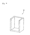
- the electrolytic cell 72 is formed by hollowing a fluoropolymer block so as to have the illustrated configuration of the electrolytic cell 72 having a handle 73 and a partition wall 76 and containing the electrolytic bath 3, as shown in FIG. 7.
- the electrolytic cell is integrally formed into the configuration as shown in FIG. 7.
- the electrolytic cell 72 has the configuration in which an opening is formed at the least one side surface.
- a transparent resin plate 75 of tetrafluoroethylene/perfluoroalkyl vinyl ether copolymer, trimethylpentene resin and equivalent is secured to the opening by threaded engagement of screws with a number of threaded holes formed in the opening, so as to hermetically seal up the electrolytic cell 72.
- a visual inspection of the interior of the electrolytic cell 72 can be made.
- a seal material of fluoropolymer is sandwiched between the body of the electrolytic cell 72 and the plate 75.
- a metal frame of stainless steel and the like corresponding in size to the plate 75 of the transparent resin comprising tetrafluoroethylene/perfluoroalkyl vinyl ether copolymer, trimethylpentene resin and equivalent is put on the seal material and then is screwed from the above.
- This can provide improved hermitical seal between the electrolytic cell 72 and the plate 75 of the transparent resin comprising tetrafluoroethylene/perfluoroalkyl vinyl ether copolymer, trimethylpentene resin and equivalent abutted with the side of the electrolytic cell 72.
- replacement of the electrodes 4, 6 and the mixed molten salt that turns into the electrolytic bath 3 can be facilitated.
- the electrolytic cell 72 is separated into the anode chamber 5 and the cathode chamber 7 by a partition wall 76 comprising the same resin as the electrolytic cell 72, and the electrodes comprising Ni are disposed in those chambers as the anode 4 and the cathode 6, respectively.
- the electrolytic cell 72 is provided, on its top surface, with the inlet and outlet ports 15, 17 for the purge gas from the pressure keeping means 50 via which the interior of the anode chamber 5 and the interior of the cathode chamber 17 are pressurized, the generation port 16 for the fluorine gas generated from the anode chamber 5, and the generation port 14 for the hydrogen gas generated from the cathode chamber 7.
- the electrolytic cell 72 is provided with the temperature control means for heating the interior of the electrolytic cell 72.
- the temperature control means comprises the heater 12 provided around the body of the electrolytic cell 72 so as to be in close contact with it, a temperature control (not shown) to make a general PID control which is connected to the heater 12, and the thermocouple 10 disposed in the cathode chamber 7.
- the temperature control means serves to make a temperature control of the interior of the electrolytic cell 2.
- the heat insulating material 77 is provided around the heater 12.
- the heater 12 may take any form, including a ribbon type one and a heating element, and no particular limitation is imposed on the form of the heater 12.
- the heater has, for example, a box-like form as shown in FIG. 8. This permits the electrolytic cell 72 to be housed in the box-like heater, and as such can permit precise temperature regulation of the interior of the electrolytic cell 72.
- Ni is used for both of the anode 4 and the cathode 6.
- the use of Ni for the anode 4 can prevent the production of CF 4 by reaction with carbon and fluorine gas, and as such can permit the production of high purity fluorine gas. In addition, this can also prevent the emergence of the anode effect that is a polarization phenomenon that is typical of the carbon electrode.
- the use of Ni for the cathode 6 can permit the surface energy to be reduced by hydride and oxide generated on the surface of Ni, as compared with the iron cathode. This permits the bubbles of the hydrogen gas generated to become so large that the mixture with the fluorine gas can be prevented.
- the mixture of the fluorine gas and the hydrogen gas can be suppressed further. This can permit the distance between the anode and the cathode to be reduced, and as such can permit the electrolytic cell to be reduced in size.
- the electrolytic cell 72 is formed by hollowing a fluoropolymer block so as to have the illustrated configuration of the electrolytic cell 72, first.
- the electrolytic cell 72 thus formed has the handle 73 and the electrolytic cell 72 having an opening at one side surface thereof and having the partition wall 76 at around a center portion thereof to separate the interior of the electrolytic cell 72 into two spaces, as shown in FIG. 7.
- the gas generation ports 14, 16 and the purge gas inlet and outlet ports 15, 17 are provided in the top portion of the electrolytic cell 72, and the Ni anode 4 and the Ni cathode 6 are attached to the top portion of the electrolytic cell 72.
- a pair of long-and-short level probes 8, 9 to detect the liquid level of the electrolytic bath are attached to the chambers 5, 7, respectively.
- the powdered KF • HF are filled in the electrolytic cell 72.
- a number of threaded holes 74 are formed in the side surface at the opening.
- the transparent resin plate 75 of tetrafluoroethylene/perfluoroalkyl vinyl ether copolymer, trimethylpentene resin and equivalent is threadedly engaged with the opening, with the seal material sandwiched therebetween.
- the thermocouple 10 for temperature regulation of the electrolytic bath 3 is attached to the cathode chamber 7. Thereafter, a prescribed amount of hydrogen fluoride anhydride is bubbled to prepare the electrolytic bath 3.
- the heater 12, the heat insulating material 77 and the gas lines such as the pressure keeping means 50 are disposed in place and accommodated in the cabinet.
- the interior of the electrolytic cell 72 is heated to approximately 90°C by the heater 12, with the result that the KF • 2HF mixed salt is melted so that it can be electrolyzed.
- the fluorine gas and the hydrogen gas produced by the electrolysis fill in the anode chamber 5 and the cathode chamber 7, then these gases being discharged from the gas generation ports 16, 14 by the gas introduced via the pressure keeping means 50 in such a fashion as to be extruded therefrom.
- the fluorine gas discharged from the anode chamber 5 is supplied in the form of high purity fluorine gas with the particles eliminated therefrom.
- the liquid levels of the electrolytic bath 3 in the anode chamber 5 and the cathode chamber 7 are detected by the level probes 8, 9.
- the solenoid valves 51, 52, 53, 54, 55, 56, 57, 58 are opened or closed accordingly, to control the liquid level in the electrolytic cell 72 so that it can be always within a certain level, as mentioned above. This can permit the stable electrolysis to proceed continuously, thus enabling the high purity fluorine gas to be supplied stably.
- the electrolytic bath 3 When the electrolytic bath 3 is electrolyzed for a long time, it is gradually suspended due to nickel fluoride (NiF 2 ) of the sludge generated at the electrolysis. This suspension can be visually inspected from the transparent plate 75 of the electrolytic cell 72. As accumulation of NiF 2 increases, resistance of the electrolytic bath 3 increases and it gradually becomes hard to proceed with the electrolysis. At that time, replacement of the electrolytic bath 3 is made. Also, when the Ni electrode is considerably consumed, the replacement of the electrode is made.
- NiF 2 nickel fluoride
- the high purity fluorine gas thus generated is controlled in pressure via the pressurization line 40 or the depressurization line 31 located downstream in the same manner as in FIG. 1, as shown in FIG. 7, and then is stored in the buffer tank 35 and the like.
- This enables a required amount of fluorine gas to be supplied from the supply ports 38, 49 as needed, and as such can allow the fluorine gas generating apparatus to be set in the semiconductor factory and the like on an on-site basis. This can permit the fluorine gas to be easily used for the cleaning of the semiconductor products and the like.
- the fluorine gas generating apparatus according to the present invention is so small in scale that it can be used on an on-site basis, the installation site and location is not limited.
- the apparatus of the present invention can be used for surface treatments of various types of materials as well as for production processes of semiconductors.
- the apparatus of the present invention can be applied to surface treatments of paper and textiles which are to be modified so as to provide water repellent property and hydrophilic property for them.
- the gas generating apparatus of the present invention can produce high purity fluorine gas stably. Also, the gas generating apparatus of the present invention can prevent leakage of electrolytic bath or solution from the electrolytic cell. Also, it can prevent leakage of fluorine gas produced. Further, since the gas generating apparatus of the present invention can provide the fluorine gas generating apparatus on an on-site basis, the need for the storage of the dangerous gas cylinder of fluorine gas can be eliminated, differently from the prior art. In view of these, the gas generating apparatus of the present invention can be used for surface treatments of various types of materials as well as for production fields of semiconductors.
Landscapes
- Chemical & Material Sciences (AREA)
- Engineering & Computer Science (AREA)
- Chemical Kinetics & Catalysis (AREA)
- Electrochemistry (AREA)
- Materials Engineering (AREA)
- Metallurgy (AREA)
- Organic Chemistry (AREA)
- Inorganic Chemistry (AREA)
- Automation & Control Theory (AREA)
- Electrolytic Production Of Non-Metals, Compounds, Apparatuses Therefor (AREA)
Applications Claiming Priority (5)
| Application Number | Priority Date | Filing Date | Title |
|---|---|---|---|
| JP2000111929 | 2000-04-07 | ||
| JP2000111929 | 2000-04-07 | ||
| JP2001074043 | 2001-03-15 | ||
| JP2001074043 | 2001-03-15 | ||
| PCT/JP2001/002976 WO2001077412A1 (fr) | 2000-04-07 | 2001-04-06 | Appareil pour la production de fluor gazeux |
Publications (2)
| Publication Number | Publication Date |
|---|---|
| EP1283280A1 true EP1283280A1 (fr) | 2003-02-12 |
| EP1283280A4 EP1283280A4 (fr) | 2004-09-15 |
Family
ID=26590032
Family Applications (1)
| Application Number | Title | Priority Date | Filing Date |
|---|---|---|---|
| EP01919801A Withdrawn EP1283280A4 (fr) | 2000-04-07 | 2001-04-06 | Appareil pour la production de fluor gazeux |
Country Status (6)
| Country | Link |
|---|---|
| US (1) | US6818105B2 (fr) |
| EP (1) | EP1283280A4 (fr) |
| KR (1) | KR100485490B1 (fr) |
| CN (1) | CN1307325C (fr) |
| TW (1) | TWI247051B (fr) |
| WO (1) | WO2001077412A1 (fr) |
Cited By (14)
| Publication number | Priority date | Publication date | Assignee | Title |
|---|---|---|---|---|
| EP1367149A1 (fr) * | 2002-05-29 | 2003-12-03 | Toyo Tanso Co., Ltd. | Générateur de fluor gazeux |
| WO2004009873A1 (fr) * | 2002-07-19 | 2004-01-29 | The Boc Group Plc | Dispositif et procede de production de fluor |
| EP1400612A1 (fr) * | 2002-09-20 | 2004-03-24 | Toyo Tanso Co., Ltd. | Générateur de fluor gazeux |
| WO2003056066A3 (fr) * | 2001-12-27 | 2004-03-25 | Air Liquide | Appareil de production et d'alimentation de gaz fluore |
| WO2004007802A3 (fr) * | 2002-07-11 | 2004-07-15 | Air Liquide | Appareil de production de gaz fluore |
| EP1455004A1 (fr) * | 2003-01-22 | 2004-09-08 | Toyo Tanso Co., Ltd. | Dispositif d'électrolyse de sels fondus. |
| EP1457587A1 (fr) * | 2002-11-08 | 2004-09-15 | Toyo Tanso Co., Ltd. | Générateur de fluor gazeux et procédé de contrôle du niveau d'électrolyte liquide |
| EP1498514A1 (fr) | 2003-07-14 | 2005-01-19 | Toyo Tanso Co., Ltd. | Dispositif et procédé de contrôle d'un bain de sel fondu électrolytique |
| WO2005031039A3 (fr) * | 2003-09-24 | 2005-06-16 | Air Liquide | Unite de production de fluor gazeux |
| EP1544325A2 (fr) | 2003-12-17 | 2005-06-22 | Toyo Tanso Co., Ltd. | Générateur de gaz |
| WO2006043125A1 (fr) * | 2004-10-20 | 2006-04-27 | L'air Liquide, Societe Anonyme A Directoire Et Conseil De Surveillance Pour L'etude Et L'exploitation Des Procedes Georges Claude | Generateur de gaz fluor |
| EP1422319A3 (fr) * | 2002-11-20 | 2011-08-10 | Toyo Tanso Kabushiki Kaisya | Générateur de fluor gazeux |
| US8945367B2 (en) | 2011-01-18 | 2015-02-03 | Air Products And Chemicals, Inc. | Electrolytic apparatus, system and method for the safe production of nitrogen trifluoride |
| EP2860287A1 (fr) * | 2013-10-11 | 2015-04-15 | Solvay SA | Cellule électrolytique améliorée |
Families Citing this family (23)
| Publication number | Priority date | Publication date | Assignee | Title |
|---|---|---|---|---|
| US20040151656A1 (en) * | 2001-11-26 | 2004-08-05 | Siegele Stephen H. | Modular molecular halogen gas generation system |
| AU2002349510A1 (en) * | 2001-12-17 | 2003-06-30 | Toyo Tanso Co., Ltd. | Apparatus for generating f2 gas and method for generating f2 gas, and f2 gas |
| JP3569277B1 (ja) * | 2003-05-28 | 2004-09-22 | 東洋炭素株式会社 | ガス発生装置の電流制御方法及び電流制御装置 |
| KR100641603B1 (ko) * | 2003-09-04 | 2006-11-02 | 주식회사 소디프신소재 | 고순도 불소의 제조방법 |
| JP4686157B2 (ja) * | 2004-09-29 | 2011-05-18 | 株式会社東芝 | 成膜装置のクリーニング方法 |
| JP4777989B2 (ja) * | 2005-08-25 | 2011-09-21 | 東洋炭素株式会社 | フッ素系ガス発生装置 |
| JP4717083B2 (ja) * | 2006-01-20 | 2011-07-06 | 東洋炭素株式会社 | フッ素又は三フッ化窒素を製造するための電解装置 |
| JP4018726B2 (ja) * | 2006-02-07 | 2007-12-05 | 東洋炭素株式会社 | 半導体製造プラント |
| EP2204233B1 (fr) * | 2007-08-31 | 2011-11-09 | Shimadzu Corporation | Cellule d'écoulement, appareil permettant la concentration d'anion fluor radioactif et procédé de concentration d'anion fluor radioactif |
| JP5659491B2 (ja) * | 2009-01-30 | 2015-01-28 | セントラル硝子株式会社 | フッ素ガス発生装置を含む半導体製造設備 |
| JP5438439B2 (ja) | 2009-09-04 | 2014-03-12 | 東洋炭素株式会社 | 気体供給システム |
| JP5581676B2 (ja) | 2009-12-02 | 2014-09-03 | セントラル硝子株式会社 | フッ素ガス生成装置 |
| TWI586842B (zh) * | 2010-09-15 | 2017-06-11 | 首威公司 | 氟之製造工廠及使用彼之方法 |
| TWI551730B (zh) * | 2010-11-17 | 2016-10-01 | 首威公司 | 電解器設備 |
| WO2013001800A1 (fr) * | 2011-06-29 | 2013-01-03 | 東洋炭素株式会社 | Dispositif d'électrolyse |
| JP5919824B2 (ja) * | 2012-01-05 | 2016-05-18 | セントラル硝子株式会社 | ガス生成装置 |
| US9382632B2 (en) | 2013-06-21 | 2016-07-05 | Savannah River Nuclear Solutions, Llc | Electrochemical fluorination for processing of used nuclear fuel |
| EP2919325B1 (fr) * | 2014-03-11 | 2017-02-22 | Nexans | Terminaison de câble électrique résistant à une forte conduction |
| US12188135B2 (en) | 2018-10-24 | 2025-01-07 | Resonac Corporation | Fluorine gas production device |
| CN110656344B (zh) * | 2019-11-05 | 2025-01-03 | 贵州理工学院 | 一种无水氟化氢除水的装置和方法 |
| CN111005032A (zh) * | 2019-12-26 | 2020-04-14 | 福建德尔科技有限公司 | 一种便携式全自动高纯氟气生产装置系统 |
| WO2021131578A1 (fr) * | 2019-12-27 | 2021-07-01 | 昭和電工株式会社 | Dispositif de production de gaz fluoré et détecteur à diffusion de lumière |
| CN111962093A (zh) * | 2020-07-06 | 2020-11-20 | 中船重工(邯郸)派瑞特种气体有限公司 | 一种电解制氟搅拌装置及方法 |
Family Cites Families (13)
| Publication number | Priority date | Publication date | Assignee | Title |
|---|---|---|---|---|
| JPS5825754B2 (ja) | 1980-03-11 | 1983-05-30 | 工業技術院長 | 耐振動性水電解装置 |
| US4511440A (en) * | 1983-12-22 | 1985-04-16 | Allied Corporation | Process for the electrolytic production of fluorine and novel cell therefor |
| JPH0757914B2 (ja) | 1986-11-21 | 1995-06-21 | 三井東圧化学株式会社 | 改良された電解槽 |
| JPH0678593B2 (ja) | 1989-03-03 | 1994-10-05 | 三井東圧化学株式会社 | 溶融塩電解法によるガスの製造方法 |
| JPH0353090A (ja) | 1989-07-18 | 1991-03-07 | Asahi Glass Co Ltd | フッ素の製造方法 |
| DE69018761T2 (de) * | 1989-10-26 | 1995-12-07 | Mitsui Toatsu Chemicals | Methode zur Herstellung von Stickstofftrifluorid. |
| CA2071235C (fr) * | 1991-07-26 | 2004-10-19 | Gerald L. Bauer | Anode pour cellule electrolytique utilisee pour la preparation du fluor |
| JPH0688267A (ja) | 1992-09-08 | 1994-03-29 | Mitsui Toatsu Chem Inc | 電解槽 |
| JP3485928B2 (ja) * | 1993-09-03 | 2004-01-13 | ミネソタ マイニング アンド マニュファクチャリング カンパニー | フッ素電解槽 |
| GB9418598D0 (en) * | 1994-09-14 | 1994-11-02 | British Nuclear Fuels Plc | Fluorine cell |
| JP3037121B2 (ja) * | 1995-11-20 | 2000-04-24 | 神鋼パンテツク株式会社 | 水素・酸素発生装置 |
| JP3037124B2 (ja) | 1995-12-21 | 2000-04-24 | 神鋼パンテツク株式会社 | 水素・酸素発生装置及びその運転方法 |
| JP2000313981A (ja) | 1999-04-27 | 2000-11-14 | Toyo Tanso Kk | フッ素電解用炭素電極 |
-
2001
- 2001-04-06 TW TW090108342A patent/TWI247051B/zh not_active IP Right Cessation
- 2001-04-06 CN CNB018076548A patent/CN1307325C/zh not_active Expired - Fee Related
- 2001-04-06 WO PCT/JP2001/002976 patent/WO2001077412A1/fr not_active Ceased
- 2001-04-06 EP EP01919801A patent/EP1283280A4/fr not_active Withdrawn
- 2001-04-06 US US10/240,722 patent/US6818105B2/en not_active Expired - Fee Related
- 2001-04-06 KR KR10-2002-7013140A patent/KR100485490B1/ko not_active Expired - Fee Related
Non-Patent Citations (2)
| Title |
|---|
| No further relevant documents disclosed * |
| See also references of WO0177412A1 * |
Cited By (20)
| Publication number | Priority date | Publication date | Assignee | Title |
|---|---|---|---|---|
| WO2003056066A3 (fr) * | 2001-12-27 | 2004-03-25 | Air Liquide | Appareil de production et d'alimentation de gaz fluore |
| EP1367149A1 (fr) * | 2002-05-29 | 2003-12-03 | Toyo Tanso Co., Ltd. | Générateur de fluor gazeux |
| US8038852B2 (en) | 2002-05-29 | 2011-10-18 | Toyo Tanso Co., Ltd. | Fluorine gas generator |
| WO2004007802A3 (fr) * | 2002-07-11 | 2004-07-15 | Air Liquide | Appareil de production de gaz fluore |
| WO2004009873A1 (fr) * | 2002-07-19 | 2004-01-29 | The Boc Group Plc | Dispositif et procede de production de fluor |
| EP1400612A1 (fr) * | 2002-09-20 | 2004-03-24 | Toyo Tanso Co., Ltd. | Générateur de fluor gazeux |
| US7351322B2 (en) | 2002-11-08 | 2008-04-01 | Toyo Tanso Co., Ltd. | Fluorine gas generator and method of electrolytic bath liquid level control |
| EP1457587A1 (fr) * | 2002-11-08 | 2004-09-15 | Toyo Tanso Co., Ltd. | Générateur de fluor gazeux et procédé de contrôle du niveau d'électrolyte liquide |
| EP1422319A3 (fr) * | 2002-11-20 | 2011-08-10 | Toyo Tanso Kabushiki Kaisya | Générateur de fluor gazeux |
| EP1455004A1 (fr) * | 2003-01-22 | 2004-09-08 | Toyo Tanso Co., Ltd. | Dispositif d'électrolyse de sels fondus. |
| US7316765B2 (en) | 2003-07-14 | 2008-01-08 | Toyo Tanso Co., Ltd. | Apparatus and method for molten salt electrolytic bath control |
| EP1498514A1 (fr) | 2003-07-14 | 2005-01-19 | Toyo Tanso Co., Ltd. | Dispositif et procédé de contrôle d'un bain de sel fondu électrolytique |
| WO2005031039A3 (fr) * | 2003-09-24 | 2005-06-16 | Air Liquide | Unite de production de fluor gazeux |
| EP1544325A3 (fr) * | 2003-12-17 | 2005-09-21 | Toyo Tanso Co., Ltd. | Générateur de gaz |
| EP1544325A2 (fr) | 2003-12-17 | 2005-06-22 | Toyo Tanso Co., Ltd. | Générateur de gaz |
| US7556678B2 (en) | 2003-12-17 | 2009-07-07 | Toyo Tanso Co., Ltd. | Gas generator |
| WO2006043125A1 (fr) * | 2004-10-20 | 2006-04-27 | L'air Liquide, Societe Anonyme A Directoire Et Conseil De Surveillance Pour L'etude Et L'exploitation Des Procedes Georges Claude | Generateur de gaz fluor |
| US8945367B2 (en) | 2011-01-18 | 2015-02-03 | Air Products And Chemicals, Inc. | Electrolytic apparatus, system and method for the safe production of nitrogen trifluoride |
| EP2860287A1 (fr) * | 2013-10-11 | 2015-04-15 | Solvay SA | Cellule électrolytique améliorée |
| WO2015052253A1 (fr) * | 2013-10-11 | 2015-04-16 | Solvay Sa | Cellule électrolytique améliorée |
Also Published As
| Publication number | Publication date |
|---|---|
| US6818105B2 (en) | 2004-11-16 |
| CN1307325C (zh) | 2007-03-28 |
| TWI247051B (en) | 2006-01-11 |
| WO2001077412A1 (fr) | 2001-10-18 |
| CN1441857A (zh) | 2003-09-10 |
| US20030047445A1 (en) | 2003-03-13 |
| KR20030019338A (ko) | 2003-03-06 |
| KR100485490B1 (ko) | 2005-04-28 |
| EP1283280A4 (fr) | 2004-09-15 |
Similar Documents
| Publication | Publication Date | Title |
|---|---|---|
| US6818105B2 (en) | Apparatus for generating fluorine gas | |
| JP3645495B2 (ja) | フッ素ガス発生装置 | |
| CN101213325B (zh) | 制造氟或三氟化氮的电解装置 | |
| KR100543647B1 (ko) | 불소가스 발생장치 | |
| KR100519843B1 (ko) | 불소가스 발생장치 | |
| US20130334059A1 (en) | Apparatus for electrolyzing sulfuric acid and method for electrolyzing sulfuric acid | |
| TW200918688A (en) | Apparatus for generating fluorine-based gas and hydrogen gas | |
| US20040055874A1 (en) | Fluorine gas generator | |
| CN115337803B (zh) | 全自动、安全型氟/惰性气体动态混合系统 | |
| US7351322B2 (en) | Fluorine gas generator and method of electrolytic bath liquid level control | |
| KR100579385B1 (ko) | 용융염 전해욕의 제어 장치와 그 제어 방법 | |
| JP4085174B2 (ja) | フッ素ガス発生装置 | |
| JP3553927B2 (ja) | フッ素ガス発生装置及びその電解浴液面制御方法 | |
| JP2009191362A (ja) | 溶融塩電解装置及びフッ素ガスの発生方法 | |
| CN115430302A (zh) | 用于氟/氮动态混合的氟气安全动态供给装置及方法 | |
| JP5881271B2 (ja) | 気体発生装置 | |
| JP2013091819A (ja) | 電解装置 |
Legal Events
| Date | Code | Title | Description |
|---|---|---|---|
| PUAI | Public reference made under article 153(3) epc to a published international application that has entered the european phase |
Free format text: ORIGINAL CODE: 0009012 |
|
| 17P | Request for examination filed |
Effective date: 20021106 |
|
| AK | Designated contracting states |
Designated state(s): AT BE CH CY DE DK ES FI FR GB GR IE IT LI LU MC NL PT SE TR |
|
| AX | Request for extension of the european patent |
Extension state: AL LT LV MK RO SI |
|
| RBV | Designated contracting states (corrected) |
Designated state(s): AT BE CH DE FR GB LI |
|
| A4 | Supplementary search report drawn up and despatched |
Effective date: 20040730 |
|
| 17Q | First examination report despatched |
Effective date: 20101014 |
|
| GRAP | Despatch of communication of intention to grant a patent |
Free format text: ORIGINAL CODE: EPIDOSNIGR1 |
|
| INTG | Intention to grant announced |
Effective date: 20160405 |
|
| RBV | Designated contracting states (corrected) |
Designated state(s): DE FR GB |
|
| RIN1 | Information on inventor provided before grant (corrected) |
Inventor name: TAKEBAYASHI, HITOSHI Inventor name: TOJO, TETSURO Inventor name: HIRAIWA, JIRO Inventor name: TADA, YOSHITOMI |
|
| STAA | Information on the status of an ep patent application or granted ep patent |
Free format text: STATUS: THE APPLICATION IS DEEMED TO BE WITHDRAWN |
|
| 18D | Application deemed to be withdrawn |
Effective date: 20160817 |