EP1302665A2 - Compresseur à gaz avec un séparateur d'huile - Google Patents
Compresseur à gaz avec un séparateur d'huile Download PDFInfo
- Publication number
- EP1302665A2 EP1302665A2 EP02256953A EP02256953A EP1302665A2 EP 1302665 A2 EP1302665 A2 EP 1302665A2 EP 02256953 A EP02256953 A EP 02256953A EP 02256953 A EP02256953 A EP 02256953A EP 1302665 A2 EP1302665 A2 EP 1302665A2
- Authority
- EP
- European Patent Office
- Prior art keywords
- oil separation
- separation filter
- filter
- end portion
- forward end
- Prior art date
- Legal status (The legal status is an assumption and is not a legal conclusion. Google has not performed a legal analysis and makes no representation as to the accuracy of the status listed.)
- Granted
Links
Images


Classifications
-
- F—MECHANICAL ENGINEERING; LIGHTING; HEATING; WEAPONS; BLASTING
- F04—POSITIVE - DISPLACEMENT MACHINES FOR LIQUIDS; PUMPS FOR LIQUIDS OR ELASTIC FLUIDS
- F04C—ROTARY-PISTON, OR OSCILLATING-PISTON, POSITIVE-DISPLACEMENT MACHINES FOR LIQUIDS; ROTARY-PISTON, OR OSCILLATING-PISTON, POSITIVE-DISPLACEMENT PUMPS
- F04C29/00—Component parts, details or accessories of pumps or pumping installations, not provided for in groups F04C18/00 - F04C28/00
- F04C29/02—Lubrication; Lubricant separation
- F04C29/026—Lubricant separation
-
- F—MECHANICAL ENGINEERING; LIGHTING; HEATING; WEAPONS; BLASTING
- F01—MACHINES OR ENGINES IN GENERAL; ENGINE PLANTS IN GENERAL; STEAM ENGINES
- F01C—ROTARY-PISTON OR OSCILLATING-PISTON MACHINES OR ENGINES
- F01C21/00—Component parts, details or accessories not provided for in groups F01C1/00 - F01C20/00
- F01C21/10—Outer members for co-operation with rotary pistons; Casings
- F01C21/104—Stators; Members defining the outer boundaries of the working chamber
-
- F—MECHANICAL ENGINEERING; LIGHTING; HEATING; WEAPONS; BLASTING
- F04—POSITIVE - DISPLACEMENT MACHINES FOR LIQUIDS; PUMPS FOR LIQUIDS OR ELASTIC FLUIDS
- F04C—ROTARY-PISTON, OR OSCILLATING-PISTON, POSITIVE-DISPLACEMENT MACHINES FOR LIQUIDS; ROTARY-PISTON, OR OSCILLATING-PISTON, POSITIVE-DISPLACEMENT PUMPS
- F04C18/00—Rotary-piston pumps specially adapted for elastic fluids
- F04C18/30—Rotary-piston pumps specially adapted for elastic fluids having the characteristics covered by two or more of groups F04C18/02, F04C18/08, F04C18/22, F04C18/24, F04C18/48, or having the characteristics covered by one of these groups together with some other type of movement between co-operating members
- F04C18/34—Rotary-piston pumps specially adapted for elastic fluids having the characteristics covered by two or more of groups F04C18/02, F04C18/08, F04C18/22, F04C18/24, F04C18/48, or having the characteristics covered by one of these groups together with some other type of movement between co-operating members having the movement defined in group F04C18/08 or F04C18/22 and relative reciprocation between the co-operating members
- F04C18/344—Rotary-piston pumps specially adapted for elastic fluids having the characteristics covered by two or more of groups F04C18/02, F04C18/08, F04C18/22, F04C18/24, F04C18/48, or having the characteristics covered by one of these groups together with some other type of movement between co-operating members having the movement defined in group F04C18/08 or F04C18/22 and relative reciprocation between the co-operating members with vanes reciprocating with respect to the inner member
- F04C18/3446—Rotary-piston pumps specially adapted for elastic fluids having the characteristics covered by two or more of groups F04C18/02, F04C18/08, F04C18/22, F04C18/24, F04C18/48, or having the characteristics covered by one of these groups together with some other type of movement between co-operating members having the movement defined in group F04C18/08 or F04C18/22 and relative reciprocation between the co-operating members with vanes reciprocating with respect to the inner member the inner and outer member being in contact along more than one line or surface
-
- Y—GENERAL TAGGING OF NEW TECHNOLOGICAL DEVELOPMENTS; GENERAL TAGGING OF CROSS-SECTIONAL TECHNOLOGIES SPANNING OVER SEVERAL SECTIONS OF THE IPC; TECHNICAL SUBJECTS COVERED BY FORMER USPC CROSS-REFERENCE ART COLLECTIONS [XRACs] AND DIGESTS
- Y10—TECHNICAL SUBJECTS COVERED BY FORMER USPC
- Y10S—TECHNICAL SUBJECTS COVERED BY FORMER USPC CROSS-REFERENCE ART COLLECTIONS [XRACs] AND DIGESTS
- Y10S418/00—Rotary expansible chamber devices
- Y10S418/01—Non-working fluid separation
-
- Y—GENERAL TAGGING OF NEW TECHNOLOGICAL DEVELOPMENTS; GENERAL TAGGING OF CROSS-SECTIONAL TECHNOLOGIES SPANNING OVER SEVERAL SECTIONS OF THE IPC; TECHNICAL SUBJECTS COVERED BY FORMER USPC CROSS-REFERENCE ART COLLECTIONS [XRACs] AND DIGESTS
- Y10—TECHNICAL SUBJECTS COVERED BY FORMER USPC
- Y10S—TECHNICAL SUBJECTS COVERED BY FORMER USPC CROSS-REFERENCE ART COLLECTIONS [XRACs] AND DIGESTS
- Y10S55/00—Gas separation
- Y10S55/17—Compressed air water removal
Definitions
- the present invention relates to a gas compressor for use in a vehicle air conditioning system or the like and, more particularly, aims to prevent fretting wear due to vibration of an oil separation filter contained in an apparatus to thereby achieve an improvement in durability.
- a gas compressor of this type has, as shown, for example, in Fig. 7, a compression mechanism C in a compressor case 1, and this compression mechanism C sucks in low pressure refrigerant gas in a suction chamber 6 and compresses it before discharging it into a discharge chamber 5 as high pressure refrigerant gas.
- the high pressure refrigerant immediately after being discharged from the compression mechanism C contains oil in the mist state filled for the purpose, for example, of lubricating the sliding portion of the compression mechanism portion C, and the oil ingredient in such high pressure refrigerant gas is separated by an oil separator 20 contained in the gas compressor.
- the oil separator 20 has an oil separation filter 21 formed by rolling a wire net into a cylinder, and the oil ingredient in the high pressure refrigerant gas is separated when a high speed gas flow of high pressure refrigerant gas strikes upon the wire net constituting the oil separation filter 21 or by the centrifugal force generated when high pressure refrigerant gas whirls inside the oil separation filter 21.
- the present invention has been made in view of the above problem. It is an object of the present invention to provide a gas compressor in which fretting wear due to vibration of the oil separation filter is prevented to thereby achieve an improvement in durability.
- a gas compressor characterized by comprising a compression mechanism portion which sucks in, compresses, and discharges refrigerant gas, a discharge chamber for temporarily storing the refrigerant gas discharged from the compression mechanism portion, a discharge passage which causes the compression mechanism portion to communicate with the discharge chamber and which guides the refrigerant gas discharged from the compression mechanism portion to the discharge chamber, an oil separation filter which is arranged in the discharge chamber and at the downstream end of the discharge passage and which is formed by shaping a lattice-like member into a cylindrical configuration, a press-fixing means for press-fixing the end portions of the oil separation filter, and an oil sump formed at the bottom of the discharge chamber and adapted to store the oil separated by the oil separation filter.
- the oil separation filter as a whole is firmly fixed by the press-fixing force when the press-fixing means press-fixes the end portions of the oil separation filter.
- the press-fixing means it is possible to adopt a construction comprising an abutment block portion against which the bottom end portion of the oil separation filter abuts, an outer peripheral block portion having a filter accommodating hole into which the oil separation filter is inserted, and a pressurizing plate put over the forward end portion of the oil separation filter and mounted and fixed to the outer peripheral block portion, wherein the forward end portion of the oil separation filter is provided so as to protrude from the filter accommodating hole on the surface of the outer peripheral block portion, and wherein the protruding forward end portion of the oil separation filter is pressurized and bent by the pressurizing plate to undergo elastic deformation.
- the forward end portion of the oil separation filter is pressurized and bent toward the abutment block portion by the pressurizing plate to undergo elastic deformation, and due to this elastic deformation of the oil separation filter, the oil separation filter is strongly pressed against the pressurizing plate, the abutment block, and the outer peripheral block portion and fixed thereto.
- the forward end portion of the oil separation filter is press-bent by the pressurizing plate such that all the portions thereof are directed in the same direction, so that the construction proves superior in operability in fixing the bending direction.
- the direction in which the forward end portion of the oil separation filter is previously bent be toward the inner side of the filter.
- the forward end portion of the oil separation filter is press-bent by the pressurizing plate such that it is always directed to the inner side of the filter, so that there is no danger of the bent forward end portion of the oil separation filter being caught between the pressurizing plate and the outer peripheral block, making it possible to correctly mount and fix the pressurizing plate to the outer peripheral block portion.
- the oil separation filter may, for example, be formed of a lattice-like member, such as wire net or expanded metal; in particular, in the case of a wire net type oil separation filter, it is desirable to fuse by spot welding the regions where the constituent wire materials of the wire net (wires) intersect each other in order to prevent fretting wear as a result of the constituent wires of the wire net being rubbed against each other.
- a lattice-like member such as wire net or expanded metal
- the spot welding is performed in order to prevent fretting wear mainly due to vibration between the constituent wire materials of the wire net, and, from the viewpoint of the object of this spot welding, it is desirable to increase the number of spot welding points for the region where, for example, the high speed gas flow of high pressure refrigerant gas first strikes directly.
- the gas compressor of this embodiment has a construction in which a compression mechanism portion C is accommodated in a one-end-open-type compressor case 1, and, between this compression mechanism portion C and a front head 1-2 mounted to the open end of the compressor case 1, there is defined a low pressure suction chamber 6 (low pressure chamber); further, between the inner, closed end of the compressor case 1 and the compression mechanism portion C, there is formed a high pressure discharge chamber 5 (high pressure chamber).
- a low pressure suction chamber 6 low pressure chamber
- high pressure discharge chamber 5 high pressure chamber
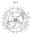
- the compression mechanism portion C has a cylinder 2 with a substantially elliptical inner periphery, and side blocks 3 and 4 are mounted to the end surfaces of the cylinder 2; further, inside the cylinder 2, a rotor 7 is horizontally installed, and the rotor 7 is supported so as to be rotatable through the intermediation of a rotor shaft 8 at the axial center thereof, a bearing 9 of the front side block 3, and a bearing (not shown) of the rear side block 4.
- each vane 12 is slidably arranged, each vane 12 being provided so as to be retractable from the outer peripheral surface of the rotor 7 toward the inner peripheral surface of the cylinder 2.
- the inner space of the cylinder 2 is divided into a plurality of small chambers by the inner wall of the cylinder 2, the inner surfaces of the side blocks 3 and 4, the outer peripheral surface of the rotor 7, and the side surfaces of the forward end portions of the vanes 12, and the small chambers thus formed are compression chambers 13; the compression chambers 13 rotate in the direction of the arrow in Fig. 8 to thereby continuously undergo variation in volume, and, through this variation in volume, they suck in and compress the refrigerant gas in the suction chamber 6 and discharge it to the discharge chamber 5 side.
- the volume of the compression chambers 13 increases, the low pressure refrigerant gas in the suction chamber 6 is sucked in by the compression chambers 13 through suction passages 14 of the cylinder 2, etc. and suction holes 15 of the side blocks 3 and 4 . Then, when the volume of the compression chambers 13 starts to be reduced, the refrigerant gas in the compression chambers 13 is compressed due to the volume reduction effect.
- reed valves 17a of cylinder discharge holes 16 provided near the ellipsoid shorter-diameter portion of the cylinder are opened by the pressure of the compressed high pressure refrigerant gas, whereby the high pressure refrigerant gas in the compression chambers 13 passes through the cylinder discharge holes 16, discharge chambers 18 in the cylinder outer space, and a high pressure gas passage 19 before it is discharged to the discharge chamber 5 side and is temporarily stored in this discharge chamber 5.
- a series of passages consisting of the cylinder discharge holes 16, the discharge chambers 18 in the cylinder outer space, the high pressure gas passage 19, etc. establish communication between the compression mechanism portion C and the discharge chamber 5, and constitutes a discharge passage for guiding the refrigerant gas discharged from the compression chambers 13 of the compression mechanism portion C to the discharge chamber 5; an oil separator 20 is provided at the downstream end of this discharge passage.
- the oil separator 20 is composed of an oil separation filter 21, an abutment block portion 22, an outer peripheral block portion 23, a pressurizing plate 25, etc.
- the oil separation filter 21 is arranged at the downstream end of such a discharge passage in the discharge chamber 5, and is of a wire net type using as the lattice-like member a wire net, which is spirally rolled into a cylinder.
- this oil separation filter 21 is attached to a filter accommodating hole 26 of the outer peripheral block portion 23, and its end portions are press-fixed by the abutment block portion 22 and the pressurizing plate 25.
- the outer peripheral block portion 23 has a filter accommodating hole 26 whose diameter is somewhat larger than that of the oil separation filter 21 (See Fig. 2), and the oil separation filter 21 is inserted into this filter accommodating hole 26 and secured therein; further, the abutment block portion 22 is formed such that the bottom end portion of the inserted oil separation filter 21 abuts it.
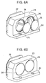
- the oil separation filter 21 is inserted into the filter accommodating hole 26 of the outer peripheral block portion 23 as described above, and when the bottom end portion of this oil separation filter 21 abuts the abutment block portion 22, the forward end portion 21a of the oil separation filter 21 protrudes from the filter accommodating hole 26 somewhat beyond the surface 23a of the outer peripheral block portion 23 as shown in Fig. 1A.
- the entire longitudinal length L1 of the oil separation filter 21 is somewhat larger than the depth (filter accommodation depth) L2 as measured from the filter abutment surface 22a of the abutment block portion 22 against which the bottom portion of the oil separation filter 21 abuts to the inlet 26a of the filter accommodating hole 26.
- the forward end portion 21a of the oil separation filter 21, which protrudes as described above, is press-bent by the pressurizing plate 25 as the press-bending/crushing margin as shown in Fig. 1B, whereby, between the pressurizing plate 25 and the abutment block portion 22, the pressurizing plate 25 and the abutment block portion 22 press-fix the end portions of the oil separation filter 21.
- the pressurizing plate 25 mounted and fixed to the outer peripheral block portion 23 by means of bolts 25-1 is put over the oil separation filter forward end portion 21a; due to the fastening force when fastening the pressurizing plate 25 to the outer peripheral block portion 23 by means of the bolts 25-1, a force press-bending the oil separation filter forward end portion 21a is generated in the pressurizing plate 25. Then, due to this press-bending force, the oil separation filter forward end portion 21a is pressed against the abutment block portion 22 and undergoes elastic deformation and plastic deformation to be press-bent as shown in Fig. 1B.
- the oil separation filter 21 is clamped so as to be strongly pressed against and fixed to the pressurizing plate 25; the abutment block portion 22, and the outer peripheral block portion 23.
- this embodiment adopts an arrangement in which the oil separation filter 21 undergoes not only elastic deformation but also plastic deformation. This is due to the fact that an elastic deformation involving plastic deformation allows the elastic force to be exerted to the utmost.
- the oil separation filter 21 of a material with high Young's modulus and appropriately setting the crushing margin of the oil separation filter 21, it is also possible to achieve an equivalent elastic force solely through elastic deformation involving no plastic deformation.
- the abutment block portion 22 and the outer peripheral block portion 23 are provided integrally through the intermediation of a base block portion 24, and are mounted and fixed to the rear side block constituting the wall surface of the discharge chamber 5.
- a communication passage (not shown) establishing communicating connection between the high pressure gas passage 19 (See Fig. 7) and the filter accommodating hole 26, and high pressure refrigerant gas is introduced from the high pressure gas passage 19 to the oil separation filter 21 side through this communication passage (not shown) .
- the high pressure refrigerant gas thus introduced strikes against the wire net constituting the oil separation filter 21, and whirls circumferentially inside the oil separation filter 21.
- oil is contained as a mist in the high pressure refrigerant gas immediately after its discharge from the compression mechanism portion C; due to the striking of the high pressure refrigerant gas against the oil separation filter 21 and the centrifugal force generated by the whirling of the high pressure refrigerant gas inside the oil separation filter 21, the oil ingredient in the high pressure refrigerant gas is separated, and drips into the oil sump 28 at the bottom of the discharge chamber 5 to be stored there.
- the oil separation filter forward end portion 21a In order to prevent the oil separation filter forward end portion 21a from thus sticking out, it is desirable, as shown in Fig. 3, for the oil separation filter forward end portion 21a to be bent previously and positively in a fixed direction, more specifically, toward the filter inner side, before being press-bent by the pressurizing plate 25.
- the pre-bending amount of the oil separation filter forward end portion 21a is less than the amount by which the oil separation filter forward end portion 21a is press-bent by the pressurizing plate 25 because if the latter is larger than that, the press-bending of the oil separation filter forward end portion 21a by the pressurizing plate 25 is impossible, and the above effect of this press-bending, that is, the effect of firmly fixing the oil separation filter 21 through elastic deformation, cannot be obtained.
- a sticking-out preventing structure as shown in Fig. 4.
- a clearance groove 27 is annularly formed in the inner peripheral surface of the filter accommodating hole 26. In the case of this structure, when the oil separation filter forward end portion 21a is press-bent on the filter outer side, the press-bent portion enters this clearance groove 27.
- the sticking-out preventing structure of Fig. 4 makes it possible to effectively prevent the bent oil separation filter forward end portion 21a from sticking out and getting caught between the pressurizing plate 25 and the outer peripheral block portion 23, making it possible to mount and fix the pressurizing plate 25 to the outer peripheral block portion 23 correctly.
- the wire net type oil separation filter 21 is adopted; when using this wire net type oil separation filter 21, it is desirable to perform spot welding for fusing connection on the regions where the constituent wire materials (wires) of the wire net intersect each other, as shown in Fig. 5.
- This spot welding is performed for the purpose of preventing fretting wear mainly due to vibration between the constituent wire materials of the wire net.
- the oil separation filter forward end portion 21a is press-bent by the fastening force when fastening the pressurizing plate 25 to the outer peripheral block portion 23 by means of the bolts 25-1; instead, it is also possible, as shown in Fig. 6, to fix the pressurizing plates 25 to the filter accommodating holes 26 of the outer peripheral block portion 23 by caulking, and to press-bent the oil separation filter forward end portion 21a by the caulking force.
- the lattice-like member constituting the oil separation filter 21 may also consist, for example, of expanded metal; in the case of expanded metal, a thin plate with fine alternate slits is expanded into a lattice-like form like a wire net; the oil separation filter 21 may be formed by shaping this expanded metal into a cylinder.
- a press-fixing means for press-fixing the end portions of the oil separation filter, and the entire oil separation filter is firmly fixed by the press-fixing force when the press-fixing means press-fixes the end portions of the oil separation filter.
Landscapes
- Engineering & Computer Science (AREA)
- Mechanical Engineering (AREA)
- General Engineering & Computer Science (AREA)
- Compressor (AREA)
- Applications Or Details Of Rotary Compressors (AREA)
- Rotary Pumps (AREA)
Applications Claiming Priority (2)
| Application Number | Priority Date | Filing Date | Title |
|---|---|---|---|
| JP2001316887A JP4088056B2 (ja) | 2001-10-15 | 2001-10-15 | 気体圧縮機 |
| JP2001316887 | 2001-10-15 |
Publications (3)
| Publication Number | Publication Date |
|---|---|
| EP1302665A2 true EP1302665A2 (fr) | 2003-04-16 |
| EP1302665A3 EP1302665A3 (fr) | 2003-08-06 |
| EP1302665B1 EP1302665B1 (fr) | 2005-03-02 |
Family
ID=19134833
Family Applications (1)
| Application Number | Title | Priority Date | Filing Date |
|---|---|---|---|
| EP02256953A Expired - Lifetime EP1302665B1 (fr) | 2001-10-15 | 2002-10-08 | Compresseur à gaz avec un séparateur d'huile |
Country Status (6)
| Country | Link |
|---|---|
| US (1) | US6736623B2 (fr) |
| EP (1) | EP1302665B1 (fr) |
| JP (1) | JP4088056B2 (fr) |
| CN (1) | CN100402862C (fr) |
| DE (1) | DE60203080T2 (fr) |
| MY (1) | MY124863A (fr) |
Families Citing this family (5)
| Publication number | Priority date | Publication date | Assignee | Title |
|---|---|---|---|---|
| KR950005269B1 (ko) * | 1992-07-29 | 1995-05-22 | 삼성전자주식회사 | 반도체 패키지 구조 및 제조방법 |
| US7520210B2 (en) | 2006-09-27 | 2009-04-21 | Visteon Global Technologies, Inc. | Oil separator for a fluid displacement apparatus |
| US11054178B2 (en) | 2017-11-15 | 2021-07-06 | Vilter Manufacturing Llc | Crankcase oil separation for high pressure reciprocating compressors |
| US20200102943A1 (en) | 2018-10-02 | 2020-04-02 | Vilter Manufacturing Llc | 3D-Printed Oil Separation for Reciprocating Compressors |
| CN116978669B (zh) * | 2023-08-03 | 2024-10-11 | 西安西电变压器有限责任公司 | 变压器压梁结构、变压器使用预弯压梁数量的计算方法 |
Family Cites Families (14)
| Publication number | Priority date | Publication date | Assignee | Title |
|---|---|---|---|---|
| US1892210A (en) * | 1930-05-20 | 1932-12-27 | John A Gordon | Filter |
| US3385513A (en) * | 1966-04-11 | 1968-05-28 | Trw Inc | Refrigerant vapor compressor |
| US4091638A (en) * | 1976-12-13 | 1978-05-30 | Borg-Warner Corporation | Cooling system for hermetic compressor |
| JPS55101782A (en) * | 1979-01-26 | 1980-08-04 | Seiko Instr & Electronics Ltd | Oil separator in gas compressor |
| JPS55139288U (fr) * | 1979-03-26 | 1980-10-04 | ||
| JPS6084714U (ja) * | 1983-11-16 | 1985-06-11 | 日産自動車株式会社 | ミストセパレータ |
| US4516994A (en) * | 1984-04-11 | 1985-05-14 | Vilter Manufacturing Corporation | Apparatus for separating liquid droplets from gas |
| JPH07111183B2 (ja) * | 1988-09-28 | 1995-11-29 | ダイキン工業株式会社 | スクロール圧縮機 |
| JPH0726614B2 (ja) * | 1989-04-20 | 1995-03-29 | 三洋電機株式会社 | 空気供給装置 |
| JPH05177288A (ja) * | 1991-12-26 | 1993-07-20 | Hitachi Cable Ltd | 溶接金網の製造方法 |
| JPH0968179A (ja) * | 1995-08-31 | 1997-03-11 | Seiko Seiki Co Ltd | 気体圧縮機 |
| JP3671552B2 (ja) * | 1996-09-30 | 2005-07-13 | ダイキン工業株式会社 | 圧縮機用油分離器およびその製造方法 |
| JP3390120B2 (ja) * | 1996-12-16 | 2003-03-24 | 株式会社神戸製鋼所 | 油冷式圧縮機用油分離器 |
| US6261333B1 (en) * | 1999-07-09 | 2001-07-17 | Diesel Research, Inc. | Air filter for an internal combustion engine having a primary air region and a secondary air region |
-
2001
- 2001-10-15 JP JP2001316887A patent/JP4088056B2/ja not_active Expired - Fee Related
-
2002
- 2002-10-07 MY MYPI20023734A patent/MY124863A/en unknown
- 2002-10-08 DE DE60203080T patent/DE60203080T2/de not_active Expired - Lifetime
- 2002-10-08 EP EP02256953A patent/EP1302665B1/fr not_active Expired - Lifetime
- 2002-10-09 US US10/267,367 patent/US6736623B2/en not_active Expired - Lifetime
- 2002-10-15 CN CNB021558051A patent/CN100402862C/zh not_active Expired - Fee Related
Also Published As
| Publication number | Publication date |
|---|---|
| US20030095885A1 (en) | 2003-05-22 |
| EP1302665A3 (fr) | 2003-08-06 |
| US6736623B2 (en) | 2004-05-18 |
| JP4088056B2 (ja) | 2008-05-21 |
| JP2003120564A (ja) | 2003-04-23 |
| DE60203080T2 (de) | 2005-07-21 |
| DE60203080D1 (de) | 2005-04-07 |
| EP1302665B1 (fr) | 2005-03-02 |
| MY124863A (en) | 2006-07-31 |
| CN100402862C (zh) | 2008-07-16 |
| CN1414247A (zh) | 2003-04-30 |
Similar Documents
| Publication | Publication Date | Title |
|---|---|---|
| US6227831B1 (en) | Compressor having an inclined surface to guide lubricant oil | |
| JP3085949B2 (ja) | 背圧チャンバ内におけるシールの潤滑を行うスクロールコンプレッサ | |
| JP3199694B2 (ja) | 密閉型回転圧縮機の吐出マフラー | |
| JP4230785B2 (ja) | 気体圧縮機 | |
| JP5429353B1 (ja) | 圧縮機 | |
| US20130259725A1 (en) | Rotary compressor | |
| EP1302665B1 (fr) | Compresseur à gaz avec un séparateur d'huile | |
| KR20170110428A (ko) | 압축기 | |
| JP2003013858A (ja) | 圧縮機 | |
| US20100166586A1 (en) | Hermetic compressor | |
| JPH11247761A (ja) | 密閉形圧縮機 | |
| JP2002257055A (ja) | スクロール圧縮機 | |
| JP2001082337A (ja) | 圧縮機の吐出弁装置 | |
| JP3062815B1 (ja) | 気体圧縮機 | |
| JP2000213483A (ja) | ロ―タリ圧縮機 | |
| EP1217215A2 (fr) | Compresseur à gaz | |
| KR20070061952A (ko) | 스크롤 압축기 | |
| JPH11315793A (ja) | ロータリコンプレッサ | |
| KR100360864B1 (ko) | 밀폐형 회전식 압축기의 유토출 저감구조 | |
| JPH07293475A (ja) | 気体圧縮機 | |
| JP4524202B2 (ja) | 開放型スクロール圧縮機 | |
| JP3586693B2 (ja) | 気体圧縮機 | |
| JP2556947B2 (ja) | 密閉型電動圧縮機の油分離装置 | |
| JPH079053A (ja) | 回転式確動変位機、回転式確動変位機用シリンダおよびその製造方法 | |
| JPH05306692A (ja) | 圧縮機 |
Legal Events
| Date | Code | Title | Description |
|---|---|---|---|
| PUAI | Public reference made under article 153(3) epc to a published international application that has entered the european phase |
Free format text: ORIGINAL CODE: 0009012 |
|
| AK | Designated contracting states |
Designated state(s): AT BE BG CH CY CZ DE DK EE ES FI FR GB GR IE IT LI LU MC NL PT SE SK TR |
|
| AX | Request for extension of the european patent |
Extension state: AL LT LV MK RO SI |
|
| PUAL | Search report despatched |
Free format text: ORIGINAL CODE: 0009013 |
|
| AK | Designated contracting states |
Designated state(s): AT BE BG CH CY CZ DE DK EE ES FI FR GB GR IE IT LI LU MC NL PT SE SK TR |
|
| AX | Request for extension of the european patent |
Extension state: AL LT LV MK RO SI |
|
| 17P | Request for examination filed |
Effective date: 20031202 |
|
| 17Q | First examination report despatched |
Effective date: 20040219 |
|
| AKX | Designation fees paid |
Designated state(s): DE FR GB |
|
| GRAP | Despatch of communication of intention to grant a patent |
Free format text: ORIGINAL CODE: EPIDOSNIGR1 |
|
| RAP1 | Party data changed (applicant data changed or rights of an application transferred) |
Owner name: CALSONIC COMPRESSOR MANUFACTURING INC. |
|
| GRAS | Grant fee paid |
Free format text: ORIGINAL CODE: EPIDOSNIGR3 |
|
| GRAA | (expected) grant |
Free format text: ORIGINAL CODE: 0009210 |
|
| AK | Designated contracting states |
Kind code of ref document: B1 Designated state(s): DE FR GB |
|
| REG | Reference to a national code |
Ref country code: GB Ref legal event code: FG4D |
|
| REG | Reference to a national code |
Ref country code: IE Ref legal event code: FG4D |
|
| REF | Corresponds to: |
Ref document number: 60203080 Country of ref document: DE Date of ref document: 20050407 Kind code of ref document: P |
|
| ET | Fr: translation filed | ||
| PLBE | No opposition filed within time limit |
Free format text: ORIGINAL CODE: 0009261 |
|
| STAA | Information on the status of an ep patent application or granted ep patent |
Free format text: STATUS: NO OPPOSITION FILED WITHIN TIME LIMIT |
|
| 26N | No opposition filed |
Effective date: 20051205 |
|
| REG | Reference to a national code |
Ref country code: FR Ref legal event code: PLFP Year of fee payment: 14 |
|
| PGFP | Annual fee paid to national office [announced via postgrant information from national office to epo] |
Ref country code: FR Payment date: 20150908 Year of fee payment: 14 |
|
| PGFP | Annual fee paid to national office [announced via postgrant information from national office to epo] |
Ref country code: DE Payment date: 20150929 Year of fee payment: 14 Ref country code: GB Payment date: 20151007 Year of fee payment: 14 |
|
| REG | Reference to a national code |
Ref country code: DE Ref legal event code: R119 Ref document number: 60203080 Country of ref document: DE |
|
| GBPC | Gb: european patent ceased through non-payment of renewal fee |
Effective date: 20161008 |
|
| REG | Reference to a national code |
Ref country code: FR Ref legal event code: ST Effective date: 20170630 |
|
| PG25 | Lapsed in a contracting state [announced via postgrant information from national office to epo] |
Ref country code: DE Free format text: LAPSE BECAUSE OF NON-PAYMENT OF DUE FEES Effective date: 20170503 Ref country code: GB Free format text: LAPSE BECAUSE OF NON-PAYMENT OF DUE FEES Effective date: 20161008 Ref country code: FR Free format text: LAPSE BECAUSE OF NON-PAYMENT OF DUE FEES Effective date: 20161102 |