EP1312829A1 - Hydraulische schwingungsisolationsvorrichtung - Google Patents
Hydraulische schwingungsisolationsvorrichtung Download PDFInfo
- Publication number
- EP1312829A1 EP1312829A1 EP01984524A EP01984524A EP1312829A1 EP 1312829 A1 EP1312829 A1 EP 1312829A1 EP 01984524 A EP01984524 A EP 01984524A EP 01984524 A EP01984524 A EP 01984524A EP 1312829 A1 EP1312829 A1 EP 1312829A1
- Authority
- EP
- European Patent Office
- Prior art keywords
- orifice
- sub
- liquid chamber
- liquid
- vibration isolating
- Prior art date
- Legal status (The legal status is an assumption and is not a legal conclusion. Google has not performed a legal analysis and makes no representation as to the accuracy of the status listed.)
- Withdrawn
Links
Images


Classifications
-
- F—MECHANICAL ENGINEERING; LIGHTING; HEATING; WEAPONS; BLASTING
- F16—ENGINEERING ELEMENTS AND UNITS; GENERAL MEASURES FOR PRODUCING AND MAINTAINING EFFECTIVE FUNCTIONING OF MACHINES OR INSTALLATIONS; THERMAL INSULATION IN GENERAL
- F16F—SPRINGS; SHOCK-ABSORBERS; MEANS FOR DAMPING VIBRATION
- F16F13/00—Units comprising springs of the non-fluid type as well as vibration-dampers, shock-absorbers, or fluid springs
- F16F13/04—Units comprising springs of the non-fluid type as well as vibration-dampers, shock-absorbers, or fluid springs comprising both a plastics spring and a damper, e.g. a friction damper
- F16F13/06—Units comprising springs of the non-fluid type as well as vibration-dampers, shock-absorbers, or fluid springs comprising both a plastics spring and a damper, e.g. a friction damper the damper being a fluid damper, e.g. the plastics spring not forming a part of the wall of the fluid chamber of the damper
- F16F13/08—Units comprising springs of the non-fluid type as well as vibration-dampers, shock-absorbers, or fluid springs comprising both a plastics spring and a damper, e.g. a friction damper the damper being a fluid damper, e.g. the plastics spring not forming a part of the wall of the fluid chamber of the damper the plastics spring forming at least a part of the wall of the fluid chamber of the damper
- F16F13/10—Units comprising springs of the non-fluid type as well as vibration-dampers, shock-absorbers, or fluid springs comprising both a plastics spring and a damper, e.g. a friction damper the damper being a fluid damper, e.g. the plastics spring not forming a part of the wall of the fluid chamber of the damper the plastics spring forming at least a part of the wall of the fluid chamber of the damper the wall being at least in part formed by a flexible membrane or the like
- F16F13/105—Units comprising springs of the non-fluid type as well as vibration-dampers, shock-absorbers, or fluid springs comprising both a plastics spring and a damper, e.g. a friction damper the damper being a fluid damper, e.g. the plastics spring not forming a part of the wall of the fluid chamber of the damper the plastics spring forming at least a part of the wall of the fluid chamber of the damper the wall being at least in part formed by a flexible membrane or the like characterised by features of partitions between two working chambers
-
- F—MECHANICAL ENGINEERING; LIGHTING; HEATING; WEAPONS; BLASTING
- F16—ENGINEERING ELEMENTS AND UNITS; GENERAL MEASURES FOR PRODUCING AND MAINTAINING EFFECTIVE FUNCTIONING OF MACHINES OR INSTALLATIONS; THERMAL INSULATION IN GENERAL
- F16F—SPRINGS; SHOCK-ABSORBERS; MEANS FOR DAMPING VIBRATION
- F16F13/00—Units comprising springs of the non-fluid type as well as vibration-dampers, shock-absorbers, or fluid springs
- F16F13/04—Units comprising springs of the non-fluid type as well as vibration-dampers, shock-absorbers, or fluid springs comprising both a plastics spring and a damper, e.g. a friction damper
- F16F13/06—Units comprising springs of the non-fluid type as well as vibration-dampers, shock-absorbers, or fluid springs comprising both a plastics spring and a damper, e.g. a friction damper the damper being a fluid damper, e.g. the plastics spring not forming a part of the wall of the fluid chamber of the damper
- F16F13/08—Units comprising springs of the non-fluid type as well as vibration-dampers, shock-absorbers, or fluid springs comprising both a plastics spring and a damper, e.g. a friction damper the damper being a fluid damper, e.g. the plastics spring not forming a part of the wall of the fluid chamber of the damper the plastics spring forming at least a part of the wall of the fluid chamber of the damper
- F16F13/10—Units comprising springs of the non-fluid type as well as vibration-dampers, shock-absorbers, or fluid springs comprising both a plastics spring and a damper, e.g. a friction damper the damper being a fluid damper, e.g. the plastics spring not forming a part of the wall of the fluid chamber of the damper the plastics spring forming at least a part of the wall of the fluid chamber of the damper the wall being at least in part formed by a flexible membrane or the like
- F16F13/108—Units comprising springs of the non-fluid type as well as vibration-dampers, shock-absorbers, or fluid springs comprising both a plastics spring and a damper, e.g. a friction damper the damper being a fluid damper, e.g. the plastics spring not forming a part of the wall of the fluid chamber of the damper the plastics spring forming at least a part of the wall of the fluid chamber of the damper the wall being at least in part formed by a flexible membrane or the like characterised by features of plastics springs, e.g. attachment arrangements
Definitions
- This invention relates to a liquid-in vibration-isolating device used to support a vibration generating source such as vehicle engine for the purpose of vibration isolation.
- a liquid-in vibration isolator in which the lower portion of a cylindrical body fitting and an attachment fitting disposed at the axis center are connected through a vibration isolating substrate made of a rubber elastomer, a diaphragm made of a rubber film is fitted and adhered above the cylindrical body fitting, liquid is contained in an inner chamber surrounded by the diaphragm and the vibration isolating substrate, a partition portion is interposed between the vibration isolating substrate and the diaphragm to partition a main liquid chamber on the attachment fitting side and a sub-liquid chamber on the diaphragm side, both liquid chambers are connected by an orifice on an outer circumference of the partition portion, an attachment fitting attached to the axis center of the vibration isolating substrate is connected to the vibration generating source side, the cylindrical body fitting is connected on the vehicle body support side, and the vibration damping function and the vibration isolating function are exhibited by the liquid flow effects of both liquid chambers and the vibration absorbing effects of the vibration isol
- the properties of the liquid-in vibration isolating device it is an important factor to set sectional area and the like of the orifice for shake vibration on the outer circumference of the partition portion to the desired dimensions to obtain stable product properties without variation. Furthermore, it is desired to be able to reduce the dynamic spring rate in both relatively low frequency range (10 to 15Hz) of shake vibration and the like and relatively high frequency range (100 to 200Hz) of fraught sound and the like from the viewpoint of vibration prevention or noise preventive effects as a mount for the vehicle engine and the like.
- the partition portion comprises a partition plate member made of an elastic film at its center portion and an orifice member disposed on the first sub-liquid chamber side of the partition plate member, a hollow space between the center plate portion of the orifice member and the elastic film is formed as a second sub-liquid chamber, independently of the orifice for shake vibration on the outer circumference which passes through the first sub-liquid chamber on the diaphragm side and between the sub-liquid chamber and the main liquid chamber, the orifice hole for fraught sound is opened on the center plate portion from the first sub-liquid chamber to the second sub-liquid chamber, so as to reduce variation of the properties and also reduce the dynamic spring rate in both frequency bands of shake vibration and fraught sound.
- the diaphragm is apt to displace at closer portion to the center. Therefore, the diaphragm comes into contact with the center portion at first against the orifice member due to large displacement, and its contact area sequentially spreads around the center portion. Besides, if the center plate portion of the orifice member is flat, the diaphragm relatively fast comes into contact with all over the surface of the center plate portion.
- the volume of the first sub-liquid chamber sufficiently large. If the volume of the first sub-liquid chamber is set sufficiently large, however, it is not preferably from the viewpoint of vehicle on-board considerations and the like, because the vibration isolating device itself grows larger.
- a liquid-in vibration isolating device of the present invention the lower portion of a cylindrical body fitting and an attachment fitting disposed at an axis center portion thereof are coupled through a vibration isolating substrate made of a rubber elastomer, a diaphragm made of a rubber film is bonded to the upper portion of the cylindrical body fitting to cover an opening at the upper portion, liquid is contained in an inner chamber between the vibration isolating device and the diaphragm, the inner chamber is partitioned into a main liquid chamber on the side of the attachment fitting and a first sub-liquid chamber on the side of the diaphragm by a partition portion, both liquid chambers are connected by a first orifice, wherein the partition portion comprises a partition plate member with an elastic film used for the center portion, and an orifice member disposed so as to push and come into contact with the circumferential portion of the elastic film to the partition plate member on the first sub-liquid chamber side, the first orifice is formed between the outer circumferential portion of the
- the dynamic spring rate can be reduced in different frequency ranges of that for shake vibration (10 to 15Hz) and relatively high range (100 to 200Hz) for idle vibration and the like, respectively, thus effectively accomplishing vibration damping in a wide frequency range.
- the center plate portion of the orifice member is in the form of a convex with the center portion projected to the first sub-liquid chamber side, and the orifice hole is provided at a low level portion of the center plate portion disposed eccentrically with respect to the device axis center. Therefore, even being in contact with the center plate portion, the diaphragm hardly comes in contact with the orifice hole, or if it comes into contact with the orifice hole, it does not cover the orifice hole completely or earlier, allowing the function of the orifice hole to be maintained properly.
- the diaphragm hardly come into contact with the orifice hole portion, the diaphragm is not broken even if the volume of the first sub-liquid chamber is small, thus durability can also be maintained properly.
- the orifice hole is eccentrically positioned opposite to the interconnecting portion from the first orifice on the outer circumferential portion of the orifice member to the first sub-liquid chamber. This can prevent the first orifice and the orifice hole from interfering to each other, further allowing the properties to be stable.
- the diaphragm naturally comes into contact, thus preventing the diaphragm from being damaged. Furthermore, when the lower surface of the second sub-liquid chamber of the center plate portion assumes a curved surface form corresponding to the upper surface, it can cope with large deformation of the elastic film which assumes a chamber wall of the second sub-liquid chamber opposite to the center plate portion, thus avoiding the elastic film from increasing local distortion.
- the interconnecting portion from the first orifice to the first sub-liquid chamber is opened at a place, where the diaphragm is difficult to come into contact, on the outer circumferential portion of the orifice member, and further that the interconnecting portion is opened so as to have an opening edge on the extended upper surface of the center plate portion of the orifice member.
- the partition plate member of the partition portion is formed by vulcanization adhering the elastic film such as rubber to the center opening portion of the press molded metal plate, and that the orifice member is made up of the molded materials of metals such as aluminum and its alloys or ceramic or synthetic resin materials. This can raise dimensional accuracy of the orifice.
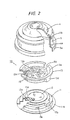
- the lower portion of a cylindrical body fitting 1 and an attachment fitting 2 disposed to an axis center thereof are connected through a vibration isolating substrate 3 made of a rubber elastomer, a diaphragm 4 made of a rubber film is connected above the cylindrical body fitting 1 so as to cover an opening of the upper portion, liquid is contained in an inner chamber between the vibration isolating substrate 3 and the diaphragm 4, a main liquid chamber 6 on the attachment fitting 2 side and a first sub-liquid chamber 7 on the diaphragm side are parted by a partition portion 10, and both liquid chambers 6, 7 are connected by a first orifice 8 formed on an outer circumference of a partition portion 5.
- the cylindrical body fitting 1 assumes a rough cup form of bottom open type having an opening 1a at the bottom, and is connected/fixed and supported by press-fitting means to a holding barrel 52 assuming a rough cup form of bottom open type provided at the upper portion of a support side member 51 as shown in the drawings, with respect to the support side member 51 such as frame on a vehicle body side.
- the cylindrical body fitting 1 can also be supported with other support means connected and secured to an outer circumference of the cylindrical body fitting 1.
- the attachment fitting 2 is in a shape integrally with a flange portion 2a of large diameter, spreading just like an umbrella at the upper extremity of a shaft portion 2b.
- the shaft portion 2b is a boss type capable of screwing a bolt 54 from the lower portion into the axis center.
- the upper end flange portion 2a of the attachment fitting 2 is near the opening at the upper portion of the cylindrical body fitting 1.
- the lower end of the shaft portion is projected downwardly from the opening 1a at the bottom of the cylindrical body fitting 1 and the opening 52a at the bottom of the holding barrel 52.
- a link member 53 on the vibration generating source side such as engine is tightened to the lower extremity of the shaft portion by a bolt 54.
- a rubber portion 55 is attached to the outer circumference of the link member 53. By abutting on the bottom portion of the holding barrel 52, the rubber portion 55 can restrain the link member 53 from displacing upwards largely beyond that.
- Fig. 1 shows the condition that a load such as engine is not applied.
- the rubber portion 55 is held under the condition of being separated from the bottom of the holding barrel 52, and the volume of the first sub-liquid chamber 7 is also reduced.
- the vibration isolating substrate 3 assumes nearly umbrella form.
- the upper portion is vulcanization adhered to the lower surface of the flange portion 2a of the attachment fitting 2 and to the outer circumference of the shaft portion 2b, and the lower extremity is also vulcanization adhered to the inner circumference of the lower extremity of the cylindrical body fitting 1.
- a rubber layer 3a is fitted integrally with the vibration isolating substrate 3 to the inner circumference of the cylindrical body fitting 1.
- the diaphragm 4 has the predetermined curvature and sectional length so as to naturally follow up variation of liquid pressure in the inner chamber, and the outer circumferential portion thereof is vulcanization adhered to the reinforcing cylindrical member 5.
- the cylindrical member 5 is bonded to the cylindrical body fitting 1 when the lower extremity 5a thereof is caulked and secured to the upper extremity 1b of the cylindrical body fitting 1.
- a cylindrical rubber portion 4a of the predetermined thickness molded in one piece to the outer circumferential edge of the diaphragm 4 is vulcanization adhered to the inner circumference of the cylindrical member 5.
- a positioning step portion 4b for abutting and positioning the outer circumferential edge portion of the orifice member 13 is formed at the boundary between the upper end of the cylindrical rubber portion 4a and the outer circumferential edge of the diaphragm 4.
- the partition portion 10 comprises a partition plate member 11 with an elastic film 12 fast stuck to a center opening portion 11a by the vulcanization adhering means, and the orifice member 13 disposed on the first sub-liquid chamber 7 side of the partition plate member 11.
- the partition plate member 11 is formed by vulcanization adhering the elastic film 12 such as rubber and the like to the center opening portion 11a of a press molded metal plate, and an outer circumferential edge portion 11b thereof is fast stuck and fixed to the caulking and tightening portion between the lower extremity 5a of the cylindrical member 5 and the upper extremity 1b of the cylindrical body fitting 1. And, an interconnecting portion 8a connecting from a first orifice 8 to the main liquid chamber 6 is opened on the outer circumferential portion of the partition plate member 11.
- the orifice member 13 is press-fitted and adhered through the cylindrical rubber portion 4a inside the cylindrical member 5, and the outer circumferential edge portion thereof abuts on the positioning step portion 4b at the upper end of the cylindrical rubber portion 4a before positioning.
- An outer circumferential portion 13a assuming a conical form, a center plate portion 13b, and a ring-shaped convex portion 13c present on the lower surface of the circumferential edge portion of the center plate portion 13b are integrally molded by metals such as aluminum and its alloy or ceramics and synthetic resin mold materials to form the orifice member 13.
- the ring-shaped convex portion 13c is pushed and brought into contact with a circumferential portion 12a of the elastic film 12 so as to keep the sealing condition, and a hollow space between the partition plate member 11 and the orifice member 13 is divided into an inward portion and a ring-shaped outward portion.
- the first orifice 8 In the outward portion from the pushing and bringing into contact portion held by the ring-shaped convex portion 13c, the first orifice 8 assuming a nearly ring form, a part of which is shut up by the screen portion 14, is formed between the outer circumferential portion 13a of the orifice member 13 and the stepped outer circumferential portion of the partition plate member 11.
- An interconnecting portion 8b connecting the first orifice 8 with the first sub-liquid chamber 7 is opened on the outer circumferential portion 13a of the orifice member 13.
- the screen portion 14 is formed by a part 13d of the orifice member 13 and a rubber portion 12b vulcanization adhered to the partition plate member 11.
- a hollow space surrounded by the center plate portion 13b of the orifice member 13 and the upper surface of the elastic film 12 is formed as a second sub-liquid chamber 15, and an orifice hole 16 for fraught sound connected from the first sub-liquid chamber 7 to the second sub-liquid chamber 15 is opened on the center plate portion 13b of the orifice member 13.
- the center plate portion 13b of the orifice member 13 assumes in the form of a convex with higher center portion faced toward the first sub-liquid chamber 7.
- the orifice hole 16 is eccentric to the device axis center and present at the low level portion of the center plate portion 13b, and provided at the low level portion where the diaphragm 4 scarecely comes into contact or comes into contact as late as possible, especially when the pressure of the first sub-liquid chamber 7 is reduced due to large downward displacement.
- the upper surface of the center plate portion 13b assumes in the form of a convex surface of the predetermined curvature to the first sub-liquid chamber 7, and the orifice hole 16 is provided at the low level portion within the aforementioned curvature away from the center portion.
- An opening portion of the orifice hole 16 can also be formed by further slightly being lowered below the convex surface of the aforementioned curvature.
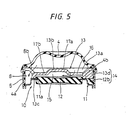
- the center plate portion 13b is not limited to those assuming a convex surface form as shown in Figs.1 to 4, but the center portion 17a, as shown in Fig.5, can be formed to assume a convex form toward the first sub-liquid chamber 7 and the orifice hole 16 can also be formed on the outward side portion 17b which will become the low level portion.
- the step portion between the center portion 17a and the outward portion 17b is formed by continuous R curve to avoid edges from occurring.
- the orifice hole 16 can be formed according to embodiments of other opening form if it is provided at the low level portion of the center plate portion 13b eccentrically disposed from the device axis center. However, in order to prevent the interconnecting portion 8b to the first orifice 8 and the orifice hole 16 from interfering mutually and to secure stable properties, the orifice hole 16 may be provided eccentrically on the reverse side to the position of the interconnecting portion 8b of the outer circumferential portion 13a, desirably by 180.on the opposite side.
- the interconnecting portion 8b to the first orifice 8 may be formed, on the outer circumferential portion 13a of the orifice member 13, at a place where it is difficult for the diaphragm 4 to come into contact even at the time of large downward displacement, especially preferably, so that there is an opening edge on the extended upper surface of the center plate portion 13b, whereby the function of the first orifice 8 can be kept properly.
- the partition plate member 11 is easily produced by vulcanization adhering the elastic film 12 such as rubber to the center opening portion 11a of the press molded metal plate.
- the orifice member 13 made of metals such as aluminum and its alloy or ceramics and synthetic resin mold materials can easily provide dimensional accuracy, thus especially preferable for embodiments. Accordingly, dimensional accuracy of sectional area of the first orifice 8 formed by both members can be improved.
- the liquid-in vibration isolating device made up of the aforementioned configuration is used with the engine and the like supported under a hanging down condition.
- the dynamic spring rate can effectively be reduced in a wider frequency range than ever due to each resonance characteristics of the first orifice 8 and the second orifice 16.
- the first orifice 8 present on the outer circumferential portion of the orifice member 13 is set so as to effectively exhibit vibration damping function in a frequency range of shake vibration.
- the dynamic spring rate can be reduced in each frequency band of the frequency range of shake vibration (10 to 15Hz) and the frequency range of fraught sound (100 to 200Hz), thus effectively bringing about vibration damping in significantly wide frequency range to be able to enhance noise prevention effect.
- the center plate portion 13b of the orifice member 13 is in the form of a convex with the center portion higher faced toward the first sub-liquid chamber 7 side and the orifice hole 16 is disposed at the low level portion of the center plate portion 13b eccentrically with respect to the device axis center. Therefore, even when the diaphragm 4 comes into contact with the center plate portion 13b from the center portion at first, the diaphragm 4 is hardly in contact with the orifice hole 16 as shown in Fig.4 or does not cover the orifice hole 16 earlier or completely if it comes into contact.
- a liquid-in vibration isolating device of the present invention can maintain the function properly, also the function of a first orifice for shake vibration and an orifice hole for fraught sound, without increasing the volume of a first sub-liquid chamber, so as not to cover the orifice hole for fraught sound.
- the dynamic spring rate is effectively reduced in different frequency ranges of shake vibration and fraught sound, whereby vibration and noise preventive effects can be exhibited in a wider frequency range. Furthermore, with regards to the structure of a partition portion, dimensional accuracy of an orifice of an outer circumferential portion for shake vibration can be improved, variation of the properties can also be reduced, thus exhibiting stable vibration isolating properties.
- the present invention can provide optimum liquid-in vibration isolating device for supporting the vibration generating source such as vehicle engine for the purpose of vibration isolation.
Landscapes
- Engineering & Computer Science (AREA)
- General Engineering & Computer Science (AREA)
- Mechanical Engineering (AREA)
- Combined Devices Of Dampers And Springs (AREA)
- Arrangement Or Mounting Of Propulsion Units For Vehicles (AREA)
Applications Claiming Priority (3)
| Application Number | Priority Date | Filing Date | Title |
|---|---|---|---|
| JP2000254149 | 2000-08-24 | ||
| JP2000254149A JP2002070924A (ja) | 2000-08-24 | 2000-08-24 | 液封入式防振装置 |
| PCT/JP2001/006418 WO2002016799A1 (en) | 2000-08-24 | 2001-07-25 | Liquid-in vibration isolating device |
Publications (2)
| Publication Number | Publication Date |
|---|---|
| EP1312829A1 true EP1312829A1 (de) | 2003-05-21 |
| EP1312829A4 EP1312829A4 (de) | 2004-11-17 |
Family
ID=18743148
Family Applications (1)
| Application Number | Title | Priority Date | Filing Date |
|---|---|---|---|
| EP01984524A Withdrawn EP1312829A4 (de) | 2000-08-24 | 2001-07-25 | Hydraulische schwingungsisolationsvorrichtung |
Country Status (4)
| Country | Link |
|---|---|
| US (1) | US6634628B2 (de) |
| EP (1) | EP1312829A4 (de) |
| JP (1) | JP2002070924A (de) |
| WO (1) | WO2002016799A1 (de) |
Families Citing this family (7)
| Publication number | Priority date | Publication date | Assignee | Title |
|---|---|---|---|---|
| JP3858141B2 (ja) * | 2000-06-02 | 2006-12-13 | 東洋ゴム工業株式会社 | 液封入式防振装置 |
| JP3590904B2 (ja) * | 2001-04-16 | 2004-11-17 | 東洋ゴム工業株式会社 | 防振装置 |
| JP3915531B2 (ja) * | 2001-09-28 | 2007-05-16 | 東海ゴム工業株式会社 | 流体封入式防振マウント |
| US7955313B2 (en) * | 2003-12-17 | 2011-06-07 | Boston Scientific Scimed, Inc. | Composite catheter braid |
| US7883071B2 (en) * | 2008-05-21 | 2011-02-08 | Raytheon Company | Methods and apparatus for isolation system |
| CN106224428A (zh) * | 2016-09-07 | 2016-12-14 | 奇瑞汽车股份有限公司 | 一种筒状下拉式液压悬置 |
| US11448286B2 (en) * | 2017-04-27 | 2022-09-20 | Prospira Corporation | Vibration-damping device |
Family Cites Families (14)
| Publication number | Priority date | Publication date | Assignee | Title |
|---|---|---|---|---|
| JPS60184739A (ja) * | 1984-02-21 | 1985-09-20 | Honda Motor Co Ltd | 流体入りマウント |
| US4738435A (en) * | 1985-05-16 | 1988-04-19 | Flower Wallace C | Fluid filled vibration isolator which operates quietly over broad frequency and amplitude ranges |
| US4915365A (en) * | 1987-09-04 | 1990-04-10 | The Standard Products Company | Elastomeric engine mount with hydraulic damping |
| US4762309A (en) * | 1987-09-14 | 1988-08-09 | Saturn Corporation | Hydraulic mount having a flexible decoupler with an orifice therethrough |
| FR2670262B1 (fr) * | 1990-12-10 | 1993-03-19 | Peugeot | Cale hydroelastique. |
| JPH0519696A (ja) | 1991-07-16 | 1993-01-29 | Gifu Shoji:Kk | マガジンデイスプレイ |
| JP2523231Y2 (ja) * | 1991-08-26 | 1997-01-22 | 東海ゴム工業株式会社 | 流体封入式マウントにおける流体室仕切部材 |
| JP3461913B2 (ja) | 1994-06-20 | 2003-10-27 | 株式会社ブリヂストン | 防振装置 |
| JPH109333A (ja) * | 1996-06-27 | 1998-01-13 | Bridgestone Corp | 防振装置 |
| FR2778713B1 (fr) * | 1998-05-13 | 2000-08-04 | Peugeot | Procede de realisation d'une platine intermediaire d'un support hydroelastique et platine intermediaire obtenue par ce procede |
| JP2000230600A (ja) * | 1998-12-11 | 2000-08-22 | Toyo Tire & Rubber Co Ltd | 液封入式防振装置 |
| JP2000274480A (ja) * | 1999-03-24 | 2000-10-03 | Tokai Rubber Ind Ltd | 流体封入式防振装置 |
| US6412760B2 (en) * | 1999-12-27 | 2002-07-02 | Toyoda Gosei Co., Ltd. | Liquid-filled type vibration isolator |
| JP3858141B2 (ja) * | 2000-06-02 | 2006-12-13 | 東洋ゴム工業株式会社 | 液封入式防振装置 |
-
2000
- 2000-08-24 JP JP2000254149A patent/JP2002070924A/ja not_active Withdrawn
-
2001
- 2001-07-25 WO PCT/JP2001/006418 patent/WO2002016799A1/ja not_active Ceased
- 2001-07-25 EP EP01984524A patent/EP1312829A4/de not_active Withdrawn
- 2001-07-25 US US10/049,593 patent/US6634628B2/en not_active Expired - Fee Related
Also Published As
| Publication number | Publication date |
|---|---|
| JP2002070924A (ja) | 2002-03-08 |
| WO2002016799A1 (en) | 2002-02-28 |
| US20020135114A1 (en) | 2002-09-26 |
| US6634628B2 (en) | 2003-10-21 |
| EP1312829A4 (de) | 2004-11-17 |
Similar Documents
| Publication | Publication Date | Title |
|---|---|---|
| US7232118B2 (en) | Fluid filled vibration damping device | |
| EP2047137B1 (de) | Karosserieträger, unterrahmenträger oder motorträger mit sehr hoher dämpfung und schraubendurchgangskonstruktion | |
| US20090079116A1 (en) | Vibration damping device and method of manufacturing the same | |
| US6585242B2 (en) | Switching type liquid-in vibration isolating device | |
| EP0523896B1 (de) | Schwingungsisolierungsgerät | |
| JP2505503Y2 (ja) | 流体封入式マウント装置 | |
| EP1270991B1 (de) | Schwingungsisolierende Vorrichtung | |
| US6523814B2 (en) | Liquid filled vibration isolation device | |
| US6634628B2 (en) | Liquid filled vibration isolation device | |
| US8770559B2 (en) | Liquid sealed vibration isolating device | |
| US7389976B2 (en) | Vibration damping device | |
| US6648312B2 (en) | Liquid-sealed antivibration device | |
| EP1186796A2 (de) | Motorlager | |
| EP1489335B1 (de) | Hydraulisches, schwingungsdämpfendes Lager | |
| JP4842078B2 (ja) | 流体封入式防振装置およびその製造方法 | |
| US11167632B2 (en) | Vibration-damping device | |
| JP4081421B2 (ja) | 防振マウント組立体 | |
| EP3742018B1 (de) | Hydraulisches schwingungsdämpfendes lager | |
| EP1316741A1 (de) | Hydraulische Schwingungsdämpfungseinrichtung | |
| JPH06207637A (ja) | 液体封入式防振マウント | |
| MX2008010811A (es) | Soporte de motor hidraulico con conjunto de llenado lateral. | |
| JP2007263297A (ja) | 流体封入式防振装置 | |
| JP2002235792A (ja) | エンジンマウント用ダストカバー | |
| JPH0732245U (ja) | 液体封入式マウント装置 | |
| JPH0492139A (ja) | 高粘性流体封入式マウント装置 |
Legal Events
| Date | Code | Title | Description |
|---|---|---|---|
| PUAI | Public reference made under article 153(3) epc to a published international application that has entered the european phase |
Free format text: ORIGINAL CODE: 0009012 |
|
| 17P | Request for examination filed |
Effective date: 20030318 |
|
| AK | Designated contracting states |
Designated state(s): DE FR GB |
|
| A4 | Supplementary search report drawn up and despatched |
Effective date: 20040930 |
|
| 17Q | First examination report despatched |
Effective date: 20041201 |
|
| STAA | Information on the status of an ep patent application or granted ep patent |
Free format text: STATUS: THE APPLICATION IS DEEMED TO BE WITHDRAWN |
|
| 18D | Application deemed to be withdrawn |
Effective date: 20051110 |