EP1358005B1 - Luftverteiler und spülverfahren dafür - Google Patents
Luftverteiler und spülverfahren dafür Download PDFInfo
- Publication number
- EP1358005B1 EP1358005B1 EP01999424A EP01999424A EP1358005B1 EP 1358005 B1 EP1358005 B1 EP 1358005B1 EP 01999424 A EP01999424 A EP 01999424A EP 01999424 A EP01999424 A EP 01999424A EP 1358005 B1 EP1358005 B1 EP 1358005B1
- Authority
- EP
- European Patent Office
- Prior art keywords
- air
- flushing
- diffuser tube
- diffuser
- intra
- Prior art date
- Legal status (The legal status is an assumption and is not a legal conclusion. Google has not performed a legal analysis and makes no representation as to the accuracy of the status listed.)
- Expired - Lifetime
Links
- 238000011010 flushing procedure Methods 0.000 title claims abstract description 137
- 238000000034 method Methods 0.000 title claims description 14
- 238000009792 diffusion process Methods 0.000 claims abstract description 36
- 230000010349 pulsation Effects 0.000 claims abstract description 8
- 239000002351 wastewater Substances 0.000 claims description 21
- 239000012528 membrane Substances 0.000 description 86
- 239000010802 sludge Substances 0.000 description 34
- 238000001914 filtration Methods 0.000 description 20
- XLYOFNOQVPJJNP-UHFFFAOYSA-N water Substances O XLYOFNOQVPJJNP-UHFFFAOYSA-N 0.000 description 20
- 238000005273 aeration Methods 0.000 description 18
- QVGXLLKOCUKJST-UHFFFAOYSA-N atomic oxygen Chemical compound [O] QVGXLLKOCUKJST-UHFFFAOYSA-N 0.000 description 14
- 229910052760 oxygen Inorganic materials 0.000 description 14
- 239000001301 oxygen Substances 0.000 description 14
- 238000010276 construction Methods 0.000 description 11
- 230000000694 effects Effects 0.000 description 8
- 238000000926 separation method Methods 0.000 description 8
- 238000011144 upstream manufacturing Methods 0.000 description 7
- 238000004090 dissolution Methods 0.000 description 6
- 230000009471 action Effects 0.000 description 5
- 238000003756 stirring Methods 0.000 description 5
- 238000007664 blowing Methods 0.000 description 4
- 230000008569 process Effects 0.000 description 4
- 230000005484 gravity Effects 0.000 description 3
- 230000009467 reduction Effects 0.000 description 3
- 239000006185 dispersion Substances 0.000 description 2
- 238000006073 displacement reaction Methods 0.000 description 2
- 244000144992 flock Species 0.000 description 2
- 239000012530 fluid Substances 0.000 description 2
- 230000008595 infiltration Effects 0.000 description 2
- 238000001764 infiltration Methods 0.000 description 2
- 239000007788 liquid Substances 0.000 description 2
- 238000012423 maintenance Methods 0.000 description 2
- 230000003252 repetitive effect Effects 0.000 description 2
- 239000007787 solid Substances 0.000 description 2
- 230000003068 static effect Effects 0.000 description 2
- 238000004065 wastewater treatment Methods 0.000 description 2
- 238000012935 Averaging Methods 0.000 description 1
- 206010021143 Hypoxia Diseases 0.000 description 1
- BZHJMEDXRYGGRV-UHFFFAOYSA-N Vinyl chloride Chemical compound ClC=C BZHJMEDXRYGGRV-UHFFFAOYSA-N 0.000 description 1
- 230000002411 adverse Effects 0.000 description 1
- 239000000919 ceramic Substances 0.000 description 1
- 230000008878 coupling Effects 0.000 description 1
- 238000010168 coupling process Methods 0.000 description 1
- 238000005859 coupling reaction Methods 0.000 description 1
- 238000009295 crossflow filtration Methods 0.000 description 1
- 238000010586 diagram Methods 0.000 description 1
- 238000007599 discharging Methods 0.000 description 1
- 239000003657 drainage water Substances 0.000 description 1
- 238000010438 heat treatment Methods 0.000 description 1
- 230000006872 improvement Effects 0.000 description 1
- 238000012986 modification Methods 0.000 description 1
- 230000004048 modification Effects 0.000 description 1
- 230000000737 periodic effect Effects 0.000 description 1
- 230000002093 peripheral effect Effects 0.000 description 1
- 239000011347 resin Substances 0.000 description 1
- 229920005989 resin Polymers 0.000 description 1
- 230000001932 seasonal effect Effects 0.000 description 1
- 239000004065 semiconductor Substances 0.000 description 1
Images


Classifications
-
- B—PERFORMING OPERATIONS; TRANSPORTING
- B01—PHYSICAL OR CHEMICAL PROCESSES OR APPARATUS IN GENERAL
- B01D—SEPARATION
- B01D65/00—Accessories or auxiliary operations, in general, for separation processes or apparatus using semi-permeable membranes
- B01D65/08—Prevention of membrane fouling or of concentration polarisation
-
- C—CHEMISTRY; METALLURGY
- C02—TREATMENT OF WATER, WASTE WATER, SEWAGE, OR SLUDGE
- C02F—TREATMENT OF WATER, WASTE WATER, SEWAGE, OR SLUDGE
- C02F3/00—Biological treatment of water, waste water, or sewage
- C02F3/02—Aerobic processes
- C02F3/12—Activated sludge processes
- C02F3/20—Activated sludge processes using diffusers
-
- B—PERFORMING OPERATIONS; TRANSPORTING
- B01—PHYSICAL OR CHEMICAL PROCESSES OR APPARATUS IN GENERAL
- B01D—SEPARATION
- B01D61/00—Processes of separation using semi-permeable membranes, e.g. dialysis, osmosis or ultrafiltration; Apparatus, accessories or auxiliary operations specially adapted therefor
- B01D61/14—Ultrafiltration; Microfiltration
- B01D61/18—Apparatus therefor
-
- B—PERFORMING OPERATIONS; TRANSPORTING
- B01—PHYSICAL OR CHEMICAL PROCESSES OR APPARATUS IN GENERAL
- B01D—SEPARATION
- B01D63/00—Apparatus in general for separation processes using semi-permeable membranes
- B01D63/08—Flat membrane modules
- B01D63/082—Flat membrane modules comprising a stack of flat membranes
- B01D63/0821—Membrane plate arrangements for submerged operation
-
- B—PERFORMING OPERATIONS; TRANSPORTING
- B01—PHYSICAL OR CHEMICAL PROCESSES OR APPARATUS IN GENERAL
- B01F—MIXING, e.g. DISSOLVING, EMULSIFYING OR DISPERSING
- B01F23/00—Mixing according to the phases to be mixed, e.g. dispersing or emulsifying
- B01F23/20—Mixing gases with liquids
- B01F23/23—Mixing gases with liquids by introducing gases into liquid media, e.g. for producing aerated liquids
- B01F23/231—Mixing gases with liquids by introducing gases into liquid media, e.g. for producing aerated liquids by bubbling
- B01F23/23105—Arrangement or manipulation of the gas bubbling devices
- B01F23/2312—Diffusers
- B01F23/23121—Diffusers having injection means, e.g. nozzles with circumferential outlet
-
- B—PERFORMING OPERATIONS; TRANSPORTING
- B01—PHYSICAL OR CHEMICAL PROCESSES OR APPARATUS IN GENERAL
- B01F—MIXING, e.g. DISSOLVING, EMULSIFYING OR DISPERSING
- B01F23/00—Mixing according to the phases to be mixed, e.g. dispersing or emulsifying
- B01F23/20—Mixing gases with liquids
- B01F23/23—Mixing gases with liquids by introducing gases into liquid media, e.g. for producing aerated liquids
- B01F23/231—Mixing gases with liquids by introducing gases into liquid media, e.g. for producing aerated liquids by bubbling
- B01F23/23105—Arrangement or manipulation of the gas bubbling devices
- B01F23/2312—Diffusers
- B01F23/23123—Diffusers consisting of rigid porous or perforated material
-
- B—PERFORMING OPERATIONS; TRANSPORTING
- B01—PHYSICAL OR CHEMICAL PROCESSES OR APPARATUS IN GENERAL
- B01F—MIXING, e.g. DISSOLVING, EMULSIFYING OR DISPERSING
- B01F23/00—Mixing according to the phases to be mixed, e.g. dispersing or emulsifying
- B01F23/20—Mixing gases with liquids
- B01F23/23—Mixing gases with liquids by introducing gases into liquid media, e.g. for producing aerated liquids
- B01F23/231—Mixing gases with liquids by introducing gases into liquid media, e.g. for producing aerated liquids by bubbling
- B01F23/23105—Arrangement or manipulation of the gas bubbling devices
- B01F23/2312—Diffusers
- B01F23/23126—Diffusers characterised by the shape of the diffuser element
- B01F23/231265—Diffusers characterised by the shape of the diffuser element being tubes, tubular elements, cylindrical elements or set of tubes
-
- B—PERFORMING OPERATIONS; TRANSPORTING
- B01—PHYSICAL OR CHEMICAL PROCESSES OR APPARATUS IN GENERAL
- B01F—MIXING, e.g. DISSOLVING, EMULSIFYING OR DISPERSING
- B01F23/00—Mixing according to the phases to be mixed, e.g. dispersing or emulsifying
- B01F23/20—Mixing gases with liquids
- B01F23/29—Mixing systems, i.e. flow charts or diagrams
-
- B—PERFORMING OPERATIONS; TRANSPORTING
- B01—PHYSICAL OR CHEMICAL PROCESSES OR APPARATUS IN GENERAL
- B01F—MIXING, e.g. DISSOLVING, EMULSIFYING OR DISPERSING
- B01F33/00—Other mixers; Mixing plants; Combinations of mixers
- B01F33/40—Mixers using gas or liquid agitation, e.g. with air supply tubes
- B01F33/405—Mixers using gas or liquid agitation, e.g. with air supply tubes in receptacles having guiding conduits therein, e.g. for feeding the gas to the bottom of the receptacle
- B01F33/4051—Mixers using gas or liquid agitation, e.g. with air supply tubes in receptacles having guiding conduits therein, e.g. for feeding the gas to the bottom of the receptacle with vertical conduits through which the material is being moved upwardly driven by the fluid
- B01F33/40512—Mixers using gas or liquid agitation, e.g. with air supply tubes in receptacles having guiding conduits therein, e.g. for feeding the gas to the bottom of the receptacle with vertical conduits through which the material is being moved upwardly driven by the fluid involving gas diffusers at the bottom
-
- C—CHEMISTRY; METALLURGY
- C02—TREATMENT OF WATER, WASTE WATER, SEWAGE, OR SLUDGE
- C02F—TREATMENT OF WATER, WASTE WATER, SEWAGE, OR SLUDGE
- C02F1/00—Treatment of water, waste water, or sewage
- C02F1/44—Treatment of water, waste water, or sewage by dialysis, osmosis or reverse osmosis
- C02F1/444—Treatment of water, waste water, or sewage by dialysis, osmosis or reverse osmosis by ultrafiltration or microfiltration
-
- C—CHEMISTRY; METALLURGY
- C02—TREATMENT OF WATER, WASTE WATER, SEWAGE, OR SLUDGE
- C02F—TREATMENT OF WATER, WASTE WATER, SEWAGE, OR SLUDGE
- C02F3/00—Biological treatment of water, waste water, or sewage
- C02F3/02—Aerobic processes
- C02F3/12—Activated sludge processes
- C02F3/1236—Particular type of activated sludge installations
- C02F3/1268—Membrane bioreactor systems
- C02F3/1273—Submerged membrane bioreactors
-
- C—CHEMISTRY; METALLURGY
- C02—TREATMENT OF WATER, WASTE WATER, SEWAGE, OR SLUDGE
- C02F—TREATMENT OF WATER, WASTE WATER, SEWAGE, OR SLUDGE
- C02F3/00—Biological treatment of water, waste water, or sewage
- C02F3/30—Aerobic and anaerobic processes
- C02F3/302—Nitrification and denitrification treatment
-
- B—PERFORMING OPERATIONS; TRANSPORTING
- B01—PHYSICAL OR CHEMICAL PROCESSES OR APPARATUS IN GENERAL
- B01D—SEPARATION
- B01D2321/00—Details relating to membrane cleaning, regeneration, sterilization or to the prevention of fouling
- B01D2321/18—Use of gases
- B01D2321/185—Aeration
-
- B—PERFORMING OPERATIONS; TRANSPORTING
- B01—PHYSICAL OR CHEMICAL PROCESSES OR APPARATUS IN GENERAL
- B01D—SEPARATION
- B01D2321/00—Details relating to membrane cleaning, regeneration, sterilization or to the prevention of fouling
- B01D2321/20—By influencing the flow
- B01D2321/2066—Pulsated flow
-
- B—PERFORMING OPERATIONS; TRANSPORTING
- B01—PHYSICAL OR CHEMICAL PROCESSES OR APPARATUS IN GENERAL
- B01F—MIXING, e.g. DISSOLVING, EMULSIFYING OR DISPERSING
- B01F23/00—Mixing according to the phases to be mixed, e.g. dispersing or emulsifying
- B01F23/20—Mixing gases with liquids
- B01F23/23—Mixing gases with liquids by introducing gases into liquid media, e.g. for producing aerated liquids
- B01F23/231—Mixing gases with liquids by introducing gases into liquid media, e.g. for producing aerated liquids by bubbling
- B01F23/23105—Arrangement or manipulation of the gas bubbling devices
- B01F23/2311—Mounting the bubbling devices or the diffusers
- B01F23/23113—Mounting the bubbling devices or the diffusers characterised by the disposition of the bubbling elements in particular configurations, patterns or arrays
-
- B—PERFORMING OPERATIONS; TRANSPORTING
- B01—PHYSICAL OR CHEMICAL PROCESSES OR APPARATUS IN GENERAL
- B01F—MIXING, e.g. DISSOLVING, EMULSIFYING OR DISPERSING
- B01F23/00—Mixing according to the phases to be mixed, e.g. dispersing or emulsifying
- B01F23/20—Mixing gases with liquids
- B01F23/23—Mixing gases with liquids by introducing gases into liquid media, e.g. for producing aerated liquids
- B01F23/231—Mixing gases with liquids by introducing gases into liquid media, e.g. for producing aerated liquids by bubbling
- B01F23/23105—Arrangement or manipulation of the gas bubbling devices
- B01F23/2312—Diffusers
- B01F23/23123—Diffusers consisting of rigid porous or perforated material
- B01F23/231231—Diffusers consisting of rigid porous or perforated material the outlets being in the form of perforations
-
- B—PERFORMING OPERATIONS; TRANSPORTING
- B01—PHYSICAL OR CHEMICAL PROCESSES OR APPARATUS IN GENERAL
- B01F—MIXING, e.g. DISSOLVING, EMULSIFYING OR DISPERSING
- B01F35/00—Accessories for mixers; Auxiliary operations or auxiliary devices; Parts or details of general application
- B01F35/20—Measuring; Control or regulation
-
- C—CHEMISTRY; METALLURGY
- C02—TREATMENT OF WATER, WASTE WATER, SEWAGE, OR SLUDGE
- C02F—TREATMENT OF WATER, WASTE WATER, SEWAGE, OR SLUDGE
- C02F3/00—Biological treatment of water, waste water, or sewage
- C02F3/02—Aerobic processes
- C02F3/12—Activated sludge processes
-
- Y—GENERAL TAGGING OF NEW TECHNOLOGICAL DEVELOPMENTS; GENERAL TAGGING OF CROSS-SECTIONAL TECHNOLOGIES SPANNING OVER SEVERAL SECTIONS OF THE IPC; TECHNICAL SUBJECTS COVERED BY FORMER USPC CROSS-REFERENCE ART COLLECTIONS [XRACs] AND DIGESTS
- Y02—TECHNOLOGIES OR APPLICATIONS FOR MITIGATION OR ADAPTATION AGAINST CLIMATE CHANGE
- Y02W—CLIMATE CHANGE MITIGATION TECHNOLOGIES RELATED TO WASTEWATER TREATMENT OR WASTE MANAGEMENT
- Y02W10/00—Technologies for wastewater treatment
- Y02W10/10—Biological treatment of water, waste water, or sewage
-
- Y—GENERAL TAGGING OF NEW TECHNOLOGICAL DEVELOPMENTS; GENERAL TAGGING OF CROSS-SECTIONAL TECHNOLOGIES SPANNING OVER SEVERAL SECTIONS OF THE IPC; TECHNICAL SUBJECTS COVERED BY FORMER USPC CROSS-REFERENCE ART COLLECTIONS [XRACs] AND DIGESTS
- Y10—TECHNICAL SUBJECTS COVERED BY FORMER USPC
- Y10S—TECHNICAL SUBJECTS COVERED BY FORMER USPC CROSS-REFERENCE ART COLLECTIONS [XRACs] AND DIGESTS
- Y10S261/00—Gas and liquid contact apparatus
- Y10S261/70—Sewage aerators; diffusers
Definitions
- Membrane separators used in membrane separation activated sludge process for biologically treating waste water, drainage water etc have a plurality of membrane cartridges.
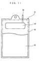
- a membrane cartridge 51 has filtration membranes 53 disposed on the front and rear surfaces of a filter supporting plate 52 made of resin, and the entire peripheral portions of the filtration membranes 53 are fused to the filter supporting plate 52 by heating with a heater or by ultrasonic vibration.
- a transmitted liquor passage is present between the filter supporting plate 52 and each filtration membrane 53.
- a collecting hole 54 communicated to the transmitted liquor passage extends from front to rear of the filter supporting plate 52.
- a transmitted liquor outlet 55 communicated to the collecting hole 54 is disposed at an upper end of the filter supporting plate 52.
- the membrane separator has an air diffuser disposed under the membrane cartridges 51.
- the air diffuser is obtained only by boring a plurality of holes of approximately ⁇ 10 mm in a lower part of a pipe made of vinyl chloride.
- the opening at the tip of the branch pipes serves as the blowhole, the inside diameter of the branch pipes and the aperture of the blowhole are the same. This provides a shape having no variations in the sectional area of the passage. Also, there is no resistance to obstruct the fluid passing from the branch pipes via the blowholes to the exterior. Therefore, the sludge and intra-tank mixed liquor that remain in the branch pipes when changing from the flushing state to the air diffusion state, are quickly discharged to the outside of the branch pipes at the time of air diffusion. Otherwise, the resulting effects are the same as the first aspect.
- the intra-tank mixed liquor flows from the opening at the tip of the branch pipes and from the blowholes to the branch pipes.
- This intra-tank mixed liquor is joined with air to pass through the branch pipes to the main pipe while flushing the inside of the diffuser tube, and then joined with cumulus deposit within the diffuser tube to come off together from the outlet via the flushing pipe. Otherwise, the resulting effects are the same as the first aspect.
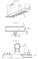
- a diffuser casing 4 of the air diffuser 2 is disposed below the membrane separator 3 so as to surround its lower region, and a diffuser tube 5 is located at a lower position of the diffuser case 4.
- the diffuser tube 5 is made up of a main pipe 6 composed of a large-diameter pipe having a predetermined aperture and extending horizontally, and a plurality of branch pipes 7 formed by small-diameter pipes, each having a predetermined aperture and locating underneath the main pipe 6.
- sludge is attched which enters the diffuser tube 5 when the operation of the blower 8 of the air diffuser 2 is stopped, and which is then dried by the air passing through the diffuser tube 5 during air diffusion.
- Infiltration of the intra-tank mixed liquor facilitates the release of the dry sludge from the inner surface of the pipe.
- the released sludge is joined with the intra-tank mixed liquor to come off together from the outlet 11 as the air is discharged.
- the openings at the tip of the branch pipes 7 serve as the blowhole 10, the inner diameter of the branch pipes and the aperture of the blowhole 10 are the same. This provides a shape having no variations in the sectional area of the passage. Also, there is no resistance to obstruct the fluid passing through the inside of the branch pipes 7 and blowholes 10 to the exterior. Therefore, the sludge and intra-tank mixed liquor that remain in the branch pipes 7 when changing from the flushing state to the air diffusion state, are quickly discharged to the outside of the branch pipes 7 during air diffusion.
- the controller 16 opens/closes the flushing valve 12 to automatically perform switching between .the air diffusion operation and the flushing operation. Therefore, the flushing operation can be performed automatically at a particular time that waste water flow is below a predetermined value, or at predetermined time-spaced intervals.
- the flushing operation at that particular time prevents excessive air diffusion that adversely affects the filtration membranes of the membrane separator 3, and also performs flushing of the diffuser tube 5. Further, even if a slight flow of waste water continues for a long period of time, the intra-tank mixed liquor is stirred in the air diffusion state to be produced intermittently, and oxygen can be supplied to activated sludge. In addition, in the flushing state, the intra-tank mixed liquor joins with air to flow together through the diffuser tube 5 and flushing pipe 9, so that sufficient oxygen is dissolved in the intra-tank mixed liquor. Therefore, by returning the intra-tank mixed liquor discharged from the flushing pipe 9 to the aeration tank 1, the oxygen supply to the intra-tank mixed liquor and the stirring of the intra-tank mixed liquor are performable even in the flushing state.
- the diffuser tube 5 is subjected to repetitive flushing by using pulsation generated in the inside of the diffuser tube 5 and flushing pipe 9. This avoids that the main pipe 6, branch pipes 7 and blowholes 10 become clogged by dry sludge.
- a flushing water tank nor a flushing pump is necessary, which have conventionally been required. This leads to a reduction in the load on the maintenance operator.
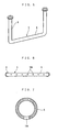
- the air passing through the branch pipes 7 receives buoyancy due to a density difference with the intra-tank mixed liquor. Therefore, most of the air blows off from the blowholes lOb, and the rest is discharged from the opening 10a at the tip. Since the blowholes 10b have a small aperture, the small bubble (fine bubble) of the air blowing off therefrom has a small diameter, which increases the efficiency of oxygen dissolution. The improved efficiency of oxygen dissolution reduces the size of the blower 8 as an air source, thus permitting a reduction in power consumption.
- the total amount of air diffused from the diffuser tube 5 be controlled to a predetermined amount. Therefore, as the aperture of the blowholes 10b is increased, the number of the blowholes 10b must be reduced. However, in the second preferred embodiment, the number of the blowholes 10b can be increased by reducing their aperture. Thereby, the degree of dispersion of the blowholes 10b in the aeration tank 1 can be increased to uniformly diffuse the aerated air and increase the effect of flushing the membrane surfaces of the membrane separator 3.
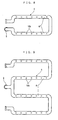
- a third preferred embodiment has the same basic construction as that shown in Figs. 1 to 3 in the first preferred embodiment.
- a diffuser tube 5 that is an important part of the third preferred embodiment will be described.
- the same references have been used as in Figs. 1 to 3, and their detailed description is omitted.
Landscapes
- Chemical & Material Sciences (AREA)
- Chemical Kinetics & Catalysis (AREA)
- Life Sciences & Earth Sciences (AREA)
- Water Supply & Treatment (AREA)
- Engineering & Computer Science (AREA)
- Organic Chemistry (AREA)
- Hydrology & Water Resources (AREA)
- Environmental & Geological Engineering (AREA)
- Microbiology (AREA)
- Biodiversity & Conservation Biology (AREA)
- Aeration Devices For Treatment Of Activated Polluted Sludge (AREA)
- Activated Sludge Processes (AREA)
- Separation Using Semi-Permeable Membranes (AREA)
- Mixers With Rotating Receptacles And Mixers With Vibration Mechanisms (AREA)
- Jet Pumps And Other Pumps (AREA)
- Cleaning By Liquid Or Steam (AREA)
- Vaporization, Distillation, Condensation, Sublimation, And Cold Traps (AREA)
- Separation By Low-Temperature Treatments (AREA)
Claims (7)
- Eine Luftverteilervorrichtung (2) für die Venrvendung in einem Behälter (1), umfassend:Eine Luftzuführung (8), ein Verteilerrohr (5), das seitwärts in den Behälter (1) eintaucht, wobei genanntes Verteilerrohr (5) an seinem unteren Abschnitt mehrere Blaslöcher (10) aufweist und es an seinem Basisende mit der genannten Luftzuführung (8) verbunden ist; dadurch gekennzeichnet, dass sie ein Spülrohr (9) umfasst, welches an seinem Basisende mit der Spitze des Verteilerrohrs (5) verbunden ist und sich an der Spitze als ein Auslass (11) an einer oberen Position des Verteilerrohrs (5) öffnet; und sie ein in dem Spülrohr (9) angeordnetes Spülventil (12) aufweist.
- Die Luftverteilervorrichtung (2) nach Anspruch 1, dadurch gekennzeichnet, dass das Verteilerrohr (5) umfasst:Ein Hauptrohr (6), das an seinem Basisende mit einer Luftzuführung (8) und an seiner Spitze mit dem Spülrohr (9) verbunden ist; und mehrere Abzweigrohre (7), die mit dem Hauptrohr (6) verbunden sind und sich an ihrer Spitze jeweils als ein Blasloch (10) in einer Position unter dem Hauptrohr (6) öffnen.
- Die Luftverteilervorrichtung (2) nach Anspruch 1 oder 2, dadurch gekennzeichnet, dass die Abzweigrohre (7) mehrere Blaslöcher (10b) aufweisen, wobei deren Durchlass kleiner ist als die Öffnung (10a) an deren Spitze.
- Die Luftverteilervorrichtung (2) nach einem der Ansprüche 1 bis 3, dadurch gekennzeichnet, dass sie eine Sensorvorrichtung (15) zur Messung der Menge des Abwasserdurchflusses in den Behälter (1) aufweist; und
eine Steuervorrichtung (16), um das Spülventil (12) bei einer bestimmten Zeit zu öffnen, wenn die Sensorvorrichtung (15) erkennt, dass die Menge des Abwasserdurchflusses unter einem vorherbestimmten Wert liegt. - Die Luftverteilervorrichtung (2) nach einem der Ansprüche 1 bis 3, dadurch gekennzeichnet, dass sie eine Steuervorrichtung (16) aufweist, um das Spülventil (12) zu vorherbestimmten, zeitlich beabstandeten Intervallen, die durch einen Zeitschalter eingestellt sind, zu öffnen.
- Ein Verfahren zum Spülen eines Verteilerrohres (5) in einer Luftverteilervorrichtung (2) nach einem der Ansprüche 1 bis 3, dadurch gekennzeichnet, dass während der Luftverteilung Luft durch die Luftzuführung (8) bei geschlossenem Spülventil (12) zugeführt wird und die Luft aus den Blaslöchern (10) verteilt wird, und, dass während der Spülung Luft durch die Luftzuführung (8) bei geöffnetem Spülventil (12) zugeführt wird und eine Mischflüssigkeit innerhalb des Behälters von den Öffnungen (10) des Verteilerrohres (5) angesaugt wird, so dass das Innere des Verteilerrohres (5) mit der angesaugten, aus dem Behälter stammenden Mischflüssigkeit gespült wird und die aus dem Behälter stammende Mischflüssigkeit dann mit der Luft zusammengeführt wird und zusammen mit der Luft aus dem Auslass (11) des Spülrohres (9) austritt.
- Das Verfahren zum Spülen einer Luftverteilervorrichtung (2) nach Anspruch 6, dadurch gekennzeichnet, dass die Verteilung der Luft aus den Blaslöchern (10) und die Spülung des Verteilerrohres (5) sich abwechselnd wiederholen, indem eine durch Druckänderungen verursachte Pulsation im Verteilerrohr (5) während des Spülens angewendet wird.
Applications Claiming Priority (7)
| Application Number | Priority Date | Filing Date | Title |
|---|---|---|---|
| JP2000367855 | 2000-12-04 | ||
| JP2000367855A JP3382926B2 (ja) | 2000-12-04 | 2000-12-04 | 散気装置の洗浄方法および散気装置 |
| JP2000389658 | 2000-12-22 | ||
| JP2000389657 | 2000-12-22 | ||
| JP2000389658A JP3784252B2 (ja) | 2000-12-22 | 2000-12-22 | 散気装置 |
| JP2000389657A JP3859447B2 (ja) | 2000-12-22 | 2000-12-22 | 散気方法および装置 |
| PCT/JP2001/010297 WO2002045833A1 (en) | 2000-12-04 | 2001-11-26 | Air diffuser and flushing method thereof |
Publications (2)
| Publication Number | Publication Date |
|---|---|
| EP1358005A1 EP1358005A1 (de) | 2003-11-05 |
| EP1358005B1 true EP1358005B1 (de) | 2006-12-27 |
Family
ID=27345352
Family Applications (1)
| Application Number | Title | Priority Date | Filing Date |
|---|---|---|---|
| EP01999424A Expired - Lifetime EP1358005B1 (de) | 2000-12-04 | 2001-11-26 | Luftverteiler und spülverfahren dafür |
Country Status (10)
| Country | Link |
|---|---|
| US (1) | US6843470B2 (de) |
| EP (1) | EP1358005B1 (de) |
| KR (1) | KR100768873B1 (de) |
| CN (1) | CN1204961C (de) |
| AT (1) | ATE349271T1 (de) |
| AU (1) | AU783464B2 (de) |
| CA (1) | CA2398460C (de) |
| DE (1) | DE60125594T2 (de) |
| ES (1) | ES2282329T3 (de) |
| WO (1) | WO2002045833A1 (de) |
Families Citing this family (25)
| Publication number | Priority date | Publication date | Assignee | Title |
|---|---|---|---|---|
| US6706189B2 (en) | 1998-10-09 | 2004-03-16 | Zenon Environmental Inc. | Cyclic aeration system for submerged membrane modules |
| US6863817B2 (en) * | 2002-12-05 | 2005-03-08 | Zenon Environmental Inc. | Membrane bioreactor, process and aerator |
| US7452457B2 (en) * | 2003-06-20 | 2008-11-18 | Roche Diagnostics Operations, Inc. | System and method for analyte measurement using dose sufficiency electrodes |
| US7488601B2 (en) * | 2003-06-20 | 2009-02-10 | Roche Diagnostic Operations, Inc. | System and method for determining an abused sensor during analyte measurement |
| US8148164B2 (en) | 2003-06-20 | 2012-04-03 | Roche Diagnostics Operations, Inc. | System and method for determining the concentration of an analyte in a sample fluid |
| MY140160A (en) * | 2004-01-28 | 2009-11-30 | Shell Int Research | Heat exchanger for carrying out an exothermic reaction |
| DE602005022833D1 (de) * | 2004-03-08 | 2010-09-23 | Shell Int Research | Filtersystem mit in ein gehäuse zurückziehbaren filtermitteln |
| JP2007527793A (ja) * | 2004-03-08 | 2007-10-04 | シエル・インターナシヨネイル・リサーチ・マーチヤツピイ・ベー・ウイ | 反応器用のガス分配器 |
| CN1323029C (zh) * | 2004-12-10 | 2007-06-27 | 中国科学院长春应用化学研究所 | 燃烧聚烯烃合成碳纳米管的方法 |
| EP2168665A4 (de) * | 2007-07-04 | 2011-05-04 | Mitsubishi Rayon Co | Verfahren zur reinigung einer luftdiffusorvorrichtung |
| US8206495B2 (en) * | 2009-06-23 | 2012-06-26 | Sam Yung Kwack | Gas filtration system |
| KR20130035415A (ko) * | 2011-09-30 | 2013-04-09 | 코오롱인더스트리 주식회사 | 산기부 및 그것을 포함한 여과장치 |
| JP5801182B2 (ja) * | 2011-12-27 | 2015-10-28 | 三機工業株式会社 | 散気システムの運転方法 |
| US8276890B1 (en) * | 2012-01-31 | 2012-10-02 | Gerald Kloehn | Pressure monitoring panel for aeration basins |
| CN104870377B (zh) * | 2012-10-19 | 2018-03-13 | 三菱化学株式会社 | 散气装置、散气方法及水处理装置 |
| WO2014065268A1 (ja) * | 2012-10-25 | 2014-05-01 | 三菱レイヨン株式会社 | 散気装置とその運転方法、及び水処理装置 |
| KR101608457B1 (ko) | 2014-09-29 | 2016-04-01 | 주식회사 티이애플리케이션 | 항온용 저장탱크 |
| CN105036376B (zh) * | 2015-08-31 | 2017-05-31 | 广东鑫都环保实业有限公司 | 一种曝气系统的防堵方法及一种无堵塞曝气系统 |
| CN105437772B (zh) * | 2015-12-17 | 2017-06-20 | 重庆宏劲印务有限责任公司 | 一种喷墨打印机喷头清洗装置 |
| KR101818825B1 (ko) * | 2015-12-24 | 2018-01-16 | 씨제이제일제당 (주) | 연속식 발효장치 |
| FR3061663B1 (fr) * | 2017-01-06 | 2019-05-17 | Suez Groupe | Systeme ameliore d'aeration de membrane immergee |
| US12324895B2 (en) * | 2019-11-08 | 2025-06-10 | Global Life Sciences Solutions Usa Llc | Sparger device for a bioprocessing system and method of manufacturing a sparger device |
| CN111995081B (zh) * | 2020-08-24 | 2022-07-12 | 吴建芳 | 一种无堵塞微孔曝气系统 |
| CN114405927B (zh) * | 2022-03-28 | 2022-07-15 | 龙口市动力油管有限公司 | 一种异形多喷孔喷油管复合式清洁度处理装置 |
| CN119082391B (zh) * | 2024-08-29 | 2025-09-16 | 宝钢湛江钢铁有限公司 | 一种氢基竖炉气体分离器排水防堵塞方法 |
Family Cites Families (9)
| Publication number | Priority date | Publication date | Assignee | Title |
|---|---|---|---|---|
| DE813995C (de) | 1948-10-02 | 1951-09-17 | Bertram Mueller G M B H | Einrichtung zum Feinbelueften bzw. Durchgasen von Fluessigkeiten |
| JPS5613087A (en) | 1979-07-11 | 1981-02-07 | Mitsui Miike Mach Co Ltd | Preventing device for clogging of floating type activated sludge air diffusion device |
| US6200468B1 (en) * | 1980-09-29 | 2001-03-13 | Sanitaire Corporation | Aeration system apparatus with source of in situ cleaning agent and pressure monitoring connection for submerged diffuser |
| JPS58141796A (ja) | 1982-02-18 | 1983-08-23 | Kyowa Hakko Kogyo Co Ltd | ペプチドの製造法 |
| US4474714A (en) | 1983-07-15 | 1984-10-02 | Endurex Corp. | Diffuser apparatus |
| US5051193A (en) * | 1986-03-06 | 1991-09-24 | Aeration Engineering Resources Corporation | Waste water treatment process |
| JPS62258729A (ja) | 1986-05-02 | 1987-11-11 | Mitsubishi Heavy Ind Ltd | 通気タンク用気体吹込方法 |
| JPH0620520B2 (ja) * | 1986-09-18 | 1994-03-23 | 三菱重工業株式会社 | 散気ノズルの洗浄方法 |
| JPS63137741A (ja) | 1986-11-28 | 1988-06-09 | Mitsubishi Heavy Ind Ltd | 通気タンク用気体吹込装置 |
-
2001
- 2001-11-26 EP EP01999424A patent/EP1358005B1/de not_active Expired - Lifetime
- 2001-11-26 WO PCT/JP2001/010297 patent/WO2002045833A1/en not_active Ceased
- 2001-11-26 CA CA 2398460 patent/CA2398460C/en not_active Expired - Lifetime
- 2001-11-26 US US10/182,564 patent/US6843470B2/en not_active Expired - Lifetime
- 2001-11-26 CN CNB018045073A patent/CN1204961C/zh not_active Expired - Lifetime
- 2001-11-26 AT AT01999424T patent/ATE349271T1/de not_active IP Right Cessation
- 2001-11-26 ES ES01999424T patent/ES2282329T3/es not_active Expired - Lifetime
- 2001-11-26 DE DE2001625594 patent/DE60125594T2/de not_active Expired - Lifetime
- 2001-11-26 AU AU24103/02A patent/AU783464B2/en not_active Expired
- 2001-11-26 KR KR1020027010060A patent/KR100768873B1/ko not_active Expired - Fee Related
Also Published As
| Publication number | Publication date |
|---|---|
| CN1204961C (zh) | 2005-06-08 |
| AU783464B2 (en) | 2005-10-27 |
| AU2410302A (en) | 2002-06-18 |
| US6843470B2 (en) | 2005-01-18 |
| CN1398198A (zh) | 2003-02-19 |
| DE60125594D1 (de) | 2007-02-08 |
| DE60125594T2 (de) | 2007-10-11 |
| CA2398460C (en) | 2007-10-30 |
| ES2282329T3 (es) | 2007-10-16 |
| WO2002045833A1 (en) | 2002-06-13 |
| CA2398460A1 (en) | 2002-06-26 |
| KR20030013370A (ko) | 2003-02-14 |
| ATE349271T1 (de) | 2007-01-15 |
| EP1358005A1 (de) | 2003-11-05 |
| KR100768873B1 (ko) | 2007-10-19 |
| US20030001295A1 (en) | 2003-01-02 |
Similar Documents
| Publication | Publication Date | Title |
|---|---|---|
| EP1358005B1 (de) | Luftverteiler und spülverfahren dafür | |
| US6843908B2 (en) | Multistage immersion type membrane separator and high-concentration wastewater treatment facility using same | |
| US5192456A (en) | Apparatus for treating activated sludge and method of cleaning it | |
| JP3744425B2 (ja) | 膜分離廃水処理装置 | |
| JP4530621B2 (ja) | 散気装置の洗浄方法 | |
| JPH09253685A (ja) | 散気装置 | |
| JPH11138190A (ja) | 散気装置の運転方法およびそれを実施する散気装置 | |
| JP3382926B2 (ja) | 散気装置の洗浄方法および散気装置 | |
| JP3859447B2 (ja) | 散気方法および装置 | |
| JP3784252B2 (ja) | 散気装置 | |
| JP4618899B2 (ja) | 汚泥移送装置 | |
| KR100788202B1 (ko) | 인공 폭기 장치 | |
| JPH11169868A (ja) | 炭酸ガス中和装置 | |
| CN222498759U (zh) | 推流装置及污水处理系统 | |
| JP3884641B2 (ja) | オキシデーションディッチ | |
| KR200309172Y1 (ko) | 축산분뇨 발효조의 외기공급용 에어노즐 | |
| JP2002233738A (ja) | 浸漬平膜分離装置 | |
| JPH0584495A (ja) | 廃水処理装置およびその洗浄方法 | |
| JP2001179240A (ja) | 微細気泡発生装置 | |
| JPH10225686A (ja) | 汚水処理装置 | |
| JPH09150168A (ja) | 汚水処理装置 | |
| JPH09313820A (ja) | 浄化装置 | |
| JPH09150171A (ja) | 汚水処理装置 | |
| JPH07185582A (ja) | 水処理装置 |
Legal Events
| Date | Code | Title | Description |
|---|---|---|---|
| PUAI | Public reference made under article 153(3) epc to a published international application that has entered the european phase |
Free format text: ORIGINAL CODE: 0009012 |
|
| 17P | Request for examination filed |
Effective date: 20030704 |
|
| AK | Designated contracting states |
Kind code of ref document: A1 Designated state(s): AT BE CH CY DE DK ES FI FR GB GR IE IT LI LU MC NL PT SE TR |
|
| AX | Request for extension of the european patent |
Extension state: AL LT LV MK RO SI |
|
| RIC1 | Information provided on ipc code assigned before grant |
Ipc: B01F 15/00 20060101ALI20060426BHEP Ipc: B08B 9/032 20060101ALI20060426BHEP Ipc: B01F 3/04 20060101AFI20060426BHEP Ipc: C02F 3/00 20060101ALN20060426BHEP |
|
| GRAP | Despatch of communication of intention to grant a patent |
Free format text: ORIGINAL CODE: EPIDOSNIGR1 |
|
| GRAS | Grant fee paid |
Free format text: ORIGINAL CODE: EPIDOSNIGR3 |
|
| GRAA | (expected) grant |
Free format text: ORIGINAL CODE: 0009210 |
|
| AK | Designated contracting states |
Kind code of ref document: B1 Designated state(s): AT BE CH CY DE DK ES FI FR GB GR IE IT LI LU MC NL PT SE TR |
|
| PG25 | Lapsed in a contracting state [announced via postgrant information from national office to epo] |
Ref country code: FI Free format text: LAPSE BECAUSE OF FAILURE TO SUBMIT A TRANSLATION OF THE DESCRIPTION OR TO PAY THE FEE WITHIN THE PRESCRIBED TIME-LIMIT Effective date: 20061227 Ref country code: DK Free format text: LAPSE BECAUSE OF FAILURE TO SUBMIT A TRANSLATION OF THE DESCRIPTION OR TO PAY THE FEE WITHIN THE PRESCRIBED TIME-LIMIT Effective date: 20061227 Ref country code: LI Free format text: LAPSE BECAUSE OF FAILURE TO SUBMIT A TRANSLATION OF THE DESCRIPTION OR TO PAY THE FEE WITHIN THE PRESCRIBED TIME-LIMIT Effective date: 20061227 Ref country code: AT Free format text: LAPSE BECAUSE OF FAILURE TO SUBMIT A TRANSLATION OF THE DESCRIPTION OR TO PAY THE FEE WITHIN THE PRESCRIBED TIME-LIMIT Effective date: 20061227 Ref country code: CH Free format text: LAPSE BECAUSE OF FAILURE TO SUBMIT A TRANSLATION OF THE DESCRIPTION OR TO PAY THE FEE WITHIN THE PRESCRIBED TIME-LIMIT Effective date: 20061227 |
|
| REG | Reference to a national code |
Ref country code: GB Ref legal event code: FG4D |
|
| REG | Reference to a national code |
Ref country code: IE Ref legal event code: FG4D |
|
| REF | Corresponds to: |
Ref document number: 60125594 Country of ref document: DE Date of ref document: 20070208 Kind code of ref document: P |
|
| PG25 | Lapsed in a contracting state [announced via postgrant information from national office to epo] |
Ref country code: SE Free format text: LAPSE BECAUSE OF FAILURE TO SUBMIT A TRANSLATION OF THE DESCRIPTION OR TO PAY THE FEE WITHIN THE PRESCRIBED TIME-LIMIT Effective date: 20070327 |
|
| PG25 | Lapsed in a contracting state [announced via postgrant information from national office to epo] |
Ref country code: PT Free format text: LAPSE BECAUSE OF FAILURE TO SUBMIT A TRANSLATION OF THE DESCRIPTION OR TO PAY THE FEE WITHIN THE PRESCRIBED TIME-LIMIT Effective date: 20070528 |
|
| REG | Reference to a national code |
Ref country code: CH Ref legal event code: PL |
|
| ET | Fr: translation filed | ||
| REG | Reference to a national code |
Ref country code: ES Ref legal event code: FG2A Ref document number: 2282329 Country of ref document: ES Kind code of ref document: T3 |
|
| PLBE | No opposition filed within time limit |
Free format text: ORIGINAL CODE: 0009261 |
|
| STAA | Information on the status of an ep patent application or granted ep patent |
Free format text: STATUS: NO OPPOSITION FILED WITHIN TIME LIMIT |
|
| 26N | No opposition filed |
Effective date: 20070928 |
|
| PG25 | Lapsed in a contracting state [announced via postgrant information from national office to epo] |
Ref country code: GR Free format text: LAPSE BECAUSE OF FAILURE TO SUBMIT A TRANSLATION OF THE DESCRIPTION OR TO PAY THE FEE WITHIN THE PRESCRIBED TIME-LIMIT Effective date: 20070328 |
|
| PG25 | Lapsed in a contracting state [announced via postgrant information from national office to epo] |
Ref country code: MC Free format text: LAPSE BECAUSE OF NON-PAYMENT OF DUE FEES Effective date: 20071130 |
|
| PG25 | Lapsed in a contracting state [announced via postgrant information from national office to epo] |
Ref country code: IE Free format text: LAPSE BECAUSE OF NON-PAYMENT OF DUE FEES Effective date: 20071126 |
|
| PG25 | Lapsed in a contracting state [announced via postgrant information from national office to epo] |
Ref country code: CY Free format text: LAPSE BECAUSE OF FAILURE TO SUBMIT A TRANSLATION OF THE DESCRIPTION OR TO PAY THE FEE WITHIN THE PRESCRIBED TIME-LIMIT Effective date: 20061227 Ref country code: LU Free format text: LAPSE BECAUSE OF NON-PAYMENT OF DUE FEES Effective date: 20071126 |
|
| PG25 | Lapsed in a contracting state [announced via postgrant information from national office to epo] |
Ref country code: TR Free format text: LAPSE BECAUSE OF FAILURE TO SUBMIT A TRANSLATION OF THE DESCRIPTION OR TO PAY THE FEE WITHIN THE PRESCRIBED TIME-LIMIT Effective date: 20061227 |
|
| REG | Reference to a national code |
Ref country code: FR Ref legal event code: PLFP Year of fee payment: 15 |
|
| REG | Reference to a national code |
Ref country code: FR Ref legal event code: PLFP Year of fee payment: 16 |
|
| REG | Reference to a national code |
Ref country code: FR Ref legal event code: PLFP Year of fee payment: 17 |
|
| REG | Reference to a national code |
Ref country code: FR Ref legal event code: PLFP Year of fee payment: 18 |
|
| PGFP | Annual fee paid to national office [announced via postgrant information from national office to epo] |
Ref country code: NL Payment date: 20201015 Year of fee payment: 20 |
|
| PGFP | Annual fee paid to national office [announced via postgrant information from national office to epo] |
Ref country code: IT Payment date: 20201013 Year of fee payment: 20 Ref country code: DE Payment date: 20201110 Year of fee payment: 20 Ref country code: ES Payment date: 20201210 Year of fee payment: 20 Ref country code: FR Payment date: 20201013 Year of fee payment: 20 Ref country code: GB Payment date: 20201118 Year of fee payment: 20 |
|
| PGFP | Annual fee paid to national office [announced via postgrant information from national office to epo] |
Ref country code: BE Payment date: 20201015 Year of fee payment: 20 |
|
| REG | Reference to a national code |
Ref country code: DE Ref legal event code: R079 Ref document number: 60125594 Country of ref document: DE Free format text: PREVIOUS MAIN CLASS: B01F0003040000 Ipc: B01F0023200000 Ref country code: DE Ref legal event code: R071 Ref document number: 60125594 Country of ref document: DE |
|
| REG | Reference to a national code |
Ref country code: NL Ref legal event code: MK Effective date: 20211125 |
|
| REG | Reference to a national code |
Ref country code: GB Ref legal event code: PE20 Expiry date: 20211125 |
|
| REG | Reference to a national code |
Ref country code: BE Ref legal event code: MK Effective date: 20211126 |
|
| PG25 | Lapsed in a contracting state [announced via postgrant information from national office to epo] |
Ref country code: GB Free format text: LAPSE BECAUSE OF EXPIRATION OF PROTECTION Effective date: 20211125 |
|
| REG | Reference to a national code |
Ref country code: ES Ref legal event code: FD2A Effective date: 20220405 |
|
| PG25 | Lapsed in a contracting state [announced via postgrant information from national office to epo] |
Ref country code: ES Free format text: LAPSE BECAUSE OF EXPIRATION OF PROTECTION Effective date: 20211127 |