EP1431843A2 - Appareil de formation d'images sans dispositif de nettoyage et cartouche de traitement pour cet appareil - Google Patents
Appareil de formation d'images sans dispositif de nettoyage et cartouche de traitement pour cet appareil Download PDFInfo
- Publication number
- EP1431843A2 EP1431843A2 EP03019539A EP03019539A EP1431843A2 EP 1431843 A2 EP1431843 A2 EP 1431843A2 EP 03019539 A EP03019539 A EP 03019539A EP 03019539 A EP03019539 A EP 03019539A EP 1431843 A2 EP1431843 A2 EP 1431843A2
- Authority
- EP
- European Patent Office
- Prior art keywords
- image
- toner
- image carrier
- grains
- polarity
- Prior art date
- Legal status (The legal status is an assumption and is not a legal conclusion. Google has not performed a legal analysis and makes no representation as to the accuracy of the status listed.)
- Withdrawn
Links
Images






Classifications
-
- G—PHYSICS
- G03—PHOTOGRAPHY; CINEMATOGRAPHY; ANALOGOUS TECHNIQUES USING WAVES OTHER THAN OPTICAL WAVES; ELECTROGRAPHY; HOLOGRAPHY
- G03G—ELECTROGRAPHY; ELECTROPHOTOGRAPHY; MAGNETOGRAPHY
- G03G9/00—Developers
- G03G9/08—Developers with toner particles
- G03G9/0827—Developers with toner particles characterised by their shape, e.g. degree of sphericity
-
- G—PHYSICS
- G03—PHOTOGRAPHY; CINEMATOGRAPHY; ANALOGOUS TECHNIQUES USING WAVES OTHER THAN OPTICAL WAVES; ELECTROGRAPHY; HOLOGRAPHY
- G03G—ELECTROGRAPHY; ELECTROPHOTOGRAPHY; MAGNETOGRAPHY
- G03G21/00—Arrangements not provided for by groups G03G13/00 - G03G19/00, e.g. cleaning, elimination of residual charge
- G03G21/0005—Arrangements not provided for by groups G03G13/00 - G03G19/00, e.g. cleaning, elimination of residual charge for removing solid developer or debris from the electrographic recording medium
- G03G21/0035—Arrangements not provided for by groups G03G13/00 - G03G19/00, e.g. cleaning, elimination of residual charge for removing solid developer or debris from the electrographic recording medium using a brush; Details of cleaning brushes, e.g. fibre density
-
- G—PHYSICS
- G03—PHOTOGRAPHY; CINEMATOGRAPHY; ANALOGOUS TECHNIQUES USING WAVES OTHER THAN OPTICAL WAVES; ELECTROGRAPHY; HOLOGRAPHY
- G03G—ELECTROGRAPHY; ELECTROPHOTOGRAPHY; MAGNETOGRAPHY
- G03G5/00—Recording-members for original recording by exposure, e.g. to light, to heat or to electrons; Manufacture thereof; Selection of materials therefor
- G03G5/14—Inert intermediate or cover layers for charge-receiving layers
- G03G5/147—Cover layers
- G03G5/14704—Cover layers comprising inorganic material
-
- G—PHYSICS
- G03—PHOTOGRAPHY; CINEMATOGRAPHY; ANALOGOUS TECHNIQUES USING WAVES OTHER THAN OPTICAL WAVES; ELECTROGRAPHY; HOLOGRAPHY
- G03G—ELECTROGRAPHY; ELECTROPHOTOGRAPHY; MAGNETOGRAPHY
- G03G5/00—Recording-members for original recording by exposure, e.g. to light, to heat or to electrons; Manufacture thereof; Selection of materials therefor
- G03G5/14—Inert intermediate or cover layers for charge-receiving layers
- G03G5/147—Cover layers
- G03G5/14708—Cover layers comprising organic material
-
- G—PHYSICS
- G03—PHOTOGRAPHY; CINEMATOGRAPHY; ANALOGOUS TECHNIQUES USING WAVES OTHER THAN OPTICAL WAVES; ELECTROGRAPHY; HOLOGRAPHY
- G03G—ELECTROGRAPHY; ELECTROPHOTOGRAPHY; MAGNETOGRAPHY
- G03G5/00—Recording-members for original recording by exposure, e.g. to light, to heat or to electrons; Manufacture thereof; Selection of materials therefor
- G03G5/14—Inert intermediate or cover layers for charge-receiving layers
- G03G5/147—Cover layers
- G03G5/14708—Cover layers comprising organic material
- G03G5/14713—Macromolecular material
-
- G—PHYSICS
- G03—PHOTOGRAPHY; CINEMATOGRAPHY; ANALOGOUS TECHNIQUES USING WAVES OTHER THAN OPTICAL WAVES; ELECTROGRAPHY; HOLOGRAPHY
- G03G—ELECTROGRAPHY; ELECTROPHOTOGRAPHY; MAGNETOGRAPHY
- G03G9/00—Developers
- G03G9/08—Developers with toner particles
- G03G9/087—Binders for toner particles
- G03G9/08702—Binders for toner particles comprising macromolecular compounds obtained by reactions only involving carbon-to-carbon unsaturated bonds
- G03G9/08726—Polymers of unsaturated acids or derivatives thereof
- G03G9/08731—Polymers of nitriles
-
- G—PHYSICS
- G03—PHOTOGRAPHY; CINEMATOGRAPHY; ANALOGOUS TECHNIQUES USING WAVES OTHER THAN OPTICAL WAVES; ELECTROGRAPHY; HOLOGRAPHY
- G03G—ELECTROGRAPHY; ELECTROPHOTOGRAPHY; MAGNETOGRAPHY
- G03G9/00—Developers
- G03G9/08—Developers with toner particles
- G03G9/087—Binders for toner particles
- G03G9/08742—Binders for toner particles comprising macromolecular compounds obtained otherwise than by reactions only involving carbon-to-carbon unsaturated bonds
- G03G9/08755—Polyesters
-
- G—PHYSICS
- G03—PHOTOGRAPHY; CINEMATOGRAPHY; ANALOGOUS TECHNIQUES USING WAVES OTHER THAN OPTICAL WAVES; ELECTROGRAPHY; HOLOGRAPHY
- G03G—ELECTROGRAPHY; ELECTROPHOTOGRAPHY; MAGNETOGRAPHY
- G03G9/00—Developers
- G03G9/08—Developers with toner particles
- G03G9/087—Binders for toner particles
- G03G9/08742—Binders for toner particles comprising macromolecular compounds obtained otherwise than by reactions only involving carbon-to-carbon unsaturated bonds
- G03G9/08764—Polyureas; Polyurethanes
-
- G—PHYSICS
- G03—PHOTOGRAPHY; CINEMATOGRAPHY; ANALOGOUS TECHNIQUES USING WAVES OTHER THAN OPTICAL WAVES; ELECTROGRAPHY; HOLOGRAPHY
- G03G—ELECTROGRAPHY; ELECTROPHOTOGRAPHY; MAGNETOGRAPHY
- G03G9/00—Developers
- G03G9/08—Developers with toner particles
- G03G9/087—Binders for toner particles
- G03G9/08784—Macromolecular material not specially provided for in a single one of groups G03G9/08702 - G03G9/08775
- G03G9/08793—Crosslinked polymers
-
- G—PHYSICS
- G03—PHOTOGRAPHY; CINEMATOGRAPHY; ANALOGOUS TECHNIQUES USING WAVES OTHER THAN OPTICAL WAVES; ELECTROGRAPHY; HOLOGRAPHY
- G03G—ELECTROGRAPHY; ELECTROPHOTOGRAPHY; MAGNETOGRAPHY
- G03G9/00—Developers
- G03G9/08—Developers with toner particles
- G03G9/097—Plasticisers; Charge controlling agents
- G03G9/09733—Organic compounds
- G03G9/09741—Organic compounds cationic
-
- G—PHYSICS
- G03—PHOTOGRAPHY; CINEMATOGRAPHY; ANALOGOUS TECHNIQUES USING WAVES OTHER THAN OPTICAL WAVES; ELECTROGRAPHY; HOLOGRAPHY
- G03G—ELECTROGRAPHY; ELECTROPHOTOGRAPHY; MAGNETOGRAPHY
- G03G9/00—Developers
- G03G9/08—Developers with toner particles
- G03G9/097—Plasticisers; Charge controlling agents
- G03G9/09733—Organic compounds
- G03G9/0975—Organic compounds anionic
-
- G—PHYSICS
- G03—PHOTOGRAPHY; CINEMATOGRAPHY; ANALOGOUS TECHNIQUES USING WAVES OTHER THAN OPTICAL WAVES; ELECTROGRAPHY; HOLOGRAPHY
- G03G—ELECTROGRAPHY; ELECTROPHOTOGRAPHY; MAGNETOGRAPHY
- G03G9/00—Developers
- G03G9/08—Developers with toner particles
- G03G9/097—Plasticisers; Charge controlling agents
- G03G9/09733—Organic compounds
- G03G9/09766—Organic compounds comprising fluorine
-
- G—PHYSICS
- G03—PHOTOGRAPHY; CINEMATOGRAPHY; ANALOGOUS TECHNIQUES USING WAVES OTHER THAN OPTICAL WAVES; ELECTROGRAPHY; HOLOGRAPHY
- G03G—ELECTROGRAPHY; ELECTROPHOTOGRAPHY; MAGNETOGRAPHY
- G03G9/00—Developers
- G03G9/08—Developers with toner particles
- G03G9/097—Plasticisers; Charge controlling agents
- G03G9/09783—Organo-metallic compounds
Definitions
- the present invention relates to a copier, printer, facsimile apparatus or similar image forming apparatus and a process cartridge for use in the same and more specifically to a tandem image forming apparatus using a simultaneous developing and cleaning system.
- An image forming apparatus of the type using an electrostatic image transfer system is conventional and configured to form an electric field between a photoconductive drum or similar image carrier and an intermediate image transfer body, sheet conveyor or similar moving member for thereby transferring a toner image formed on the image carrier.
- some toner is left on the image carrier after the transfer of the toner image to a subject body, e.g., the intermediate image transfer body or a sheet or recording medium. If part of the image carrier on which such residual toner is present is subject to the next image formation, then irregular charging or similar defective charging occurs on the above part of the image carrier and lowers image quality. It is a common practice to remove the residual toner from the image carrier with a cleaning device.
- the problem with the cleaning device mentioned above is that it needs an extra space for accommodating a waste toner tank configured to store the residual toner collected from the image carrier and a recycling path along which the residual toner is conveyed to be reused, making the entire apparatus bulky.
- a current trend in the imaging art is toward a tandem image forming apparatus that assigns a particular image carrier to each color in order to meet the increasing demand for highspeed color image formation. If the cleaning device is applied to this kind of image forming apparatus, then a particular cleaning device must be assigned to each of a plurality of image carriers, making the above problem more serious.
- Japanese Patent No. 3,091,323 discloses an image forming apparatus using a simultaneous developing and cleaning system that causes a developing device to collect the residual toner. More specifically, the developing device, originally expected to develop a latent image, is used as cleaning means at the same time, so that a particular cleaning device does not have to be assigned to each image carrier. This contributes a great deal to the size reduction of the apparatus.
- Japanese Patent mentioned above further teaches a charging device for the above image forming apparatus that includes a charge roller held in contact with the image carrier for uniformly charging the image carrier.
- Conventional systems for uniformly charging an image carrier are generally classified into a contact or vicinity type of charging system using a charge roller or similar charging member contacting or adjoining the image carrier and a non-contact type of charging system using a corona charger or similar charger.
- the non-contact type of charging system has a problem that it produces ozone, NOx (nitrogen oxides) and other discharge products, which are undesirable from the environment standpoint.
- NOx nitrogen oxides
- the contact or vicinity type of charging system which produces a minimum of discharge products, is superior to the contact or vicinity type of charging system.
- the apparatus taught in the above document promotes both of the size reduction of the apparatus and the reduction of discharge products.
- the apparatus using the simultaneous developing and cleaning system and contact or vicinity type of charging system has the following problem left unsolved.
- the residual toner present on the image carrier Before the residual toner present on the image carrier is conveyed to a developing zone, it contacts and deposits on the charging member, obstructing uniform charging. This prevents the charging member from charging the surface of the image carrier to an expected potential or causes irregular charging or similar defective charging to occur, resulting in short image density, background contamination and other defects.
- This problem is not particular to the apparatus using the simultaneous developing and cleaning system, but arises so long as the residual toner is conveyed to a position where the image carrier and charging member contact each other without being removed from the image carrier.
- a blade type of cleaning device configured to clean the surface of the image carrier with a cleaning blade is predominant today because it sufficiently reduces undesirable black stripes extending in an image in the direction of movement of the above surface.
- the bladeless type of cleaning device may use a brush roller for collecting the residual toner or a bias applying member for electrostatically collecting the residual toner.
- the simultaneous developing and cleaning system stated earlier is one of the bladeless type of cleaning systems.
- the blade type of cleaning system has a problem that the edge of the cleaning blade strongly rubs and therefore shaves the entire surface of the image carrier and thereby reduces the life of the image carrier.
- the circumferential length of the image carrier is decreasing.
- the diameter of a photoconductive drum, which is a specific form of the image carrier is decreasing.
- the cleaning blade is required to rub the image carrier a larger number of times for a single image. It follows that when the blade type of cleaning system is applied to such an image carrier, the life of the image carrier is critically reduced.
- the bladeless type of cleaning system which rubs the image carrier more softly than the blade type of cleaning system, successfully extends the life of the image carrier.
- load exerted by the bladeless type of cleaning system on the image carrier is lighter than load exerted by the blade type of cleaning system, reducing drive load to act on a driveline assigned to the image carrier.
- the simultaneous developing and cleaning system in particular, does not need the extra space to be assigned to the waste toner tank and recycle path stated previously. In this sense, among some different bladeless cleaning systems, the simultaneous developing and cleaning system is advantageous in that it reduces the overall size of the apparatus, while achieving the above advantages at the same time.
- the conventional bladeless type of cleaning system has a drawback that the bristles of the brush member, pressed against the image carrier, collapse and lose the expected function due to aging.
- the role of the brush member is significant in the bladeless type of cleaning system as to the removal of residual toner, compared to the blade type of cleaning system. Therefore, the malfunction of the brush member ascribable to collapse adversely influences image quality more in the bladeless type of cleaning system than in the blade type of cleaning system.
- the conventional bladeless type of cleaning system has another problem to be described hereinafter.
- Silica, zinc stearate and other additives contained in toner grains sometimes part from the toner grains due to, e.g., mechanical stresses acting during image formation. If such additives parted from the toner grains are pressed against the image carrier by a developer in a developing zone or by the brush member over a long time, then the additives adhere to the image carrier in the form of a thin film. This phenomenon is generally referred to as filming. Filming weakens the adhesion of the toner grains to the image carrier and thereby blurs or otherwise disfigures an image. Because the bladeless type of cleaning system rubs the image carrier with a weaker force than the blade type of cleaning system, as stated earlier, it cannot sufficiently shave off the film.
- an image forming apparatus is developed with priority given to either one of image quality, i.e., the obviation of black stripes and the extension of the life of the image carrier and size reduction of the apparatus in accordance with the design obj ect and desired characteristics of the apparatus.
- image quality i.e., the obviation of black stripes
- the extension of the life of the image carrier and size reduction of the apparatus in accordance with the design obj ect and desired characteristics of the apparatus.
- priority when priority is given to image quality, the life of the image carrier is short and needs frequent replacement. This not only obstructs efficient maintenance, but also increases user's expense.
- priority is given to the life of the image carrier and size reduction, it is difficult to sufficiently reduce black stripes and therefore to enhance image quality.
- An image forming apparatus of the present invention includes an image carrier.
- a charging device uniformly charges the surface of the image carrier with a charging member, which is applied with a bias of preselected polarity, contacting or adjoining the above surface.
- a latent image forming device forms a latent image on the surface of the image carrier thus uniformly charged.
- a developing device develops the latent image by depositing toner of the same polarity as the bias for charging on the latent image to thereby form a corresponding toner image.
- An image transferring device' forms an electric field between the image carrier and a moving member whose surface is movable in contact with the image carrier to thereby transfer the toner image from the surface of the image carrier to a recording member or the moving member nipped between the image carrier and the moving member.
- a temporary holding device collects, among residual toner grains left on the surface of the image carrier after the transfer of the toner image, toner grains of opposite polarity charged to polarity opposite to the preselected polarity from the surface of the image carrier and then releases them to the above surface at preselected timing.
- a collecting device collects the toner grains of opposite polarity, moved away from a position where the surface of the image carrier and the charging member face each other, from the above surface. At least one of a charge control agent and organic fine grains is present on the surface of the individual toner grain.
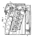
- an image forming apparatus embodying the present invention and mainly directed toward the first object stated earlier is shown and implemented as an electrophotographic printer by way of example.
- the printer includes four photoconductive drums or image carriers 1Y (yellow), 1C (cyan), 1M (magenta) and 1K (black), which may be replaced with photoconductive belts, if desired.
- the drums 1Y through 1K rotate in a direction indicated by arrows while contacting an intermediate image transfer belt (simply belt hereinafter) 10.
- the drums 1Y through 1K each is made up of a hollow, cylindrical conductive base having relatively small wall thickness, a photoconductive layer formed on the base, and a protection layer formed on the photoconductive layer.
- each drum has an outside diameter of 30 mm and an inside diameter of 28.5 mm.
- An intermediate layer may be formed between the photoconductive layer and the protection layer, if desired.
- the photoconductive layer may be implemented by an OPC (Organic PhotoConductor) in order to reduce cost, enhance free design, and obviate environmental pollution.
- OPC Organic PhotoConductor
- Polyvinyl carbazole or similar photoconductive resin is a typical OPC.
- OPCs are generally classified into PVK-TNF (2,4,7-trinitrofluorenone) and other charge transfer complex type of OPCs, phthalocyanine binder and other pigment dispersion type of OPCs, split-function type of OPCs each consisting of a charge generating substance and a charge transporting substance. Among them, split-function type of OPCs are attracting increasing attention today.
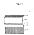
- FIG. 2 is a section showing the structure of any one of the drums 1Y through 1K used in the illustrative embodiment.
- the drum labeled 1
- the drum is a split-function type of photoconductive element and made up of a conductive base 51, a charge generating layer 52 formed on the base 51, a charge transporting layer 53 formed on the charge generating layer 52, and a protection layer 54 formed on the charge transporting layer 53.
- a latent image is formed on the drum 1 by the following mechanism.
- Such a split-function type of photoconductor should preferably be the combination of a charge transporting substance absorbing mainly ultraviolet rays and a charge transporting substance absorbing mainly visible rays.
- the problem with an OPC is that it lacks mechanical and chemical durability. More specifically, while many of charge transporting substances are developed as low molecular weight compounds, the compounds each are usually dispersed in or mixed with an inactive polymer because it cannot form a film alone. Generally, a low molecular weight compound or charge transporting substance and a charge transporting layer, which is implemented by an inactive polymer, are soft and lack mechanical durability. Therefore, when the drum 1 with the charge transporting layer is repeatedly used, the layer is easily shaved by the developer, belt 10 and a brush roller 41. It is therefore preferable to form the protection layer 54 in order to extend the life of the drum 1.
- Materials applicable to the protective layer 54 include ABS resin, ACS resin, olefine-vinylmonomer copolymer, chlorinated polyether resin, allyl resin, phenol resin, polyacetal resin, polyamide resin, polyamide-imide resin, polyacrylate resin, polyallyl sulfonic resin, polybutylene resin, polybutylene terephthalate resin, polycarbonate resin, polyether sulfonic resin, polyethylene resin, polyethylene terephthalate resin, polyimide resin, acrylic resin, polymethylpentene resin, polypropylene resin, polyphenyleneoxide resin, polysulfonic resin, AS resin, AB resin, BS resin, polyurethane resin, polyvinyl chloride resin, polyvinyliden chloride resin, and epoxy resin.
- a filler may be added to the protection layer 54 for improving abrasion resistance.
- the filler may be any one of polytetrafluoroethylene or similar fluorocarbon resin or silicone resin with or without titanium oxide, tin oxide, potassium titanate, silica, alumina or similar inorganic material being dispersed therein.
- the content of the filler should be 10 wt. % to 40wt. %, more preferably 20 wt.% to 30wt.%.
- a filler content less than 10 wt.% is apt to make abrasion resistance short, depending on arrangements around the drum 1 relating to the shaving of the drum 1.
- a filler content higher than 40 wt.% is apt to lower sensitivity to exposure.
- a dispersion aid may be added for improving the dispersiveness of the filler, if desired.
- the dispersion aid use may be made of any one of dispersion aids customary with, e.g., paints.
- the amount of the dispersion aid should be 0.5 % or above, but 4.0 % or below, of the filler content or above in terms of weight, preferably 1 % or above, but 2 % or below.
- Addition of a charge transporting material to the protective layer 54 is also effective.
- An antioxidant may also be added, if necessary.
- the thickness of the protection layer is between 0.5 ⁇ m and 10 ⁇ m, preferably between 4 ⁇ m and 6 ⁇ m.
- the intermediate layer which may be formed between the photoconductive layer made up of the charge generating layer 52 and charge transporting layer 53 and the protection layer 54, consists mainly of binder resin.
- the binder resin may be any one of polyamide, alcohol-soluble nylon, water-soluble polyvinyl butyral, polyvinylbutyral, polyvinyl alcohol, and so forth. Any one of conventional coating methods may be used to form the intermediate layer.
- the thickness of the intermediate layer should preferably be between 0.05 ⁇ m and 2 ⁇ m.
- FIG. 3 shows arrangements around the drum 1. It is to be noted that arrangements around the drums 1Y through 1K are identical with each other and distinguished from each other by suffices Y through K. As shown, a toner holding device or temporary toner holding means 40, a charging device or charging means 3 and a developing device or developing means 5 are sequentially arranged around the drum 1 in this order in the direction in which the surface of the drum 1 moves. A space for allowing a light beam, issuing from the exposing unit or latent image forming means 4 and represented by an arrow, to pass exists between the charging device 3 and the developing device 5.
- the charging device 3 uniformly charges the surface of the drum 1 to negative polarity.
- the charging device 3 includes a charge roller or charging member 3a that performs contact or vicinity type of charging. More specifically, the charge roller 3a contacts or adjoins the surface of the drum 1 and applied with a negative bias for uniformly charging the drum 1.
- a DC bias is applied to the drum 1 such that the surface of the drum 1 is uniformly charged to -500 V.
- the DC bias may be replaced with an AC-biased DC bias, if desired.
- the AC-biased DC bias however, needs an exclusive AC power supply and therefore makes the apparatus bulky.
- the charging device 3 additionally includes a cleaning brush 3b for cleaning the surface of the charge roller 3a.
- a cleaning brush 3b for cleaning the surface of the charge roller 3a.
- toner deposits on the charge roller 3a little, as will be described later specifically. However, any toner deposited on the charge roller 3a would bring about irregular charging or similar defective charging. This is why the cleaning brush 3b cleans the surface of the charge roller 3a.
- thin films may be wrapped around the axially opposite end portions of the charge roller 3a and held in contact with the drum 1.
- the surface of the charge roller 3a is extremely close to the surface of the drum 1, but spaced by the thickness of the films.
- the bias applied to the charge roller 3a causes discharge to occur between the charge roller 3a and the drum 1 for thereby uniformly charging the drum 1.
- the exposing unit 4 scans the charged surface of the drum 1 with a light beam in accordance with color-by-color image data, thereby sequentially forming latent images of different colors on the drum 1. While the exposing unit 4 uses a laser in the illustrative embodiment, use may alternatively be made of an exposing unit including an LED (Light Emitting Diode) array and focusing means.
- LED Light Emitting Diode
- the developing device 5 includes a casing accommodating a developing roller or developer carrier 5a.
- the developing roller 5a is partly exposed to the outside via an opening formed in the casing.
- the illustrative embodiment uses a two-component type developer made up of toner grains and carrier grains although it is similarly practicable with a single-component type developer, i.e., toner grains. More specifically, the developing device 5 stores toner replenished from corresponding one of toner bottles 31Y through 31K, which are individually removably mounted to the printer body. When any one of the toner bottles 31Y through 31K runs out of toner, it should only be replaced alone, successfully reducing running cost.
- the toner replenished from any one of the toner bottles 31Y through 31K to the developing device 5 is conveyed by a screw 5b while being agitated together with carrier grains and is then deposited on the developing roller 5a.
- the developing roller 5a is made up of a stationary magnet roller or magnetic field generating means and a sleeve rotatable about the axis of the magnet roller.
- the carrier grains of the developer are caused to rise on the sleeve in the form of brush chains by the magnetic force of the magnet roller and are conveyed by the sleeve to a developing zone where the sleeve and drum 1 face each other.
- the developing roller 5a rotates at a higher linear velocity than the drum 1.
- the brush chains on the developing roller 5a feed the toner grains deposited thereon to the drum 1 while rubbing the surface of the drum 1.
- a power supply applies a bias of -300 V for development to the developing roller 5a, forming an electric field in the developing zone.
- an electrostatic force directed toward the latent image on the drum 1, acts on the toner grains between the latent image and the developing roller 5a, causing the toner grains to deposit on the latent image and develop the latent image.
- the toner grains of expected or regular polarity, left on the drum 1 after the image transfer, are collected in the developing device 5.
- the belt 10 is passed over three rollers 11, 12 and 13 and caused to move in a direction indicated by an arrow in FIG. 1.
- Toner images of different colors are sequentially, electrostatically transferred from the drums 1Y through 1K to the belt 10 one above the other. While electrostatic image transfer may be implemented by a charger, the illustrative embodiment uses image transfer rollers 14Y through 14K because they reduce toner scattering.
- the image transfer rollers or primary image transferring means 14Y through 14K are held in contact with the inner surface of the loop of the belt 10 while facing the drums 1Y through 1K, respectively.
- the portions of the belt 10 pressed by the image transfer rollers 14Y through 14K and drums 1Y through 1K form nips for primary image transfer.
- a positive bias is applied to each of the image transfer rollers 14Y through 14K when a toner image is to be transferred from associated one of the drums 1Y through 1K tot he belt 10.
- an electric field for image transfer is formed in each nip and electrostatically transfers the toner image from the drum to the belt 10.
- a belt cleaner 10 adjoins the belt 10 for removing the toner left on the belt 10 and includes a fur brush and a cleaning blade.
- the fur brush and cleaning blade collect the toner left on the belt 10 after image transfer.
- the toner thus collected is conveyed from the belt cleaner 15 to a waste toner tank, not shown, by conveying means not shown.
- a secondary image transfer roller 16 is held in contact with part of the belt 10 passed over the roller 13, forming a nip for secondary image transfer therebetween.
- a sheet or recording medium is fed from a sheet cassette 20 to the above nip by a pickup roller 21 and a roller pair 22 at preselected timing.
- a composite toner image formed on the belt 10 is transferred from the belt 10 to the sheet at the nip for secondary image transfer. More specifically, a positive bias is applied to the secondary image transfer roller 16, forming an electric field for transferring the toner image from the belt 10 to the sheet.
- a fixing unit or fixing means 23 is positioned downstream of the secondary image transfer nip in the direction of sheet conveyance.
- the fixing unit 23 includes a heat roller 23, which accommodates a heater therein, and a press roller pressed against the heat roller 23.
- the heat roller 23 and press roller 23 nip the sheet and fix the toner image on the sheet with heat and pressure.
- the sheet with the toner image thus fixed is driven out to a stack tray positioned on the top of the printer body by an outlet roller pair 24.
- the drums 1Y through 1K, developing devices and other parts arranged around the drums 1Y through 1K, exposing unit 4, belt 10 and belt cleaning device 15 are constructed into a single process cartridge 30, which is removably mounted to the printer body.
- the process cartridge 30 can therefore be replaced when the life of any one of constituents thereof ends or the constituent needs maintenance.
- the toner bottles 31Y through 31K each are removable from the printer body independently of the process cartridge 30.
- the toner grains left on the drum 1 after image transfer contain toner grains charged to the regular or expected polarity and toner grains charged to the opposite polarity.
- the contact or vicinity type of charging system is applied to an image forming apparatus of the type uniformly charging the drum 1 to the same polarity as the toner, i.e., regular polarity.
- the toner grains of opposite polarity electrostatically deposit on the charge roller 3a and obstruct the uniform charging of the drum 1, resulting in the degradation of image quality stated earlier.
- the toner grains of regular polarity which is identical with the polarity of the bias applied to the charge roller 3a, do not deposit on the charge roller 3a. Moreover, the toner grains of regular polarity deposit on the carrier grains present on the developing roller 5a and are collected thereby or constitute the toner image in the image forming step. These toner grains therefore have little influence on the image forming step.
- FIG. 4A is a graph showing the charge potential distribution of the toner grains just before the transfer from the drum 1.
- FIG. 4B is a graph showing the charge potential distribution of the toner grains left on the drum 1 after the transfer from the drum 1.
- the amount of charge just before the transfer is distributed at both sides of substantially -30 ⁇ C/g; most of the toner grains are charged to negative or regular polarity.
- the amount of charge left on the drum 1 after the transfer is distributed at both sides of substantially -2 ⁇ C/g.
- most of the toner grains left on the drum 1 after the transfer are defective grains unable to be charged to the expected polarity due to, e.g., defective composition.
- toner grains of opposite polarity exist, as indicated by a hatched portion in FIG. 4B.
- the toner grains of opposite polarity are conveyed by the drum 1 to the position where the drum 1 faces the charge roller 3a, which is applied with the positive bias, then they are electrostatically attracted by and deposited on the charge roller 3a. This is also true with the configuration in which the charge roller 3a adjoins the drum 1 as stated above.
- the toner grains so deposited on the charge roller 3a cause the resistance and surface condition of the charge roller 3a to vary, so that charge start voltage between the charge roller 3a and the drum 1 becomes irregular.
- the drum 1 cannot be uniformly charged to the desired potential of -500 V. This is apt to bring about irregular image density as well.
- the toner grains deposit on only part of the charge roller 3a, then the current derived from the charge bias concentrates on the other part of the charge roller 3a where such toner grains are absent. Therefore, if the same bias as when the toner grains of opposite polarity are absent is applied, then the charge potential of the drum 1 rises above the desired potential. Consequently, the potential of the latent image portion, which is formed by the exposing unit 4, is shifted to the negative side, lowering image density.
- the charging ability of the charge roller 3a is lowered with the result that the surface potential of the drum 1 is lowered below the desired potential. consequently, the potential of the portion of the drum 1 not scanned by the exposing unit 4, i.e., the background portion approaches the bias applied to the developing roller 5a. This causes toner grains with short charge to deposit on the background of the drum, thereby bringing about background contamination.
- the residual toner grains on the drum 1 contain toner grains of negative or regular polarity as well.
- Such negative toner grains do not deposit on the charge roller 3a even when conveyed to the position where the charge roller 3a and drum 1 face each other so long as the bias is applied to the charge roller 3a.
- such toner grains have little influence on the image forming step, as stated previously. It is therefore important to prevent the toner grains of opposite polarity, existing in the residual toner grains, from adversely effecting the image forming step.
- the illustrative embodiment removes, before the residual toner on the drum 1 reaches the position where the drum 1 and charge roller 3a face each other, the toner of negative polarity with the temporary holding means.
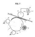
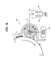
- the toner holding device 40 includes a brush roller 41 held in contact with the drum 1.
- the brush roller 41 is provided with relatively low brush density so as to have a space large enough to accommodate toner grains of opposite polarity T 1 . This not only reduces the frequency of release of the toner grains T 1 , which will be described later, but also reduces mechanical restraint to act on the toner grains T 1 held by the brush roller 41 for thereby promoting smooth release of the toner grains T 1 .
- density around the surface of the brush roller 41 is selected to be between 12,000 bristles/inch 2 and 858, 000 bristles/inch 2 .
- the bristles are 3 mm long, as measured from the shaft of the brush roller 41, and provided with a Young's modulus of 30 cN/dtex.
- a drive source 42 causes the brush roller 41 to rotate in a direction indicated by an arrow in FIG. 5.
- a first and a second power supply 43 and 44 selectively apply a bias to the brush roller 41 via a switch 45.
- the switch 45 is controlled by a controller, not shown, included in the illustrative embodiment.
- the first and second power supplies 43 and 44 respectively apply a hold bias that deposits a potential of -700 V on the brush roller 41 and a release bias that deposits a potential of +200 V on the same.
- the hold bias causes the brush roller 41 to hold the toner grains of opposite polarity T 1 while the release bias causes the former to release the latter.
- the power supplies 43 and 44 are implemented as DC power supplies in the illustrative embodiment, they may alternatively be implemented as AC-biased DC power supplies, if desired.
- the first power supply 43 starts applying the hold bias to the brush roller 41 via the switch 45.
- the brush roller 41 causes the toner grains of opposite polarity T 1 to deposit on the brush roller 41 for thereby holding them.
- the drum 1, uniformly charged to - 500 V by the charging device 3, is scanned by the exposing unit 4 with the result that the potential of the latent image portion is varied to about -50 V.
- the potential of the latent image portion is brought closer to 0 V.
- Most of the residual toner grains on the drum 1 are present in the portion where the latent image was present. Therefore, in the brush contact zone, the toner grains T 1 present on such a portion of the drum 1 are subject to an electrostatic force extending toward the brush roller 41, which is applied with the bias of -700 V.
- the background portion of the drum 1 where the potential is -500 V is also subject to the image transferring step, so that the potential is shifted toward the 0 V side. While a small amount of residual toner sometimes deposits on the background portion, the above electrostatic force acts on such toner grains T 1 also. Consequently, the toner grains T 1 , included in the residual toner grains on the drum 1, are deposited on and held by the brush roller in the brush contact zone.
- the toner grains of negative or regular polarity T 0 also included in the residual toner grains on the drum 1, are subject to an electrostatic force extending toward the drum 1 in the brush contact zone.
- the toner grains T 0 therefore remain on the drum 1 without being transferred to the brush roller 41.
- the toner grains T 0 conveyed via the brush contact zone by the drum 1, do not adversely effect the image transferring step, as stated earlier, but simply form the next toner image or are collected by the developing device 5.
- the brush roller 41 is rotated in the opposite direction to the drum 1, i . e. , in the counter direction in the brush contact region, so that a number of bristles can rub the surface of the drum 1 with their tips. Because the illustrative embodiment uses spherical toner grains, filming is likely to occur due to aging although the amount of residual toner is relatively small because of high image transfer efficiency. In the illustrative embodiment, the brush roller 41 rubs the surface of the drum 1 to thereby scatter the toner grains T 0 of regular polarity present on the drum 1. This successfully weakens the adhesion of the toner grains T 0 to the drum 1 and therefore promotes easy collection of the toner grains T 0 moved away from the brush contact zone by the developing device 5.
- a cleaning blade contacting the drum 1 is absent. This further reduces the load torque to act on the drive source assigned to the drum 1. Although the absence of a cleaning blade may lower the cleaning ability and bring about filming, the illustrative embodiment obviates filming by allowing the developing device 5 to efficiently collect the toner grains T 0 , as stated previously.
- the tips of the bristles, constituting the brush roller 41 jump up when they part from the surface of the drum 1 and are therefor likely to scatter the toner grains . If the brush roller 41 is moved in the same direction as the drum 1 in the brush contact zone, then the toner grains so scattered fly toward the downstream side of the brush contact zone in the direction of movement of the drum 1. Should such toner grains be of opposite polarity, then they would deposit on the charge roller 3a and bring about defective charging. By contrast, when the brush roller 41 is moved in the counter direction as in the illustrative embodiment, the toner grains scattered fly toward the upstream side of the brush contact zone in the direction of movement of the drum 1 and do not deposit on the charge roller 3a.
- the illustrative embodiment makes it needless to assign an exclusive cleaning device to each of the drums 1Y through 1K.
- This coupled with the fact that the toner holding device 40 has only to temporarily hold the toner grains of opposite polarity T 1 , makes the cleaning device far smaller in size than the conventional cleaning device.
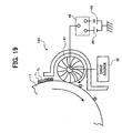
- the brush roller 41 is caused to release the toner grains T1 to the surface of the drum 1.
- the brush roller 41 holding the toner grains of opposite polarity T 1 , releases or returns them to the surface of the drum 1 at a preselected time when image formation is not under way. While this timing is open to choice, the release of the toner grains T 1 may be effected one time for every fifty times of image formation.
- the brush roller 41 releases them before part of the drum 1 to be uniformly charged by the charging device 3 during the next image forming step arrives at the brush contact zone. This allows the toner grains T 1 to be collected by the developing device 5 without adversely effecting the next image forming step. It is to be noted that in a repeat print mode, the brush roller 41 may release the toner grains T 1 consecutively deposited thereon after the last image forming step, in which case the image forming time is prevented from extending due to the collection of the toner grains T 1 to be described later.
- the release of the toner grains T 1 will be described more specifically hereinafter.
- the potential left after the preceding image forming step exists on part of the surface of the drum 1 to which the toner grains T 1 are expected to deposit at the timing stated above.
- the residual potential is about -50 V.
- the second power supply 44 applies the release bias to the brush roller 41 via the switch 45, the potential of +200 V is deposited on the brush roller 41 with the result that an electrostatic force, directed toward the drum 1 whose surface potential is -50 V, acts on the toner grains T 1 . Consequently, the toner grains T 1 are released from the brush roller 41 and deposited on the drum 1.
- the controller plays the role of bias interrupting means.
- the charge roller 3a is grounded with the result that the surface potential of the charge roller 3a becomes substantially 0 V.
- an electrostatic force directed toward the drum 1, acts on the toner grains T 1 at the contact position of the drum 1 and charge roller 3a. Consequently, the toner grains T 1 can pass the contact position without depositing on the charge roller 3a.
- the charging device 3 should preferably be provided with releasing means for selectively releasing the charge roller 3a from the drum 1, as will be described with reference to FIG. 6.
- a releasing mechanism or releasing means 30 is configured to release the charge roller 3a from the drum 1 before the toner grains T 1 , transferred from the brush roller 41 to the drum 1, reaches the position where they contact the charge roller 3a .
- the releasing mechanism 30 may have any one of conventional configurations. When the charge roller 3a is released from the drum 1, the toner grains T 1 can pass the position where they face the charge roller 3a without contacting or depositing on the charge roller 3a. This obviates the variation of the charge start voltage between the charge roller 3a and the drum 1 that would lower image density, bring about background contamination or irregular image quality.
- the toner grains T 1 moved away from the position where they contact the charge roller 3a are conveyed to the developing zone.
- the illustrative embodiment interrupts the application of the bias to the developing roller 5a as well before the toner grains T 1 on the drum reach the developing zone.
- the developing roller 5a is grounded with the result that the surface potential of the developing roller 5a becomes substantially 0 V.
- the surface potential of the drum 1 on which the toner grains T 1 are present is about -50 V, as stated previously, an electrostatic force, directed toward the drum 1, acts on the toner grains T 1 in the developing zone. Consequently, the toner grains T 1 can pass the developing zone without depositing on the developing roller 5a.
- the toner grains T 1 moved away from the developing zone are conveyed to the primary image transfer nip where they contact the belt 10.
- the illustrative embodiment applies a bias opposite in polarity to the bias for image formation to the primary image transfer roller 14 before the toner grains T 1 on the drum 1 arrive at the primary image transfer nip.
- a first and a second image transfer power supply 117 and 118 selectively apply a bias to the primary image transfer roller 14 via a switch 119 under the control of the controller.
- the first power supply 117 applies a bias of -300 V while the second power supply 118 applies a bias that differs from one of the primary image transfer rollers 14Y through 14K to another and lies in the range of from +400 V to +2,000 V.
- the second power supply 118 is connected to the primary image transfer roller 14 in the event of image transfer while the first power supply 118 is connected to the same in the event of collection of the toner grains T 1 from the drum 1.
- the negative bias applied to the primary image transfer roller 14 in the event of collection, forms an electric field between the surface of the drum 1 (-50 V) on which the toner grains T 1 are present and the belt 10.
- the electric field causes an electrostatic force directed toward the belt 10 to act on the tone grains T 1 , thereby transferring the toner grains T 1 from the drum 1 to the belt 10.
- the toner grains on the belt 10 are conveyed to the secondary image transfer nip between the belt 10 and the secondary image transfer roller 16.
- the bias for image transfer for usual image transfer i.e., a positive bias is applied to the secondary image transfer roller 16.
- the surface potential of the belt 10, carrying the toner grains T 1 is substantially 0 V at the nip, an electrostatic force, directed toward the belt 10, acts on the toner grains T 1 at the nip. Consequently, the toner grains T 1 are allowed to pass the nip without depositing on the secondary image transfer roller 16.
- the secondary image transfer roller 16 may be released from the belt 10.
- the toner grains T 1 thus moved away from the secondary image transfer nip are conveyed to a cleaning zone where they face the belt cleaner 15.
- the toner grains T 1 are scattered by the fur brush and then scraped off by the cleaning blade. In this manner, the toner grains T 1 on the belt 10 are collected by the belt cleaner 15.
- the illustrative embodiment causes the belt cleaner 15 to collect the toner grains T 1 from the belt 10, as stated above.
- a bias opposite in polarity to the bias assigned image formation may be applied to the secondary image transfer roller 16 so as to cause the roller 16 to collect the toner grains T 1 .
- This alternative arrangement needs cleaning means for cleaning the surface of the secondary image transfer roller. Further, the toner grains T 1 may be collected by the sheet.
- the toner grains T 1 released from the brush roller 41 are collected by way of the belt 10. This makes it needless to provide a waste toner tank for storing the toner grains T 1 for thereby implementing size reduction.
- the illustrative embodiment is a tandem printer including four drums 1Y through 1K, the size reduction is noticeable, compared to the conventional printer in which a particular waste toner tank is assigned to each drum.
- the developing device 5 may be so configured as to collect the toner grains T 1 , as will be described hereinafter.
- a bias identical with the bias for image formation i.e., -300 V is applied to the developing roller 5a, which plays the role of collecting means.
- an electrostatic force directed toward the developing roller 5a, acts on the toner grains T 1 between the drum 1 (-50 V) and the developing roller 5a, causing the toner grains T 1 to deposit on the developing roller 5a.
- the toner grains T 1 are conveyed to the inside of the developing device 5 by the developing roller 5a.
- the toner grains T 1 are then agitated in the developing device 5 and thereby charged to the regular polarity and again contribute to development.
- the toner grains T 1 may be collected by both of the belt 10 and developing device 5, so that part of the toner grains T 1 , moved away from the developing zone without being collected by the developing device 5, can be collected by the belt 10 at the primary image transfer nip. This further enhances sure collection of the toner grains T 1 .
- the toner grains T 1 can be sufficiently collected. Consequently, the frequency of release of the toner grains T 1 from the brush roller 41 can be reduced.
- the toner grains of regular or negative polarity may be collected by either one of the developing device 5 and belt 10 by any conventional technology.
- the illustrative embodiment lacking a cleaning blade for the drum 1, cannot easily collect the toner grains T 1 from the drum 1.
- the toner grains T 1 are transferred to the belt 10 in the same manner as during usual image formation and then collected by the belt cleaner 15.
- the belt cleaner 15 can collect even a large amount of toner grains T 1 because it includes the fur brush and cleaning blade. Part of the toner grains T 1 , which may be left on the drum 1 even after the transfer to the belt 10, are dealt with in the same manner as during usual image formation.
- the toner applicable to the illustrative embodiment will be described hereinafter.
- the removal of toner grains of opposite polarity unique to the illustrative embodiment uses the polarity of the toner before removal while the polarity of the toner depends mainly on frictional chargeabililty. It is therefore possible to enhance efficient image transfer and reduce the amount of residual toner by sharply control the distribution of the amounts of frictional charge of toner. Further, it is possible to lower the ratio of the toner grains of opposite polarity to the entire toner grains before removal and therefore to insure stable removal even when the amount of such undesirable toner grains is large.
- the toner grains applicable to the illustrative embodiment may be made up of mother grains, which consist of binder resin, a colorant, a charge control agent, organic fine grains and a parting agent and additives coated on the surfaces of the mother grains.
- mother grains consist of binder resin, a colorant, a charge control agent, organic fine grains and a parting agent and additives coated on the surfaces of the mother grains.
- the charge control agent and organic fine grains which have polarity, exist on the surfaces of the mother grains, so that the charge distribution of toner can be made sharp.
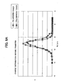
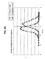
- FIGS. 8A and 8B respectively show the variation of charge amount distributions of polymerized toner applied to the illustrative embodiment and conventional pulverized toner determined under the application of a bias for image transfer.
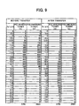
- FIG. 9 compare the polymerized toner and conventional pulverized toner in terms of specific numerical values derived from experiments.
- the polymerized toner applied to the illustrative embodiment is smaller in potential difference between toner grains ascribable to frictional charging than the pulverized toner and therefore makes the charge distribution sharper and chargeability more stable.
- the ratio of a weight M present on the surfaces of mother grains to a weight T present over the entire toner grains i.e., M/T is between 100 and 1, 000.
- This weight ratio M/T is a value measured by an XPS (X-ray Photoelectron Spectrum) method with one of elements up to the fifth period in the long form of the periodic table other than H, C, O and rare-gas elements, the elements up to the fifth period exist in the charge control agent, but do not exist in the other components of the toner.
- the binder resin is implemented by polyester having a lower grass transition temperature Tg, providing the toner with high low-temperature fixability.
- the charge control agent existing mainly on the surfaces of the toner grains as indicated by the ratio M/T, provides the toner with stable chargeability.
- the inorganic fine grains added to the surfaces of the mother grains for enhancing fluidity and promoting charging, are apt to part from the mother grains due to repulsion acting between them and the charge control agent.
- the illustrative embodiment insures cleaning and therefore high image quality if the parting ratio of the inorganic fine grains is between 1.0 % and 20.0 %.
- the volume-mean grain size of the toner should preferably be between 3 ⁇ m and 8 ⁇ m; the smaller the grain size, the higher the image quality. A volume-mean grain size below 3 ⁇ m would make it difficult to form liquid drops while a volume-mean grain size above 8 ⁇ m would be inferior to the dry pulverized toner from the cost standpoint, as determined by experiments.
- the ratio of the volume-mean grain size Dv to the number-mean grain size Dn i.e., Dv/Dn should preferably be 1.25 or below, more preferably between 1.05 and 1.25, from the image quality standpoint.
- Dv/Dn should preferably be 1.25 or below, more preferably between 1.05 and 1.25, from the image quality standpoint.
- the polymerized toner grains are close to a true sphere each and have high mean circularity while the pulverized grains have low mean circularity due to random irregularity existing on the surface of the grains.
- toner grains with low mean circularity have a broad grain size distribution and are therefore noticeably irregular in the surface area of the individual grain.
- Such toner grains are therefore noticeably different from each other in the amount of charge deposited by agitation and frictional charging by a doctor when being conveyed in the form of a developer layer. Consequently, the charge distribution of the toner grains in the developer becomes too broad to be evenly subject to the electric field for image transfer on the drum.
- the polymerized tone grains with high mean circularity all can be controlled in configuration with high accuracy and have therefore a narrow grain size distribution. Consequently, the difference in the amount of frictional charge between the toner grains and therefore the toner charge distribution decreases. This successfully increases the image transfer ratio for thereby reducing the amount of toner grains to be left on the drum after image transfer.
- Toner grains desirably charged deposit on the latent image of the drum 1 with priority and consumed thereby.
- the ratio of toner grains not desirably charged to the entire toner grains in the developing device 5 increases. Therefore, in the case of the pulverized toner grains or similar toner grains having low mean circularity and therefore a broad charge distribution, toner grains undesirably charged are left in the developing device 5 in a large amount due to repeated use.
- Such toner grains fail to accurately deposit on the latent image of the drum 1 although they are subject to the electric field in the developing zone. Therefore, when the mean circularity is low, background contamination, irregularity in dots and other defects occur due to repeated use, lowering image quality.
- Toner spent which refers to the filming of toner grains on carrier grains, grows worse with the elapse of time. Toner spent obstructs the frictional charging of fresh toner grains replenished to the developing device 5 and is also considered to degrade image quality.
- the toner grains with high mean circularity and therefore narrow charge distribution applied to the illustrative embodiment contain a far smaller amount of toner grains of undesirable charge than the toner grains with low mean circularity.
- Such toner grains therefore cause a minimum of background contamination, irregularity in dots and other defects despite a long time of use.
- the high mean circularity reduces the area over which the toner grains contact carrier grains for thereby preventing toner spend from easily occurring, so that high image quality is insured over a long period of time.
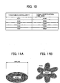
- the adequate value of mean circularity was determined by the following experiments. A developing device storing a developer was idled to determine a period of time in which toner spent was observed. FIG. 10 lists the results of experiments. When the mean circularity was 0.93 or above, toner spent was not observed at all even in 4,200 minutes corresponding to a period of time necessary for outputting 150,000 prints, which is generally used as a reference number of prints for estimation. The illustrative embodiment therefore uses toner grains having mean circularity of 0.93 or above.
- the mean circularity was determined by the following procedure using a flow type grain image analyzer FPIA-2100 (trade name) available from SYSMEX CORPORATION.
- a 1 % NaCl aqueous solution is prepared by using primary sodium chloride.
- the NaCl aqueous solution is then passed through a 0.45 filter in order to produce 40 ml to 100 ml of liquid.
- 0.1 ml to 5 ml of surfactant, preferably alkylbenzene solfonate is added to the above liquid, and then 1 mg to 10 mg of sample is added.
- the resulting mixture is dispersed for 1 minute in an ultrasonic dispersing device to thereby regulate the grain density to 5, 000 grains/ ⁇ l to 15, 000 grains/ ⁇ l.
- the liquid thus dispersed is picked up by a CCD (Charge Coupled Device) camera. Thereafter, the circumferential length of a circle identical in area with the area of the bidimensional projection image of the toner grain is divided by the circumferential length of the projection image of the toner grain, thereby producing circularity of the individual toner grain.
- CCD Charge Coupled Device
- the accuracy of the CCDs or pixels it was determined that a toner grain was acceptable if the diameter of the circle identical in area with the bidimensional projection image of the toner grain was 0 . 6 ⁇ m or above .
- the circularities of the acceptable toner grains are added and then divided by the number of toner grains to thereby produce mean circularity.
- the toner applicable to the illustrative embodiment may be produced by suspension polymerization that mixes a monomer, a starter, a colorant and so forth and then polymerizes, washes, dries and then executes postprocessing with the mixture.
- Suspension polymerization may be replaced with emulsion polymerization, bulk polymerization or solution polymerization, if desired.
- the circularity should preferably be between 100 and 180 in terms of shape coefficient SF-1 and between 100 and 190 in terms of shape coefficient SF-2.
- FIGS. 11A and 11B each show a specific configuration of a toner grain for describing the shape coefficients SF-1 and SF-2.
- the toner shape is truly spherical when SF-1 is 100 or becomes more amorphous with an increase in SF-1.
- the irregularity on the surface of the toner grain is zero when SF-2 is 100 or becomes more noticeable with an increase in SF-2.
- a toner grain was picked up by a scanning electron microscope S-800 (trade name) available from Hitachi, Ltd. and then input to an image analyzer LUSEX3 (trade name) available from NIREKO CO., LTD.
- the shape coefficients SF-1 and SF-2 both should preferably be 100 or above.
- SF-1 and SF-2 increase, the toner grains are scattered on an image to thereby lower image quality. Therefore, SF-1 and SF-2 should preferably do not exceed 180 and 190, respectively.
- Each toner grain should preferably be harder on the surface than in the side.
- the hardness of the entire toner grain can be determined by analyzing the components of the toner grain. Urea-bond polyester resin is harder when containing more nitrogen (N) atoms. This can be confirmed by measuring the composition distribution with the XPS method.
- each toner grain By hardening the surface of each toner grain, it is possible to obviate blocking even after a long time of use and to enhance fluidity of the toner grain for thereby promoting agitation and mixture. Further, the hard surface prevents the additives, coating the surface, from being buried in the surface, so that the fluidity and chargeability of the toner are maintained constant. Moreover, the low hardness of the inside of the toner grain allows the surface to be easily broken and deformed by heat and pressure in the event of fixation, so that the inside of the toner grain, containing the parting agent, can be exposed for enhancing fixability.
- the dyes and pigments include carbon black, Nigrosine dye, iron black, Naphthol Yellow S, Hansa Yellow(10G, 5G, G), Cadmium Yellow, yellow iron oxide, ocher, Chrome Yellow, Titanium Yellow, polyazo yellow, oil yellow, Hansa Yellow (GR, A, RN, R), Pigment Yellow L, Benzidine Yellow (G, GR), Permanent Yellow (NCG), Vulcan Fast Yellow (5G, R), Tartrazine Lake, Quinoline Yellow Lake, Anthrazane Yellow BGL, isoindolinone yellow, red oxide, minium, red lead, Cadmium Red, Cadmium Mercury Red, Antimony Red, Parmanent Red 4R, Para Red, Fire Red, p-chloro-o-nitroaniline red, Lithol Fast Scarlet G, Brilliant Fast Scarlet, Brilliant Carmine BS, Permanent Red (F2R, F4R, FRL, FRLL, F4RH), Fast Scarlet VD, V
- the colorant may be used as a master batch combined with a resin.
- Binder resin used for manufacturing the master batch or kneaded with the master batch may be any one of styrene polymer and polymer of substituents thereof, e.g., polystyrene, poly- p-chlorostyrene, and polyvinyltoluene, or copolymers of these with vinyl compounds, polymethyl methacrylate, polybutyl methacrylate, polyvinyl chloride, polyvinyl acetate, polyethylene, polypropylene, polyester, epoxy resin, epoxy polyol resin, polyurethane, polyamide, polyvinyl butyral, polyacrylic resin, rosin, modified rosin, terpene resin, aliphatic or alicyclic hydrocarbon resin, aromatic petroleum resin, chlorinated paraffin, and paraffin wax.
- Such binder resins may be used either singly or in combination.
- Polyester is produced by the condensation polymerization reaction of a polyhydric alcohol compound with a polyhydric carboxylic acid compound.
- the polyhydric alcohol compound (PO) use may be made of dihydric alcohol (DIO) or polyhydric alcohol (TO) higher than trihydric alcohol, preferably only DIO or a mixture of DIO with a small amount of ITO.
- dihydric alcohol there may be used any one of alkylene glycol (ethylene glycol, 1,2- propylene glycol, 1,3-propylene glycol, 1,4-butanediol, 1,6- hexanediol, etc.); alkylene ether glycol (diethylene glycol, triethylene glycol, dipropylene glycol, polyethylene glycol, polypropylene glycol, polytetramethylene ether glycol, etc.); alicyclic diol (1, 4-cyclohexane dimethanol, hydrogenated bisphenol A, etc.); bisphenols (bisphenol A, bisphenol F, bisphenol S, etc.); the above alicyclic diol added with alkylene oxide (ethylene oxide, propylene oxide, butylenes oxide, etc.); the above bisphenols added with alkylene oxide (ethylene oxide, propylene oxide, butylenes oxide, etc.).
- alkylene glycol ethylene glycol, 1,2- propylene glycol, 1,3-propylene glycol
- 2-12C alkylene glycol and bisphenols added with alkylene oxide are preferable, particularly bisphenols added with alkylene oxide, and this bisphenol jointly used with 2-12C alkylene glycol are preferable.
- polyhydric alcohol (TO) higher than trihydric alcohol polyhydric aliphatic alcohol of tri-octa hydric or higher (glycerol, trimethylol ethane, trimethylol propane, penta erythritol, sorbitol, etc.); trihydric or higher phenols (trisphenol PA, phenol novolak, cresol novolak, etc.); and the above trihydric or higher polyphenols added with alkylene oxide.
- Dihydric carboxylic acid (DIC) and trihydric or higher polyhydric carboxylic acid (TC) may be used as polyhydric carboxylic acid (PC); only DIC or a mixture of DIC with a small amount of TC is preferable.
- the dihydric carboxylic acid (DIC) any one of alkylene dicarboxylic acid (succinic acid, adipic acid, sebacic acid, etc.); alkenylendicarboxylic acid (maleic acid, fumaric acid,etc.); aromatic dicarboxylic acid (phthalic acid, isophthalic acid, terephthalic acid, naphthalenedicarboxylic acid, etc.) may be used.
- 4-20C alkenylenedicarboxylic acid and 8-20C aromatic dicarboxylic acid are preferable.
- trihydric or higher polyhydric carboxylic acid (TC) 9-20C aromatic plyhydric carboxylic acid (trimellitic acid, pyromellitic acid , etc.) may be used.
- Polyhydric carboxylic acid (PC) may be reacted with polyhydric alcohol (PO) using anhydride of the above substances or lower alkylester (methyl ester, ethyl ester, isopropyl ester, etc.).
- the ratio of polyhydric alcohol (PO) to polyhydric carboxylic acid (PC) is usually 2/1 to 1/1, preferably 1.5/1 to 1/1, more preferably 1.3/1 to 1.02/1, in terms of an equivalent ratio of a hydroxyl group (OR] / and a carboxylic group [COOH].
- PO and PC are heated to 150°C to 280°C in the presence of the known esterification catalyst, e.g., tetrabutoxy titanate or dibutyltineoxide.
- esterification catalyst e.g., tetrabutoxy titanate or dibutyltineoxide.
- the resulting water is distilled off with pressure being lowered, if necessary, to obtain polyester containing a hydroxyl group.
- the hydroxyl value of polyester is preferably 5 or above while the acid value of polyester is usually between 1 and 30, preferably between 5 and 20.
- polyester is easily negatively charged to improve the affinity of the toner with recording paper in fixing on a sheet.
- an acid value above 30 has adverse influence on stable charging, particularly on the environmental variation.
- a weight-mean molecular weight is between 10, 000 and 400,000, preferably, 20,000 and 200,000.
- a weight-mean molecular weight below 10,000 lowers offset resistance while a weight-mean molecular weight above 400,000 deteriorates low temperature fixability.
- Polyester preferably contains urea-modified polyester in addition to the above unmodified polyester produced by the condensation polymerization reaction.
- Urea-modified polyester is produced by reacting the carboxylic group or hydroxyl group at the terminal of polyester obtained by the above condensation polymerization reaction with a polyvalent isocyanate compound (PIC) to obtain polyester prepolymer (A) having an isocyanate group, and reacting it with amines to crosslink and/or extend the molecular chain
- PIC polyvalent isocyanate compound
- the polyvalent isocyanate compound (PIC) , us may be made of any one of aliphatic polyvalent isocyanate (tetra methylenediisocyanate, hexamethylenediisocyanate, 2,6- diisocyanate methyl caproate, etc.); alicyclic polyisocyanate (isophoronediisocyanate, cyclohexylmethane diisocyanate, etc.); aromatic diisocyanate (tolylenediisocyanate, diphenylmethene diisocyanate, etc.); aroma-aliphatic diisocyanate ( ⁇ , ⁇ , ⁇ ', ⁇ ',- tetramethylxylene diisocynate, etc.); isocaynates; the above isocyanats blocked with phenol derivatives, oxime, caprolactam, etc.; and a combination of two or more of them.
- aliphatic polyvalent isocyanate tetra methylenediiso
- the ratio of the polyvalent isocyanate compound (PIC) is usually 5/1 to 1/1, preferably 4/1 to 1.2/1 or more preferably 2.5/1 to 1.5/1, in terms of the equivalent ratio of an isocyanate group (NCO] /a hydroxyl group [OH] of polyester having the isocyanate group and the hydroxyl group.
- NCO isocyanate group
- a ratio [NCO] /OH higher than 5 would deteriorate low-temperature fixability.
- a molar ratio of NCO below than 1 if the urea-modified polyester is used, then the urea content in the ester is low, lowering the hot offset resistance.
- the content of the constitution component of the polyvalent isocyanate compound (PIC) in polyester prepolymer (A) having the isocyanate group is usually 0.5 wt.% to 40wt.%, preferably 1 wt.% to 30wt.% or more preferably 2 wt.% to 20wt.%.
- a content below 0.5wt.% deteriorates the hot offset resistance and causes disadvantageous compatibility of the heat resisting preservation property with the low temperature fixing property.
- a content higher than 40wt.% deteriorates the low temperature fixability.
- the number of isocyanate groups contained per molecule of polyester prepolymer (A) having the isocyanate group is usually more than one, preferably 1.5 to 3 in average or more preferably 1.8 to 2.5 in average. If the number of isocyanate groups is less than one per molecule, then the molecular weight of urea-modified polyester is low, deteriorating the hot offset resistance.
- amines (B) reacting with polyester prepolymer (A), there may be used any one of a divalent amine compound (B1), a polyvalent amine compound (B2) of trivalent or higher, amino alcohol (B3), aminomercaptan (B4), amino acid (B5), and a substance (6) with amino groups of B1-B5 blocked.
- divalent amine compound (B1) there may be used any one of aromatic diamine (phenylenediamine, diethyltoluenediamine, 4,4'-diamino diphenyl methane, etc.); alicyclic diamine (9,4'-diamino-3,3'- dimethyl dicyclohexylmethane, diamine cyclohexane, isophorone diamine, etc.); and aliphatic diamine (ethylene diamine, tetramethylene diamine, hexamethylene diamine, etc.) are listed.
- polyvalent amine compounds (B2) of trivalent or higher there may be used any one of diethylene triamine, triethylene tetramine, and so forth.
- amino alcohol (B3) ethanolamine, hydroxyethyl aniline or the like may be used.
- aminomercaptan (B4) use may be made of aminoethyl mercaptan, amino propylmercaptan or the like .
- amino acid (B5) use may be made of amino propionic acid, aminocaproic acid or the like.
- substances (B6) consisting of B1-B5 with their amino groups blocked use may be made of any one of a ketimine compound obtained from the above amines B1-B5 and ketones (acetone, methyl ethyl ketone, methyl isobutyl ketone, etc. ) , an oxazolidine compound, and so forth.
- preferable amines (B) are B1 and a mixture of B1 and a small amount of B2.
- the ratio of amines (B) is usually 1/2 to 2/1, preferablyl 1.5/1 to 1/1.5 or more preferably 1 . 2/1 to 1/1.2, in terms of the equivalent ratio of [NCO]/[NHx] of the isocyanate group [NCO] in polyester prepolymer (A) having the isocyanate group and the amino group [NHx] in amines (B).
- a ratio NCO/NHx above 2 or below 1/2 lowers the molecular weight of urea-modified polyester, deteriorating the hot offset resistant property
- a urethane bond, as well as a urea bond, may be contained in urea-modified polyester.
- a molar ratio of the urea bond content to the urethane bond content is usually 100/0 to 10/90, preferably 80/20 to 20/80 or more preferably 60/40 to 30/70.
- a molar ratio of the urea bond below10% deteriorates the hot offset resistance.
- Urea modified polyester is produced by, e.g., the one-shot method.
- Polyester having the hydroxyl group is produced by reacting polyhydric alcohol (PO) with polyhydric carboxylic acid (PC) , in the presence of a known esterification catalyst, e.g., tetrabutoxy titanate, dibutyltineoxide or the like, heating to 150°C to 280°C with pressure being reduced, if necessary, and distilling off the resulting water.
- a known esterification catalyst e.g., tetrabutoxy titanate, dibutyltineoxide or the like
- polyester prepolymer (A) having the isocyanate group is obtained.
- the prepolymer (A) is reacted with amines (B) at 0°C to 140°C to obtain urea-modified polyester
- a solvent may be used, if necessary.
- the solvent may be selected from any one of a group of solvents inactive to isocyanate (PIC), e.g., an aromatic solvent (toluene, xylene, etc.); ketones (acetone, methyl ethyl ketone, methyl isobutyl ketone, etc.); esters (ethyl acetate, etc.); amides (dimethyl formamide, dimethyl acetatamide, etc.); and ethers (tetrahydrofuran, etc.).
- PIC solvent inactive to isocyanate
- a reaction terminator may be used for the cross-linking reaction and/or extension reaction of polyester prepolymer (A) with amines (B), to control the molecular weight of obtained urea-modified polyester.
- the reaction terminating agents include monoamine (diethylamine, dibutylamine, butylamine, lauryl amine, etc.), and blocked substances thereof (a ketimine compound).
- the weight-mean molecular weight of urea-modified polyester is usually 10,000 or above, preferably 20,000 to 10, 000, 000 or more preferably 30,000 to 1,000,000. A molecular weight of less than 10, 000 deteriorates the hot offset resisting property.
- the number-mean molecular weight of urea-modified polyester or the like is not limited when the above unmodified polyester is used, but the number-mean molecular weight that allows the above weight-mean molecular weight to be attained is acceptable. In the case where urea-modified polyester is used in a single form, its number-mean molecular weight is 2, 000 to 15,000, preferably 2,000 to 10,000 or more preferably 2,000 to 8,000. A molecular weight higher than 20,000 deteriorates the low temperature fixability and luster when urea- modified polyester is used in a full-color image forming apparatus.
- unmodified polyester and urea-modified polyester in combination, it is possible to improve low-temperature fixability and, when a full-color apparatus is used, luster. In this sense, the above combination is more preferable than only urea-modified polyester. It is to be noted that unmodified polyester may contain polyester modified by a chemical bond other than the urea bond.
- Unmodified polyester and urea-modified polyester should desirably be at least partly in a compatible state from the low temperature fixability and hot offset resistance standpoint. Therefore, unmodified polyester and urea-modified polyester should preferably have a similar composition.
- the weight ratio of unmodified polyester to urea-modified polyester is usually 20/80 to 95/5, preferably 70/30 to 95/5 or more preferably 75/25 to 95/5 or even more preferably 80/20 to 93/7.
- a weight ratio of urea-modified polyester below 5% deteriorates the hot offset and causes disadvantageous compatibility of the heat resisting preserving property and low temperature fixability.
- the glass transition temperature Tg of the binder resin containing unmodified polyester and urea-modified polyester is usually 45°C to 65°C, preferably 45°C to 60°C. Glass transition temperature below 45°C deteriorates the heat resisting property of the toner while a temperature higher than 65°C makes the low temperature fixing property short. Because urea-modified polyester is apt to exist on the surfaces of the mother grains, it exhibits a more desirable heat resisting preserving property than the conventional polyester-based toner grains even if glass transition temperature is low.
- any one of conventional colorless or monochrome agents that do not bring about color tone defects.
- any one of a quaternary ammonium chloride compound may be used while as for a negative charge type of agent, there may be used any conventional material, e.g., a metallic complex or metallic salt of chromium, zinc, aluminum, etc. of salicylic acid or alkylsalicylic acid, a metallic complex or metallic salt of benzilic acid, an amide compound, a phenol compound and a naphthol compound may be used either singly or in combination.
- At least one of the metallic complex or metallic salt of salicylic acid, an organic boron compound, an oxynaphthoic acid-based metallic complex or metallic salt and a fluorine-containing ammonium chloride compound is preferable. More specifically, a salicylic acid-based metallic complex E-84 (trade name) available from Orient Chemical Industries Co. Ltd., LR-147, a boron complex LR-147 (trade name) available from Japan Carlit Co. Ltd. or an oxynaphthoic acid-based metallic complex E-82 (trade name) also available from Orient Chemical Industries Co. Ltd. may be used.
- the amount of the charge control agent to be used is determined by the type of the binder resin, whether or not an additive is used or the toner producing method including the dispersion method and not unconditionally limited. However, charge control agent should preferably by used by 0.1 pts .wt to 10 pts.wt., preferably 0.2 pts.wt to 5 pts.wt., to 100 pts.wt. of the binder resin. An amount above 10 pts.wt. makes the chargeability of toner excessive and therefore reduces the effect of the main charge control agent while increasing electrostatic attraction with the developing roller. As a result, the fluidity of the developer and image density are lowered.
- Organic fine grains are added to stabilize the toner mother grains formed in an aqueous medium.
- at least one of vinyl resin, polyurethane resin, epoxy resin, silicone resin, polyester resin and fluororesin is preferably used.
- the organic fine grains may be 1 ⁇ m and 3 ⁇ m methyl polymethacrylate, 0.5 ⁇ m and 2 ⁇ m polystyrene, 1 ⁇ m poly(styrene-acrylonitrile) ; PB-200H (trade name) available from Kao Co. Ltd., SGP (trade) available from Soken Co. Ltd., Technopolymer SB (trade name) available from Sekisui Chemical Co. Ltd., SGP-3G (trade name) available from Soken Co. Ltd., Micropearl (trande name) available from Sekisui Fine Chemical Co. Ltd.) are examples available on the market.
- the above toner should preferably contain a parting agent, e . g. , wax having a melting point as low as 50°C to 120°C that acts more effectively between the heat roller and the toner than in the dispersion with the binder resin and thereby copes with high-temperature offset without resorting to oil or similar parting agent otherwise coated on the heat roller .
- the wax may be selected from any one of a group of vegetable waxes including carnauba wax, cotton wax, Japan wax, rice wax a group of animal waxes including beewax and lanolin; a group of mineral waxes including ozokerite and selsyn; and a group of petroleum waxes including paraffin, microcrystalline, and petrolatum.
- fatty amides including 12-hydroxyl stearic acid amide, stearic acid amide, phthalic anhydride imide, and chlorinated hydrocarbon, and crystalline polymers having long alkyl groups in side chains, including homopolymer of polyacrylate of poly-n-stearyl methacrylate and poly-n-lauryl methacrylate which are crystalline high polymer resins of low molecular weight or copolymers including a copolymer of n-stearyl acrylate with ethylmethacrylate) may also be used.
- the charge control agent and parting agent may be kneaded together with the master batch and binder resin or may, of course, be added when it is dissolved or dispersed in an organic solved.
- Inorganic fine grains should preferably be used for further promoting the fluidity, developing ability and charging ability of the toner grains.
- the primary grain size of the inorganic fine grains should preferably be 5 x 10 -3 to 2 ⁇ m, particularly 5 x 10 -3 ⁇ m to 0.5 ⁇ m.
- a specific area measured by a BET method should preferably be 20 m 2 /g to 500m 2 /g.
- the ratio of the inorganic grains to the entire toner grains should preferably be 0.01 wt. % to 5wt. %, more preferably 0.01 wt.% to 2.0wt.%. A ratio below 0.01wt.% brings about insufficient fluidity while a ratio above 5wt.% brings about easy separation of the external additive from the toner grains.
- the inorganic fine grains are silica, alumina, titanium oxide, barium titanate, magnesium titanate, calcium tiatanate, strontium titanate, zinc oxide, tin oxide, quartz sand, clay, mica, wollastonite, diatomaceous earth, chromium oxide, cerium oxide, red oxide, antimony trioxide, magnesium oxide, zirconium oxide, barium sulfate, barium carbonate, calcium carbonate, silicon carbide, and silicon nitride.
- hydrophobic silica fine grains and hydrophobic titanium oxide fine grains in combination it is preferable to use.
- the fluidity imparting agent does not part from the toner grains and insures desirable image quality free from spots or similar image defects. In addition, there can be reduced the amount of residual toner.
- Titanium oxide fine grains are desirable in environmental stability and image density stability, but tend to lower in charge start characteristics. Therefore, if the amount of titanium oxide fine particles is larger than the amount of silica fine grains, then the influence of the above side effect is considered to increase. However, so long as the amount of hydrophobic silica fine grains and hydrophobic titanium oxide fine grains is between 0.3 wt.% and 1.5 wt.%, the charge start characteristics are not noticeably impaired, i.e., desired charge start characteristics are achievable. Consequently, stable image quality is achievable despite repeated copying operation.
- a colorant, unmodified polyester, polyester prepolymer having isocyanate groups and a parting agent are dispersed into an organic solvent to prepare a toner material liquid.
- the organic solvent should preferably be volatile and have a boiling point of 100°C or below because such a solvent is easy to remove after the formation of the toner mother grains.
- toluene xylene
- benzene carbon tetrachloride
- methylene chloride 1,2-dichloroethane, 1,1,2-trichloroethane, trichloro ethylene
- chloroform monochlorobenzene, dichloroethylidene, methyl acetate, ethyl acetate, methyl ethyl ketone, methyl isobutyl ketone, and so forth.
- the aromatic solvent e.g., toluene or xylene or a hydrocarbon halide, e.g., methylene chloride, 1,2-dichloroethane, chloroform or carbon tetrachloride is desirable.
- the amount of the organic solvent to be used should preferably 0 pts.wt. to 300 pts.wt., more preferably 0 pts.wt. to 100 pts.wt. or even more preferably 25 pts.wt. to 70 pts.wt., for 100 pts.wt. of polyester prepolymer.
- the toner material liquid is emulsified in an aqueous medium in the presence of a surfactant and organic fine grains.
- the aqueous medium may be only water or water containing an organic solvent, e.g., alcohol (methanol, isopropyl alcohol, ethylene glycol, etc.), dimethylformamide, tetrahydrofuran, cellusolves (methyl cellusolve, etc.) or lower ketones (acetone, methyl ethyl ketone, etc.).
- the amount of the aqueous medium for 100pts.wt. of the toner material liquid is usually 50 pts.wt. to 2,000 pts.wt., preferably 100 pts.wt. to 1, 000pts.wt.
- An amount below 50 pts.wt. makes the dispersion state of the toner material liquid insufficient and thereby prevents the toner grains of the preselected grain size from being obtained.
- An amount above 2,000 pts.wt. is not desirable from the cost standpoint.
- the surfactant may be any one of an anionic surfactant, e.g., alkyl benzene sulfonate, a-olefin sulfonate, or ester phosphate; a cationic surfactant, e.g., an amine salt type like alkylamine salt, aminoalcohol fatty acid derivatives, polyamine fatty acid derivatives, imidazolin, and a quarternary ammonium salt type like alkyltrimethyl ammonium salt, dialkyldimethyl ammonium salt, alkyldimethylbenzil ammonium salt, pyridinium salt, alkyl isoquinolinium salt or benzetonium chloride; a non-ionic surfactant, e.g., an fatty acid amide derivative or a polhydric alcohol derivative; or an am
- a surfactant having a fluoroalkyl group improves the effect of the dispersant when added in an extremely small amount.
- Preferable anionic surfactants having fluoroalkyl groups include 2-10C fluoroalkylcarboxylic acid and its metallic salts, disodium perfluorooctane sulfonyl glutamate, sodium 3-[ ⁇ -(6-11C) fluoroalkyl oxy]-1-(3-4C)alkyl sulfonate, sodium 3-[ ⁇ -(6-8C) fluoroalkanoyl-N-ethylamino]-1-propanesulfonate, 11-20C fluoroalkyl carboxylic acid and its metallic salts, 7-13C perfluoroalkyl carboxylic acid and its metallic salts, 4-12C perfluoroalkyl sulfonic acid and its metallic salts, perfluorooctane sulfonic acid diethanolamide, N-propyl-N
- anionic surfactants the following products are available on the market, i.e., Surfron S-111, S-112 and S-113 (trade names) available from Asahi Glass Co. Ltd., Fluorad FC-93, FC-95, FC-98 and FC-129 (trande namers) available from Sumitomo 3M Co. Ltd., Unidyne DS-101, DS-102 (trade names) available from Daikin Industries Co. Ltd., Megafack F-110, F-120, F-113, F-191, F-812 and F-833 (trade names) also available from Dainippon Ink Co.
- Surfron S-111, S-112 and S-113 trade names
- Fluorad FC-93, FC-95, FC-98 and FC-129 trande namers
- Unidyne DS-101, DS-102 (trade names) available from Daikin Industries Co. Ltd.
- Ektop EF-102, 103, 104, 105, 112, 123A, 123B, 306A, 501, 201 and 204 (trade names) available from Tokem Products Co. Ltd., Phthargent F-100 and F-150 (trade names) available from Neos Co. Ltd.), and so forth.
- cationic surfactants there may be used any one of aliphatic primary, secondary or tertiary amic acid having fluoroalkyl groups; an aliphatic quaternary ammonium salt, e.g., 6-10C perfluoroalkyl sulfonamide propyltrimethyl ammonium salt or benzalkonium salt; benzetonium chloride, pyridinium salt or imidazolinium salt; or Surfron S-121 (trade name) available from Asahi Glass Co. Ltd., Fluorad FC-135 (trade name) available from Sumitomo 3M Co. Ltd., Unidyne DS-202 (trade name) available from Daikin Industries Co.
- an aliphatic quaternary ammonium salt e.g., 6-10C perfluoroalkyl sulfonamide propyltrimethyl ammonium salt or benzalkonium salt
- benzetonium chloride pyridinium salt or imid
- An inorganic compound dispersant e.g., tricalcium phosphate, calcium carbonate, titanium oxide, colloidal silica or hydroxyl apatite may also be used.
- dispersant droplets may be stabilized by high polymer-based protective colloid as a dispersant usable together with organic fine grains or inorganic compound dispersant.
- the protective colloid may be any one of acids, e.g., acrylic acid, methacrylic acid, ⁇ -cyanoacrylic acid, ⁇ -cyanomethacrylic acid, itaconic acid, crotonic acid, fumaric acid, maleic acid and maleic anhydride; (meth) acrylic monomers having a hydroxyl group, e.g., acrylic acid- ⁇ -hydroxyethyl, methacrylic acid- ⁇ -hydroxyethyl, acrylic acid- ⁇ -hydroxypropyl, methacrylic acid- ⁇ -hydroxypropyl, acrylic acid- ⁇ -hydroxypropyl, methacrylic acid- ⁇ -hydroxypropyl, acrylic acid-3-chloro-2-hydroxypropyl, methacrylic acid-3-chloro-2-hydroxypropyl, diethyleneglycol monoacrylic ester, diethyleneglycol mono
- vinyl acetate, vinyl propionate and vinyl butyrate acrylamide, methacrylamide, diacetone acrylamide and methylol compounds thereof; acid chlorides, e.g., chloride acrylate and chloride methacrylate; nitrogen-containing compounds, e.g., vinyl pyridine, vinyl pyrrolidone, vinyl imidazole and ethyleneimine; and homopolymers or copolymers of heterocyclic compounds thereof; polyoxyethylenic substances, e.g., polyoxyethylene, polyoxy propylene, polyoxyethylene alkylamine, polyoxypropylene alkylamine, polyoxyethylene alkylamide, polyoxypropylene alkylamide, polyoxyethylene nonylphenyl ether, polyoxiethylene laurylphenyl ether, polyoxyethylene stearylphenyl ester and polyoxyethylene nonylphenyl ester; and celluloses, e.g., methylcellulose, hydroxyl ethylcellulose and hydroxy
- the dispersion method may be implemented by any one of conventional dispersion facilities, e.g., a low speed shearing type, high speed shearing type, friction type, high pressure jet type and ultrasonic type .
- the high speed shearing type is preferable for implementing the dispersed grains with a grain size of 2 ⁇ m to 20 ⁇ m.
- the number of rotation of the high speed shearing type disperser is not limited, but is usually 1,000 rpm (revolutions per minute) to 30,000 rpm, preferably 5, 000 rpm to 20,000rpm.
- the dispersion time is not limited, it is usually 0.1 minute to 5 minutes for the batch system.
- a dispersion temperature is usually 0°C to 150°C, preferably 40°C to 98°C in a pressurized condition.
- amines (B) are added to the emulsion in order to cause the emulsion to react with the polyester prepolymer (A) having isocyanate groups.
- the reaction causes the crosslinking and/or extension of the molecular chains to occur.
- the reaction time is selected in accordance with the reactivity of the isocyanate group structure of the polyester prepolymer (A) with amines (B) and is usually 10 minutes to 40 hours, preferably 2 hours to 24 hours.
- a reaction temperature is usually 0°C to 150°C, preferably 40°C to 98°C.
- any conventional catalyst e.g., dibutyltinelaulate or dioctyltinelaulate, if necessary.
- the organic solvent is removed from the emulsified dispersed matter (reaction product), washed and then dried to obtain the toner mother grains.
- the entire system is gradually heated in a laminar-flow agitating state, strongly agitated in a preselected temperature range, and then subjected to solvent removal, so that fusiformtoner mother grains are produced.
- the dispersion stabilizer is implemented by, e.g., calcium phosphate, soluble in acid or alkali
- calcium phosphate is removed from the toner mother grains by dissolving calcium phosphate by hydrochloric acid or similar acid and washing with water. Further, use may be made of decomposition using an enzyme.
- the charge control agent is placed into the above toner mother grains, and then the inorganic fine grains are externally added to obtain the toner .
- the placing of the charge control agent and external addition of the inorganic fine grains may be performed by any conventional method using, e.g., a mixer.
- the illustrative embodiment is implemented as a cleaningless image forming apparatus, it is possible to effectively remove toner grains of opposite polarity and therefore obviate the variation of charge start voltage ascribable to the above toner grains .
- This not only obviates a decrease in image density, background contamination and irregularity in image density, but also reduces the size and cost of the apparatus.
- toner free from scattering and insuring a high image transfer ratio it is possible to enhance image quality.
- FIGS. 1 through 5 which show the first embodiment, directly apply to the second embodiment, the following description will concentrate only on differences between the first and second embodiments.
- a change in temperature or humidity causes the surface potential of the drum 1 uniformly charged by the charging device 3 to vary. Also, the amount of charge deposited on the toner by agitation in the developing device 5 varies, so that the amount of toner to deposit on the latent image of the drum 1 varies.
- the variation of the drum surface potential and that of the amount of toner to deposit on the latent image directly effect image quality. For example, when humidity is high, the amount of charge of toner decreases and causes the amount of toner to deposit on the latent image to increase, aggravating contamination ascribable to toner and thereby lowering image quality.
- bias control means that varies the charge bias, development bias or similar bias in accordance with temperature and humidity.
- the bias control means must deal with different portions susceptible to the variation of temperature and that of humidity one by one and therefore needs a sophisticated configuration. Moreover, it is extremely difficult for the bias control means to fully cope with the variation of temperature and that of humidity.
- the process cartridge 30 is provided with a substantially hermetic or air-tight configuration, so that the inside of the process cartridge 30 is isolated from the environment around the process cartridge 30.
- an air controller 32 is disposed in the process cartridge 30 for controlling the inside of the process cartridge 30. More specifically, the air controller 32 controls temperature and humidity inside the process cartridge 30 to preselected values. It is therefore not necessary to deal with different portions susceptible to the variation of temperature and that of humidity one by one. With this configuration, the illustrative embodiment can sufficiently protect image quality from degradation ascribable to temperature and humidity.
- either one of temperature and humidity inside the process cartridge 30 should only be controlled to a preselected value.
- the devices arranged in the process cartridge 30 may be confined in a highly air-tight case not removable from the printer body, in which case the air controller 32 will be disposed in the case. This is also successful to achieve the advantages stated above.
- Toner applied to the illustrative embodiment is produced by polymerization and consists of grains each having a shape close to a true circle and therefore smooth surface. Therefore, a difference between the toner grains as to the amount of toner to deposit is small. In this condition, as shown in FIG. 4A, the charge distribution of the toner grains is narrow enough to enhance efficient image transfer for thereby reducing the amount of residual toner to be left on the drum 1.
- the illustrative embodiment uses toner grains having mean circularity of 0.95 or above.
- Experiment 1 was conducted to estimate the appearance of black stripes in an image by varying the mean circularity of toner grains. More specifically, a test machine 1 configured to clean the drum 1 having the protection layer 54 with a blade and a test machine 2 configured to clean it without a blade were compared. Also, the test machine 2 and a test machine 3 configured to clean the drum 1, which lacked the protection layer 54, without a blade were compared. Further, the test machines 2 and 3 each were implemented by the printer of the illustrative embodiment while the test machine 1 was provided with a cleaning blade formed of rubber in place of the brush roller 41.
- FIG. 12 is a graph showing the results of Experiment 1. As shown, the result of estimation as to black stripes tends to become more favorable with an increase in the mean circularity of toner grains in all of the test machines 1 through 3. This is presumably accounted for by the following.
- toner grains on the scratches despite the absence of a latent image is presumably ascribable to an occurrence that while portions without the scratches are uniformly charged to -500 V by the charging device 5, portions with the scratches cause the potential to shift from -500 V toward the 0 V side due to defective charging.
- toner grains are mechanically captured by the scratches is presumably that toner grains, usually expected to deposit on the drum surface under the action of an electrostatic force of an electric field, are mechanically captured by the scratches when the developer enters the scratches.
- Experiment 1 presumably reduced black stripes ascribable to at least the mechanical capture because the mean circularity of toner grains was increased. More specifically, toner grains with high circularity and therefore smooth surfaces are not easily mechanically captured by the scratches, compared to toner grains produced by, e.g., pulverization and having uneven surfaces. Further, such circular toner grains, if captured by the scratches, can easily escape the scratches when the following part of the developer rubs the scratches.
- the highest black stripe rank 5 is achievable if the mean circularity of toner grains is 0.93 or above.
- black stripe rank 5 is not achievable unless the mean circularity of toner grains is 0.95 or above. It will therefore be seen that the blade type of test machine 1 has a greater margin as to black stripes than the bladeless type of test machine 2.
- Experiment 2 was conducted to determine a relation between the number of prints output and the shaving of the drum surface. More specifically, Experiment 2 was conducted with toner grains having the mean circularity of 0.95 and by using the three test machines as in Experiment 1. An image of size A4 landscape and having an image area ratio of 5 % was repeatedly printed. The amount of shaving of the drum surface was measured after 13,000 prints, 26,000 prints, 39,000 prints and 50,000 prints were output.
- FIG. 13 is a graph showing experimental results obtained with Experiment 2.
- the amount of shaving is acceptable in practice so long as it lies in a range below a dotted line shown in FIG. 13. As shown, the amount of shaving increases with an increase in the number of prints in all of the test machines 1 through 3.
- the bladeless type of test machine 3 dealing with the drum 1 lacking the protection layer 54, shaved the drum surface more than the bladeless type of test machine 2 dealing with the drum 1 having the protection layer 54 even when only a small number of prints were output. This is presumably because the protection layer 54, having higher hardness than the photoconductive layer, increased the durability of the drum surface against the rubbing of the brush roller 41.
- the blade type of test machine 1 shaved the drum surface more than the bladeless type of test machine 2 even when only a small number of prints were output. This is presumably because the brush roller 41 of the test machine 2 rubbed the drum surface with a weaker force than the blade of the test machine 1.
- the bladeless type of test machine 2 can therefore extend the life of the drum 1 more than the blade type of test machine 1.
- drum 1 included in the illustrative embodiment will be described hereinafter.
- a photoconductive drum was made up of a conductive base 151 formed of aluminum and having a diameter of 30 mm and a 3.5 ⁇ m thick under layer 155, a 0.2 ⁇ m thick charge generating layer 152, a 25 ⁇ m thick charge transporting layer 153 and a 5 ⁇ m thick protection layer 154 sequentially stacked on the base 151 by a procedure to be described hereinafter.
- the charge generating layer 152 To form the charge generating layer 152, 0-25pts.wt. of polyvinyl butyral, 200 pts.wt. of cyclohexanone, 2.25 pts.wt. of trisazo pigment represented by a formula shown in FIG. 15 and 80 pts .wt. of methyl ethyl ketone were mixed together to prepare a coating liquid. The coating liquid was then coated on the under layer 155 by dip coating and then dried for 20 minutes at 130°C to thereby form the 0.2 ⁇ m thick charge generating layer 152.
- charge transporting layer 153 100 pts.wt. of methylene chloride, 10 pts.wt. of bisphenol-A-polycarbonate and 10 pts.wt. of low molecular weight and charge transporting substance represented a formula shown in FIG. 16 were mixed together.
- the resulting coating solution was coated on the charge generating layer 152 by dip coating and then dried for 20 minutes at 110°C to thereby form the 25 ⁇ m thick charge transporting layer 153.
- protection layer 154 2 pts . wt . of charge transporting substance represented by a formula shown in FIG. 17, 4 pts.wt. of A-polycarbonate and 100 pts.wt. of methylene chloride were mixed together. The resulting coating liquid was coated on the charge transporting layer 153 by spray coating and then dried for 20 minutes at 110°C to thereby form the 5 ⁇ m thick protection layer 154.
- a photoconductive drum had the same structure as the photoconductive drum of Example 1 except for the protection layer 154.
- Example 2 to form the projection layer 154, 4 pts.wt. of charge transporting layer shown in FIG. 16, 4 pts.wt. of A-polycarbonate, 1 pts.wt. of titanium oxide serving as a filler and 100 pts.wt. of methylene chloride were mixed together. The resulting coating liquid was coated on the charge transporting layer 153 by spray coating and then dried for 20 minutes at 100°C to thereby form the protection layer 154 that was 2 ⁇ m thick.
- Example 3 is identical with Example 2 except that titanium oxide, playing the role of a filler, was replaced with aluminum oxide.
- the drums of Examples 1 through 3 each were mounted to a digital copier Imagio MF200 (trade name) available from RICOH CO., LTD. and subjected to continuous printing. Examples 1 through 3 all were determined to be excellent by total estimation including image density and resolution.
- An F/C ratio representative of the ratio of fluorine to carbon atoms present on the surface of the drum was 0.
- the F/C ratio is used as an index representative of the amount of deposition of a fluorine-based material present on the drum surface.
- the thickness of the photoconductive layer decreased little from the initial value and insured stable, high definition hard copies over a long period of time.
- the illustrative embodiment can reduce black stripes with a bladeless type of cleaning system as with a blade type of cleaning system and can therefore extend the life of the drum while sufficiently controlling black stripes.
- FIGS. 1 through 7 and 10 which show the first embodiment, directly apply to the third embodiment, the following description will concentrate only on differences between the first and third embodiments.
- the brush roller 41 of the illustrative embodiment has bristles thereof tilted beforehand such that their tips are directed in preselected directions, which are coincident with the direction in which the bristles yield. More specifically, in the illustrative embodiment, the drive source 42 causes the brush roller 41 to rotate in a direction indicated by an arrow in FIG. 18 such that the roots of the bristles approach the surface of the drum 1 before the tips of the same. With this configuration, the bristles of the brush roller 41 collapse little over a long period of time, maintaining the collection ratio of the toner grains T 1 of opposite polarity high.
- the brush roller 41 achieves the various advantages described in relation to the first embodiment as well.
- FIG. 19 shows the toner holding device including a modified form of the brush roller 41.
- the toner holding device labeled 140
- the toner holding device includes a brush roller 141 mounted in the opposite position to the brush roller 40 such that the direction of tilt of the bristles is opposite to the direction of yield of the bristles.
- the drive source 42 causes the brush roller 141 to rotate such that the tips of the bristles approach the surface of the drum 1 before the roots of the same. In this condition, even when the brush roller 141 is left stationary with the tips thereof contacting the surface of the drum 1, the bristles easily restore the original position because the amount of deformation is large.
- the modification too, allows the brush roller 141 to scatter the residual toner left on the drum 1. Further, at the time when the brush roller 141 leaves the surface of the drum 1, the bristles sharply spring up to thereby release toner grains around their roots. This protects the function of the brush roller from degradation over a long period of time.
- the brush roller 141 is rotated in the counter direction such that the linear velocity ratio of the brush roller 141 to the drum 1, as measured in the brush contact zone, is 1.2 or above, preferably 2.0 or above.
- the brush roller 141 can efficiently collect the toner grains T 1 of opposite polarity while sufficiently controlling filming, as will be described more specifically in relation to Experiment 1 hereinafter.
- Ozone, NOx and other discharge products are produced at the charging position and image transferring position and apt to deposit on the surface of the drum 1. Further, silica parted from toner grains has high affinity with the discharge products and therefore deposit on the surface of the drum 1 together with the discharge products. The silica thus deposited on the drum 1 is pressed against the drum 1 by the developer in the developing zone or by the brush roller and therefore firmly adheres to the drum 1, resulting in filming on the drum 1.
- Silica deposited on the drum 1 may be removed by mechanically scraping it off. In fact, it has been customary to control filming by strongly scraping off silica with a cleaning blade. However, this cannot be done with the bladeless type of cleaning system.
- FIG. 20 is a graph showing the results of Experiment 1. Assume that the surface of the drum 1 and that of the brush roller 141 are moved at linear velocities of vp and vB, respectively, and that the linear velocity ratio is vB/vp. In Example 1, the brush roller 141, includes in the modification described above, was caused to rotate at various speeds while filming was estimated in ranks 1 through 5 when 30, 000 prints were output at each rotation speed.
- a photosensor was fixed in place at a preselected distance from the surface of the drum 1 in such a manner as to receive a light beam reflected from the drum 1.
- a current to be fed to a light emitting device was controlled such that the quantity of light incident to the photosensor was constant.
- the filming rank was determined to be high when the increment of the reference current was small or determined to be low when the increment was large.
- the filming rank was 2.5 when the above increment was 1 mA; in ranks above 2.5, filming, if any, did not cause an image to be blurred or otherwise rendered defective . In this sense, filming ranks of 2.5 and above were determined to be allowable.
- the drive source 42 causes the brush roller 141 to rotate in the direction counter to the direction of movement of the drum 1 in the brush contact zone such that the bristles are tilted in the direction opposite to the direction in which they yield, as stated earlier.
- the linear velocity ratio vB/vp must be 1.2 or above.
- high filming ranks of 4.0 and above are not achievable unless the linear velocity ratio vB/vp is 2.0 or above. With such a large linear velocity ratio vB/vp, it is possible to enhance the effect that silica deposited on the brush roller scrapes off silica from the drum 1 for thereby obviating filming.
- the filming rank may be slightly raised if the rotation speed of the brush roller 141 is lowered. This, however, presumably shifts the balance between the grinding effect available with silica present on the brush roller 141 and the occurrence of filming ascribable to the brush roller 141, which presses silica on the drum 1, toward the filming side. It follows that the filming rank cannot be raised over a certain limit by reducing the rotation speed of the brush roller 141.
- Experiment 2 is identical with Experiment 1 except for the following.
- the brush roller 141 is configured to temporarily hold the toner grains of opposite polarity and then release them to the drum 1.
- the brush roller 141 must therefore be configured to collect the above toner grains as much as possible.
- FIG. 21 is a graph showing the results of Experiment 2.
- the brush roller 141 was rotated at various speeds while the collection ratio was estimated at each rotation speed.
- the collection ratio indicates the ratio of the amount of toner grains deposited on the brush roller 41 to the entire amount of toner grains deposited on the drum 1 by image transfer, but not reached the brush contact region.
- the collection ratio was lowest when the linear velocity ratio vB/vp was 1.0 and increased when the ratio vB/vp was higher than or lower than 1.0.
- the collection ratio must be at least 50 % or above.
- the linear velocity ratio vB/vp must be 1.4 or above.
- the illustrative embodiment can control the degradation of function of the brush member while making the most of the advantages of the bladeless cleaning system.
- FIGS. 1 through 7 and 10 which show the first embodiment, directly apply to the fourth embodiment as well, the following description will concentrate only on differences between the first and fourth embodiments.
- the illustrative embodiment provides the bristles of the brush roller 41 with volume resistivity between 20 ⁇ cm and 11 x 10 8 ⁇ cm, preferably between 55 ⁇ cm and 1 x 10 8 ⁇ cm.
- FIG. 22 shows a brush roller 141A made up of bristles 141a and a shaft portion 141b.
- each bristle 141a is affixed to the shaft portion 141b at opposite ends thereof in the form of a loop.
- loop bristles 141b reduced filming more than non-loop bristles. This is presumably accounted for by the following.
- At least part of the bristles 141a rubs the surface of the drum 1 with their portions surrounded by the loops crossing the direction of rubbing.
- the loop portions of the bristles 141a rub the surface of the drum 1 in the form of edges.
- the brush roller 141A can therefore scrape off the additive deposited on the drum 1 and causative of filming more efficiently than a brush roller having non-loop bristles, thereby reducing filming.
- the brush roller 141A has loop density of 50 loops/inch 2 or above, but 600 loops/inch 2 or below. So long as the loop density lies in the above range, the brush roller 141A can exhibit the expected effect.
- FIGS. 23A and 23B each show a particular modified form of the bristle 141a.
- bristles 241a and 341a both have spherical or substantially tips 241b and 341b, respectively.
- any one of conventional molding methods including a heating method and a solvent method, may be suitably selected in matching relation to the material of the bristle.
- the additives of the toner grains particularly silica, part from the toner grains, they deposit on the drum 1 in the form of a film, as stated earlier.
- Part of the additives deposited on the drum 1 is charged to the same polarity as the toner grains of regular polarity due to friction acting between the toner grains and the carrier grains, as determined by experiments. It is therefore possible for the brush roller 41, applied with the hold bias, to remove such part of the additives from the drum 1 together with the toner grains of opposite polarity.
- filming was ranked by applying an optimum hold bias to each of a plurality of brush rollers 41 different in volumetric resisitivity from each other and estimating filming with each roller when 20, 000 prints were output. Rank 5 is highest while rank 1 is lowest.
- a photosensor was fixed in place at a preselected distance from the surface of the drum 1 in such a manner as to receive a light beam reflected from the drum 1.
- a current to be fed to a light emitting device was controlled such that the quantity of light incident to the photosensor was constant.
- the filming rank was determined to be high when the increment of the reference current was small or determined to be low when the increment was large.
- the filming rank was 2.5 when the above increment was 1 mA; in ranks above 2.5, filming, if any, did not cause an image to be blurred or otherwise rendered defective. In this sense, filming ranks of 2.5 and above were determined to be allowable.
- FIG. 24 is a graph showing a relation between the volumetric resistivity of the bristles of the brush roller 41 and the collection ratio of the toner grains of opposite polarity, as plotted on a hold bias basis. Because the background potential of the drum 1 is about - 500 V, the hold bias must be lower than the background potential. On the other hand, if the hold bias is lower than -1,000 V, then leak discharge occurs without regard to the volumetric resistance of the bristles of the brush roller 41, resulting in white spots in a black solid image. In light of this, hold biases of -550 V, -600 V, -800 V and -1,000 V were used for experiments.
- a collection ratio of 80 % or above is acceptable in practice as to image degradation ascribable to the toner grains of opposite polarity.
- the hold bias is at least -1,000 V.
- the hold bias of -1,000 V or above causes leak discharge to occur from the shaft portion of the brush roller 41 toward the drum 1, again resulting in white spots in an image.
- the volumetric resistivity is 1 x 10 8 ⁇ cm or below, then the collection ratio of 80 % or above can be implemented by the hold bias higher than 1, 000 V that obviates the leak discharge toward the drum 1.
- the hold bias that obviates the leak discharge toward the drum 1 does not have to be applied to the brush roller 41 having the above low volumetric resistivity, so that image degradation ascribable to leak discharge is obviated.
- Experiment 1 selected, among the hold biases that implemented the highest collection ratio, the lowest hold bias and applied the lowest bias to the plurality of brush rollers 41 each having particular volumetric resistivity. It is to be noted that the hold bias should preferably be as low as possible from the power consumption and power supply size standpoint as well.
- FIG. 25 is a graph showing the results of Experiment 1, i.e., a relation between the volumetric resistivity of the brush roller 41 and the film rank determined with the optimum hold bias.
- the linear velocity ratio of the brush roller to the drum 1 was selected to be 1.2.
- film rank determined with the brush roller 41 having volumetric resistivity of 1 x 10 1 ⁇ cm was 2.0; an image was blurred.
- film rank determined with the brush roller 41 having volumetric resistivity of 2.0 x 10 1 ⁇ cm was 2.5 and plotted on a dashed line in FIG. 25 was 2.5; although some filming occurred, it did not effect an image.
- Experiment 1 therefore showed that if the volumetric resistivity of the bristles of the brush roller 41 was 2.0 x 10 1 ⁇ cm or above, then filming of the degree effecting an image was effectively obviated when the adequate hold bias was applied to the brush roller 41.
- bristles with volumetric resistivity of 5.5 x 10 1 ⁇ cm or above realizes high filming rank of 3.0, i.e., further controls filming.
- Experiment 2 pertains to the force of the brush roller 41 for holding the toner grains of opposite polarity.
- the brush roller 41 is required to firmly hold the toner grains of opposite polarity collected from the drum 1 until it releases them to the drum 1; otherwise, the toner grains would drop from the brush roller 41 and deposit on various members and devices around the brush roller 41.
- the brush roller 41 was left for 10 days in order to estimate the condition in which it held the toner grains.
- the optimum hold bias was applied to each of three brush rollers 41 having volumetric resistivities of 1 x 10 1 ⁇ cm, 1 x 10 2 ⁇ cm and 1 x 10 3 ⁇ cm, respectively.
- the three brush rollers were caused to collect and hold 50 mg, 100 mg and 150 mg of toner grains, respectively.
- the three brush rollers 41 were brought into an electrically floating condition and then left for ten days.
- FIG. 26 is a table listing the results of estimation effected with the above three brush rollers 41 as to the toner holding condition.
- a circle indicates a condition wherein the toner grains dropped little while a triangle indicates a condition wherein some toner grains dropped. Further, a cross indicates a condition wherein the toner grains dropped by an amount critical in practical use.
- the toner holding force is at least acceptable in practical use only if the volumetric resistivity is 1 x 10 2 ⁇ cm. This is presumably because the amount of residual charge and therefore the toner holding force increased with an increase in volumetric resistivity.
- Experiment 3 was conducted to estimate filming by use of brush rollers 41 each being formed of a particular material and provided with a particular configuration. More specifically, in Experiment 3, brush rollers 41 all had bristles whose volume resisitivity was substantially between 1 x 10 3 ⁇ cm and 1 x 10 4 ⁇ cm. As for the rest of the conditions, Experiment 3 is identical with the illustrative embodiment. That is, the background potential of the drum 1 is -500 V while the hold bias applied to each brush roller 41 is -700 V. Filming was ranked in the same manner as in Experiment 1. FIG. 27 lists the results of Experiment 3.
- a circle indicates a case wherein filming belonged to rank 2.5 or above while a cross indicates a case wherein it belonged to ranks below 2.5. Further, a cross indicates a case wherein rank was sometimes 2.5 or above, but sometimes below 2.5, when confirmed a plurality of times.
- Filming rank was determined with bristles formed of materials other than acrylic fibers and provided with sharp tips as well.
- bristles were formed of nylon fibers
- filming rank was " ⁇ " or above up to 80,000 prints
- when bristles were formed of polyester fibers filming rank was "O” up to 70, 000 prints.
- filming rank was "O" up to 80, 000 prints.
- filming rank was "O" up to 90,000 prints.
- the fibers may be coated with a conductive material by plating, vacuum evaporation, sputtering or similar technology.
- an organic layer in which fine grains of carbon, metal or similar conductive substance are dispersed may be formed on the fibers. In Experiment 3, use was made of a method of effecting multiple-core composite spinning with carbon.
- bristles with loop-like tips or spherical tips belong to a higher filming rank than bristles with sharp tips.
- nylon fibers and polyester fibers are superior to acrylic fibers as to filming rank.
- bristles provided with conductivity improve filming rank.
- the illustrative embodiment sufficiently copes with filming while making the most of the advantages of the bladeless type of cleaning system.
Landscapes
- Physics & Mathematics (AREA)
- General Physics & Mathematics (AREA)
- Spectroscopy & Molecular Physics (AREA)
- Chemical & Material Sciences (AREA)
- Chemical Kinetics & Catalysis (AREA)
- Inorganic Chemistry (AREA)
- Cleaning In Electrography (AREA)
- Electrostatic Charge, Transfer And Separation In Electrography (AREA)
Applications Claiming Priority (10)
| Application Number | Priority Date | Filing Date | Title |
|---|---|---|---|
| JP2002254221A JP2004093855A (ja) | 2002-08-30 | 2002-08-30 | 画像形成装置及びプロセスカートリッジ |
| JP2002254142 | 2002-08-30 | ||
| JP2002254221 | 2002-08-30 | ||
| JP2002254142A JP2004093849A (ja) | 2002-08-30 | 2002-08-30 | 画像形成装置及びプロセスカートリッジ |
| JP2002334040A JP2004170534A (ja) | 2002-11-18 | 2002-11-18 | 画像形成装置及びプロセスカートリッジ |
| JP2002333963 | 2002-11-18 | ||
| JP2002333963A JP2004170530A (ja) | 2002-11-18 | 2002-11-18 | 画像形成装置及びプロセスカートリッジ |
| JP2002334040 | 2002-11-18 | ||
| JP2002342125A JP2004177555A (ja) | 2002-11-26 | 2002-11-26 | 画像形成装置 |
| JP2002342125 | 2002-11-26 |
Publications (2)
| Publication Number | Publication Date |
|---|---|
| EP1431843A2 true EP1431843A2 (fr) | 2004-06-23 |
| EP1431843A3 EP1431843A3 (fr) | 2004-09-15 |
Family
ID=32398334
Family Applications (1)
| Application Number | Title | Priority Date | Filing Date |
|---|---|---|---|
| EP03019539A Withdrawn EP1431843A3 (fr) | 2002-08-30 | 2003-09-01 | Appareil de formation d'images sans dispositif de nettoyage et cartouche de traitement pour cet appareil |
Country Status (2)
| Country | Link |
|---|---|
| US (1) | US7295796B1 (fr) |
| EP (1) | EP1431843A3 (fr) |
Families Citing this family (12)
| Publication number | Priority date | Publication date | Assignee | Title |
|---|---|---|---|---|
| JP5063291B2 (ja) | 2007-10-19 | 2012-10-31 | 株式会社リコー | 潤滑剤供給装置、プロセスカートリッジ、画像形成装置、潤滑剤供給部材、及び、サプライ |
| JP5073463B2 (ja) | 2007-11-30 | 2012-11-14 | 株式会社リコー | クリーニング装置、像担持体ユニット及び画像形成装置 |
| JP5326392B2 (ja) | 2007-12-25 | 2013-10-30 | 株式会社リコー | シャッタ機構、粉体供給装置、及び、画像形成装置 |
| JP2009300590A (ja) * | 2008-06-11 | 2009-12-24 | Ricoh Co Ltd | 電子写真感光体 |
| JP5811452B2 (ja) | 2010-12-06 | 2015-11-11 | 株式会社リコー | 画像形成装置 |
| JP2012145806A (ja) | 2011-01-13 | 2012-08-02 | Ricoh Co Ltd | 画像形成装置 |
| JP5380484B2 (ja) | 2011-04-06 | 2014-01-08 | 京セラドキュメントソリューションズ株式会社 | 画像形成装置 |
| US8892005B2 (en) | 2012-04-30 | 2014-11-18 | Hewlett-Packard Development Company, L.P. | Printer charging blades and printers |
| JP6155705B2 (ja) | 2013-03-05 | 2017-07-05 | 株式会社リコー | 電子写真方式の画像形成装置 |
| JP6481324B2 (ja) | 2013-12-13 | 2019-03-13 | 株式会社リコー | 電子写真感光体、電子写真方法、電子写真装置及びプロセスカートリッジ |
| JP6355021B2 (ja) | 2014-06-25 | 2018-07-11 | 株式会社リコー | 画像形成装置 |
| JP6489409B2 (ja) | 2014-10-15 | 2019-03-27 | 株式会社リコー | 画像形成装置 |
Family Cites Families (44)
| Publication number | Priority date | Publication date | Assignee | Title |
|---|---|---|---|---|
| JPH0391323A (ja) | 1989-09-04 | 1991-04-16 | Sony Corp | スプリットフェイズ信号の復調回路 |
| JPH04274477A (ja) | 1991-03-01 | 1992-09-30 | Ricoh Co Ltd | 画像形成装置のクリ−ニング装置及び方法 |
| JP2812080B2 (ja) | 1991-07-24 | 1998-10-15 | 日本ゼオン株式会社 | 非磁性一成分現像剤 |
| JPH05241425A (ja) | 1992-03-02 | 1993-09-21 | Matsushita Electric Ind Co Ltd | 帯電装置および画像形成装置 |
| JP3146788B2 (ja) * | 1993-09-29 | 2001-03-19 | 日本電気株式会社 | ブラシ帯電装置 |
| DE69523362T2 (de) * | 1994-04-15 | 2002-07-11 | Canon K.K., Tokio/Tokyo | Bilderzeugungsverfahren und Prozesskassette |
| JP2899860B2 (ja) | 1994-06-30 | 1999-06-02 | 株式会社巴川製紙所 | 電子写真用トナーの製造方法 |
| JPH0830163A (ja) | 1994-07-15 | 1996-02-02 | Canon Inc | 画像形成装置 |
| JP3902251B2 (ja) | 1994-09-30 | 2007-04-04 | 株式会社リコー | 画像形成装置およびこれを用いた画像形成方法 |
| JP3382431B2 (ja) | 1994-09-30 | 2003-03-04 | 株式会社リコー | 電子写真装置 |
| JP3190217B2 (ja) * | 1994-11-08 | 2001-07-23 | キヤノン株式会社 | 画像形成装置及びプロセスカートリッジ |
| JPH08137198A (ja) | 1994-11-09 | 1996-05-31 | Minolta Co Ltd | 画像形成装置 |
| JPH08137205A (ja) | 1994-11-09 | 1996-05-31 | Minolta Co Ltd | 画像形成装置 |
| JPH08166750A (ja) * | 1994-12-13 | 1996-06-25 | Hitachi Ltd | 画像形成装置 |
| JPH0954532A (ja) | 1995-06-07 | 1997-02-25 | Ricoh Co Ltd | 電子写真装置 |
| JPH09211979A (ja) | 1995-11-29 | 1997-08-15 | Mita Ind Co Ltd | 画像形成装置 |
| JP3539063B2 (ja) | 1996-05-16 | 2004-06-14 | ブラザー工業株式会社 | 画像形成装置 |
| JPH09325607A (ja) | 1996-05-31 | 1997-12-16 | Fuji Xerox Co Ltd | 画像形成装置 |
| JP3116083B2 (ja) | 1996-08-30 | 2000-12-11 | 農林水産省九州農業試験場長 | サツマイモ潜在ウイルスの外被タンパク質遺伝子および3’末端非翻訳領域 |
| JPH10282854A (ja) | 1997-04-10 | 1998-10-23 | Konica Corp | 画像形成方法及び画像形成装置 |
| JPH11190931A (ja) | 1997-12-25 | 1999-07-13 | Canon Inc | 画像形成装置 |
| JPH11305624A (ja) | 1998-04-22 | 1999-11-05 | Oki Data Corp | 電子写真記録装置 |
| JP4109760B2 (ja) | 1998-08-27 | 2008-07-02 | キヤノン株式会社 | 画像形成方法 |
| JP3499139B2 (ja) * | 1998-09-16 | 2004-02-23 | 株式会社沖データ | 画像形成装置のトナークリーニング方法 |
| JP2000112180A (ja) | 1998-10-05 | 2000-04-21 | Mitsubishi Chemicals Corp | 静電荷像現像用トナー |
| US6167215A (en) * | 1998-10-28 | 2000-12-26 | Canon Kabushiki Kaisha | Image forming apparatus |
| JP2000194242A (ja) | 1998-12-25 | 2000-07-14 | Kyocera Mita Corp | 画像形成装置 |
| JP3279990B2 (ja) * | 1999-01-12 | 2002-04-30 | キヤノン株式会社 | 画像形成装置 |
| JP3137962B2 (ja) | 1999-01-18 | 2001-02-26 | 京セラミタ株式会社 | クリーニング装置 |
| JP2000242152A (ja) | 1999-02-19 | 2000-09-08 | Fuji Xerox Co Ltd | カラー画像形成装置 |
| JP3797035B2 (ja) | 1999-09-03 | 2006-07-12 | 富士ゼロックス株式会社 | 画像形成装置 |
| JP2001117317A (ja) | 1999-10-22 | 2001-04-27 | Fuji Xerox Co Ltd | 画像形成装置 |
| JP3780136B2 (ja) * | 2000-01-06 | 2006-05-31 | キヤノン株式会社 | 画像形成装置 |
| DE60111436T2 (de) * | 2000-02-21 | 2006-05-11 | Canon K.K. | Entwickler, Bildherstellungsverfahren und Prozesskartusche |
| JP2001249502A (ja) | 2000-03-06 | 2001-09-14 | Canon Inc | 画像形成装置 |
| CA2337087C (fr) * | 2000-03-08 | 2006-06-06 | Canon Kabushiki Kaisha | Vireur magnetique, processus de production connexe et methode, appareil et cartouche de production d'image faisant appel au vireur |
| US6480695B2 (en) * | 2000-05-10 | 2002-11-12 | Konica Corporation | Cleaning system and image forming method |
| JP2001324830A (ja) * | 2000-05-15 | 2001-11-22 | Canon Inc | 電子写真装置及びプロセスカートリッジ |
| JP2001356614A (ja) | 2000-06-15 | 2001-12-26 | Fuji Xerox Co Ltd | クリーニング装置 |
| JP2002082464A (ja) | 2000-09-07 | 2002-03-22 | Canon Inc | 画像形成装置、画像形成方法及びプロセスカートリッジ |
| JP2002229336A (ja) | 2000-12-01 | 2002-08-14 | Ricoh Co Ltd | 現像ローラ、現像装置及び画像形成装置 |
| JP2002287400A (ja) | 2001-03-27 | 2002-10-03 | Ricoh Co Ltd | 乾式トナー及び該トナーの製造方法並びに該トナーを用いた画像形成装置 |
| JP2003029588A (ja) | 2001-07-11 | 2003-01-31 | Fuji Xerox Co Ltd | 画像形成装置 |
| JP3457956B2 (ja) | 2001-07-23 | 2003-10-20 | 東芝テック株式会社 | 画像形成装置 |
-
2003
- 2003-09-01 EP EP03019539A patent/EP1431843A3/fr not_active Withdrawn
- 2003-09-02 US US10/652,505 patent/US7295796B1/en not_active Expired - Fee Related
Also Published As
| Publication number | Publication date |
|---|---|
| US7295796B1 (en) | 2007-11-13 |
| EP1431843A3 (fr) | 2004-09-15 |
Similar Documents
| Publication | Publication Date | Title |
|---|---|---|
| JP4418192B2 (ja) | クリーニング装置、プロセスカートリッジ及び画像形成装置 | |
| US7680429B2 (en) | Charging device including charging roller and cleaning roller | |
| US7218879B2 (en) | Image forming apparatus controlling polarity of residual toner and process cartridge for use in the same | |
| US8948647B2 (en) | Belt device and image forming apparatus incorporating same having a cleaning device which cleans utilizing different polarities | |
| JP4647232B2 (ja) | プロセスカートリッジ及び画像形成装置 | |
| CN100557515C (zh) | 图像形成装置及处理卡盒 | |
| US7430377B2 (en) | Image forming apparatus and process cartridge having a detachable unit body having a lubricant applying unit and image carrier mounted thereon | |
| US20050164108A1 (en) | Lubricant for electrophotography, lubricant applying unit, process cartridge, and image forming apparatus | |
| US7373101B2 (en) | Method and apparatus for image forming and effectively applying lubricant to an image bearing member | |
| US8577274B2 (en) | Image forming apparatus including a lubricant applying device configured to apply lubricant to an image carrier | |
| JP2008096948A (ja) | 画像形成装置、プロセスカートリッジ | |
| JP2005017463A (ja) | 画像形成装置及びこれに用いられるプロセスカートリッジ、トナー | |
| JP2012058469A (ja) | 保護剤供給装置、プロセスカートリッジ、画像形成装置及び画像形成方法 | |
| US7295796B1 (en) | Image forming apparatus having a temporary toner holding device and a toner collecting device | |
| CN100504644C (zh) | 显影装置,处理卡盒及图像形成装置 | |
| JP2009288585A (ja) | 画像形成装置、プロセスカートリッジ | |
| JP2011164470A (ja) | クリーニング装置および画像形成装置 | |
| JP5101797B2 (ja) | 潤滑剤塗布手段を備えたプロセスカートリッジおよび画像形成装置 | |
| JP5471171B2 (ja) | クリーニング装置、プロセスカートリッジ、画像形成装置及び画像形成方法 | |
| JP5053767B2 (ja) | 画像形成装置 | |
| JP2010217429A (ja) | クリーニング装置及び画像形成装置 | |
| JP2010039131A (ja) | クリーニング装置及び画像形成装置 | |
| JP2010139637A (ja) | 潤滑剤塗布装置、画像形成装置及びプロセスカートリッジ | |
| JP2010019888A (ja) | 保護層形成装置、並びにこれを備える画像形成装置及びプロセスカートリッジ | |
| JP2006106454A (ja) | 画像形成装置 |
Legal Events
| Date | Code | Title | Description |
|---|---|---|---|
| PUAI | Public reference made under article 153(3) epc to a published international application that has entered the european phase |
Free format text: ORIGINAL CODE: 0009012 |
|
| 17P | Request for examination filed |
Effective date: 20030901 |
|
| AK | Designated contracting states |
Kind code of ref document: A2 Designated state(s): AT BE BG CH CY CZ DE DK EE ES FI FR GB GR HU IE IT LI LU MC NL PT RO SE SI SK TR |
|
| AX | Request for extension of the european patent |
Extension state: AL LT LV MK |
|
| PUAL | Search report despatched |
Free format text: ORIGINAL CODE: 0009013 |
|
| AK | Designated contracting states |
Kind code of ref document: A3 Designated state(s): AT BE BG CH CY CZ DE DK EE ES FI FR GB GR HU IE IT LI LU MC NL PT RO SE SI SK TR |
|
| AX | Request for extension of the european patent |
Extension state: AL LT LV MK |
|
| AKX | Designation fees paid |
Designated state(s): DE ES FR GB IT NL |
|
| 17Q | First examination report despatched |
Effective date: 20071214 |
|
| STAA | Information on the status of an ep patent application or granted ep patent |
Free format text: STATUS: THE APPLICATION HAS BEEN WITHDRAWN |
|
| 18W | Application withdrawn |
Effective date: 20090525 |