EP1493496A1 - Beschichtungsvorrichtung und Verfahren - Google Patents
Beschichtungsvorrichtung und Verfahren Download PDFInfo
- Publication number
- EP1493496A1 EP1493496A1 EP04291649A EP04291649A EP1493496A1 EP 1493496 A1 EP1493496 A1 EP 1493496A1 EP 04291649 A EP04291649 A EP 04291649A EP 04291649 A EP04291649 A EP 04291649A EP 1493496 A1 EP1493496 A1 EP 1493496A1
- Authority
- EP
- European Patent Office
- Prior art keywords
- substrate
- coating
- fluid
- roll
- opening
- Prior art date
- Legal status (The legal status is an assumption and is not a legal conclusion. Google has not performed a legal analysis and makes no representation as to the accuracy of the status listed.)
- Granted
Links
- 238000000576 coating method Methods 0.000 title claims abstract description 99
- 239000011248 coating agent Substances 0.000 title claims abstract description 96
- 238000000034 method Methods 0.000 title claims abstract description 22
- 239000000758 substrate Substances 0.000 claims abstract description 137
- 239000012530 fluid Substances 0.000 claims abstract description 73
- 238000010008 shearing Methods 0.000 claims abstract description 10
- 238000004804 winding Methods 0.000 claims description 8
- 229920002635 polyurethane Polymers 0.000 claims description 6
- 239000004814 polyurethane Substances 0.000 claims description 6
- 239000004753 textile Substances 0.000 claims description 6
- 239000012948 isocyanate Substances 0.000 claims description 4
- 150000002513 isocyanates Chemical class 0.000 claims description 4
- 229920000768 polyamine Chemical group 0.000 claims description 4
- 229920005862 polyol Polymers 0.000 claims description 4
- 150000003077 polyols Chemical group 0.000 claims description 4
- 230000008569 process Effects 0.000 claims description 4
- 239000004823 Reactive adhesive Substances 0.000 claims description 3
- 239000004848 polyfunctional curative Chemical group 0.000 claims description 3
- 239000011347 resin Substances 0.000 claims description 3
- 229920005989 resin Polymers 0.000 claims description 3
- 238000010438 heat treatment Methods 0.000 claims description 2
- 239000000853 adhesive Substances 0.000 description 21
- 230000001070 adhesive effect Effects 0.000 description 21
- 239000000126 substance Substances 0.000 description 7
- 230000035515 penetration Effects 0.000 description 5
- 238000009736 wetting Methods 0.000 description 5
- 239000000835 fiber Substances 0.000 description 4
- 230000005484 gravity Effects 0.000 description 4
- 238000004519 manufacturing process Methods 0.000 description 4
- 239000002904 solvent Substances 0.000 description 4
- 238000009941 weaving Methods 0.000 description 4
- 238000005520 cutting process Methods 0.000 description 3
- 239000004744 fabric Substances 0.000 description 3
- 239000010410 layer Substances 0.000 description 3
- -1 polytetrafluoroethylene Polymers 0.000 description 3
- 238000009825 accumulation Methods 0.000 description 2
- 230000009471 action Effects 0.000 description 2
- 238000006243 chemical reaction Methods 0.000 description 2
- 238000004140 cleaning Methods 0.000 description 2
- 239000011247 coating layer Substances 0.000 description 2
- 230000000694 effects Effects 0.000 description 2
- 239000000203 mixture Substances 0.000 description 2
- 239000002985 plastic film Substances 0.000 description 2
- 229920006255 plastic film Polymers 0.000 description 2
- 238000011144 upstream manufacturing Methods 0.000 description 2
- 238000003466 welding Methods 0.000 description 2
- 229920000742 Cotton Polymers 0.000 description 1
- 235000010627 Phaseolus vulgaris Nutrition 0.000 description 1
- 244000046052 Phaseolus vulgaris Species 0.000 description 1
- 239000004952 Polyamide Substances 0.000 description 1
- 239000004698 Polyethylene Substances 0.000 description 1
- 239000004743 Polypropylene Substances 0.000 description 1
- 229920000297 Rayon Polymers 0.000 description 1
- 230000000903 blocking effect Effects 0.000 description 1
- 229920002678 cellulose Polymers 0.000 description 1
- 239000001913 cellulose Substances 0.000 description 1
- 230000008859 change Effects 0.000 description 1
- 239000003153 chemical reaction reagent Substances 0.000 description 1
- 230000002349 favourable effect Effects 0.000 description 1
- 239000011521 glass Substances 0.000 description 1
- 239000003292 glue Substances 0.000 description 1
- 239000012943 hotmelt Substances 0.000 description 1
- 230000002706 hydrostatic effect Effects 0.000 description 1
- 238000005470 impregnation Methods 0.000 description 1
- 230000007246 mechanism Effects 0.000 description 1
- 239000002184 metal Substances 0.000 description 1
- 239000007769 metal material Substances 0.000 description 1
- 239000004745 nonwoven fabric Substances 0.000 description 1
- 229920002647 polyamide Polymers 0.000 description 1
- 229920000728 polyester Polymers 0.000 description 1
- 229920000573 polyethylene Polymers 0.000 description 1
- 229920001155 polypropylene Polymers 0.000 description 1
- 229920001343 polytetrafluoroethylene Polymers 0.000 description 1
- 239000004810 polytetrafluoroethylene Substances 0.000 description 1
- 238000005086 pumping Methods 0.000 description 1
- 238000010926 purge Methods 0.000 description 1
- 239000002964 rayon Substances 0.000 description 1
- 238000004064 recycling Methods 0.000 description 1
- 230000001105 regulatory effect Effects 0.000 description 1
- 230000002787 reinforcement Effects 0.000 description 1
- 230000000284 resting effect Effects 0.000 description 1
- 238000002604 ultrasonography Methods 0.000 description 1
- 238000004260 weight control Methods 0.000 description 1
- 239000002023 wood Substances 0.000 description 1
Images



Classifications
-
- B—PERFORMING OPERATIONS; TRANSPORTING
- B05—SPRAYING OR ATOMISING IN GENERAL; APPLYING FLUENT MATERIALS TO SURFACES, IN GENERAL
- B05C—APPARATUS FOR APPLYING FLUENT MATERIALS TO SURFACES, IN GENERAL
- B05C5/00—Apparatus in which liquid or other fluent material is projected, poured or allowed to flow on to the surface of the work
- B05C5/02—Apparatus in which liquid or other fluent material is projected, poured or allowed to flow on to the surface of the work the liquid or other fluent material being discharged through an outlet orifice by pressure, e.g. from an outlet device in contact or almost in contact, with the work
- B05C5/0254—Coating heads with slot-shaped outlet
- B05C5/0266—Coating heads with slot-shaped outlet adjustable in length, e.g. for coating webs of different width
-
- B—PERFORMING OPERATIONS; TRANSPORTING
- B05—SPRAYING OR ATOMISING IN GENERAL; APPLYING FLUENT MATERIALS TO SURFACES, IN GENERAL
- B05C—APPARATUS FOR APPLYING FLUENT MATERIALS TO SURFACES, IN GENERAL
- B05C3/00—Apparatus in which the work is brought into contact with a bulk quantity of liquid or other fluent material
- B05C3/18—Apparatus in which the work is brought into contact with a bulk quantity of liquid or other fluent material only one side of the work coming into contact with the liquid or other fluent material
-
- B—PERFORMING OPERATIONS; TRANSPORTING
- B05—SPRAYING OR ATOMISING IN GENERAL; APPLYING FLUENT MATERIALS TO SURFACES, IN GENERAL
- B05C—APPARATUS FOR APPLYING FLUENT MATERIALS TO SURFACES, IN GENERAL
- B05C5/00—Apparatus in which liquid or other fluent material is projected, poured or allowed to flow on to the surface of the work
- B05C5/02—Apparatus in which liquid or other fluent material is projected, poured or allowed to flow on to the surface of the work the liquid or other fluent material being discharged through an outlet orifice by pressure, e.g. from an outlet device in contact or almost in contact, with the work
- B05C5/0254—Coating heads with slot-shaped outlet
- B05C5/0262—Coating heads with slot-shaped outlet adjustable in width, i.e. having lips movable relative to each other in order to modify the slot width, e.g. to close it
Definitions
- the subject of the invention is a new device and a new process for coating fluid, in particular fluid at the threshold of flow.
- coating is applied to the application of a substance fluid or fluidized on a support or substrate and extension, the layer of the substance deposited as a coating herself.
- Adhesives such as reagents two-component polyurethanes (PU2K) are frequently used for coating substrates such as woven or knitted strips. Coating leads to a mechanical reinforcement of the substrate and know various applications, such as fixing weaving, shaving loops of the substrate or the cutting of the substrate.
- the subject of the invention is a coating device comprising a coating pan with an opening and a coating roll, in which the roll is facing of the opening.
- the invention also relates to a coating process a substrate by a fluid comprising the steps of: (i) providing a substrate and a fluid, (ii) applying fluid on the substrate and (iii) fluid shear by the substrate set in motion relative to the fluid.
- the invention also relates to a coated substrate obtainable by the coating process of a substrate according to the invention.
- the substrate is a self-gripping textile.
- the invention proposes a coating device comprising a coating pan, with an opening, and a coating roll, in which the roll is facing of the opening.
- the coating pan is adapted to receive a substance to be coated on a substrate.
- the opening is dimension less than or equal to the roll surface in look at the bin.
- a fluid for example a threshold adhesive flow, can be introduced into the coating tank.
- a substrate for example a textile strip, can be inserted between the roll and the opening, the back of the substrate (that is, the side to be coated) facing the opening.
- the fluid comes apply on the substrate.
- the substrate exerts a shear stress on a layer of the fluid, by example a lower horizontal layer when the fluid is applied to the substrate under the action of gravity.
- the flow threshold fluid is subjected to a sufficient shear stress by the tape substrate, it can flow and then coat the substrate.
- Such a device allows the coating of the strip with good penetration of the fluid into the substrate.
- the substrate can be simultaneously extended to level of the coating roll, which improves the fluid penetration.
- Using this device with a fluid having both a flow threshold and a rapid cohesion build also allows good penetration into the substrate, for example in the weft of a textile, without crossing it. He is in additionally possible to jointly adjust the speed drive band and physicochemical properties fluid to obtain precise control of weight of adhesive deposited and thus the properties of the suitable for various applications (fixing the weaving, shaving substrate loops, cutting longitudinal, cutting transverse to the cutter, butting by ultrasonic welding and fixation or stiffening of edges).
- the use of a coating roll gives better coating results than a device classic using a lip nozzle. In particular, obtained thanks to the invention a more tense coating and more brilliant.
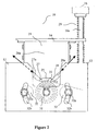
- FIG. 1 shows a perspective view of an example coating device according to the invention, using the gravity as a means of applying the fluid to the substrate.
- the device 10 comprises a coating tank 21 delimited, in its upper part, by four flanks 26a, 26b, 26c, 26d. These flanks can advantageously be made of polytetrafluoroethylene, taking into account the chemical resistance, thermal stability and the low coefficient of friction of it.
- the tray 21 comprises an opening 22 formed by the flanges 27,28 of two other flanks 27a, 28a, which will be described with reference to Figures 2 and 3.
- the coating device 10 further comprises a coating roller 31 next to the opening 22, beneath it, and whose width is generally between 20 and 60 cm.
- the width of the roll is not, however, theoretically limited; it is in practice in view of the risks of mechanical deformation of the roll (buckling).
- the diameter of the roll is preferably less than 100 mm and more great preference between 30 and 50 mm.
- an adhesive can be introduced into the coating tank 21 and a substrate strip 40 can be inserted between the roller 31 and the lower opening 22, through a space provided for this purpose and, if necessary , adapted to the thickness of the band (relief included).
- the space between the roller 31 and the lower opening 22 is typically between 0.1 and 7 mm, depending on the desired coating weight. For example, providing a space of about 5 mm, corresponding to a thickness of a substrate with its relief, provides a basis weight of between 50 and 5000 g / m 2 , depending on the resistance to crushing of the relief.
- the face to be coated of the substrate 40 is placed on the side of the opening 22. Under the action of gravity, the adhesive is applied to all or part of the strip, the opening having dimensions less than or equal to those of the roll.
- Such a device is particularly well adapted to the implementation of a process for coating a substrate with a fluid according to the invention.
- a fluid can, for for example, be a flow threshold fluid, preferably without solvent.
- the method according to the invention comprises steps of providing a substrate and a fluid; applying the fluid to the substrate; and of shearing of the fluid by the moving substrate relative to the fluid.
- the method according to the invention therefore proposes to apply the fluid on a substrate and exert a stress of shear on this fluid.
- the constraint of shear is enough to overcome the threshold flow of this fluid, it can flow and properly wet the substrate.
- the constraint of shear becomes below the flow threshold (for example, when the stress ceases), the fluid does not no longer flows.
- the coating process according to the invention may furthermore include a step of extending the substrate 40 (i.e. an opening of the relief or meshes 42 of the substrate, where appropriate) at least partially concomitant with the shearing stage of the fluid, in order to improve the shearing of the fluid by the substrate as well as the penetration of the fluid into the substrate.
- a step of extending the substrate 40 i.e. an opening of the relief or meshes 42 of the substrate, where appropriate
- the device and the method according to the invention are well suited for use with a threshold fluid flow such as a fluid whose viscosity, measured at using a Brookfield standard viscometer at 23 ° C, is between 100 and 200000 mPas, preferably between 200 and 4000 mPas, with a flow threshold of between 1 and 5000 Pa, preferably between 10 and 500 Pa and a delay to obtain the adjusted flow threshold between 1 and 20 seconds, and preferably between 2 and 10 seconds.
- a threshold fluid flow such as a fluid whose viscosity, measured at using a Brookfield standard viscometer at 23 ° C, is between 100 and 200000 mPas, preferably between 200 and 4000 mPas, with a flow threshold of between 1 and 5000 Pa, preferably between 10 and 500 Pa and a delay to obtain the adjusted flow threshold between 1 and 20 seconds, and preferably between 2 and 10 seconds.
- a threshold fluid flow such as a fluid whose viscosity, measured at using a Brookfield standard vis
- the fluid can both have a threshold of flow and Newtonian behavior once the threshold crossed, and stay perfectly suited for use with the device according to the invention.
- the device according to the invention is also compatible with a wide range of fluids without threshold flow, that is to say having a threshold of less than 1 Pa, but having an appropriate viscosity between 100 and 200000 mPas.
- the device and the method are particularly well suited for the application of a two-component polyurethane (PU2K) reactive adhesive, comprising a resin part comprising at least one polyol and a polyamine, and a hardener portion comprising at least minus one isocyanate.
- PU2K polyurethane
- Such a reactive mixture is susceptible to present a threshold of flow. It can furthermore advantageously be used without solvent, that is to say having a solvent content of less than 1% and, preferably less than 500 ppm by weight, in the device according to the invention.
- the drive of the substrate strip 40 around the roll 31 leads to shearing of the fluid by the substrate.
- Sufficient shear of an adhesive having a profile as described above increases the fluidity of this adhesive at the level of the lower opening, resulting in then a correct wetting of the fibers of the substrate.
- the passage of the strip on the roller 31 may furthermore lead to an extension of the substrate 40 (i.e. opening of the relief or meshes 42 of the substrate, the case appropriate), coating face side.
- an extension of the substrate 40 i.e. opening of the relief or meshes 42 of the substrate, the case appropriate
- This extension varies in particular depending on the diameter of the roll 31 as well as angles formed by the substrate of roll 31: we will talk about angles of arrival and exhaust depending on whether one is downstream or upstream of the roller 31, respectively.
- This extension is at least partially concomitant with the shearing of the adhesive, which improves the wetting of fibers of the substrate by the adhesive.
- the diameter of roll 31 of coating searched is as small as possible, in order to allow a maximum extension of the substrate 40, provided that diameter does not induce significant buckling of the roll.
- a roll diameter of between 30 and 50 mm allows optimize the extension of the substrate 40.
- a diameter of 40 mm is particularly suitable for the extension of substrates of various types. The extension of substrate 40 is resorbed just after the passage on the roll of coating 31 while the adhesive takes again the cohesion after shearing.
- the use of such device 10 with an adhesive having both a threshold flow and a rapid increase in cohesion improves the penetration of the fluid into the substrate without the to cross.
- the speed of drive of the band can in in addition to being adjusted (1 to 200 m / min, preferably 10 to 50 m / min) together with the physicochemical properties adhesive to allow precise weight control deposited adhesive, for example between 10 and 500 g / m2, according to the relief of the support.
- Such an adjustment makes it possible besides obtaining varied properties, depending on the application considered, such as fixing weaving, shaving loops of the substrate, the longitudinal cut or transverse to the paper cutter, welding ultrasound and fixation or stiffening of selvedges.
- the coating device according to the invention is furthermore particularly well suited for textile coating Velcro.
- the use of a roll coating 31 gives better coating results that a conventional device using a lip nozzle.
- we obtain through the invention a coating more tense and brighter.
- the device 10 according to the invention does not give rise to stops of production, even when used with adhesives having a rapid cohesion build-up.
- Figure 2 shows a side view of a device of coating 10 according to the invention.
- This view shows the flanges 27,28 flanks 27a, 28a, defining the opening 22 bottom of the tray 21, under which the roller is located 31.
- Flanks 27a, 28a may be inclined, so that the tray 21 has a funnel section, with an angle hopper adapted to facilitate the flow of fluid.
- another type of section for example rectangular, could also be suitable.
- coating device 10 in which the section of the ledges 27,28 is rounded tip-shaped at its end (the osculating circle at the end of a ledge a diameter typically between 0.5 and 15 mm), so to encourage the slipping of the band and to avoid any hitch with it when driven on the 31.
- the profile of the flanges 27, 28 of the example of device shown in Figure 2 results from a compromise between their machinability (the edges are in this example made of a metallic material) and the angle exhaust ⁇ sought.
- the angle corresponding to the tip, in section is typically between 20 ° and 40 °.
- recall means 29 can be provided. coating tank 21 against the coating roll 31 via the edges 27,28 or against the band, when this one is inserted. However, where it is desirable to space between the tray 21 and the coating roll 31, these means 29 are adapted to recall the tray 21 to an operating position. This position of operation leaves a free space between the tray 21 and the 31.
- the return means 29 comprise one or more coil springs. In this case, springs can to be in contact with the surfaces of the support 12, of a flat 14 and a sleeve 16. This sleeve can optionally be adjustable, that is to say it can be screwed on a rod 16a to adjust the return force of the spring.
- Mounting previous one also allows to adjust the position of operation of the tray 21 (including the height of the tray, the angles of pitch and roll), to dampen the vibrations of the system (for example when passing butt joints of the substrate band) and release constraints casualties engendered by the movement of the band of substrate 40.
- rollers 32 for guiding the substrate strip 40, as in the device example 10 shown on the Figure 2.
- the substrate can be inserted underneath or above a guide roller, depending on the angle of arrival and / or sought exhaust. These angles are those formed between the upper surface of the substrate and the surface bottom of a rim 27, 28.
- the wetting angles of the fluids used typically vary between 15 and 40 °.
- the figure also shows positioning means 32a, 32b of the guide roller. In this example, these means comprise a nut 32a screwed onto the shaft of a roller 32 guide and tightening a washer resting on a bean 32b. The nut 32a thus makes it possible to adjust the position of the guide roller shaft 32 located on one side of the roller 31.
- Similar positioning means may be provided on the opposite side of the roll coating 31 to allow adjustment of the position another guide roll 32.
- a roller 32 can for example be provided with rollers 34, whose spacing is possibly adjustable to the width of the substrate, in order to guide the substrate strip 40 through the device coating 10.
- means of positioning 32a, 32b along an eccentric axis with respect to the roller shaft 32 like the example shown on Figure 2.
- means of offset positioning can cover a more wide angle of arrival and / or departure substrate on the coating roll 31.
- these means allow to adjust the angle of arrival and / or exhaust of the substrate, and more precisely with a mechanism not eccentric.
- These angles will preferably be adjusted to a value greater than that of the wetting angle of fluid used, in order to avoid the accumulation of fluid and, thus, to decrease the frequency of the stops of production.
- the position of a roll 32 may, where appropriate, be adjusted in particular in height to stretch the band of substrate 40 (the substrate then being inserted under the roll 32) and while guiding it so, for example, to optimize the extension of the substrate 40 during its passage at the level of the opening 22.
- Figure 3 shows a schematic view from above of a part of a coating device 10, not to scale. More particularly, the figure shows flanks 27a, 28a of the coating tank 21, whose edges 27,28 define the opening 22.
- the length of the opening i.e. according to the direction of circulation of the substrate
- Drawers 23,24 are inserted in the opening thus defined, in which they can slide.
- Other flanks 26a, 26c of the ferry 21 are shown in the figure.
- the drawers end by gripping means 23a, 24a adapted for a drawer handling from outside the device 10.
- These gripping means 23a, 24a can include means of attachment, such as pressure or micrometric adjustment screws, for secure the positioning of the drawers 23,24.
- the parts drawers are represented by dotted lines: the length of these parts can be adapted according to the desired degree of closure of the opening 22 by the drawers 23,24. In particular, it is possible to provide a length of drawers so that it allows a total filling of the opening 22. It is thus possible to obtain a removable tray, this which facilitates the exploitation, the change of substrate and cleaning. It should be noted that the same result can be obtained using a single drawer.
- the figure shows also a substrate strip 40 inserted into the device 10, that is to say under the tray 21 and above the roller 31 (not shown). The pattern symbolizes the side of the face to be coated with the substrate.
- a fluid 60 fills partially the tray 21, its contours being delimited by dots. For the sake of clarity, we have chosen to represent a translucent fluid 60.
- the position of contour of the fluid at the flanks 27a, 28a is explained in that these flanks 27a, 28a are inclined, in the embodiment shown in the figure.
- the presence fluid 60 in the tray 21 partly obscures the pattern of substrate 40 visible under the opening 22.
- drawers 23,24 allows control the width of the surface to be coated. After his under the opening 22, the substrate 40 is partially coated on a surface corresponding to the width delimited by the drawers 23,24. The coated surface substrate is symbolized an altered pattern with respect to the pattern of the substrate 40 before coating.
- a tray 21 is obtained. " variable geometry ". It is also possible to do vary the geometry of the tank 21 together with physicochemical properties of the adhesive, in order to obtaining specific properties of the band of substrate 40.
- the device 10 described above can also be likely to work in both directions of circulation of the substrate. This is the case of the device or device parts shown in FIGS. 1 to 4. For this, we can impose a certain symmetry of device with respect to the coating roll, in particular regards the section and orientation of the flanges 27, 28 (as shown in FIGS. 2 and 4) and the rollers guide (see in particular Figures 2 and 3).
- This option allows for example to circulate the band of substrate through the device 10 while adjusting the device settings (such as angles inlet / exhaust and the height of the tank), then circulate the tape in the opposite direction, once settings completed. It saves several meters of substrate band, which turns out to be all the more advantageous that the substrate is expensive.
- the substrate strip can to be directed in an oven.
- the length of the oven is between 1 and 20 meters, its temperature varies between 50 and 250 ° C and the relative humidity is between 0 and 80%.
- the passage of substrate can also be multiplied inside the oven, in order to save money oven length.
- the speed of the substrate strip 40 can reach 60 meters per minute inside the oven.
- the adhesive may, according to its composition, regain fluidity (at least temporarily) and thus perfect the mooring.
- the parameters mentioned above can be adjusted from so that a mechanical grip takes place without that the adhesive does not cross the support. At the same time, cohesion of the adhesive can quickly increase under the effect of temperature, which favors conversion chemical.
- the chemical conversion rate obtained with a two-component polyurethane adhesive as described above can reach more than 98% out of oven. It is then sufficient to allow a winding of the substrate strip 40 without release paper (from English "release paper") and without stamping effects (" blocking ”) of the band ..
- the device 10 can still advantageously include a coil winding of the substrate.
- a winding roller can be located downstream of the coating roll 31 and, where appropriate, downstream of one or more rollers 32 and downstream of an oven. Rotating the winding roller may be enough on its own to set the band in motion along its conveying path. This does not exclude as much to resort to independent means of training for each of the rollers 31,32 involved in the device 10, in particular where it is desirable to exercise tension on the band.
- the invention significantly improves the coating substrates and can be implemented with substrates with a wide variety of texture.
- substrates that may be suitable, mention may be made of example substrates with wire brushes, papers nonstick, plastic films, especially polyester, polyamide, polypropylene and polyethylene, the metallic films or plastic films comprising metallized yarns, glass fabrics, films with a wood veneer, natural fiber fabrics (eg cotton fibers), antistatic fabrics, artificial textiles made from cellulose (eg rayon) and synthetic or natural nonwovens.
- Figure 4 schematically illustrates a view partial profile of a substrate 40 inserted into a coating device according to the invention.
- the substrate 40 inserted between the coating roller 31 and the flanges 27, 28 of the coating tray has a texture 42 (or relief) of any origin (for example due to weaving or fibers) symbolized by crenellations.
- the substrate 40 is stretched downstream and / or upstream of the device and the edges come flush the substrate.
- the mechanical stress exerted particularly by the roller 31 on the substrate leads to a spacing patterns or, again, at an opening of the relief forming the texture of the substrate. This gap or opening can not only improve fluid shear applied to the substrate but also allows the fluid to better penetrate the texture, that is to say better wet the substrate.
- the height of fluid above the substrate can be regulated, particularly at the level of the coating tank, this fluid height creating favorable hydrostatic pressure at anchor and impregnation, which it is not possible to get with a squeegee.
- a possible variant includes the use of a plurality of trays 21 and rollers 31 for coating for the successive coating of a substrate strip 40 by different fluids.
- Another variant concerns coating transfer, that is to say a method whereby a coating layer is applied on a temporary support (eg nonstick paper), which can be then possibly add a product of attachment, to finally allow the transfer of the coating layer, for example by means of a roller, on a final support such sheet metal or any other medium unsuitable for direct coating.
- a temporary support eg nonstick paper
Landscapes
- Application Of Or Painting With Fluid Materials (AREA)
- Coating Apparatus (AREA)
Applications Claiming Priority (2)
| Application Number | Priority Date | Filing Date | Title |
|---|---|---|---|
| FR0307969A FR2856941B1 (fr) | 2003-07-01 | 2003-07-01 | Dispositif et procede d'enduction |
| FR0307969 | 2003-07-01 |
Publications (2)
| Publication Number | Publication Date |
|---|---|
| EP1493496A1 true EP1493496A1 (de) | 2005-01-05 |
| EP1493496B1 EP1493496B1 (de) | 2008-04-09 |
Family
ID=33427660
Family Applications (1)
| Application Number | Title | Priority Date | Filing Date |
|---|---|---|---|
| EP04291649A Expired - Lifetime EP1493496B1 (de) | 2003-07-01 | 2004-06-30 | Beschichtungsvorrichtung und Verfahren |
Country Status (6)
| Country | Link |
|---|---|
| US (1) | US7749571B2 (de) |
| EP (1) | EP1493496B1 (de) |
| AT (1) | ATE391561T1 (de) |
| DE (1) | DE602004012927T2 (de) |
| ES (1) | ES2304589T3 (de) |
| FR (1) | FR2856941B1 (de) |
Families Citing this family (5)
| Publication number | Priority date | Publication date | Assignee | Title |
|---|---|---|---|---|
| DE102005019686B3 (de) * | 2005-04-22 | 2006-04-13 | Schmid Technology Systems Gmbh | Einrichtung und Verfahren zum Aufbringen einer gleichmäßigen, dünnen Flüssigkeitsschicht auf Substrate |
| EP2770965B1 (de) * | 2011-10-24 | 2021-12-01 | Bostik, Inc. | Neuartiges verfahren zur herstellung eines absorbierenden artikels |
| JP6851042B2 (ja) * | 2016-11-24 | 2021-03-31 | 積水化学工業株式会社 | 樹脂液塗布機 |
| US20190351447A1 (en) * | 2017-11-22 | 2019-11-21 | Acupac Packaging, Inc. | Method and apparatus for coating a substrate |
| CN113617598A (zh) * | 2021-07-21 | 2021-11-09 | 东风延锋汽车饰件系统有限公司 | 汽车内饰包覆表皮涂覆胶水装置及其涂覆方法 |
Citations (5)
| Publication number | Priority date | Publication date | Assignee | Title |
|---|---|---|---|---|
| US2620767A (en) * | 1951-09-20 | 1952-12-09 | Robert M Lehman | Filler machine |
| US3486482A (en) * | 1966-12-30 | 1969-12-30 | Westvaco Corp | Apparatus for coating traveling webs |
| US4554886A (en) * | 1984-02-27 | 1985-11-26 | Carter Carlos R | Apparatus for coating and cutting sheet material |
| JPH1147655A (ja) * | 1997-08-05 | 1999-02-23 | Fujikura Rubber Ltd | ナイフ塗布装置 |
| US6565660B1 (en) * | 1998-07-09 | 2003-05-20 | Reinhard Düspohl Maschinenbau Gmbh | Adhesive applicator device |
Family Cites Families (5)
| Publication number | Priority date | Publication date | Assignee | Title |
|---|---|---|---|---|
| US3936549A (en) * | 1972-11-17 | 1976-02-03 | The Kohler Coating Machinery Corporation | Method and apparatus for applying a liquid coating to strip material |
| US3891785A (en) * | 1973-03-20 | 1975-06-24 | Usm Corp | Process for forming a flexible polyurethane coating |
| US5876792A (en) * | 1988-03-14 | 1999-03-02 | Nextec Applications, Inc. | Methods and apparatus for controlled placement of a polymer composition into a web |
| JP3758098B2 (ja) * | 1995-10-16 | 2006-03-22 | 富士写真フイルム株式会社 | 塗布方法および塗布装置 |
| US6566560B2 (en) * | 1999-03-22 | 2003-05-20 | Immugen Pharmaceuticals, Inc. | Resorcinolic compounds |
-
2003
- 2003-07-01 FR FR0307969A patent/FR2856941B1/fr not_active Expired - Fee Related
-
2004
- 2004-06-30 EP EP04291649A patent/EP1493496B1/de not_active Expired - Lifetime
- 2004-06-30 ES ES04291649T patent/ES2304589T3/es not_active Expired - Lifetime
- 2004-06-30 DE DE602004012927T patent/DE602004012927T2/de not_active Expired - Lifetime
- 2004-06-30 AT AT04291649T patent/ATE391561T1/de active
- 2004-07-01 US US10/882,102 patent/US7749571B2/en not_active Expired - Fee Related
Patent Citations (5)
| Publication number | Priority date | Publication date | Assignee | Title |
|---|---|---|---|---|
| US2620767A (en) * | 1951-09-20 | 1952-12-09 | Robert M Lehman | Filler machine |
| US3486482A (en) * | 1966-12-30 | 1969-12-30 | Westvaco Corp | Apparatus for coating traveling webs |
| US4554886A (en) * | 1984-02-27 | 1985-11-26 | Carter Carlos R | Apparatus for coating and cutting sheet material |
| JPH1147655A (ja) * | 1997-08-05 | 1999-02-23 | Fujikura Rubber Ltd | ナイフ塗布装置 |
| US6565660B1 (en) * | 1998-07-09 | 2003-05-20 | Reinhard Düspohl Maschinenbau Gmbh | Adhesive applicator device |
Non-Patent Citations (1)
| Title |
|---|
| PATENT ABSTRACTS OF JAPAN vol. 1999, no. 05 31 May 1999 (1999-05-31) * |
Also Published As
| Publication number | Publication date |
|---|---|
| EP1493496B1 (de) | 2008-04-09 |
| FR2856941B1 (fr) | 2006-08-11 |
| DE602004012927T2 (de) | 2009-06-04 |
| ES2304589T3 (es) | 2008-10-16 |
| ATE391561T1 (de) | 2008-04-15 |
| US20050037142A1 (en) | 2005-02-17 |
| US7749571B2 (en) | 2010-07-06 |
| FR2856941A1 (fr) | 2005-01-07 |
| DE602004012927D1 (de) | 2008-05-21 |
Similar Documents
| Publication | Publication Date | Title |
|---|---|---|
| EP0115286B1 (de) | Verfahren zur Herstellung von Wegwerfwindeln und so hergestellte Wegwerfwindeln | |
| CA2352136C (fr) | Procede et dispositif de revetement en continu d'au moins une bande metallique par un film fluide en polymere reticulable | |
| FR2534494A1 (fr) | Procede et equipement pour appliquer un revetement resistant a l'usure sur un materiau de support mince, en metal, en forme de bande, et bande ainsi obtenue | |
| EP4241990A2 (de) | Formvorrichtung zum formen einer haltevorrichtung | |
| FR2887234A1 (fr) | Stabilisation de bande sur un support d'avance et coupe | |
| EP0554345B1 (de) | Windelhose mit elastischen elementen sowie verfahren und vorrichtung zu ihrer kontinuierlichen herstellung | |
| EP0501909B1 (de) | Vorrichtung und Verfahren zum Beleimen einer Bahn | |
| EP1493496B1 (de) | Beschichtungsvorrichtung und Verfahren | |
| FR2526370A1 (fr) | Procede et dispositif d'encrage pour machine d'imprimerie | |
| FR2585591A1 (fr) | Procede et dispositif pour l'application en continu d'une enduction reguliere sur une nappe de materiau passant sur un cylindre de contre-partie, en particulier une nappe de papier ou de carton | |
| FR2595673A1 (fr) | Perfectionnements aux enrouleuses a compression | |
| EP3545122B1 (de) | Vorrichtung zum strecken einer bahn zwischen einer kardiervorrichtung und einem kreuzleger | |
| CH395013A (fr) | Machine pour fabrication d'une structure composite | |
| BE1015008A3 (fr) | Plaque de base a interstice pour une enduction uniforme d'envers de tapis. | |
| CH636555A5 (fr) | Procede de fabrication de feuilles de matiere plastique. | |
| EP0461055B1 (de) | Klebstoffauftrageinrichtung für durchlaufende Warenbahnen in einem Apparat zur Herstellung von Papiererzeugnissen | |
| BE1025246B1 (fr) | Méthode et dispositif pour le revêtement de feuilles individuelles | |
| EP3170650B1 (de) | Herstellungsverfahren eines verbundstoffbandes und entsprechende herstellungsanlage für die herstellung eines segels eines segelbootes | |
| EP1343595B1 (de) | Verfahren und vorrichtung zur indirekten auftragung einer dünnen schicht | |
| FR3072693A1 (fr) | Procede et machine a regulation d'alimentation pour l'aiguilletage circulaire d'une structure textile formee a partir d'une nappe fibreuse helicoidale | |
| EP1190621A1 (de) | Vorrichtung zum Aufbringen einer pulverförmigen Substanz auf Objekten, insbesondere zum Salzen von Käse | |
| EP4366955A1 (de) | Tragbare maschine zum befeuchten der klebstoffbeschichteten fläche einer wandverkleidungsleiste | |
| FR2991556A1 (fr) | Procede de fabrication d'une bande textile et bande textile obtenue selon ledit procede | |
| BE633650A (de) | ||
| BE592594A (de) |
Legal Events
| Date | Code | Title | Description |
|---|---|---|---|
| PUAI | Public reference made under article 153(3) epc to a published international application that has entered the european phase |
Free format text: ORIGINAL CODE: 0009012 |
|
| AK | Designated contracting states |
Kind code of ref document: A1 Designated state(s): AT BE BG CH CY CZ DE DK EE ES FI FR GB GR HU IE IT LI LU MC NL PL PT RO SE SI SK TR |
|
| AX | Request for extension of the european patent |
Extension state: AL HR LT LV MK |
|
| 17P | Request for examination filed |
Effective date: 20050705 |
|
| RAP1 | Party data changed (applicant data changed or rights of an application transferred) |
Owner name: BOSTIK SA |
|
| AKX | Designation fees paid |
Designated state(s): AT BE BG CH CY CZ DE DK EE ES FI FR GB GR HU IE IT LI LU MC NL PL PT RO SE SI SK TR |
|
| 17Q | First examination report despatched |
Effective date: 20061213 |
|
| GRAP | Despatch of communication of intention to grant a patent |
Free format text: ORIGINAL CODE: EPIDOSNIGR1 |
|
| GRAS | Grant fee paid |
Free format text: ORIGINAL CODE: EPIDOSNIGR3 |
|
| GRAA | (expected) grant |
Free format text: ORIGINAL CODE: 0009210 |
|
| AK | Designated contracting states |
Kind code of ref document: B1 Designated state(s): AT BE BG CH CY CZ DE DK EE ES FI FR GB GR HU IE IT LI LU MC NL PL PT RO SE SI SK TR |
|
| REG | Reference to a national code |
Ref country code: GB Ref legal event code: FG4D Free format text: NOT ENGLISH |
|
| REG | Reference to a national code |
Ref country code: CH Ref legal event code: EP |
|
| REG | Reference to a national code |
Ref country code: IE Ref legal event code: FG4D Free format text: LANGUAGE OF EP DOCUMENT: FRENCH |
|
| REF | Corresponds to: |
Ref document number: 602004012927 Country of ref document: DE Date of ref document: 20080521 Kind code of ref document: P |
|
| REG | Reference to a national code |
Ref country code: CH Ref legal event code: NV Representative=s name: ZIMMERLI, WAGNER & PARTNER AG |
|
| PG25 | Lapsed in a contracting state [announced via postgrant information from national office to epo] |
Ref country code: SI Free format text: LAPSE BECAUSE OF FAILURE TO SUBMIT A TRANSLATION OF THE DESCRIPTION OR TO PAY THE FEE WITHIN THE PRESCRIBED TIME-LIMIT Effective date: 20080409 |
|
| REG | Reference to a national code |
Ref country code: ES Ref legal event code: FG2A Ref document number: 2304589 Country of ref document: ES Kind code of ref document: T3 |
|
| PG25 | Lapsed in a contracting state [announced via postgrant information from national office to epo] |
Ref country code: FI Free format text: LAPSE BECAUSE OF FAILURE TO SUBMIT A TRANSLATION OF THE DESCRIPTION OR TO PAY THE FEE WITHIN THE PRESCRIBED TIME-LIMIT Effective date: 20080409 Ref country code: BG Free format text: LAPSE BECAUSE OF FAILURE TO SUBMIT A TRANSLATION OF THE DESCRIPTION OR TO PAY THE FEE WITHIN THE PRESCRIBED TIME-LIMIT Effective date: 20080709 Ref country code: PT Free format text: LAPSE BECAUSE OF FAILURE TO SUBMIT A TRANSLATION OF THE DESCRIPTION OR TO PAY THE FEE WITHIN THE PRESCRIBED TIME-LIMIT Effective date: 20080909 |
|
| PG25 | Lapsed in a contracting state [announced via postgrant information from national office to epo] |
Ref country code: PL Free format text: LAPSE BECAUSE OF FAILURE TO SUBMIT A TRANSLATION OF THE DESCRIPTION OR TO PAY THE FEE WITHIN THE PRESCRIBED TIME-LIMIT Effective date: 20080409 |
|
| REG | Reference to a national code |
Ref country code: IE Ref legal event code: FD4D |
|
| PG25 | Lapsed in a contracting state [announced via postgrant information from national office to epo] |
Ref country code: CZ Free format text: LAPSE BECAUSE OF FAILURE TO SUBMIT A TRANSLATION OF THE DESCRIPTION OR TO PAY THE FEE WITHIN THE PRESCRIBED TIME-LIMIT Effective date: 20080409 Ref country code: SE Free format text: LAPSE BECAUSE OF FAILURE TO SUBMIT A TRANSLATION OF THE DESCRIPTION OR TO PAY THE FEE WITHIN THE PRESCRIBED TIME-LIMIT Effective date: 20080709 Ref country code: DK Free format text: LAPSE BECAUSE OF FAILURE TO SUBMIT A TRANSLATION OF THE DESCRIPTION OR TO PAY THE FEE WITHIN THE PRESCRIBED TIME-LIMIT Effective date: 20080409 Ref country code: MC Free format text: LAPSE BECAUSE OF NON-PAYMENT OF DUE FEES Effective date: 20080630 Ref country code: IE Free format text: LAPSE BECAUSE OF FAILURE TO SUBMIT A TRANSLATION OF THE DESCRIPTION OR TO PAY THE FEE WITHIN THE PRESCRIBED TIME-LIMIT Effective date: 20080409 |
|
| PLBE | No opposition filed within time limit |
Free format text: ORIGINAL CODE: 0009261 |
|
| STAA | Information on the status of an ep patent application or granted ep patent |
Free format text: STATUS: NO OPPOSITION FILED WITHIN TIME LIMIT |
|
| PG25 | Lapsed in a contracting state [announced via postgrant information from national office to epo] |
Ref country code: RO Free format text: LAPSE BECAUSE OF FAILURE TO SUBMIT A TRANSLATION OF THE DESCRIPTION OR TO PAY THE FEE WITHIN THE PRESCRIBED TIME-LIMIT Effective date: 20080409 Ref country code: SK Free format text: LAPSE BECAUSE OF FAILURE TO SUBMIT A TRANSLATION OF THE DESCRIPTION OR TO PAY THE FEE WITHIN THE PRESCRIBED TIME-LIMIT Effective date: 20080409 |
|
| 26N | No opposition filed |
Effective date: 20090112 |
|
| PG25 | Lapsed in a contracting state [announced via postgrant information from national office to epo] |
Ref country code: EE Free format text: LAPSE BECAUSE OF FAILURE TO SUBMIT A TRANSLATION OF THE DESCRIPTION OR TO PAY THE FEE WITHIN THE PRESCRIBED TIME-LIMIT Effective date: 20080409 |
|
| PG25 | Lapsed in a contracting state [announced via postgrant information from national office to epo] |
Ref country code: CY Free format text: LAPSE BECAUSE OF FAILURE TO SUBMIT A TRANSLATION OF THE DESCRIPTION OR TO PAY THE FEE WITHIN THE PRESCRIBED TIME-LIMIT Effective date: 20080409 |
|
| REG | Reference to a national code |
Ref country code: CH Ref legal event code: PFA Owner name: BOSTIK SA Free format text: BOSTIK SA#12, PLACE DE L'IRIS#92400 COURBEVOIE (FR) -TRANSFER TO- BOSTIK SA#12, PLACE DE L'IRIS#92400 COURBEVOIE (FR) |
|
| PG25 | Lapsed in a contracting state [announced via postgrant information from national office to epo] |
Ref country code: LU Free format text: LAPSE BECAUSE OF NON-PAYMENT OF DUE FEES Effective date: 20080630 Ref country code: HU Free format text: LAPSE BECAUSE OF FAILURE TO SUBMIT A TRANSLATION OF THE DESCRIPTION OR TO PAY THE FEE WITHIN THE PRESCRIBED TIME-LIMIT Effective date: 20081010 |
|
| PG25 | Lapsed in a contracting state [announced via postgrant information from national office to epo] |
Ref country code: GR Free format text: LAPSE BECAUSE OF FAILURE TO SUBMIT A TRANSLATION OF THE DESCRIPTION OR TO PAY THE FEE WITHIN THE PRESCRIBED TIME-LIMIT Effective date: 20080710 |
|
| PGFP | Annual fee paid to national office [announced via postgrant information from national office to epo] |
Ref country code: NL Payment date: 20120614 Year of fee payment: 9 Ref country code: TR Payment date: 20120521 Year of fee payment: 9 Ref country code: CH Payment date: 20120612 Year of fee payment: 9 |
|
| PGFP | Annual fee paid to national office [announced via postgrant information from national office to epo] |
Ref country code: GB Payment date: 20120627 Year of fee payment: 9 |
|
| PGFP | Annual fee paid to national office [announced via postgrant information from national office to epo] |
Ref country code: BE Payment date: 20120620 Year of fee payment: 9 |
|
| PGFP | Annual fee paid to national office [announced via postgrant information from national office to epo] |
Ref country code: ES Payment date: 20120726 Year of fee payment: 9 |
|
| PGFP | Annual fee paid to national office [announced via postgrant information from national office to epo] |
Ref country code: AT Payment date: 20120529 Year of fee payment: 9 |
|
| BERE | Be: lapsed |
Owner name: BOSTIK SA Effective date: 20130630 |
|
| REG | Reference to a national code |
Ref country code: NL Ref legal event code: V1 Effective date: 20140101 |
|
| REG | Reference to a national code |
Ref country code: CH Ref legal event code: PL |
|
| REG | Reference to a national code |
Ref country code: AT Ref legal event code: MM01 Ref document number: 391561 Country of ref document: AT Kind code of ref document: T Effective date: 20130630 |
|
| GBPC | Gb: european patent ceased through non-payment of renewal fee |
Effective date: 20130630 |
|
| PG25 | Lapsed in a contracting state [announced via postgrant information from national office to epo] |
Ref country code: BE Free format text: LAPSE BECAUSE OF NON-PAYMENT OF DUE FEES Effective date: 20130630 |
|
| PG25 | Lapsed in a contracting state [announced via postgrant information from national office to epo] |
Ref country code: NL Free format text: LAPSE BECAUSE OF NON-PAYMENT OF DUE FEES Effective date: 20140101 Ref country code: LI Free format text: LAPSE BECAUSE OF NON-PAYMENT OF DUE FEES Effective date: 20130630 Ref country code: GB Free format text: LAPSE BECAUSE OF NON-PAYMENT OF DUE FEES Effective date: 20130630 Ref country code: CH Free format text: LAPSE BECAUSE OF NON-PAYMENT OF DUE FEES Effective date: 20130630 |
|
| PG25 | Lapsed in a contracting state [announced via postgrant information from national office to epo] |
Ref country code: AT Free format text: LAPSE BECAUSE OF NON-PAYMENT OF DUE FEES Effective date: 20130630 |
|
| REG | Reference to a national code |
Ref country code: ES Ref legal event code: FD2A Effective date: 20140707 |
|
| PG25 | Lapsed in a contracting state [announced via postgrant information from national office to epo] |
Ref country code: ES Free format text: LAPSE BECAUSE OF NON-PAYMENT OF DUE FEES Effective date: 20130701 |
|
| REG | Reference to a national code |
Ref country code: FR Ref legal event code: PLFP Year of fee payment: 13 |
|
| REG | Reference to a national code |
Ref country code: FR Ref legal event code: PLFP Year of fee payment: 14 |
|
| PG25 | Lapsed in a contracting state [announced via postgrant information from national office to epo] |
Ref country code: TR Free format text: LAPSE BECAUSE OF NON-PAYMENT OF DUE FEES Effective date: 20130630 |
|
| REG | Reference to a national code |
Ref country code: FR Ref legal event code: PLFP Year of fee payment: 15 |
|
| PGFP | Annual fee paid to national office [announced via postgrant information from national office to epo] |
Ref country code: DE Payment date: 20180619 Year of fee payment: 15 |
|
| PGFP | Annual fee paid to national office [announced via postgrant information from national office to epo] |
Ref country code: FR Payment date: 20180514 Year of fee payment: 15 |
|
| PGFP | Annual fee paid to national office [announced via postgrant information from national office to epo] |
Ref country code: IT Payment date: 20180625 Year of fee payment: 15 |
|
| REG | Reference to a national code |
Ref country code: DE Ref legal event code: R119 Ref document number: 602004012927 Country of ref document: DE |
|
| PG25 | Lapsed in a contracting state [announced via postgrant information from national office to epo] |
Ref country code: DE Free format text: LAPSE BECAUSE OF NON-PAYMENT OF DUE FEES Effective date: 20200101 Ref country code: IT Free format text: LAPSE BECAUSE OF NON-PAYMENT OF DUE FEES Effective date: 20190630 |
|
| PG25 | Lapsed in a contracting state [announced via postgrant information from national office to epo] |
Ref country code: FR Free format text: LAPSE BECAUSE OF NON-PAYMENT OF DUE FEES Effective date: 20190630 |