EP1508546A1 - Antriebsvorrichtung für kreisförmige aufzugstür - Google Patents
Antriebsvorrichtung für kreisförmige aufzugstür Download PDFInfo
- Publication number
- EP1508546A1 EP1508546A1 EP02728187A EP02728187A EP1508546A1 EP 1508546 A1 EP1508546 A1 EP 1508546A1 EP 02728187 A EP02728187 A EP 02728187A EP 02728187 A EP02728187 A EP 02728187A EP 1508546 A1 EP1508546 A1 EP 1508546A1
- Authority
- EP
- European Patent Office
- Prior art keywords
- driving
- cylindrical elevator
- link
- cylindrical
- belt
- Prior art date
- Legal status (The legal status is an assumption and is not a legal conclusion. Google has not performed a legal analysis and makes no representation as to the accuracy of the status listed.)
- Granted
Links
Images


Classifications
-
- B—PERFORMING OPERATIONS; TRANSPORTING
- B66—HOISTING; LIFTING; HAULING
- B66B—ELEVATORS; ESCALATORS OR MOVING WALKWAYS
- B66B13/00—Doors, gates, or other apparatus controlling access to, or exit from, cages or lift well landings
- B66B13/02—Door or gate operation
- B66B13/06—Door or gate operation of sliding doors
- B66B13/08—Door or gate operation of sliding doors guided for horizontal movement
-
- B—PERFORMING OPERATIONS; TRANSPORTING
- B66—HOISTING; LIFTING; HAULING
- B66B—ELEVATORS; ESCALATORS OR MOVING WALKWAYS
- B66B13/00—Doors, gates, or other apparatus controlling access to, or exit from, cages or lift well landings
- B66B13/02—Door or gate operation
-
- E—FIXED CONSTRUCTIONS
- E05—LOCKS; KEYS; WINDOW OR DOOR FITTINGS; SAFES
- E05F—DEVICES FOR MOVING WINGS INTO OPEN OR CLOSED POSITION; CHECKS FOR WINGS; WING FITTINGS NOT OTHERWISE PROVIDED FOR, CONCERNED WITH THE FUNCTIONING OF THE WING
- E05F15/00—Power-operated mechanisms for wings
- E05F15/60—Power-operated mechanisms for wings using electrical actuators
- E05F15/603—Power-operated mechanisms for wings using electrical actuators using rotary electromotors
- E05F15/632—Power-operated mechanisms for wings using electrical actuators using rotary electromotors for horizontally-sliding wings
- E05F15/643—Power-operated mechanisms for wings using electrical actuators using rotary electromotors for horizontally-sliding wings operated by flexible elongated pulling elements, e.g. belts, chains or cables
-
- E—FIXED CONSTRUCTIONS
- E05—LOCKS; KEYS; WINDOW OR DOOR FITTINGS; SAFES
- E05F—DEVICES FOR MOVING WINGS INTO OPEN OR CLOSED POSITION; CHECKS FOR WINGS; WING FITTINGS NOT OTHERWISE PROVIDED FOR, CONCERNED WITH THE FUNCTIONING OF THE WING
- E05F15/00—Power-operated mechanisms for wings
- E05F15/60—Power-operated mechanisms for wings using electrical actuators
- E05F15/603—Power-operated mechanisms for wings using electrical actuators using rotary electromotors
- E05F15/632—Power-operated mechanisms for wings using electrical actuators using rotary electromotors for horizontally-sliding wings
- E05F15/649—Power-operated mechanisms for wings using electrical actuators using rotary electromotors for horizontally-sliding wings operated by swinging arms
-
- E—FIXED CONSTRUCTIONS
- E05—LOCKS; KEYS; WINDOW OR DOOR FITTINGS; SAFES
- E05Y—INDEXING SCHEME ASSOCIATED WITH SUBCLASSES E05D AND E05F, RELATING TO CONSTRUCTION ELEMENTS, ELECTRIC CONTROL, POWER SUPPLY, POWER SIGNAL OR TRANSMISSION, USER INTERFACES, MOUNTING OR COUPLING, DETAILS, ACCESSORIES, AUXILIARY OPERATIONS NOT OTHERWISE PROVIDED FOR, APPLICATION THEREOF
- E05Y2201/00—Constructional elements; Accessories therefor
- E05Y2201/60—Suspension or transmission members; Accessories therefor
- E05Y2201/622—Suspension or transmission members elements
- E05Y2201/684—Rails; Tracks
-
- E—FIXED CONSTRUCTIONS
- E05—LOCKS; KEYS; WINDOW OR DOOR FITTINGS; SAFES
- E05Y—INDEXING SCHEME ASSOCIATED WITH SUBCLASSES E05D AND E05F, RELATING TO CONSTRUCTION ELEMENTS, ELECTRIC CONTROL, POWER SUPPLY, POWER SIGNAL OR TRANSMISSION, USER INTERFACES, MOUNTING OR COUPLING, DETAILS, ACCESSORIES, AUXILIARY OPERATIONS NOT OTHERWISE PROVIDED FOR, APPLICATION THEREOF
- E05Y2800/00—Details, accessories and auxiliary operations not otherwise provided for
- E05Y2800/26—Form or shape
- E05Y2800/266—Form or shape curved
-
- E—FIXED CONSTRUCTIONS
- E05—LOCKS; KEYS; WINDOW OR DOOR FITTINGS; SAFES
- E05Y—INDEXING SCHEME ASSOCIATED WITH SUBCLASSES E05D AND E05F, RELATING TO CONSTRUCTION ELEMENTS, ELECTRIC CONTROL, POWER SUPPLY, POWER SIGNAL OR TRANSMISSION, USER INTERFACES, MOUNTING OR COUPLING, DETAILS, ACCESSORIES, AUXILIARY OPERATIONS NOT OTHERWISE PROVIDED FOR, APPLICATION THEREOF
- E05Y2900/00—Application of doors, windows, wings or fittings thereof
- E05Y2900/10—Application of doors, windows, wings or fittings thereof for buildings or parts thereof
- E05Y2900/104—Application of doors, windows, wings or fittings thereof for buildings or parts thereof for elevators
Definitions
- the present invention relates to a cylindrical elevator door driving device.
- a panel of an elevator cage door is formed by a plane, and the cage door is opened and closed by straight movement in the right-and-left direction.
- cylindrical elevators having a cylindrical cage(s) have been used.
- the cage door is formed so as to be a part of the cylindrical cage to match the shape of the cage, and thus the cross-sectional shape of the cage door of a plane perpendicular to the elevating direction is arcuate. That is, the cylindrical elevator door that is opened and closed to the right and left along an arcuate path is used as a cage door.
- a cylindrical elevator is described in Japanese unexamined utility model laid-open No. 52-56862.
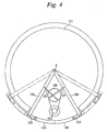
- FIG 4 is a schematic view showing one example of a basic construction of a door opening/closing driving device for a cylindrical elevator.
- the cylindrical elevator door is made up of a curved door panel, a door hanger for hanging an upper part of the door, a door rail, a sill for guiding a lower part of the door, and the like.
- the curved door panel is opened and closed by a driving device provided on the ceiling of the cage and a linkage that moves in association with the driving device.
- Curved door panels 102 are provided on the outside of a cylindrical cage 101 so as to be slidable along the outer peripheral surface of the cage 101 by means of a door rail.
- driving links 104 are provided symmetrically.
- the driving link 104 is a linkage for driving the curved door panel 102.
- One end of the driving link 104 is connected to a supporting point C, which is the rotation center of the curved door panel 102 and also the center of the cage 101, and the other end thereof is connected to an upper part of the curved door panel 102 via a small link 103.
- a door motor 105 and a speed reducing pulley 106 are arranged in a fan-shaped space formed by the two driving links 104.
- the door motor 105 and the speed reducing pulley 106 are fixed on the top of the cage 101, and an outer peripheral portion of the speed reducing pulley 106 and an intermediate portion of the driving link 104 are connected to each other by a connecting rod 107.
- the sizes of the door motor 105 and the speed reducing pulley 106 must be larger than the fixed sizes to obtain a predetermined driving force, and thus the miniaturization thereof has a limit.
- the conventional driving device it is difficult to arrange the elements in a region other than the fan-shaped space formed by the two driving links 104 because of a constructional restriction such that the rotation center of the driving link 104 is caused to coincide with the center of the cylindrical cage 101. Therefore, when the cage 101 is small, it is difficult to arrange the driving elements such as the door motor 105 and the speed reducing pulley 106.
- a planar space occupied by the elements for the driving device is about a half of a planar space occupied by the cage 101, as shown in Figure 4. Therefore, when the size of the cage 101 becomes large, the sizes of the elements such as the driving link 104, the door motor 105, the speed-reducing pulley 106, and the connecting rod 107 are made large, and thus the driving device itself becomes a large unit. Accordingly, there arises problems of increased unit weight and increased unit cost.
- an object of the present invention is to provide a cylindrical elevator door driving device which can be applied to various cage sizes, can be installed on a space-saving and small-size cage, and has high workability in assembly and installation.
- a cylindrical elevator door driving device which is provided on a cylindrical elevator, comprising a driving link for opening and closing a cylindrical elevator door by a predetermined rotating operation, a driving means for rotating the driving link, and a moving means for moving the rotation center of the driving link on a predetermined path. Since the rotation center of the driving link is moved, the rotation center need not be arranged at the center of the cylindrical elevator. For this reason, the driving device can be provided only in a limited portion of the planar region of a cage without being restricted by the cage size. Therefore, the driving device can be applied to various cage sizes, and the space for the driving device can be saved.
- the driving means for turning the driving link and the moving means for moving the rotation center may be a driving source, such as a motor, itself, or may include a link mechanism, belt mechanism, gear, and pulley for transmitting the operation of the driving source.
- the moving means may be a guide member for regulating the path of rotation center, and the rotation center may be moved by the operation of the driving means.
- the moving means has a guide member provided along the path on which the rotation center of the driving link moves the sliding member along the guide member.
- the guide member is provided at a position closer to said cylindrical elevator door than to the center of the cylindrical elevator. Since the guide member is provided at a position close to the cylindrical elevator door, the driving unit can be arranged in only a region near the cylindrical elevator door, so space saving can be attained, and also the driving unit can be applied to a small cage.
- the moving means moves the rotation centers of driving links corresponding to the two cylindrical elevator doors symmetrically in the direction that the cylindrical elevator doors move. Even in the case where two cylindrical elevator doors that open and close symmetrically in the right-and-left direction are provided, by moving the rotation center of the driving link symmetrically in the direction such that the cylindrical elevator doors move, the driving device can be applied to various cage sizes, and space saving can be attained.
- the driving means has a driving shaft connected to a driving source, a driven shaft, a belt which is set around the driving shaft and the driving shaft is moved along with the rotation of the driving shaft, and belt gripping members mounted at predetermined positions on the forward side and the backward side of the belt, the driving links corresponding to the two cylindrical elevator doors are connected to the belt gripping members on the forward side and the backward side of the belt, and the rotation centers of the driving links are moved symmetrically in the direction that the cylindrical elevator doors move by the movement of the belt.
- the rotation centers of the driving links can be moved symmetrically in the direction that the cylindrical elevator doors move by the movement of the belt.
- the improved cylindrical elevator door driving device of the aforementioned invention has a link member, of which one end is connected to the rotation center of the driving link corresponding to each of the two cylindrical elevator doors, a slider rail provided along the symmetrical axis of the movement paths of the two cylindrical elevator doors, and a slider which moves along the slider rail and to which the other end of the link member is connected.
- Figures 1, 2 and 3 are schematic views of a cylindrical elevator door driving device in accordance with an embodiment of the present invention.
- Figure 1 is a plan view showing a state in which curved door panels are fully closed
- Figure 3 is a plan view showing a state in which curved door panels are fully opened.
- Figure 2 is a side view of a driving device viewed from the outside of a cage 1 in the lengthwise direction of a slider rail 14 shown in Figure 1.
- curved door panels 2 are provided on the outside of the cylindrical cage 1.
- the curved door panel 2 is hung by a door hanger 9 that is hung from a door rail 8, and is provided so as to be slidable along the door rail 8.
- a door motor 5 On the cage center side of the curved door panel 2 there are provided a door motor 5, a driving pulley 10 installed on the output shaft of the door motor 5, and a driven pulley 11, and a belt 12 is set around the driving pulley 10 and the driven pulley 11.
- a guide 13 is provided along the belt 12, and rollers 17 that slide along the guide 13 are provided. Also, a slider rail 14 is provided along the symmetrical axis of the movement paths of the two curved door panels 2, and the slider rail 14 is inserted through a slider 15. Therefore, the slider 15 moves along the slider rail 15.
- the slider 15 is connected to the roller 17 via a link 16. Specifically, one end of the link 16 is pin-connected to the slider 15 so as to be turned with respect to the slider 15, and the other end thereof is pin-connected to the roller 17.
- roller 17 is connected to the door hanger 9 via a link 18.
- One end of the link 18 is pin-connected to the roller 17, and the other end thereof is pin-connected to the door hanger 9.
- the belt 12 is mounted with belt grippers 19 and 20. As shown in Figure 2, the belt gripper 19 is mounted on the upper side of the belt 12, and the belt gripper 20 is mounted on the lower side of the belt 12. Therefore, when the belt 12 is moved in a fixed direction, the belt gripper 19 and the belt gripper 20 move in the direction opposite to each other.
- the belt gripper 19, 20 includes a belt gripper body 19a, 20a fixed to the belt 12 and a link portion 19b, 20b. One end of the link portion 19b, 20b is pin-connected to the belt gripper body 19a, 20a, and the other end of the link portion 19b, 20b is pin-connected to a portion near the central portion of the link 18.
- the left and right belt gripper bodies 19a and 20a mounted on the belt 12 move in the direction indicated by arrow A.
- the link portions 19b and 20b, of which one end is pin-connected to the belt gripper bodies 19a and 20a are moved so as to be opened toward the outside of the cage 1, so that the left and right links 18 are moved in the direction such that the right and left links 18 are opened toward the outside of the cage 1.
- the link 18 turns around the rotation center B in the door opening direction while the roller 17, on which the rotation center B is located, is moved toward the outside of the cage 1 along the guide 13.
- the rotational force of the link 18 is transmitted to the door hanger 9, so that the door panel 2 is moved in the door opening direction while drawing an arc along the door rail 8 as shown in Figure 3.
- the whole of the driving device can be arranged only in a region near the curved door panel 2. Also, since the rotation center of the driving link 18 need not be arranged at the center of the cylindrical cage 1, the size, shape, arrangement, etc. of element of the driving device are not restricted by the size of the cage 1. Therefore, even if the size of the cage 1 is changed, a common driving device can be used, and hence the degree of freedom in designing a cylindrical elevator can be enhanced significantly.
- the driving device is arranged in a front portion on the entrance side on the ceiling of the cage 1, the space factor can be improved. That is, even if the elevator is small in size, the driving device can be arranged leaving some surplus of space.
- rotation centers B of the right and left driving links 4 are independent of each other, even in the case where the accuracies of the right and left driving devices are different from each other, assembly and installation can be accomplished easily by individually adjusting the position of the center B.
- the cylindrical elevator door driving device in accordance with the present invention can be applied to various cage sizes without design change, can be installed even on a space-saving and small-size cage, and has high workability in assembly and installation, so it is useful for various types of cylindrical elevators.
Landscapes
- Elevator Door Apparatuses (AREA)
Applications Claiming Priority (1)
| Application Number | Priority Date | Filing Date | Title |
|---|---|---|---|
| PCT/JP2002/005213 WO2003099697A1 (en) | 2002-05-29 | 2002-05-29 | Drive device for circular elevator door |
Publications (3)
| Publication Number | Publication Date |
|---|---|
| EP1508546A1 true EP1508546A1 (de) | 2005-02-23 |
| EP1508546A4 EP1508546A4 (de) | 2010-05-05 |
| EP1508546B1 EP1508546B1 (de) | 2012-05-09 |
Family
ID=29561094
Family Applications (1)
| Application Number | Title | Priority Date | Filing Date |
|---|---|---|---|
| EP02728187A Expired - Lifetime EP1508546B1 (de) | 2002-05-29 | 2002-05-29 | Antriebsvorrichtung für kreisförmige aufzugstür |
Country Status (5)
| Country | Link |
|---|---|
| EP (1) | EP1508546B1 (de) |
| JP (1) | JPWO2003099697A1 (de) |
| KR (1) | KR100576229B1 (de) |
| CN (1) | CN1292974C (de) |
| WO (1) | WO2003099697A1 (de) |
Cited By (1)
| Publication number | Priority date | Publication date | Assignee | Title |
|---|---|---|---|---|
| EP2177467A1 (de) | 2008-10-14 | 2010-04-21 | BC Lift A/S | Rotierende Hebevorrichtung |
Families Citing this family (7)
| Publication number | Priority date | Publication date | Assignee | Title |
|---|---|---|---|---|
| JP5395324B2 (ja) * | 2006-10-25 | 2014-01-22 | 株式会社日立製作所 | ドア開閉装置 |
| KR101356111B1 (ko) * | 2012-07-10 | 2014-01-28 | 정희섭 | 엘리베이터 장치 |
| CN103086239B (zh) * | 2012-11-19 | 2014-12-10 | 江南嘉捷电梯股份有限公司 | 轿厢折角开门结构 |
| CN109422182B (zh) * | 2017-08-31 | 2022-02-11 | 富士达株式会社 | 电梯的轿厢用门装置 |
| CN109132812A (zh) * | 2018-08-31 | 2019-01-04 | 周晓锋 | 一种圆弧形电梯门机 |
| CN111452804B (zh) * | 2020-04-30 | 2024-09-24 | 北京起重运输机械设计研究院有限公司 | 吊厢门控制机构及索道吊厢系统 |
| JP7569612B2 (ja) * | 2021-05-31 | 2024-10-18 | 株式会社イノアックコーポレーション | 把持装置 |
Family Cites Families (5)
| Publication number | Priority date | Publication date | Assignee | Title |
|---|---|---|---|---|
| JPS5516924Y2 (de) * | 1976-12-23 | 1980-04-19 | ||
| JPH027168Y2 (de) * | 1981-05-23 | 1990-02-21 | ||
| JPH0743107Y2 (ja) * | 1988-09-29 | 1995-10-04 | 株式会社東芝 | エレベータの円形ドア駆動装置 |
| DE19606209C2 (de) * | 1996-02-21 | 2001-08-09 | Hein Gmbh Christian | Antriebsvorrichtung für eine Aufzugstür |
| US6032762A (en) * | 1998-08-05 | 2000-03-07 | Vertisys International, Inc. | Door operator for elevators having curved doors |
-
2002
- 2002-05-29 KR KR1020047000638A patent/KR100576229B1/ko not_active Expired - Fee Related
- 2002-05-29 CN CNB028149351A patent/CN1292974C/zh not_active Expired - Fee Related
- 2002-05-29 JP JP2004507364A patent/JPWO2003099697A1/ja active Pending
- 2002-05-29 WO PCT/JP2002/005213 patent/WO2003099697A1/ja not_active Ceased
- 2002-05-29 EP EP02728187A patent/EP1508546B1/de not_active Expired - Lifetime
Cited By (1)
| Publication number | Priority date | Publication date | Assignee | Title |
|---|---|---|---|---|
| EP2177467A1 (de) | 2008-10-14 | 2010-04-21 | BC Lift A/S | Rotierende Hebevorrichtung |
Also Published As
| Publication number | Publication date |
|---|---|
| EP1508546A4 (de) | 2010-05-05 |
| CN1292974C (zh) | 2007-01-03 |
| WO2003099697A1 (en) | 2003-12-04 |
| KR100576229B1 (ko) | 2006-05-03 |
| EP1508546B1 (de) | 2012-05-09 |
| CN1535242A (zh) | 2004-10-06 |
| JPWO2003099697A1 (ja) | 2005-09-22 |
| KR20040015812A (ko) | 2004-02-19 |
Similar Documents
| Publication | Publication Date | Title |
|---|---|---|
| EP1508546B1 (de) | Antriebsvorrichtung für kreisförmige aufzugstür | |
| US20030089042A1 (en) | Coreless motor door closure system | |
| EP1331346B1 (de) | Automatische Öffnungs- und Schliessvorrichtung für ein Fahrzeug | |
| US5497674A (en) | Industrial robot | |
| US7855352B2 (en) | Shielding door device for radiation inspection system | |
| CN114061136A (zh) | 用于导风板的运动机构、空调器 | |
| CN101168425B (zh) | 电梯门开闭装置 | |
| JPH0281888A (ja) | エレベータ用中央両引き戸装置 | |
| US5715929A (en) | Charging device for semiconductor processing installations | |
| US9822575B2 (en) | Movable body driving device | |
| EP1631519B1 (de) | Teleskopische gekrümmte aufzugstüren | |
| JPH0743107Y2 (ja) | エレベータの円形ドア駆動装置 | |
| EP4063601B1 (de) | Drehschwenktür | |
| JPH11348771A (ja) | プラットフォームドア制御システム | |
| EP1276950B1 (de) | Antriebsvorrichtung zum automatischen betrieb eines schliesssystems für ein kraftfahrzeug | |
| EP1810780B1 (de) | Teilehandhabungsvorrichtung und technische handhabungsvorrichtung mit der vorrichtung | |
| CN216747773U (zh) | 一种样本分析急诊装置 | |
| CN216977142U (zh) | 用于导风板的运动组件、驱动盒 | |
| KR102739749B1 (ko) | 이송장치의 홀 마감 장치 | |
| CN110843956A (zh) | Agv装置 | |
| JP2549215B2 (ja) | エレベーターの戸開閉装置 | |
| JP2003285284A (ja) | スカラロボット | |
| KR200268628Y1 (ko) | 엘리베이터 도어 개폐장치 | |
| JP2003285282A (ja) | スカラロボット | |
| CZ20032402A3 (cs) | Zařízení pro přemístění přestavovaného prvku vůči rámu |
Legal Events
| Date | Code | Title | Description |
|---|---|---|---|
| PUAI | Public reference made under article 153(3) epc to a published international application that has entered the european phase |
Free format text: ORIGINAL CODE: 0009012 |
|
| 17P | Request for examination filed |
Effective date: 20040113 |
|
| AK | Designated contracting states |
Kind code of ref document: A1 Designated state(s): AT BE CH CY DE DK ES FI FR GB GR IE IT LI LU MC NL PT SE TR |
|
| AX | Request for extension of the european patent |
Extension state: AL LT LV MK RO SI |
|
| DAX | Request for extension of the european patent (deleted) | ||
| RBV | Designated contracting states (corrected) |
Designated state(s): DE |
|
| RAP1 | Party data changed (applicant data changed or rights of an application transferred) |
Owner name: MITSUBISHI DENKI KABUSHIKI KAISHA |
|
| A4 | Supplementary search report drawn up and despatched |
Effective date: 20100401 |
|
| 17Q | First examination report despatched |
Effective date: 20101004 |
|
| GRAP | Despatch of communication of intention to grant a patent |
Free format text: ORIGINAL CODE: EPIDOSNIGR1 |
|
| GRAS | Grant fee paid |
Free format text: ORIGINAL CODE: EPIDOSNIGR3 |
|
| GRAA | (expected) grant |
Free format text: ORIGINAL CODE: 0009210 |
|
| AK | Designated contracting states |
Kind code of ref document: B1 Designated state(s): DE |
|
| REG | Reference to a national code |
Ref country code: DE Ref legal event code: R096 Ref document number: 60242875 Country of ref document: DE Effective date: 20120705 |
|
| PLBE | No opposition filed within time limit |
Free format text: ORIGINAL CODE: 0009261 |
|
| STAA | Information on the status of an ep patent application or granted ep patent |
Free format text: STATUS: NO OPPOSITION FILED WITHIN TIME LIMIT |
|
| 26N | No opposition filed |
Effective date: 20130212 |
|
| REG | Reference to a national code |
Ref country code: DE Ref legal event code: R097 Ref document number: 60242875 Country of ref document: DE Effective date: 20130212 |
|
| REG | Reference to a national code |
Ref country code: DE Ref legal event code: R084 Ref document number: 60242875 Country of ref document: DE |
|
| REG | Reference to a national code |
Ref country code: DE Ref legal event code: R084 Ref document number: 60242875 Country of ref document: DE Effective date: 20141107 |
|
| PGFP | Annual fee paid to national office [announced via postgrant information from national office to epo] |
Ref country code: DE Payment date: 20150527 Year of fee payment: 14 |
|
| REG | Reference to a national code |
Ref country code: DE Ref legal event code: R119 Ref document number: 60242875 Country of ref document: DE |
|
| PG25 | Lapsed in a contracting state [announced via postgrant information from national office to epo] |
Ref country code: DE Free format text: LAPSE BECAUSE OF NON-PAYMENT OF DUE FEES Effective date: 20161201 |