EP1510599A2 - Herstellungsverfahren einer Matrize, Matrize und optische Aufzeichnungsträger - Google Patents
Herstellungsverfahren einer Matrize, Matrize und optische Aufzeichnungsträger Download PDFInfo
- Publication number
- EP1510599A2 EP1510599A2 EP04016511A EP04016511A EP1510599A2 EP 1510599 A2 EP1510599 A2 EP 1510599A2 EP 04016511 A EP04016511 A EP 04016511A EP 04016511 A EP04016511 A EP 04016511A EP 1510599 A2 EP1510599 A2 EP 1510599A2
- Authority
- EP
- European Patent Office
- Prior art keywords
- stamper
- father
- film
- father stamper
- surface treatment
- Prior art date
- Legal status (The legal status is an assumption and is not a legal conclusion. Google has not performed a legal analysis and makes no representation as to the accuracy of the status listed.)
- Withdrawn
Links
Images
Classifications
-
- G—PHYSICS
- G11—INFORMATION STORAGE
- G11B—INFORMATION STORAGE BASED ON RELATIVE MOVEMENT BETWEEN RECORD CARRIER AND TRANSDUCER
- G11B7/00—Recording or reproducing by optical means, e.g. recording using a thermal beam of optical radiation by modifying optical properties or the physical structure, reproducing using an optical beam at lower power by sensing optical properties; Record carriers therefor
- G11B7/24—Record carriers characterised by shape, structure or physical properties, or by the selection of the material
- G11B7/26—Apparatus or processes specially adapted for the manufacture of record carriers
-
- B—PERFORMING OPERATIONS; TRANSPORTING
- B29—WORKING OF PLASTICS; WORKING OF SUBSTANCES IN A PLASTIC STATE IN GENERAL
- B29D—PRODUCING PARTICULAR ARTICLES FROM PLASTICS OR FROM SUBSTANCES IN A PLASTIC STATE
- B29D17/00—Producing carriers of records containing fine grooves or impressions, e.g. disc records for needle playback, cylinder records; Producing record discs from master stencils
- B29D17/005—Producing optically read record carriers, e.g. optical discs
-
- C—CHEMISTRY; METALLURGY
- C25—ELECTROLYTIC OR ELECTROPHORETIC PROCESSES; APPARATUS THEREFOR
- C25D—PROCESSES FOR THE ELECTROLYTIC OR ELECTROPHORETIC PRODUCTION OF COATINGS; ELECTROFORMING; APPARATUS THEREFOR
- C25D1/00—Electroforming
- C25D1/20—Separation of the formed objects from the electrodes with no destruction of said electrodes
- C25D1/22—Separating compounds
-
- G—PHYSICS
- G11—INFORMATION STORAGE
- G11B—INFORMATION STORAGE BASED ON RELATIVE MOVEMENT BETWEEN RECORD CARRIER AND TRANSDUCER
- G11B7/00—Recording or reproducing by optical means, e.g. recording using a thermal beam of optical radiation by modifying optical properties or the physical structure, reproducing using an optical beam at lower power by sensing optical properties; Record carriers therefor
- G11B7/24—Record carriers characterised by shape, structure or physical properties, or by the selection of the material
- G11B7/26—Apparatus or processes specially adapted for the manufacture of record carriers
- G11B7/263—Preparing and using a stamper, e.g. pressing or injection molding substrates
Definitions
- the present invention relates to a method for manufacturing a stamper for disk-shaped optical disks used to reproduce information, a stamper, and an optical recording medium.
- Optical recording media that record and reproduce information upon application of an optical beam are widely used, and increases in recording density are expected in the future.
- stampers which are used to form optical recording media which record and reproduce information by optical means such as an optical laser are known.
- the optical recording media groove portion is formed by transcribing the patterns of pits and lands to a thermoplastic resin, for example, a polycarbonate resin.
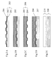
- Fig. 2 shows a conventional manufacturing process for a stamper.
- a conductive film 204 is formed by performing a conductive process in which nickel is sputtered on the surface of the patterns of pits and lands 202 that are formed on a glass substrate 201 included in a master disk 203 (Fig. 2A).
- an electroformed film (I) 205 is formed by electroforming nickel on the conductive film 204 (Fig. 2B).
- the conductive film 204 and the electroformed film (I) 205 are separated as a unitary member from the master disk 203 so as to produce a father stamper 206 (Fig. 2C).
- an electroformed film (II) 207 is formed by performing electroforming on the surface of the father stamper 206 (Fig. 2D). Then, a mother stamper 208 will be achieved by separating the electroformed film (II) 207 from the father stamper 206 (Fig. 2E). By applying a method such as injection molding to the mother stamper 208, the substrate of an optical disk 210 can be mass produced. In the above-mentioned method of manufacturing the stamper, nickel is used as a material for the conductive film and the electroformed film.
- the film (II) 207 may become integral with the conductive film 204 and cannot be separated from each other. This is because the electroformed film (II) 207 is formed by electroforming nickel on the surface of the conductive film 204 which also contains nickel itself, and this means both the film (II) 207 and the conductive film 204 are composed of the same metal.
- a method for manufacturing a stamper according to the present invention includes the steps of performing a plasma surface treatment on a surface of a father stamper having patterns of pits and lands, forming a nickel electroformed film on the surface of the father stamper, and forming a second stamper by separating the nickel electroformed film from the father stamper.
- this father stamper having improved flatness and smoothness when forming the electroformed film, the separability between the father stamper and the electroformed film improves.
- Ar gas is used during the plasma surface treatment, because using Ar gas resolves the conventional problems caused by use of oxygen gas.
- electric power from a RF power source for the plasma surface treatment is within a range between 50W and 500W. In this range, surface roughness of the father stamper is reduced, and as a result, the separability between the father stamper and the electroformed film is improved.
- a contact angle between the surface of the father stamper 106 and water on the surface thereof after performing the plasma surface treatment is smaller by 20 degrees or more compared to the contact angle before the plasma surface treatment. In this case, surface roughness of the father stamper is reduced, and as a result, the separability between the father stamper and the electroformed film is improved.
- the manufacturing process may also comprise the step of supplying water to the surface of the father stamper after performing the plasma surface treatment and before forming the electroformed film.
- the water supply step begins within 30 minutes after performing the plasma surface treatment. This is because it is necessary to form a film of nickel hydroxide on the surface of the father stamper before nickel oxide can be formed.
- the water supply step is performed by immersing the father stamper in water.
- the water supply may be performed by slowly introducing vapor into the chamber in which the plasma surface treatment is performed on the surface of the father stamper.
- the manufacturing process may also comprise forming a film on the surface of the father stamper in which the main component is nickel hydroxide. This film is made after performing the plasma surface treatment, and before forming the electroformed film. This is because the separability between the father stamper and the electroformed film is improved by forming the nickel hydroxide between the stamper and the film.
- the separability between the father stamper and a mother stamper formed by electroforming can be improved, thereby reducing defects in the mother stamper.
- the invention relates to a method for manufacturing a stamper to produce an optical disk.
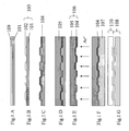
- Fig. 1A shows a glass substrate 101 onto which a photoresist is deposited.
- the process of forming the substrate 101 with the photoresist will now be explained.
- the glass substrate 101 having a diameter of 200nm and a thickness of 6mm and with its surface polished, is set on a turn table of a spin coating device.
- a photoresist layer 109 is formed having a thickness of about 28 ⁇ m.
- Fig. 1B shows a master disk 103 consisting of the glass substrate 101 on which patterns of pits and lands 102 have been formed by exposure and development processes.
- the process of forming the master disk 103 will now be explained.
- an optical laser with 250 nm wavelength converged by an object lens is applied to the photoresist layer 109, and a groove having a track pitch of 0.32 ⁇ m and a width of 0.15 ⁇ m is formed on the area of the photoresist layer 109 that is exposed to the laser (herein called the exposed area).
- the glass substrate 101 and the photoresist layer 109 including the exposed area is transferred to a development device.
- the photoresist layer 109 is developed using a developing solution, and the solution is washed away with purified water.
- the exposed area of the photoresist layer 109 is eliminated during the exposure process, and the non-exposed area of the photoresist layer 109 remains.
- the glass substrate 101 has only the non-exposed area after the development process and the desired pattern of pits and lands on the father stamper 106 is eliminated.
- the process described above is an example of using a positive photoresist, however, a negative photoresist may also be available.
- Fig. 1 C shows the master disk 103 with a conductive film 104.
- the process of forming the conductive film 104 on the master disk 103 will now be explained.
- the nickel conductive film 104 is formed to a thickness of 20nm on the master disk 103 using a sputtering method.
- Fig. 1D shows the master disk 103 on which an electroformed film (I) 105 is electroformed.
- the process of electroforming will now be explained.
- the glass substrate 101 having the conductive film 104 is set on a negative electrode system of a electroforming device (not shown) and then, the nickel electroforming is performed on the surface of the conductive film 104.
- the electroformed film (I) 105 in which the patterns of pits and lands 102 have been transcribed is formed.
- the electroformed film (I) 105 has a thickness of 0.3 mm
- the nickel electroforming is finished and the glass substrate 101 is detached from the negative electrode system of the electroforming device.
- the electroformed film (I) 105 and the conductive film 104 are separated from the master disk 103 in a unitary state so as to produce a father stamper 106.
- the contact angle between the surface of the father stamper 106 i.e. the side of the father stamper 106 having the surface of the conductive film 104
- water on the surface thereof will be measured before performing an etching step (described later) using a measuring instrument for the contact angle, and the result should be recorded (the contact angle may be 50 degrees, for example).
- Fig. 1E shows the process of eliminating the nickel oxidation film by performing the plasma surface treatment on the surface of the father stamper 106 (the side of the surface of the conductive film 104).
- the father stamper 106 is inserted in a parallel plate etching device (not shown), and the device is evacuated using a cryopump or the like.
- the ultimate vacuum is 3 ⁇ 10 -4 (Pa).
- the ultimate vacuum before introducing etching gas it is preferable for the ultimate vacuum before introducing etching gas to be 1 ⁇ 10 -3 (Pa) or below.
- a vacuum exhaust is performed, and the pressure inside of the device is maintained at 10 (Pa).
- the voltage is increased to 100W, and the etching is performed for 90 sec.
- the father stamper 106 is rinsed with purified water for five minutes.
- a contact angle between the surface of the father stamper 106 and water on the surface thereof is measured using a measuring instrument for the contact angle.
- the contact angle between the surface of the father stamper and water on the surface thereof is decreased by 20 degrees or more after etching has been performed.
- the angle after the etching may be adjusted to 15 degrees.
- Fig. 1F shows the father stamper 106 on which a film (II) 107 is electroformed.
- the process of forming the electroformed film (II) 107 will now be explained.
- the father stamper 106 after the etching is set on a negative electrode system of an electroforming device and then, the electroformed film (II) 107 is formed (the process of forming an electroformed film).
- the electroformed film (II) 107 has a thickness of 0.3mm
- the nickel electroforming is finished and the glass substrate 101 is detached from the negative electrode system included in the electroforming device.
- the electroformed film (II) 107 is separated from the father stamper 106 (the separation process).
- the film (II) 107 can be cleanly separated from the father stamper 106 so as to produce a mother stamper 108 (Fig. 1 G) without defects or residue. Further, from this mother stamper 108, optical recording media such as an optical disk 110 is produced using an injection molding machine.
- the ratio of nickel oxide to nickel hydroxide on the father stamper is locally different, and the separability between the two is different. Therefore, the separability between the electroformed film (II) and the conductive film becomes irregular, which may cause defects on the mother stamper.
- the plasma surface treatment by performing the plasma surface treatment on the surface of the father stamper (the side of the surface of the conductive film 104), it is possible to eliminate the nickel oxide and the nickel hydroxide formed on the surface. Because the plasma surface treatment is performed in a vacuum, pure nickel is exposed on the surface by eliminating the nickel oxide and the nickel hydroxide. It is thought that by immersing the father stamper 106 in purified water within 30 minutes after the plasma surface treatment, the nickel hydroxide can be formed uniformly on the surface.
- hydrophilicity on the surface of the father stamper 106 improves by performing a plasma surface treatment.
- the improvement cannot be confirmed using devices such as a surface measuring instrument or an interatomic force microscope that can analyze the surface roughness by quantitative analysis, because the plasma surface treatment is performed under low energy conditions.
- the difference with or without the plasma surface treatment can be quantitatively measured by examining differences of contact angles with respect to water.
- the contact angle between the surface of the father stamper 106 and water on the surface thereof after performing the plasma surface treatment is decreased by 20 degrees or more compared to the contact angle before the treatment.
- the phenomenon in which the contact angle with respect to water becomes smaller indicates that the surface roughness of the father stamper 106 is improved. Therefore, a contact area of the father stamper 106 and the electroformed film (II) 107 can be smaller when electroforming after plasma surface treatment, with an improvement in flatness and smoothness, compared to that before the plasma surface treatment.
- the separation performance between the father stamper 106 and the electroforming film (II) 107 may also improve even due to the effect of reducing the contact area.
- the separability between the father stamper 106 and the electroformed film (II) 107 can be improved. It is found that this phenomenon depends on the input power of the etching as explained later. If the input power of the etching is too large, the surface roughness becomes worse. This surface roughness affects the quality of the mother stamper 108. With an optical disk employing a substrate having patterns of pits and lands which is produced from a stamper with such high surface roughness, C/N (carrier to noise ratio) becomes worse because the noise of the reproducing signal component increases during reproduction. On the contrary, if the input power of the etching is too small, the electroformed film (II) 107 cannot be separated from the father stamper 106, because improvement in flatness and smoothness by performing the plasma surface treatment cannot be expected.
- the term "Bad” in the separability column indicates etching conditions in which the electroformed film (II) 107 could not be separated from the father stamper 106, or conditions in which defects were produced on the electroformed film (II) 107.
- the term “Good” in the same column indicates conditions in which a mother stamper 108 without defects was produced.
- the mother stamper 108 is set on an injection molding machine, and then a substrate for an optical recording medium with a thickness of 1.1 mm is produced by transcribing patterns of the mother stamper 108 to a polycarbonate resin.
- the surface roughness of the mother stamper 108 is measured as noise on the optical information medium after transcription to the polycarbonate substrate, and thus it is necessary to measure the level of noise of the polycarbonate substrate.
- An aluminum reflection film is formed to a thickness of 20nm on the information area side on the polycarbonate substrate, and further, a sheet containing polycarbonate with a thickness of 0.1 mm is formed on the reflection film.
- the substrate is set on an information reproducing device, and the level of noise is measured.
- an optical system which employs a wavelength of 405 nm and an object lens with a numerical aperture of 0.85.
- Light for reproducing information is applied to the substrate from the side of the polycarbonate sheet with a thickness of 0.1 mm.
- the output signal is set into a spectral analyzer and the level of noise in the 3 MHz broadband was investigated.
- the noise is -70dBm or below. From this examination, input power of the etching should be within the range of 50W and 500W.
- the contact angle between the father stamper 106 and water on the surface thereof is measured before and after etching, using a contact angle measurement instrument. From the results, it was found that, before and after etching, as the angle changed, the separability of the electroformed film (II) 107 depends largely on the contact angle with respect to water on the surface of the father stamper 106. On the other hand, because the contact angle with respect to water on the surface of the father stamper 106 can be controlled by manipulating the pressure of Ar gas and voltage applied when performing the etching, stampers were prepared that have different contact angles with respect to water on the surface of the father stamper 106 before and after etching.
- the separability column shows the separability of the electroformed film (II) 107 and the existence of defects. From the results, a decrease in the degree of the contact angle with respect to water on the surface of the father stamper 106 should be 20 degrees or more.
- Example 2 a mother stamper 108 will be formed via the same steps and procedures as described above. Fig. 1 will be used to describe this.
- the time that the father stamper 106 is left in the atmosphere after the plasma surface treatment is 30 minutes or less.
- the mother stamper 108 was formed using the same process as described above, without immersing the stamper in purified water after the plasma surface treatment. Instead of the immersing process, the pressure inside the chamber used for the plasma surface treatment of the father stamper 106 is returned to atmospheric pressure by applying vapor after the plasma surface treatment. According to this process, on the surface of the father stamper 106, nickel hydroxide of very high purity is formed. Note that it is also preferable that the process is performed within 30 minutes after the plasma treatment.
- the method for manufacturing a stamper of this invention is useful as a stamper production method for optical recording media and the like. In addition, it may be applied to a manufacturing method of a stamper produced by electroforming
Landscapes
- Engineering & Computer Science (AREA)
- Chemical & Material Sciences (AREA)
- Manufacturing & Machinery (AREA)
- Chemical Kinetics & Catalysis (AREA)
- Electrochemistry (AREA)
- Materials Engineering (AREA)
- Metallurgy (AREA)
- Organic Chemistry (AREA)
- Mechanical Engineering (AREA)
- Manufacturing Optical Record Carriers (AREA)
- Moulds For Moulding Plastics Or The Like (AREA)
Applications Claiming Priority (2)
| Application Number | Priority Date | Filing Date | Title |
|---|---|---|---|
| JP2003309174 | 2003-09-01 | ||
| JP2003309174 | 2003-09-01 |
Publications (2)
| Publication Number | Publication Date |
|---|---|
| EP1510599A2 true EP1510599A2 (de) | 2005-03-02 |
| EP1510599A3 EP1510599A3 (de) | 2007-01-03 |
Family
ID=34101291
Family Applications (1)
| Application Number | Title | Priority Date | Filing Date |
|---|---|---|---|
| EP04016511A Withdrawn EP1510599A3 (de) | 2003-09-01 | 2004-07-14 | Herstellungsverfahren einer Matrize, Matrize und optische Aufzeichnungsträger |
Country Status (5)
| Country | Link |
|---|---|
| US (1) | US20050045481A1 (de) |
| EP (1) | EP1510599A3 (de) |
| KR (1) | KR20050025246A (de) |
| CN (1) | CN1591632A (de) |
| TW (1) | TW200511296A (de) |
Cited By (1)
| Publication number | Priority date | Publication date | Assignee | Title |
|---|---|---|---|---|
| EP4151776A1 (de) * | 2021-09-17 | 2023-03-22 | FUJIFILM Corporation | Galvanoplastik-master, verfahren zur herstellung des galvanoplastik-masters und verfahren zur herstellung eines galvanoplastik-materials |
Families Citing this family (21)
| Publication number | Priority date | Publication date | Assignee | Title |
|---|---|---|---|---|
| KR100448452B1 (ko) | 2000-06-09 | 2004-09-13 | 엘지전자 주식회사 | 고밀도 광 기록매체의 메뉴 지원방법 |
| JP4147753B2 (ja) * | 2001-07-02 | 2008-09-10 | ソニー株式会社 | 光情報記録媒体、光情報記録媒体用原盤およびその製造方法 |
| RU2346340C2 (ru) * | 2002-10-02 | 2009-02-10 | Эл Джи Электроникс Инк. | Носитель записи со структурой данных для управления воспроизведением графических данных и способы и устройства записи и воспроизведения |
| EP1547080B1 (de) * | 2002-10-04 | 2012-01-25 | LG Electronics, Inc. | Aufzeichnungsmedium mit einer datenstruktur zur verwaltung der wiedergabe von grafikdaten und aufzeichnungs- und wiedergabeverfahren und -vorrichtungen |
| EP1618562A4 (de) * | 2003-04-29 | 2011-03-16 | Lg Electronics Inc | Aufzeichnungsmedium mit einer datenstruktur zur verwaltung der wiedergabe von grafischen daten und verfahren und vorrichtungen zum aufzeichnen und wiedergeben |
| US7616865B2 (en) * | 2003-04-30 | 2009-11-10 | Lg Electronics Inc. | Recording medium having a data structure for managing reproduction of subtitle data and methods and apparatuses of recording and reproducing |
| KR20050005074A (ko) * | 2003-07-01 | 2005-01-13 | 엘지전자 주식회사 | 고밀도 광디스크의 그래픽 데이터 관리방법 및 그에 따른고밀도 광디스크 |
| KR20050004339A (ko) * | 2003-07-02 | 2005-01-12 | 엘지전자 주식회사 | 고밀도 광디스크의 그래픽 데이터 관리방법 및 그에 따른고밀도 광디스크 |
| KR20050064150A (ko) * | 2003-12-23 | 2005-06-29 | 엘지전자 주식회사 | 고밀도 광디스크의 메뉴 구성방법 및 실행방법과기록재생장치 |
| US8545030B2 (en) | 2004-07-12 | 2013-10-01 | Gentex Corporation | Rearview mirror assemblies with anisotropic polymer laminates |
| JP2006277817A (ja) * | 2005-03-29 | 2006-10-12 | Fuji Photo Film Co Ltd | 磁気転写用マスターディスクの製造方法 |
| US20080248334A1 (en) * | 2007-03-30 | 2008-10-09 | Fujifilm Corporation | Mold structure, imprinting method using the same, magnetic recording medium and production method thereof |
| JP2009084644A (ja) * | 2007-09-28 | 2009-04-23 | Toshiba Corp | スタンパの製造方法およびスタンパ |
| JP4850817B2 (ja) * | 2007-11-29 | 2012-01-11 | 富士フイルム株式会社 | 磁気転写用マスターディスクの製造方法 |
| JP2009277335A (ja) * | 2008-04-18 | 2009-11-26 | Fujifilm Corp | スタンパの製造方法およびスタンパを用いた光情報記録媒体の製造方法 |
| JP2010077476A (ja) * | 2008-09-25 | 2010-04-08 | Toshiba Corp | スタンパの製造方法 |
| KR101079369B1 (ko) * | 2008-11-12 | 2011-11-02 | 삼성전기주식회사 | 프로브카드용 프로브 핀 제조방법 |
| US20120297856A1 (en) * | 2010-02-05 | 2012-11-29 | Obducat Ab | Method and process for metallic stamp replication for large area nanopatterns |
| US9145323B2 (en) * | 2013-01-21 | 2015-09-29 | Corning Incorporated | Molds for shaping glass and methods for making the same |
| CN108249390A (zh) * | 2018-01-17 | 2018-07-06 | 高世雄 | 一种在聚酰亚胺薄膜表面制作微纳结构的方法 |
| KR102164792B1 (ko) * | 2018-12-24 | 2020-10-14 | 한국기초과학지원연구원 | 마이크로니들 패치의 제조방법, 그에 의해 제조된 마이크로니들 및 마이크로니들 패치를 포함하는 물질 전달 시스템 |
Family Cites Families (6)
| Publication number | Priority date | Publication date | Assignee | Title |
|---|---|---|---|---|
| US2399267A (en) * | 1940-07-27 | 1946-04-30 | Solventol Chemical Products In | Cleaning method |
| JPS5952715B2 (ja) * | 1977-09-05 | 1984-12-21 | ソニー株式会社 | メツキ方法 |
| JPS5828838A (ja) * | 1981-08-14 | 1983-02-19 | Comput Basic Mach Technol Res Assoc | 薄膜磁気ヘッドの製造方法 |
| JPS59173288A (ja) * | 1983-03-22 | 1984-10-01 | Fujitsu Ltd | 電鋳金型の製造方法 |
| US5401350A (en) * | 1993-03-08 | 1995-03-28 | Lsi Logic Corporation | Coil configurations for improved uniformity in inductively coupled plasma systems |
| FR2751128B1 (fr) * | 1996-07-09 | 1998-09-11 | Commissariat Energie Atomique | Procede de nettoyage de surfaces metalliques par plasma |
-
2004
- 2004-06-24 TW TW093118278A patent/TW200511296A/zh unknown
- 2004-07-06 CN CNA2004100634357A patent/CN1591632A/zh active Pending
- 2004-07-08 US US10/885,970 patent/US20050045481A1/en not_active Abandoned
- 2004-07-14 EP EP04016511A patent/EP1510599A3/de not_active Withdrawn
- 2004-07-28 KR KR1020040059169A patent/KR20050025246A/ko not_active Withdrawn
Cited By (1)
| Publication number | Priority date | Publication date | Assignee | Title |
|---|---|---|---|---|
| EP4151776A1 (de) * | 2021-09-17 | 2023-03-22 | FUJIFILM Corporation | Galvanoplastik-master, verfahren zur herstellung des galvanoplastik-masters und verfahren zur herstellung eines galvanoplastik-materials |
Also Published As
| Publication number | Publication date |
|---|---|
| KR20050025246A (ko) | 2005-03-14 |
| EP1510599A3 (de) | 2007-01-03 |
| CN1591632A (zh) | 2005-03-09 |
| TW200511296A (en) | 2005-03-16 |
| US20050045481A1 (en) | 2005-03-03 |
Similar Documents
| Publication | Publication Date | Title |
|---|---|---|
| EP1510599A2 (de) | Herstellungsverfahren einer Matrize, Matrize und optische Aufzeichnungsträger | |
| US20050151283A1 (en) | Method and apparatus for making a stamper for patterning CDs and DVDs | |
| US4259433A (en) | Method for producing disk-recording plates | |
| JP2005070650A (ja) | レジストパターン形成方法 | |
| TWI258142B (en) | Manufacturing method of stamper for manufacturing data medium, the stamper, and the stamper spacer with template | |
| JP3448661B2 (ja) | 光ディスク用合成石英型及び光ディスク | |
| JP2000280255A (ja) | 原盤の製造方法 | |
| US7204188B2 (en) | Method of manufacturing stamper for manufacturing information medium, stamper, and photoresist master | |
| EP1460626A1 (de) | Verfahren zur herstellung eines stanzers für die herstellung eines informationsmediums, stanzer und fotoresist-originalplatte | |
| JPH10241213A (ja) | 光ディスク用スタンパーの製造方法 | |
| JP2005100597A (ja) | スタンパの製造方法、スタンパおよび光記録媒体 | |
| JPH11350181A (ja) | スタンパの製造方法 | |
| JPH05205321A (ja) | スタンパの製造方法 | |
| JP3749520B2 (ja) | 情報媒体製造用スタンパの製造方法、スタンパ、及び原盤付スタンパ中間体 | |
| KR20050042804A (ko) | 광 기록 매체와 그 제조 방법 | |
| JP2663912B2 (ja) | ディスクの製造方法 | |
| US20040166446A1 (en) | Method for manufacturing metal master of information recording disc and metal master | |
| JPH0283835A (ja) | 光ディスク成形用スタンパ | |
| JPS6177152A (ja) | 光デイスク用スタンパの製作法 | |
| JPS60197959A (ja) | 光デイスクの製造方法 | |
| JPH04307442A (ja) | 光学式記録媒体の製造方法 | |
| JPH06349115A (ja) | スタンパーの製造方法 | |
| JPH09161336A (ja) | 光記録媒体用スタンパの製造方法 | |
| JP2006323927A (ja) | 光情報記録媒体製造用原盤並びにスタンパの製造方法 | |
| JPH01235044A (ja) | 光ディスク基板およびその製造方法 |
Legal Events
| Date | Code | Title | Description |
|---|---|---|---|
| PUAI | Public reference made under article 153(3) epc to a published international application that has entered the european phase |
Free format text: ORIGINAL CODE: 0009012 |
|
| AK | Designated contracting states |
Kind code of ref document: A2 Designated state(s): AT BE BG CH CY CZ DE DK EE ES FI FR GB GR HU IE IT LI LU MC NL PL PT RO SE SI SK TR |
|
| AX | Request for extension of the european patent |
Extension state: AL HR LT LV MK |
|
| PUAL | Search report despatched |
Free format text: ORIGINAL CODE: 0009013 |
|
| AK | Designated contracting states |
Kind code of ref document: A3 Designated state(s): AT BE BG CH CY CZ DE DK EE ES FI FR GB GR HU IE IT LI LU MC NL PL PT RO SE SI SK TR |
|
| AX | Request for extension of the european patent |
Extension state: AL HR LT LV MK |
|
| RIC1 | Information provided on ipc code assigned before grant |
Ipc: G11B 7/26 20060101ALI20061128BHEP Ipc: C25D 1/22 20060101AFI20041129BHEP |
|
| STAA | Information on the status of an ep patent application or granted ep patent |
Free format text: STATUS: THE APPLICATION HAS BEEN WITHDRAWN |
|
| 18W | Application withdrawn |
Effective date: 20061221 |