EP1557586B1 - Verfahren zur herstellung von torsionsdämpfern - Google Patents
Verfahren zur herstellung von torsionsdämpfern Download PDFInfo
- Publication number
- EP1557586B1 EP1557586B1 EP03799070A EP03799070A EP1557586B1 EP 1557586 B1 EP1557586 B1 EP 1557586B1 EP 03799070 A EP03799070 A EP 03799070A EP 03799070 A EP03799070 A EP 03799070A EP 1557586 B1 EP1557586 B1 EP 1557586B1
- Authority
- EP
- European Patent Office
- Prior art keywords
- annular
- hub
- silane coupling
- coupling agent
- rubber
- Prior art date
- Legal status (The legal status is an assumption and is not a legal conclusion. Google has not performed a legal analysis and makes no representation as to the accuracy of the status listed.)
- Expired - Lifetime
Links
- 238000000034 method Methods 0.000 title claims description 28
- 239000006087 Silane Coupling Agent Substances 0.000 claims description 45
- 238000001035 drying Methods 0.000 claims description 13
- 238000005461 lubrication Methods 0.000 claims description 12
- 238000003825 pressing Methods 0.000 claims description 8
- 239000000126 substance Substances 0.000 claims description 7
- 238000004381 surface treatment Methods 0.000 claims description 7
- 239000007788 liquid Substances 0.000 claims description 4
- 239000003795 chemical substances by application Substances 0.000 description 13
- 230000002093 peripheral effect Effects 0.000 description 13
- 239000003921 oil Substances 0.000 description 11
- 230000003247 decreasing effect Effects 0.000 description 9
- 150000004756 silanes Chemical class 0.000 description 5
- 239000012948 isocyanate Substances 0.000 description 4
- 238000004519 manufacturing process Methods 0.000 description 4
- 239000004902 Softening Agent Substances 0.000 description 3
- 239000007864 aqueous solution Substances 0.000 description 3
- 239000002184 metal Substances 0.000 description 3
- LFQSCWFLJHTTHZ-UHFFFAOYSA-N Ethanol Chemical compound CCO LFQSCWFLJHTTHZ-UHFFFAOYSA-N 0.000 description 2
- 230000000694 effects Effects 0.000 description 2
- 230000001965 increasing effect Effects 0.000 description 2
- 239000007769 metal material Substances 0.000 description 2
- 238000002156 mixing Methods 0.000 description 2
- 239000004014 plasticizer Substances 0.000 description 2
- 230000000630 rising effect Effects 0.000 description 2
- 238000006884 silylation reaction Methods 0.000 description 2
- WYTZZXDRDKSJID-UHFFFAOYSA-N (3-aminopropyl)triethoxysilane Chemical compound CCO[Si](OCC)(OCC)CCCN WYTZZXDRDKSJID-UHFFFAOYSA-N 0.000 description 1
- 125000000022 2-aminoethyl group Chemical group [H]C([*])([H])C([H])([H])N([H])[H] 0.000 description 1
- REWYMBAFAAYCAR-UHFFFAOYSA-N 3-[bis(2-methoxyethoxy)-phenylsilyl]propanoic acid Chemical compound COCCO[Si](CCC(O)=O)(OCCOC)C1=CC=CC=C1 REWYMBAFAAYCAR-UHFFFAOYSA-N 0.000 description 1
- PZOOCLZALKVNIT-UHFFFAOYSA-N 3-[diethoxy(3-phenylpropoxy)silyl]-n-ethenylpropan-1-amine Chemical compound C=CNCCC[Si](OCC)(OCC)OCCCC1=CC=CC=C1 PZOOCLZALKVNIT-UHFFFAOYSA-N 0.000 description 1
- HXLAEGYMDGUSBD-UHFFFAOYSA-N 3-[diethoxy(methyl)silyl]propan-1-amine Chemical compound CCO[Si](C)(OCC)CCCN HXLAEGYMDGUSBD-UHFFFAOYSA-N 0.000 description 1
- MBNRBJNIYVXSQV-UHFFFAOYSA-N 3-[diethoxy(methyl)silyl]propane-1-thiol Chemical compound CCO[Si](C)(OCC)CCCS MBNRBJNIYVXSQV-UHFFFAOYSA-N 0.000 description 1
- ZYAASQNKCWTPKI-UHFFFAOYSA-N 3-[dimethoxy(methyl)silyl]propan-1-amine Chemical compound CO[Si](C)(OC)CCCN ZYAASQNKCWTPKI-UHFFFAOYSA-N 0.000 description 1
- IKYAJDOSWUATPI-UHFFFAOYSA-N 3-[dimethoxy(methyl)silyl]propane-1-thiol Chemical compound CO[Si](C)(OC)CCCS IKYAJDOSWUATPI-UHFFFAOYSA-N 0.000 description 1
- OXYZDRAJMHGSMW-UHFFFAOYSA-N 3-chloropropyl(trimethoxy)silane Chemical compound CO[Si](OC)(OC)CCCCl OXYZDRAJMHGSMW-UHFFFAOYSA-N 0.000 description 1
- DCQBZYNUSLHVJC-UHFFFAOYSA-N 3-triethoxysilylpropane-1-thiol Chemical compound CCO[Si](OCC)(OCC)CCCS DCQBZYNUSLHVJC-UHFFFAOYSA-N 0.000 description 1
- AXEFESAPMLYPEF-UHFFFAOYSA-N 3-triethoxysilylpropanoic acid Chemical compound CCO[Si](OCC)(OCC)CCC(O)=O AXEFESAPMLYPEF-UHFFFAOYSA-N 0.000 description 1
- SJECZPVISLOESU-UHFFFAOYSA-N 3-trimethoxysilylpropan-1-amine Chemical compound CO[Si](OC)(OC)CCCN SJECZPVISLOESU-UHFFFAOYSA-N 0.000 description 1
- UUEWCQRISZBELL-UHFFFAOYSA-N 3-trimethoxysilylpropane-1-thiol Chemical compound CO[Si](OC)(OC)CCCS UUEWCQRISZBELL-UHFFFAOYSA-N 0.000 description 1
- LVACOMKKELLCHJ-UHFFFAOYSA-N 3-trimethoxysilylpropylurea Chemical compound CO[Si](OC)(OC)CCCNC(N)=O LVACOMKKELLCHJ-UHFFFAOYSA-N 0.000 description 1
- QGIPACNZBRJHAV-UHFFFAOYSA-N 4-[diethoxy(methyl)silyl]oxypentyl prop-2-enoate Chemical compound CCO[Si](C)(OCC)OC(C)CCCOC(=O)C=C QGIPACNZBRJHAV-UHFFFAOYSA-N 0.000 description 1
- 239000007983 Tris buffer Substances 0.000 description 1
- NOKSMMGULAYSTD-UHFFFAOYSA-N [SiH4].N=C=O Chemical compound [SiH4].N=C=O NOKSMMGULAYSTD-UHFFFAOYSA-N 0.000 description 1
- 230000001476 alcoholic effect Effects 0.000 description 1
- 150000001343 alkyl silanes Chemical class 0.000 description 1
- 125000003277 amino group Chemical group 0.000 description 1
- 125000002490 anilino group Chemical group [H]N(*)C1=C([H])C([H])=C([H])C([H])=C1[H] 0.000 description 1
- 150000004945 aromatic hydrocarbons Chemical class 0.000 description 1
- 230000000052 comparative effect Effects 0.000 description 1
- 150000001875 compounds Chemical class 0.000 description 1
- 230000006835 compression Effects 0.000 description 1
- 238000007906 compression Methods 0.000 description 1
- 238000013016 damping Methods 0.000 description 1
- 238000005238 degreasing Methods 0.000 description 1
- UJTGYJODGVUOGO-UHFFFAOYSA-N diethoxy-methyl-propylsilane Chemical compound CCC[Si](C)(OCC)OCC UJTGYJODGVUOGO-UHFFFAOYSA-N 0.000 description 1
- 238000007865 diluting Methods 0.000 description 1
- 230000002708 enhancing effect Effects 0.000 description 1
- 125000003700 epoxy group Chemical group 0.000 description 1
- FWDBOZPQNFPOLF-UHFFFAOYSA-N ethenyl(triethoxy)silane Chemical compound CCO[Si](OCC)(OCC)C=C FWDBOZPQNFPOLF-UHFFFAOYSA-N 0.000 description 1
- NKSJNEHGWDZZQF-UHFFFAOYSA-N ethenyl(trimethoxy)silane Chemical compound CO[Si](OC)(OC)C=C NKSJNEHGWDZZQF-UHFFFAOYSA-N 0.000 description 1
- 229910052736 halogen Inorganic materials 0.000 description 1
- 150000002367 halogens Chemical class 0.000 description 1
- 238000006459 hydrosilylation reaction Methods 0.000 description 1
- 238000007654 immersion Methods 0.000 description 1
- 239000004615 ingredient Substances 0.000 description 1
- IQPQWNKOIGAROB-UHFFFAOYSA-N isocyanate group Chemical group [N-]=C=O IQPQWNKOIGAROB-UHFFFAOYSA-N 0.000 description 1
- -1 isocyanurate silanes Chemical class 0.000 description 1
- ZFSLODLOARCGLH-UHFFFAOYSA-N isocyanuric acid Chemical compound OC1=NC(O)=NC(O)=N1 ZFSLODLOARCGLH-UHFFFAOYSA-N 0.000 description 1
- 239000000314 lubricant Substances 0.000 description 1
- 239000000463 material Substances 0.000 description 1
- INJVFBCDVXYHGQ-UHFFFAOYSA-N n'-(3-triethoxysilylpropyl)ethane-1,2-diamine Chemical compound CCO[Si](OCC)(OCC)CCCNCCN INJVFBCDVXYHGQ-UHFFFAOYSA-N 0.000 description 1
- PHQOGHDTIVQXHL-UHFFFAOYSA-N n'-(3-trimethoxysilylpropyl)ethane-1,2-diamine Chemical compound CO[Si](OC)(OC)CCCNCCN PHQOGHDTIVQXHL-UHFFFAOYSA-N 0.000 description 1
- YLBPOJLDZXHVRR-UHFFFAOYSA-N n'-[3-[diethoxy(methyl)silyl]propyl]ethane-1,2-diamine Chemical compound CCO[Si](C)(OCC)CCCNCCN YLBPOJLDZXHVRR-UHFFFAOYSA-N 0.000 description 1
- MQWFLKHKWJMCEN-UHFFFAOYSA-N n'-[3-[dimethoxy(methyl)silyl]propyl]ethane-1,2-diamine Chemical compound CO[Si](C)(OC)CCCNCCN MQWFLKHKWJMCEN-UHFFFAOYSA-N 0.000 description 1
- KBJFYLLAMSZSOG-UHFFFAOYSA-N n-(3-trimethoxysilylpropyl)aniline Chemical compound CO[Si](OC)(OC)CCCNC1=CC=CC=C1 KBJFYLLAMSZSOG-UHFFFAOYSA-N 0.000 description 1
- DRRZZMBHJXLZRS-UHFFFAOYSA-N n-[3-[dimethoxy(methyl)silyl]propyl]cyclohexanamine Chemical compound CO[Si](C)(OC)CCCNC1CCCCC1 DRRZZMBHJXLZRS-UHFFFAOYSA-N 0.000 description 1
- CLYWMXVFAMGARU-UHFFFAOYSA-N n-benzyl-3-trimethoxysilylpropan-1-amine Chemical compound CO[Si](OC)(OC)CCCNCC1=CC=CC=C1 CLYWMXVFAMGARU-UHFFFAOYSA-N 0.000 description 1
- 150000001282 organosilanes Chemical class 0.000 description 1
- 150000003021 phthalic acid derivatives Chemical class 0.000 description 1
- 229920000728 polyester Polymers 0.000 description 1
- 229920001296 polysiloxane Polymers 0.000 description 1
- 125000002924 primary amino group Chemical group [H]N([H])* 0.000 description 1
- FZHAPNGMFPVSLP-UHFFFAOYSA-N silanamine Chemical class [SiH3]N FZHAPNGMFPVSLP-UHFFFAOYSA-N 0.000 description 1
- ACECBHHKGNTVPB-UHFFFAOYSA-N silylformic acid Chemical class OC([SiH3])=O ACECBHHKGNTVPB-UHFFFAOYSA-N 0.000 description 1
- 239000007921 spray Substances 0.000 description 1
- 125000003396 thiol group Chemical group [H]S* 0.000 description 1
- NBXZNTLFQLUFES-UHFFFAOYSA-N triethoxy(propyl)silane Chemical compound CCC[Si](OCC)(OCC)OCC NBXZNTLFQLUFES-UHFFFAOYSA-N 0.000 description 1
- UDUKMRHNZZLJRB-UHFFFAOYSA-N triethoxy-[2-(7-oxabicyclo[4.1.0]heptan-4-yl)ethyl]silane Chemical compound C1C(CC[Si](OCC)(OCC)OCC)CCC2OC21 UDUKMRHNZZLJRB-UHFFFAOYSA-N 0.000 description 1
- JXUKBNICSRJFAP-UHFFFAOYSA-N triethoxy-[3-(oxiran-2-ylmethoxy)propyl]silane Chemical compound CCO[Si](OCC)(OCC)CCCOCC1CO1 JXUKBNICSRJFAP-UHFFFAOYSA-N 0.000 description 1
- HQYALQRYBUJWDH-UHFFFAOYSA-N trimethoxy(propyl)silane Chemical compound CCC[Si](OC)(OC)OC HQYALQRYBUJWDH-UHFFFAOYSA-N 0.000 description 1
- DQZNLOXENNXVAD-UHFFFAOYSA-N trimethoxy-[2-(7-oxabicyclo[4.1.0]heptan-4-yl)ethyl]silane Chemical compound C1C(CC[Si](OC)(OC)OC)CCC2OC21 DQZNLOXENNXVAD-UHFFFAOYSA-N 0.000 description 1
- BPSIOYPQMFLKFR-UHFFFAOYSA-N trimethoxy-[3-(oxiran-2-ylmethoxy)propyl]silane Chemical compound CO[Si](OC)(OC)CCCOCC1CO1 BPSIOYPQMFLKFR-UHFFFAOYSA-N 0.000 description 1
- PZJJKWKADRNWSW-UHFFFAOYSA-N trimethoxysilicon Chemical group CO[Si](OC)OC PZJJKWKADRNWSW-UHFFFAOYSA-N 0.000 description 1
- 125000000391 vinyl group Chemical group [H]C([*])=C([H])[H] 0.000 description 1
- 229920002554 vinyl polymer Polymers 0.000 description 1
Images

Classifications
-
- F—MECHANICAL ENGINEERING; LIGHTING; HEATING; WEAPONS; BLASTING
- F16—ENGINEERING ELEMENTS AND UNITS; GENERAL MEASURES FOR PRODUCING AND MAINTAINING EFFECTIVE FUNCTIONING OF MACHINES OR INSTALLATIONS; THERMAL INSULATION IN GENERAL
- F16F—SPRINGS; SHOCK-ABSORBERS; MEANS FOR DAMPING VIBRATION
- F16F15/00—Suppression of vibrations in systems; Means or arrangements for avoiding or reducing out-of-balance forces, e.g. due to motion
- F16F15/10—Suppression of vibrations in rotating systems by making use of members moving with the system
- F16F15/12—Suppression of vibrations in rotating systems by making use of members moving with the system using elastic members or friction-damping members, e.g. between a rotating shaft and a gyratory mass mounted thereon
- F16F15/121—Suppression of vibrations in rotating systems by making use of members moving with the system using elastic members or friction-damping members, e.g. between a rotating shaft and a gyratory mass mounted thereon using springs as elastic members, e.g. metallic springs
- F16F15/124—Elastomeric springs
- F16F15/126—Elastomeric springs consisting of at least one annular element surrounding the axis of rotation
-
- F—MECHANICAL ENGINEERING; LIGHTING; HEATING; WEAPONS; BLASTING
- F16—ENGINEERING ELEMENTS AND UNITS; GENERAL MEASURES FOR PRODUCING AND MAINTAINING EFFECTIVE FUNCTIONING OF MACHINES OR INSTALLATIONS; THERMAL INSULATION IN GENERAL
- F16H—GEARING
- F16H55/00—Elements with teeth or friction surfaces for conveying motion; Worms, pulleys or sheaves for gearing mechanisms
- F16H55/32—Friction members
- F16H55/36—Pulleys
-
- F—MECHANICAL ENGINEERING; LIGHTING; HEATING; WEAPONS; BLASTING
- F16—ENGINEERING ELEMENTS AND UNITS; GENERAL MEASURES FOR PRODUCING AND MAINTAINING EFFECTIVE FUNCTIONING OF MACHINES OR INSTALLATIONS; THERMAL INSULATION IN GENERAL
- F16F—SPRINGS; SHOCK-ABSORBERS; MEANS FOR DAMPING VIBRATION
- F16F2226/00—Manufacturing; Treatments
- F16F2226/04—Assembly or fixing methods; methods to form or fashion parts
- F16F2226/045—Press-fitting
-
- F—MECHANICAL ENGINEERING; LIGHTING; HEATING; WEAPONS; BLASTING
- F16—ENGINEERING ELEMENTS AND UNITS; GENERAL MEASURES FOR PRODUCING AND MAINTAINING EFFECTIVE FUNCTIONING OF MACHINES OR INSTALLATIONS; THERMAL INSULATION IN GENERAL
- F16H—GEARING
- F16H55/00—Elements with teeth or friction surfaces for conveying motion; Worms, pulleys or sheaves for gearing mechanisms
- F16H55/32—Friction members
- F16H55/36—Pulleys
- F16H2055/366—Pulleys with means providing resilience or vibration damping
-
- Y—GENERAL TAGGING OF NEW TECHNOLOGICAL DEVELOPMENTS; GENERAL TAGGING OF CROSS-SECTIONAL TECHNOLOGIES SPANNING OVER SEVERAL SECTIONS OF THE IPC; TECHNICAL SUBJECTS COVERED BY FORMER USPC CROSS-REFERENCE ART COLLECTIONS [XRACs] AND DIGESTS
- Y10—TECHNICAL SUBJECTS COVERED BY FORMER USPC
- Y10T—TECHNICAL SUBJECTS COVERED BY FORMER US CLASSIFICATION
- Y10T29/00—Metal working
- Y10T29/49—Method of mechanical manufacture
- Y10T29/49609—Spring making
- Y10T29/49615—Resilient shock or vibration absorber utility
-
- Y—GENERAL TAGGING OF NEW TECHNOLOGICAL DEVELOPMENTS; GENERAL TAGGING OF CROSS-SECTIONAL TECHNOLOGIES SPANNING OVER SEVERAL SECTIONS OF THE IPC; TECHNICAL SUBJECTS COVERED BY FORMER USPC CROSS-REFERENCE ART COLLECTIONS [XRACs] AND DIGESTS
- Y10—TECHNICAL SUBJECTS COVERED BY FORMER USPC
- Y10T—TECHNICAL SUBJECTS COVERED BY FORMER US CLASSIFICATION
- Y10T29/00—Metal working
- Y10T29/49—Method of mechanical manufacture
- Y10T29/49826—Assembling or joining
- Y10T29/49863—Assembling or joining with prestressing of part
- Y10T29/4987—Elastic joining of parts
- Y10T29/49872—Confining elastic part in socket
-
- Y—GENERAL TAGGING OF NEW TECHNOLOGICAL DEVELOPMENTS; GENERAL TAGGING OF CROSS-SECTIONAL TECHNOLOGIES SPANNING OVER SEVERAL SECTIONS OF THE IPC; TECHNICAL SUBJECTS COVERED BY FORMER USPC CROSS-REFERENCE ART COLLECTIONS [XRACs] AND DIGESTS
- Y10—TECHNICAL SUBJECTS COVERED BY FORMER USPC
- Y10T—TECHNICAL SUBJECTS COVERED BY FORMER US CLASSIFICATION
- Y10T29/00—Metal working
- Y10T29/49—Method of mechanical manufacture
- Y10T29/49826—Assembling or joining
- Y10T29/49885—Assembling or joining with coating before or during assembling
-
- Y—GENERAL TAGGING OF NEW TECHNOLOGICAL DEVELOPMENTS; GENERAL TAGGING OF CROSS-SECTIONAL TECHNOLOGIES SPANNING OVER SEVERAL SECTIONS OF THE IPC; TECHNICAL SUBJECTS COVERED BY FORMER USPC CROSS-REFERENCE ART COLLECTIONS [XRACs] AND DIGESTS
- Y10—TECHNICAL SUBJECTS COVERED BY FORMER USPC
- Y10T—TECHNICAL SUBJECTS COVERED BY FORMER US CLASSIFICATION
- Y10T29/00—Metal working
- Y10T29/49—Method of mechanical manufacture
- Y10T29/49826—Assembling or joining
- Y10T29/49945—Assembling or joining by driven force fit
-
- Y—GENERAL TAGGING OF NEW TECHNOLOGICAL DEVELOPMENTS; GENERAL TAGGING OF CROSS-SECTIONAL TECHNOLOGIES SPANNING OVER SEVERAL SECTIONS OF THE IPC; TECHNICAL SUBJECTS COVERED BY FORMER USPC CROSS-REFERENCE ART COLLECTIONS [XRACs] AND DIGESTS
- Y10—TECHNICAL SUBJECTS COVERED BY FORMER USPC
- Y10T—TECHNICAL SUBJECTS COVERED BY FORMER US CLASSIFICATION
- Y10T428/00—Stock material or miscellaneous articles
- Y10T428/29—Coated or structually defined flake, particle, cell, strand, strand portion, rod, filament, macroscopic fiber or mass thereof
- Y10T428/2982—Particulate matter [e.g., sphere, flake, etc.]
- Y10T428/2991—Coated
- Y10T428/2993—Silicic or refractory material containing [e.g., tungsten oxide, glass, cement, etc.]
- Y10T428/2995—Silane, siloxane or silicone coating
-
- Y—GENERAL TAGGING OF NEW TECHNOLOGICAL DEVELOPMENTS; GENERAL TAGGING OF CROSS-SECTIONAL TECHNOLOGIES SPANNING OVER SEVERAL SECTIONS OF THE IPC; TECHNICAL SUBJECTS COVERED BY FORMER USPC CROSS-REFERENCE ART COLLECTIONS [XRACs] AND DIGESTS
- Y10—TECHNICAL SUBJECTS COVERED BY FORMER USPC
- Y10T—TECHNICAL SUBJECTS COVERED BY FORMER US CLASSIFICATION
- Y10T74/00—Machine element or mechanism
- Y10T74/21—Elements
- Y10T74/2121—Flywheel, motion smoothing-type
- Y10T74/2131—Damping by absorbing vibration force [via rubber, elastomeric material, etc.]
Definitions
- the present invention relates to a torsional damper used for absorbing a torsional vibration generated at a rotary shaft such as a crankshaft of an engine or the like.
- the silane coupling agent has the problem that the silane coupling agent has a comparatively long predetermined time period after applying the agent until drying, and a press-in ability is decreased in the pressing of the annular rubber in immediately after applying the silane coupling agent since the agent becomes to have tackiness, and the rubber is pressed-in in the undulated state greatly. So, the durability of the torsional damper may be decreased.
- an organosilane has been used conventionally as a slip-proof agent and a lubricant in the press-in, as described in Japanese Patent Laid Open No. 2001-263423 (EP-A-1 176 337).
- EP-A-1 176 337 Japanese Patent Laid Open No. 2001-263423
- the press-in load in the press-in of the annular rubber is large, there are many residual stresses in the rubber, so that axial and radial run-out accuracy of the annular mass with respect to a hub bore portion is remarkably decreased.
- the present invention solves the above-mentioned problems, and has an object to provide a method of producing the torsional damper capable of preventing undulation of the rubber from occurring in the pressing of the annular rubber in between the hub and the annular mass, and improving strain durability of the torsional damper. Furthermore, the present invention also has an object to provide the method of producing the torsional damper capable of significantly decreasing the press-in load in the press-in of the annular rubber, and enhancing the axial and radial run-out accuracy of the annular mass with respect to the hub bore portion.
- a method of producing a torsional damper according to Claim 1 of the present invention where an annular rubber is pressed in an axial direction in between a hub and an annular mass, the method comprising, applying a silane coupling agent to faces of the hub and the annular mass between which faces the annular rubber is pressed in, leaving the silane coupling agent for a predetermined time period to be dried, applying a fitting liquid such as a lubrication oil or the like to the hub and one of the annular mass and the annular rubber, and pressing the annular rubber in between the hub and the annular mass.
- the method of producing the torsional damper according to Claim 2 of the present invention comprising, applying the silane coupling agent without carrying out a chemical surface treatment to the faces of the hub and the annular mass between which faces the annular rubber is pressed in, in the method according to Claim 1.
- the silane coupling agent When the silane coupling agent is applied to the faces of the hub and the annular mass between which faces the annular rubber is pressed in, and is left for the predetermined time period after the application, the silane coupling agent is dried, as the production method according to Claim 1 of the present invention having the above-mentioned constitutions.
- the predetermined time period from applying the agent until drying is about 2 hours suitably, although based on conditions.
- an amine-base or urethane-base silane coupling agent can be used.
- the amine-base silane coupling agent an amino group-containing silane coupling agent
- the following agents can be used, that is, ⁇ -aminopropyltrimethoxysilane, ⁇ -aminopropyltriethoxysilane, ⁇ -aminopropylmethyldimethoxysilane, ⁇ -aminopropylmethyldiethoxysilane, ⁇ -(2-aminoethyl)aminopropyltrimethoxysilane, ⁇ -(2-aminoethyl)aminopropylmethyldimethoxysilane, ⁇ -(2-aminoethyl)aminopropyltriethoxylsilane, ⁇ -(2-aminoethyl)aminopropylmethyldiethoxy silane, ⁇ -ureidopropyltrimethoxys
- urethane-base silane coupling agent isocyanate group-containing silane coupling agent
- the following agents can be used, that is, ⁇ -isocyanate propyltrimethoxysilane, ⁇ -isocyanate propyltriethoxysilane, ⁇ -isocyanate propylmethyldi methoxysilane, ⁇ -isocyanate propylmethyldiethoxy silane, or the like.
- a silane coupling agent other than the amine-base or urethane-base silane coupling agent can be used as an ingredient applied to the faces of the hub and the annular mass between which faces the annular rubber is pressed in.
- the following agents can be used, that is, mercapto group containing silanes, such as ⁇ -mercaptopropyl trimethoxysilane, ⁇ -mercaptopropyl triethoxysilane, ⁇ -mercaptopropylmethyldimethoxysilane, ⁇ -mercapto propyl methyldiethoxysilane or the like, epoxy group containing silanes, such as ⁇ -glycidoxypropyl trimethoxysilane, ⁇ -glycidoxypropyltriethoxysilane, ⁇ -glycidoxypropylmethldimethoxysilane, ⁇ -(3, 4-epoxycyclohexyl) ethyl trimethoxysilane, ⁇ -(3, 4-epoxycyclohexyl) ethyltriethoxysilane or the like, carboxysilanes, such as ⁇ -carboxyethyltrieth
- an amino-modified silylpolymer which is a derivative obtained by modifying these silanes, a hydrosilylation aminopolymer, an unsaturated aminosilane complex, a blocked isocyanate silane, a phenylamino long-chain alkylsilane, an amino silylation silicone, a silylation polyester or the like.
- silane coupling agents may be used with only one kind, they may be also used by mixing two kinds or more.
- an aromatic hydrocarbon compound a plasticizer, a softening agent or the like
- a plasticizer a phthalic acid derivative or the like
- a paraffinic softening agent or the like can be used.
- these lubrication oils may be used with only one kind, they may be used by mixing two kinds or more.
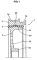
- FIG 1 shows the half-cut sectional view of a torsional damper 1 made by the production method according to the present invention.
- the toritional damper 1 comprises a hub 2 mounted on a crankshaft in an automobile engine or the like (not shown in the drawings), an annular mass 3 (also called to as a mass body) separately and concentrically disposed on the outer peripheral side of the hub 2, and an annular rubber 4 (also said to as elastic body) pressed in an axial direction and fixed between the opposed faces of the hub 2 and the annular mass 3.
- the torsional damper 1 has a constitution in which the hub 2 and the annular mass 3 are elastically connected each other through the annular rubber 4.
- the hub 2 is annularly molded with a predetermined metallic material, and integrally comprises a boss part 2a mounted on a shaft end of the crankshaft, a disc-formed rising part 2b integrally molded from the boss part 2a in a radially outward direction, and a rim part 2c integrally molded with an outer peripheral end part of the rising part 2b.
- the annular mass 3 is also annularly molded with a predetermined metallic material, and separately and concentrically disposed on the outer peripheral side of the rim part 2c, and a pulley groove 3a is formed at the outer peripheral face of the annular mass 3.
- the pulley groove 3a is prepared for transmitting a rotation torque of the crankshaft to various accessories via an endless belt.
- the annular rubber 4 is annularly formed with a predetermined rubber material, and is pressed in for fitting between the outer peripheral face of the rim part 2c in the hub 2 and the inner peripheral face of the annular mass 3 opposed to the hub 2 with necessary compression allowance.
- the silane coupling agent (not shown) is applied between the rim part 2c in the hub 2 and the annular hub 4, and the annular rubber 4 and the annular mass 3 respectively.
- the silane coupling agent has the excellent effect for increasing sliding torque in pressure contacting surface of the rubber and the metal. Since the hub 2, the annular rubber 4 and the annular mass 3 are strongly kept each other, and the sliding torque is remarkably increased, and thus it is possible to effectively prevent the occurring of sliding in the rotating direction between the rim part 2c in the hub 2 and the annular rubber 4, and the annular hub 4 and the annular mass 3, at the time of inputting large torque by a dynamic damping operation or the like of the damper 1.
- the silane coupling agent is a water-soluble agent, so that the agent is used after diluting with an aqueous solution, for example, an ethanol aqueous solution or the other alcoholic aqueous solution, when this agent is applied to the predetermined part in the production process of the damper 1.
- an aqueous solution for example, an ethanol aqueous solution or the other alcoholic aqueous solution
- the hub 2, the annular mass 3 and the annular rubber 4 are formed to each shape of the part respectively, and a degreasing treatment is carried out to the hub 2 and the annular mass 3.
- the annular mass 3 is set to the outer peripheral side of the hub 2 to press the annular rubber 4 in an axial direction in between the hub 2 and the annular mass 3.
- the silane coupling agent is applied to the faces 2d and 3b of the hub 2 and the annular mass 3 between which faces the annular rubber is pressed in, that is, the outer peripheral face of the rim part 2c of the hub 2 and the inner peripheral face of the annular mass 3 respectively.
- a spray method is suitably used for the application.
- the chemical surface treatment is not carried out to the faces 2d and 3b.
- the hub 2 and the annular mass 3 are left for more than 2 hours respectively to dry the silane coupling agent.
- An air dry method is suitably used for the drying.
- the annular rubber 4 is pressed in an axial direction in between the faces 2d and 3b of the hub 2 and the annular mass 3 between which faces the annular rubber is pressed in.
- the silane coupling agent is dried fully by applying the silane coupling agent without carrying out the chemical surface treatment to the faces 2d and 3b of the hub 2 and the annular mass 3 between which faces the annular rubber is pressed in and leaving it for more than 2 hours.
- the silane coupling agent is dried fully, the tackiness can be removed so that the annular rubber 4 can be smoothly pressed in.
- this annular rubber 4 is pressed in uniformly and the internal stress of the rubber becomes uniform, and thus it is possible to improve the strain durability of the torsional damper, as desired.
- the annular rubber 4 may be pressed in an axial direction in between the faces 2d and 3b after applying the lubrication oil to the faces 2d and 3b, that is, to the outer peripheral face of the rim portion 2c of the hub 2 and the inner peripheral face of the annular mass 3, or to the inner and outer peripheral faces of the annular rubber 4. If the annular rubber 4 is pressed-in in this way, the frictional resistance in the pressing can be significantly decreased, and thus the press-in load can be decreased, and the internal stress of the annular rubber 4 can become uniform.
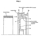
- the measuring position of the axial run-out accuracy was a position with respect to the bore portion A of the hub 2 (a bore face of a boss portion 2a) of the annular mass 3 (an end face portion of the annular mass 3), as shown in Figure 3.
- the present invention has the following effects.
- the tackiness of the silane coupling agent can be removed by applying the silane coupling agent to the faces of the hub and the annular mass between which faces the annular rubber is pressed in, and leaving the agent for drying for the predetermined time period after the application, so that the undulation of the rubber can be prevented from occurring in the pressing of the annular rubber in between the hub and the annular mass. Therefore, the strain durability of the torsional damper can be improved as desired, and a damper product having excellent durability can be provided.
Landscapes
- Engineering & Computer Science (AREA)
- General Engineering & Computer Science (AREA)
- Mechanical Engineering (AREA)
- Physics & Mathematics (AREA)
- Acoustics & Sound (AREA)
- Aviation & Aerospace Engineering (AREA)
- Pulleys (AREA)
Claims (2)
- Verfahren zum Herstellen eines Torsionsdämpfers (1), hergestellt durch Pressen eines ringförmigen Kautschuks (4) in einer axialen Richtung zwischen eine Nabe (2) und eine ringförmige Masse (3), wobei das Verfahren umfasst;
Aufbringen eines Silan-Kupplungsmittels an den Flächen (2d) (3b) der Nabe (2) und der ringförmigen Masse (3), zwischen welchen Flächen ein ringförmiger Kautschuk hineingepresst wird;
Trocknen-Lassen des Silan-Kupplungsmittels über eine bestimmte Zeitdauer nach dem Aufbringen;
Aufbringen einer geeigneten Flüssigkeit wie einem Schmieröl oder dergleichen an der Nabe (2) und einem der ringförmigen Masse (3) und dem ringförmigen Kautschuk (4) nach dem Trocknen; und
Pressen des ringförmigen Kautschuks (4) zwischen die Nabe (2) und die ringförmige Masse (3) nach dem Aufbringen. - Verfahren zum Herstellen des Torsionsdämpfers (1) nach Anspruch 1, wobei das Verfahren umfasst;
Aufbringen des Silan-Kupplungsmittels ohne Durchführen einer chemischen Oberflächenbehandlung an den Flächen (2d) (3b) der Nabe (2) und der ringförmigen Masse (3), zwischen welchen Flächen der ringförmige Kautschuk hineingepresst wird.
Applications Claiming Priority (3)
| Application Number | Priority Date | Filing Date | Title |
|---|---|---|---|
| JP2002292048A JP2004125108A (ja) | 2002-10-04 | 2002-10-04 | トーショナルダンパーの製造方法 |
| JP2002292048 | 2002-10-04 | ||
| PCT/JP2003/009337 WO2004031610A1 (ja) | 2002-10-04 | 2003-07-23 | トーショナルダンパーの製造方法 |
Publications (3)
| Publication Number | Publication Date |
|---|---|
| EP1557586A1 EP1557586A1 (de) | 2005-07-27 |
| EP1557586A4 EP1557586A4 (de) | 2005-12-14 |
| EP1557586B1 true EP1557586B1 (de) | 2006-11-02 |
Family
ID=32063909
Family Applications (1)
| Application Number | Title | Priority Date | Filing Date |
|---|---|---|---|
| EP03799070A Expired - Lifetime EP1557586B1 (de) | 2002-10-04 | 2003-07-23 | Verfahren zur herstellung von torsionsdämpfern |
Country Status (8)
| Country | Link |
|---|---|
| US (1) | US7171750B2 (de) |
| EP (1) | EP1557586B1 (de) |
| JP (1) | JP2004125108A (de) |
| KR (1) | KR20050054871A (de) |
| CN (1) | CN100334369C (de) |
| AU (1) | AU2003255150A1 (de) |
| DE (1) | DE60309500T2 (de) |
| WO (1) | WO2004031610A1 (de) |
Families Citing this family (14)
| Publication number | Priority date | Publication date | Assignee | Title |
|---|---|---|---|---|
| JP2004225829A (ja) | 2003-01-24 | 2004-08-12 | Nok Corp | トーショナルダンパの製造方法 |
| US7802492B2 (en) * | 2006-11-07 | 2010-09-28 | Metavation, Llc | Cast crankshaft damper assembly |
| CN101865274A (zh) * | 2010-06-18 | 2010-10-20 | 重庆长安汽车股份有限公司 | 一种发动机减振曲轴主动三角皮带轮 |
| US9121471B2 (en) * | 2012-05-03 | 2015-09-01 | Dayco Ip Holdings, Llc | Torsional vibration damper with nonuniform elastomer profile |
| US9506523B2 (en) * | 2014-06-12 | 2016-11-29 | Dayco Ip Holdings, Llc | Torsional vibration damper |
| CN106605080B (zh) * | 2014-09-02 | 2019-09-17 | 戴科知识产权控股有限责任公司 | 用于具有容纳一个或多个弹性体构件的盒状件的传动系统的装置 |
| EP3189246A4 (de) | 2014-09-02 | 2018-04-18 | Dayco IP Holdings, LLC | Drehschwingungsdämpfer mit zwei elastomeren elementen |
| JP6879918B2 (ja) * | 2015-01-16 | 2021-06-02 | デイコ アイピー ホールディングス, エルエルシーDayco Ip Holdings, Llc | 捩じれ振動ダンパのためのエラストマ条片設計、およびそのエラストマ条片設計を有する捩じれ振動ダンパ |
| JP6895319B2 (ja) * | 2017-06-08 | 2021-06-30 | Nok株式会社 | トーショナルダンパ |
| CN110513437A (zh) * | 2019-08-21 | 2019-11-29 | 亚新科噪声与振动技术(安徽)有限公司 | 一种多级扭转减振器 |
| JP7390871B2 (ja) * | 2019-11-20 | 2023-12-04 | Nok株式会社 | トーショナルダンパおよびその製造方法 |
| JP7638071B2 (ja) * | 2020-06-17 | 2025-03-03 | Nok株式会社 | トーショナルダンパおよびその製造方法 |
| CN112573324B (zh) * | 2020-11-26 | 2021-08-27 | 中国矿业大学 | 一种柔索自适应导向轮及其导向方法 |
| US12372148B2 (en) * | 2022-01-07 | 2025-07-29 | Nok Corporation | Torsional damper |
Family Cites Families (19)
| Publication number | Priority date | Publication date | Assignee | Title |
|---|---|---|---|---|
| US2659622A (en) * | 1950-06-10 | 1953-11-17 | Budd Co | Shock and sound absorbing vehicle wheel and the like |
| US3387839A (en) * | 1964-12-11 | 1968-06-11 | Gen Tire & Rubber Co | Adhesive bonded bushing and method of making same |
| GB2068503B (en) * | 1980-01-25 | 1983-07-06 | Concentric Pumps Ltd | Vibration dampers |
| US4378865A (en) * | 1980-12-10 | 1983-04-05 | Houdaille Industries, Inc. | Rubber and viscous/rubber torsional dampers and method of making the same |
| JPS606774A (ja) | 1983-06-27 | 1985-01-14 | Tokai Rubber Ind Ltd | ト−シヨナルダンパの製造方法 |
| JPS60139431A (ja) | 1983-12-27 | 1985-07-24 | Toyoda Gosei Co Ltd | 金属ハウジング付防振ゴムの製造方法 |
| JPS60141533A (ja) | 1983-12-28 | 1985-07-26 | Toyoda Gosei Co Ltd | 金属ハウジング付防振ゴムの製造方法 |
| US4849047A (en) * | 1986-09-29 | 1989-07-18 | Simpson Industries, Inc. | Vibration damper bonding system |
| JPH0285543A (ja) | 1988-09-20 | 1990-03-27 | Toyoda Gosei Co Ltd | ダイナミックダンパ |
| JPH01144485A (ja) * | 1988-10-04 | 1989-06-06 | Tokai Rubber Ind Ltd | トーショナルダンパ |
| JPH0357541U (de) * | 1989-07-31 | 1991-06-03 | ||
| JPH0734247B2 (ja) | 1990-09-27 | 1995-04-12 | 株式会社三協精機製作所 | かじりを防止する圧入方法 |
| JPH07198027A (ja) * | 1993-11-24 | 1995-08-01 | Toyoda Gosei Co Ltd | ダンパプーリの製造方法 |
| JPH07259961A (ja) * | 1994-03-18 | 1995-10-13 | Toyoda Gosei Co Ltd | ダンパプーリ |
| US5843264A (en) * | 1994-04-21 | 1998-12-01 | Toyoda Gosei Co., Ltd. | Vibration insulating assembly and method for making the same |
| JPH11159576A (ja) * | 1997-11-28 | 1999-06-15 | Nok Megurasutikku Kk | ダンパ |
| NL1008966C2 (nl) * | 1998-04-22 | 1999-10-25 | Skf Eng & Res Centre Bv | Spoorwegvoertuigwiel met verbeterde dempingseigenschappen. |
| JP4012358B2 (ja) | 1999-05-10 | 2007-11-21 | Nok株式会社 | トーショナルダンパ及びその製造方法 |
| JP5118792B2 (ja) | 2000-01-14 | 2013-01-16 | 株式会社フコク | ダンパおよびその製造方法 |
-
2002
- 2002-10-04 JP JP2002292048A patent/JP2004125108A/ja active Pending
-
2003
- 2003-07-23 US US10/503,495 patent/US7171750B2/en not_active Expired - Lifetime
- 2003-07-23 AU AU2003255150A patent/AU2003255150A1/en not_active Abandoned
- 2003-07-23 KR KR1020047012499A patent/KR20050054871A/ko not_active Ceased
- 2003-07-23 WO PCT/JP2003/009337 patent/WO2004031610A1/ja not_active Ceased
- 2003-07-23 CN CNB038049414A patent/CN100334369C/zh not_active Expired - Lifetime
- 2003-07-23 DE DE60309500T patent/DE60309500T2/de not_active Expired - Lifetime
- 2003-07-23 EP EP03799070A patent/EP1557586B1/de not_active Expired - Lifetime
Also Published As
| Publication number | Publication date |
|---|---|
| DE60309500D1 (de) | 2006-12-14 |
| US20050116401A1 (en) | 2005-06-02 |
| AU2003255150A1 (en) | 2004-04-23 |
| KR20050054871A (ko) | 2005-06-10 |
| WO2004031610A1 (ja) | 2004-04-15 |
| EP1557586A1 (de) | 2005-07-27 |
| CN100334369C (zh) | 2007-08-29 |
| US7171750B2 (en) | 2007-02-06 |
| EP1557586A4 (de) | 2005-12-14 |
| DE60309500T2 (de) | 2007-06-28 |
| JP2004125108A (ja) | 2004-04-22 |
| CN1639483A (zh) | 2005-07-13 |
Similar Documents
| Publication | Publication Date | Title |
|---|---|---|
| EP1557586B1 (de) | Verfahren zur herstellung von torsionsdämpfern | |
| EP1176337B1 (de) | Dämpfer und herstellungsmethode dafür | |
| US6345430B1 (en) | Damper | |
| US7150088B2 (en) | Method of manufacturing torsional damper | |
| JP7390871B2 (ja) | トーショナルダンパおよびその製造方法 | |
| EP2931581B1 (de) | Antriebswellendämpfer und montageverfahren | |
| JP2001027287A (ja) | トーショナルダンパ及びその製造方法 | |
| US20020096245A1 (en) | Method to improve adhesion between pre-cured elastomer and metal surface | |
| JP7638071B2 (ja) | トーショナルダンパおよびその製造方法 | |
| JP2000088054A (ja) | ダンパ付伝動回転体 | |
| JP2005009550A (ja) | トーショナルダンパ | |
| JPH01144485A (ja) | トーショナルダンパ | |
| JPS5936380Y2 (ja) | ダンパゴム圧入装置 | |
| JP2005009551A (ja) | トーショナルダンパ | |
| JPH0542793U (ja) | ダンパ | |
| JPH04254029A (ja) | ダンパの製造方法 | |
| CA1307934C (en) | Modular yoke end | |
| JPH0262440A (ja) | トーショナルダンパ | |
| JPH04290634A (ja) | ダンパの製造方法 |
Legal Events
| Date | Code | Title | Description |
|---|---|---|---|
| PUAI | Public reference made under article 153(3) epc to a published international application that has entered the european phase |
Free format text: ORIGINAL CODE: 0009012 |
|
| 17P | Request for examination filed |
Effective date: 20050503 |
|
| AK | Designated contracting states |
Kind code of ref document: A1 Designated state(s): AT BE BG CH CY CZ DE DK EE ES FI FR GB GR HU IE IT LI LU MC NL PT RO SE SI SK TR |
|
| AX | Request for extension of the european patent |
Extension state: AL LT LV MK |
|
| A4 | Supplementary search report drawn up and despatched |
Effective date: 20051028 |
|
| DAX | Request for extension of the european patent (deleted) | ||
| RBV | Designated contracting states (corrected) |
Designated state(s): DE FR GB |
|
| GRAP | Despatch of communication of intention to grant a patent |
Free format text: ORIGINAL CODE: EPIDOSNIGR1 |
|
| GRAS | Grant fee paid |
Free format text: ORIGINAL CODE: EPIDOSNIGR3 |
|
| GRAA | (expected) grant |
Free format text: ORIGINAL CODE: 0009210 |
|
| AK | Designated contracting states |
Kind code of ref document: B1 Designated state(s): DE FR GB |
|
| REG | Reference to a national code |
Ref country code: GB Ref legal event code: FG4D |
|
| REF | Corresponds to: |
Ref document number: 60309500 Country of ref document: DE Date of ref document: 20061214 Kind code of ref document: P |
|
| ET | Fr: translation filed | ||
| PLBE | No opposition filed within time limit |
Free format text: ORIGINAL CODE: 0009261 |
|
| STAA | Information on the status of an ep patent application or granted ep patent |
Free format text: STATUS: NO OPPOSITION FILED WITHIN TIME LIMIT |
|
| 26N | No opposition filed |
Effective date: 20070803 |
|
| REG | Reference to a national code |
Ref country code: FR Ref legal event code: PLFP Year of fee payment: 14 |
|
| REG | Reference to a national code |
Ref country code: FR Ref legal event code: PLFP Year of fee payment: 15 |
|
| REG | Reference to a national code |
Ref country code: FR Ref legal event code: PLFP Year of fee payment: 16 |
|
| PGFP | Annual fee paid to national office [announced via postgrant information from national office to epo] |
Ref country code: FR Payment date: 20200611 Year of fee payment: 18 |
|
| PGFP | Annual fee paid to national office [announced via postgrant information from national office to epo] |
Ref country code: GB Payment date: 20200716 Year of fee payment: 18 |
|
| GBPC | Gb: european patent ceased through non-payment of renewal fee |
Effective date: 20210723 |
|
| PG25 | Lapsed in a contracting state [announced via postgrant information from national office to epo] |
Ref country code: GB Free format text: LAPSE BECAUSE OF NON-PAYMENT OF DUE FEES Effective date: 20210723 |
|
| PG25 | Lapsed in a contracting state [announced via postgrant information from national office to epo] |
Ref country code: FR Free format text: LAPSE BECAUSE OF NON-PAYMENT OF DUE FEES Effective date: 20210731 |
|
| PGFP | Annual fee paid to national office [announced via postgrant information from national office to epo] |
Ref country code: DE Payment date: 20220531 Year of fee payment: 20 |
|
| REG | Reference to a national code |
Ref country code: DE Ref legal event code: R071 Ref document number: 60309500 Country of ref document: DE |