EP1580514A1 - Echangeur de chaleur destine a un dispositif a air et de congelation - Google Patents
Echangeur de chaleur destine a un dispositif a air et de congelation Download PDFInfo
- Publication number
- EP1580514A1 EP1580514A1 EP03774231A EP03774231A EP1580514A1 EP 1580514 A1 EP1580514 A1 EP 1580514A1 EP 03774231 A EP03774231 A EP 03774231A EP 03774231 A EP03774231 A EP 03774231A EP 1580514 A1 EP1580514 A1 EP 1580514A1
- Authority
- EP
- European Patent Office
- Prior art keywords
- heat exchanger
- air
- fins
- frost
- heat exchange
- Prior art date
- Legal status (The legal status is an assumption and is not a legal conclusion. Google has not performed a legal analysis and makes no representation as to the accuracy of the status listed.)
- Withdrawn
Links
- 238000005057 refrigeration Methods 0.000 claims abstract description 107
- 238000010438 heat treatment Methods 0.000 claims abstract description 98
- 239000000155 melt Substances 0.000 claims abstract description 16
- XLYOFNOQVPJJNP-UHFFFAOYSA-N water Chemical compound O XLYOFNOQVPJJNP-UHFFFAOYSA-N 0.000 claims description 353
- 229920005989 resin Polymers 0.000 claims description 80
- 239000011347 resin Substances 0.000 claims description 80
- 239000000203 mixture Substances 0.000 claims description 75
- 229920001577 copolymer Polymers 0.000 claims description 71
- OKTJSMMVPCPJKN-UHFFFAOYSA-N Carbon Chemical compound [C] OKTJSMMVPCPJKN-UHFFFAOYSA-N 0.000 claims description 66
- 239000011230 binding agent Substances 0.000 claims description 61
- 239000003507 refrigerant Substances 0.000 claims description 58
- 239000005871 repellent Substances 0.000 claims description 57
- 239000000126 substance Substances 0.000 claims description 57
- 238000004381 surface treatment Methods 0.000 claims description 57
- 229910052799 carbon Inorganic materials 0.000 claims description 56
- 239000002270 dispersing agent Substances 0.000 claims description 50
- 239000002245 particle Substances 0.000 claims description 49
- 239000000178 monomer Substances 0.000 claims description 39
- IJGRMHOSHXDMSA-UHFFFAOYSA-N Atomic nitrogen Chemical compound N#N IJGRMHOSHXDMSA-UHFFFAOYSA-N 0.000 claims description 38
- 239000004810 polytetrafluoroethylene Substances 0.000 claims description 38
- 229920001343 polytetrafluoroethylene Polymers 0.000 claims description 38
- -1 polytetrafluoroethylene Polymers 0.000 claims description 36
- 239000002904 solvent Substances 0.000 claims description 35
- 239000007789 gas Substances 0.000 claims description 30
- 229910052731 fluorine Inorganic materials 0.000 claims description 26
- 229920002554 vinyl polymer Polymers 0.000 claims description 25
- 239000011737 fluorine Substances 0.000 claims description 23
- 239000010954 inorganic particle Substances 0.000 claims description 23
- YCKRFDGAMUMZLT-UHFFFAOYSA-N Fluorine atom Chemical compound [F] YCKRFDGAMUMZLT-UHFFFAOYSA-N 0.000 claims description 20
- 229910052757 nitrogen Inorganic materials 0.000 claims description 19
- 238000001179 sorption measurement Methods 0.000 claims description 19
- 125000000391 vinyl group Chemical group [H]C([*])=C([H])[H] 0.000 claims description 18
- 229920000642 polymer Polymers 0.000 claims description 17
- 238000001816 cooling Methods 0.000 claims description 15
- 125000003709 fluoroalkyl group Chemical group 0.000 claims description 14
- 239000006229 carbon black Substances 0.000 claims description 13
- 239000003431 cross linking reagent Substances 0.000 claims description 12
- 238000007664 blowing Methods 0.000 claims description 10
- 239000012153 distilled water Substances 0.000 claims description 7
- 230000007613 environmental effect Effects 0.000 claims description 7
- 125000004435 hydrogen atom Chemical group [H]* 0.000 claims description 7
- 239000003960 organic solvent Substances 0.000 claims description 7
- 229910021393 carbon nanotube Inorganic materials 0.000 claims description 6
- 239000002041 carbon nanotube Substances 0.000 claims description 6
- 230000002441 reversible effect Effects 0.000 claims description 6
- 125000001153 fluoro group Chemical group F* 0.000 claims description 4
- 125000004209 (C1-C8) alkyl group Chemical group 0.000 claims description 3
- 229910052801 chlorine Inorganic materials 0.000 claims description 3
- 125000001309 chloro group Chemical group Cl* 0.000 claims description 3
- 125000004185 ester group Chemical group 0.000 claims description 3
- 125000002023 trifluoromethyl group Chemical group FC(F)(F)* 0.000 claims description 3
- 239000004711 α-olefin Substances 0.000 claims description 3
- 229910052796 boron Inorganic materials 0.000 abstract description 2
- 238000012360 testing method Methods 0.000 description 75
- 238000000034 method Methods 0.000 description 35
- HMBNQNDUEFFFNZ-UHFFFAOYSA-N 4-ethenoxybutan-1-ol Chemical compound OCCCCOC=C HMBNQNDUEFFFNZ-UHFFFAOYSA-N 0.000 description 34
- UUAGAQFQZIEFAH-UHFFFAOYSA-N chlorotrifluoroethylene Chemical group FC(F)=C(F)Cl UUAGAQFQZIEFAH-UHFFFAOYSA-N 0.000 description 29
- VQTUBCCKSQIDNK-UHFFFAOYSA-N Isobutene Chemical group CC(C)=C VQTUBCCKSQIDNK-UHFFFAOYSA-N 0.000 description 28
- 238000000576 coating method Methods 0.000 description 28
- 230000000694 effects Effects 0.000 description 28
- 239000011248 coating agent Substances 0.000 description 26
- BFKJFAAPBSQJPD-UHFFFAOYSA-N tetrafluoroethene Chemical group FC(F)=C(F)F BFKJFAAPBSQJPD-UHFFFAOYSA-N 0.000 description 25
- 238000010257 thawing Methods 0.000 description 22
- FJKIXWOMBXYWOQ-UHFFFAOYSA-N ethenoxyethane Chemical compound CCOC=C FJKIXWOMBXYWOQ-UHFFFAOYSA-N 0.000 description 20
- NIXOWILDQLNWCW-UHFFFAOYSA-M Acrylate Chemical compound [O-]C(=O)C=C NIXOWILDQLNWCW-UHFFFAOYSA-M 0.000 description 19
- 230000000052 comparative effect Effects 0.000 description 15
- ONIKNECPXCLUHT-UHFFFAOYSA-N 2-chlorobenzoyl chloride Chemical compound ClC(=O)C1=CC=CC=C1Cl ONIKNECPXCLUHT-UHFFFAOYSA-N 0.000 description 14
- 239000003973 paint Substances 0.000 description 14
- 238000003756 stirring Methods 0.000 description 14
- 150000001875 compounds Chemical class 0.000 description 13
- 238000002474 experimental method Methods 0.000 description 13
- 230000001976 improved effect Effects 0.000 description 12
- 230000009467 reduction Effects 0.000 description 12
- 230000009471 action Effects 0.000 description 11
- 238000002844 melting Methods 0.000 description 11
- 230000008018 melting Effects 0.000 description 11
- IMNFDUFMRHMDMM-UHFFFAOYSA-N N-Heptane Chemical compound CCCCCCC IMNFDUFMRHMDMM-UHFFFAOYSA-N 0.000 description 10
- 230000015572 biosynthetic process Effects 0.000 description 10
- LFQSCWFLJHTTHZ-UHFFFAOYSA-N Ethanol Chemical compound CCO LFQSCWFLJHTTHZ-UHFFFAOYSA-N 0.000 description 9
- UIWXSTHGICQLQT-UHFFFAOYSA-N ethenyl propanoate Chemical compound CCC(=O)OC=C UIWXSTHGICQLQT-UHFFFAOYSA-N 0.000 description 9
- 230000007246 mechanism Effects 0.000 description 9
- 229910000077 silane Inorganic materials 0.000 description 9
- LDHQCZJRKDOVOX-UHFFFAOYSA-N trans-crotonic acid Natural products CC=CC(O)=O LDHQCZJRKDOVOX-UHFFFAOYSA-N 0.000 description 9
- GCYHRYNSUGLLMA-UHFFFAOYSA-N 2-prop-2-enoxyethanol Chemical compound OCCOCC=C GCYHRYNSUGLLMA-UHFFFAOYSA-N 0.000 description 8
- QYKIQEUNHZKYBP-UHFFFAOYSA-N Vinyl ether Chemical compound C=COC=C QYKIQEUNHZKYBP-UHFFFAOYSA-N 0.000 description 8
- 229920000578 graft copolymer Polymers 0.000 description 8
- HCDGVLDPFQMKDK-UHFFFAOYSA-N hexafluoropropylene Chemical group FC(F)=C(F)C(F)(F)F HCDGVLDPFQMKDK-UHFFFAOYSA-N 0.000 description 8
- BLRPTPMANUNPDV-UHFFFAOYSA-N Silane Chemical compound [SiH4] BLRPTPMANUNPDV-UHFFFAOYSA-N 0.000 description 7
- 229910052782 aluminium Inorganic materials 0.000 description 7
- XAGFODPZIPBFFR-UHFFFAOYSA-N aluminium Chemical compound [Al] XAGFODPZIPBFFR-UHFFFAOYSA-N 0.000 description 7
- SKYXLDSRLNRAPS-UHFFFAOYSA-N 1,2,4-trifluoro-5-methoxybenzene Chemical compound COC1=CC(F)=C(F)C=C1F SKYXLDSRLNRAPS-UHFFFAOYSA-N 0.000 description 6
- DKPFZGUDAPQIHT-UHFFFAOYSA-N Butyl acetate Natural products CCCCOC(C)=O DKPFZGUDAPQIHT-UHFFFAOYSA-N 0.000 description 6
- YXFVVABEGXRONW-UHFFFAOYSA-N Toluene Chemical compound CC1=CC=CC=C1 YXFVVABEGXRONW-UHFFFAOYSA-N 0.000 description 6
- XTXRWKRVRITETP-UHFFFAOYSA-N Vinyl acetate Chemical compound CC(=O)OC=C XTXRWKRVRITETP-UHFFFAOYSA-N 0.000 description 6
- FUZZWVXGSFPDMH-UHFFFAOYSA-N hexanoic acid Chemical compound CCCCCC(O)=O FUZZWVXGSFPDMH-UHFFFAOYSA-N 0.000 description 6
- 239000000843 powder Substances 0.000 description 6
- 239000007787 solid Substances 0.000 description 6
- 229920000877 Melamine resin Polymers 0.000 description 5
- PVEOYINWKBTPIZ-UHFFFAOYSA-N but-3-enoic acid Chemical compound OC(=O)CC=C PVEOYINWKBTPIZ-UHFFFAOYSA-N 0.000 description 5
- 239000003795 chemical substances by application Substances 0.000 description 5
- 150000003972 cyclic carboxylic anhydrides Chemical class 0.000 description 5
- 239000006185 dispersion Substances 0.000 description 5
- 230000008020 evaporation Effects 0.000 description 5
- 238000001704 evaporation Methods 0.000 description 5
- 230000008014 freezing Effects 0.000 description 5
- 238000007710 freezing Methods 0.000 description 5
- 125000002887 hydroxy group Chemical group [H]O* 0.000 description 5
- 238000002156 mixing Methods 0.000 description 5
- 230000000717 retained effect Effects 0.000 description 5
- 238000005507 spraying Methods 0.000 description 5
- KOZCZZVUFDCZGG-UHFFFAOYSA-N vinyl benzoate Chemical compound C=COC(=O)C1=CC=CC=C1 KOZCZZVUFDCZGG-UHFFFAOYSA-N 0.000 description 5
- NIXOWILDQLNWCW-UHFFFAOYSA-N Acrylic acid Chemical compound OC(=O)C=C NIXOWILDQLNWCW-UHFFFAOYSA-N 0.000 description 4
- LYCAIKOWRPUZTN-UHFFFAOYSA-N Ethylene glycol Chemical compound OCCO LYCAIKOWRPUZTN-UHFFFAOYSA-N 0.000 description 4
- LRHPLDYGYMQRHN-UHFFFAOYSA-N N-Butanol Chemical compound CCCCO LRHPLDYGYMQRHN-UHFFFAOYSA-N 0.000 description 4
- 150000001252 acrylic acid derivatives Chemical class 0.000 description 4
- 239000012948 isocyanate Substances 0.000 description 4
- 239000007788 liquid Substances 0.000 description 4
- VLKZOEOYAKHREP-UHFFFAOYSA-N n-Hexane Chemical compound CCCCCC VLKZOEOYAKHREP-UHFFFAOYSA-N 0.000 description 4
- 239000003495 polar organic solvent Substances 0.000 description 4
- 239000000047 product Substances 0.000 description 4
- 229920002050 silicone resin Polymers 0.000 description 4
- 238000005406 washing Methods 0.000 description 4
- OZCMOJQQLBXBKI-UHFFFAOYSA-N 1-ethenoxy-2-methylpropane Chemical compound CC(C)COC=C OZCMOJQQLBXBKI-UHFFFAOYSA-N 0.000 description 3
- ATVJXMYDOSMEPO-UHFFFAOYSA-N 3-prop-2-enoxyprop-1-ene Chemical compound C=CCOCC=C ATVJXMYDOSMEPO-UHFFFAOYSA-N 0.000 description 3
- CSCPPACGZOOCGX-UHFFFAOYSA-N Acetone Chemical compound CC(C)=O CSCPPACGZOOCGX-UHFFFAOYSA-N 0.000 description 3
- HRPVXLWXLXDGHG-UHFFFAOYSA-N Acrylamide Chemical compound NC(=O)C=C HRPVXLWXLXDGHG-UHFFFAOYSA-N 0.000 description 3
- VGGSQFUCUMXWEO-UHFFFAOYSA-N Ethene Chemical compound C=C VGGSQFUCUMXWEO-UHFFFAOYSA-N 0.000 description 3
- XEKOWRVHYACXOJ-UHFFFAOYSA-N Ethyl acetate Chemical compound CCOC(C)=O XEKOWRVHYACXOJ-UHFFFAOYSA-N 0.000 description 3
- 239000005977 Ethylene Substances 0.000 description 3
- 239000004640 Melamine resin Substances 0.000 description 3
- CERQOIWHTDAKMF-UHFFFAOYSA-N Methacrylic acid Chemical compound CC(=C)C(O)=O CERQOIWHTDAKMF-UHFFFAOYSA-N 0.000 description 3
- OKKJLVBELUTLKV-UHFFFAOYSA-N Methanol Chemical compound OC OKKJLVBELUTLKV-UHFFFAOYSA-N 0.000 description 3
- 229910019142 PO4 Inorganic materials 0.000 description 3
- 150000008065 acid anhydrides Chemical class 0.000 description 3
- 125000003647 acryloyl group Chemical group O=C([*])C([H])=C([H])[H] 0.000 description 3
- 125000002947 alkylene group Chemical group 0.000 description 3
- 125000003178 carboxy group Chemical group [H]OC(*)=O 0.000 description 3
- LDHQCZJRKDOVOX-NSCUHMNNSA-N crotonic acid Chemical compound C\C=C\C(O)=O LDHQCZJRKDOVOX-NSCUHMNNSA-N 0.000 description 3
- 239000013078 crystal Substances 0.000 description 3
- IQPQWNKOIGAROB-UHFFFAOYSA-N isocyanate group Chemical group [N-]=C=O IQPQWNKOIGAROB-UHFFFAOYSA-N 0.000 description 3
- 239000000463 material Substances 0.000 description 3
- 229910021382 natural graphite Inorganic materials 0.000 description 3
- 239000003208 petroleum Substances 0.000 description 3
- NBIIXXVUZAFLBC-UHFFFAOYSA-K phosphate Chemical compound [O-]P([O-])([O-])=O NBIIXXVUZAFLBC-UHFFFAOYSA-K 0.000 description 3
- 239000010452 phosphate Substances 0.000 description 3
- 125000004805 propylene group Chemical group [H]C([H])([H])C([H])([*:1])C([H])([H])[*:2] 0.000 description 3
- 229920002545 silicone oil Polymers 0.000 description 3
- 238000009423 ventilation Methods 0.000 description 3
- 125000000008 (C1-C10) alkyl group Chemical group 0.000 description 2
- FKTXDTWDCPTPHK-UHFFFAOYSA-N 1,1,1,2,3,3,3-heptafluoropropane Chemical compound FC(F)(F)[C](F)C(F)(F)F FKTXDTWDCPTPHK-UHFFFAOYSA-N 0.000 description 2
- WWUVJRULCWHUSA-UHFFFAOYSA-N 2-methyl-1-pentene Chemical compound CCCC(C)=C WWUVJRULCWHUSA-UHFFFAOYSA-N 0.000 description 2
- KAKZBPTYRLMSJV-UHFFFAOYSA-N Butadiene Chemical compound C=CC=C KAKZBPTYRLMSJV-UHFFFAOYSA-N 0.000 description 2
- RYGMFSIKBFXOCR-UHFFFAOYSA-N Copper Chemical compound [Cu] RYGMFSIKBFXOCR-UHFFFAOYSA-N 0.000 description 2
- XDTMQSROBMDMFD-UHFFFAOYSA-N Cyclohexane Chemical compound C1CCCCC1 XDTMQSROBMDMFD-UHFFFAOYSA-N 0.000 description 2
- SJIXRGNQPBQWMK-UHFFFAOYSA-N DEAEMA Natural products CCN(CC)CCOC(=O)C(C)=C SJIXRGNQPBQWMK-UHFFFAOYSA-N 0.000 description 2
- XEEYBQQBJWHFJM-UHFFFAOYSA-N Iron Chemical compound [Fe] XEEYBQQBJWHFJM-UHFFFAOYSA-N 0.000 description 2
- KFZMGEQAYNKOFK-UHFFFAOYSA-N Isopropanol Chemical compound CC(C)O KFZMGEQAYNKOFK-UHFFFAOYSA-N 0.000 description 2
- CTQNGGLPUBDAKN-UHFFFAOYSA-N O-Xylene Chemical compound CC1=CC=CC=C1C CTQNGGLPUBDAKN-UHFFFAOYSA-N 0.000 description 2
- XUIMIQQOPSSXEZ-UHFFFAOYSA-N Silicon Chemical compound [Si] XUIMIQQOPSSXEZ-UHFFFAOYSA-N 0.000 description 2
- PPBRXRYQALVLMV-UHFFFAOYSA-N Styrene Chemical compound C=CC1=CC=CC=C1 PPBRXRYQALVLMV-UHFFFAOYSA-N 0.000 description 2
- 241000779819 Syncarpia glomulifera Species 0.000 description 2
- WYURNTSHIVDZCO-UHFFFAOYSA-N Tetrahydrofuran Chemical compound C1CCOC1 WYURNTSHIVDZCO-UHFFFAOYSA-N 0.000 description 2
- 239000007983 Tris buffer Substances 0.000 description 2
- 239000002253 acid Substances 0.000 description 2
- 230000002378 acidificating effect Effects 0.000 description 2
- 239000000654 additive Substances 0.000 description 2
- 150000001336 alkenes Chemical class 0.000 description 2
- 125000000217 alkyl group Chemical group 0.000 description 2
- XXROGKLTLUQVRX-UHFFFAOYSA-N allyl alcohol Chemical compound OCC=C XXROGKLTLUQVRX-UHFFFAOYSA-N 0.000 description 2
- 229920003180 amino resin Polymers 0.000 description 2
- 230000008859 change Effects 0.000 description 2
- 239000000470 constituent Substances 0.000 description 2
- 229910052802 copper Inorganic materials 0.000 description 2
- 239000010949 copper Substances 0.000 description 2
- 230000007423 decrease Effects 0.000 description 2
- 230000003111 delayed effect Effects 0.000 description 2
- 238000013461 design Methods 0.000 description 2
- 238000011161 development Methods 0.000 description 2
- JBSLOWBPDRZSMB-BQYQJAHWSA-N dibutyl (e)-but-2-enedioate Chemical compound CCCCOC(=O)\C=C\C(=O)OCCCC JBSLOWBPDRZSMB-BQYQJAHWSA-N 0.000 description 2
- JBSLOWBPDRZSMB-FPLPWBNLSA-N dibutyl (z)-but-2-enedioate Chemical compound CCCCOC(=O)\C=C/C(=O)OCCCC JBSLOWBPDRZSMB-FPLPWBNLSA-N 0.000 description 2
- IEPRKVQEAMIZSS-AATRIKPKSA-N diethyl fumarate Chemical compound CCOC(=O)\C=C\C(=O)OCC IEPRKVQEAMIZSS-AATRIKPKSA-N 0.000 description 2
- 125000003700 epoxy group Chemical group 0.000 description 2
- 125000002768 hydroxyalkyl group Chemical group 0.000 description 2
- 150000002513 isocyanates Chemical class 0.000 description 2
- FPYJFEHAWHCUMM-UHFFFAOYSA-N maleic anhydride Chemical compound O=C1OC(=O)C=C1 FPYJFEHAWHCUMM-UHFFFAOYSA-N 0.000 description 2
- 238000005259 measurement Methods 0.000 description 2
- JDSHMPZPIAZGSV-UHFFFAOYSA-N melamine Chemical compound NC1=NC(N)=NC(N)=N1 JDSHMPZPIAZGSV-UHFFFAOYSA-N 0.000 description 2
- 229910052751 metal Inorganic materials 0.000 description 2
- 239000002184 metal Substances 0.000 description 2
- 125000002496 methyl group Chemical group [H]C([H])([H])* 0.000 description 2
- UAEPNZWRGJTJPN-UHFFFAOYSA-N methylcyclohexane Chemical compound CC1CCCCC1 UAEPNZWRGJTJPN-UHFFFAOYSA-N 0.000 description 2
- DNIAPMSPPWPWGF-UHFFFAOYSA-N monopropylene glycol Natural products CC(O)CO DNIAPMSPPWPWGF-UHFFFAOYSA-N 0.000 description 2
- 239000002116 nanohorn Substances 0.000 description 2
- 229910052755 nonmetal Inorganic materials 0.000 description 2
- 239000001739 pinus spp. Substances 0.000 description 2
- 229950010765 pivalate Drugs 0.000 description 2
- 229920000548 poly(silane) polymer Polymers 0.000 description 2
- 229920001225 polyester resin Polymers 0.000 description 2
- 239000004645 polyester resin Substances 0.000 description 2
- 229920001296 polysiloxane Polymers 0.000 description 2
- 239000011164 primary particle Substances 0.000 description 2
- 238000012545 processing Methods 0.000 description 2
- QQONPFPTGQHPMA-UHFFFAOYSA-N propylene Natural products CC=C QQONPFPTGQHPMA-UHFFFAOYSA-N 0.000 description 2
- 230000002940 repellent Effects 0.000 description 2
- 229910052710 silicon Inorganic materials 0.000 description 2
- 125000003808 silyl group Chemical group [H][Si]([H])([H])[*] 0.000 description 2
- 229940036248 turpentine Drugs 0.000 description 2
- 229920001567 vinyl ester resin Polymers 0.000 description 2
- 239000008096 xylene Substances 0.000 description 2
- PRBBFHSSJFGXJS-UHFFFAOYSA-N (2,2-dimethyl-3-prop-2-enoyloxypropyl) prop-2-enoate;3-hydroxy-2,2-dimethylpropanoic acid Chemical compound OCC(C)(C)C(O)=O.C=CC(=O)OCC(C)(C)COC(=O)C=C PRBBFHSSJFGXJS-UHFFFAOYSA-N 0.000 description 1
- HHQAGBQXOWLTLL-UHFFFAOYSA-N (2-hydroxy-3-phenoxypropyl) prop-2-enoate Chemical compound C=CC(=O)OCC(O)COC1=CC=CC=C1 HHQAGBQXOWLTLL-UHFFFAOYSA-N 0.000 description 1
- ZODNDDPVCIAZIQ-UHFFFAOYSA-N (2-hydroxy-3-prop-2-enoyloxypropyl) 2-methylprop-2-enoate Chemical compound CC(=C)C(=O)OCC(O)COC(=O)C=C ZODNDDPVCIAZIQ-UHFFFAOYSA-N 0.000 description 1
- 125000006832 (C1-C10) alkylene group Chemical group 0.000 description 1
- DNIAPMSPPWPWGF-GSVOUGTGSA-N (R)-(-)-Propylene glycol Chemical compound C[C@@H](O)CO DNIAPMSPPWPWGF-GSVOUGTGSA-N 0.000 description 1
- FKTHNVSLHLHISI-UHFFFAOYSA-N 1,2-bis(isocyanatomethyl)benzene Chemical compound O=C=NCC1=CC=CC=C1CN=C=O FKTHNVSLHLHISI-UHFFFAOYSA-N 0.000 description 1
- 125000001140 1,4-phenylene group Chemical group [H]C1=C([H])C([*:2])=C([H])C([H])=C1[*:1] 0.000 description 1
- VZXPHDGHQXLXJC-UHFFFAOYSA-N 1,6-diisocyanato-5,6-dimethylheptane Chemical compound O=C=NC(C)(C)C(C)CCCCN=C=O VZXPHDGHQXLXJC-UHFFFAOYSA-N 0.000 description 1
- DZSVIVLGBJKQAP-UHFFFAOYSA-N 1-(2-methyl-5-propan-2-ylcyclohex-2-en-1-yl)propan-1-one Chemical compound CCC(=O)C1CC(C(C)C)CC=C1C DZSVIVLGBJKQAP-UHFFFAOYSA-N 0.000 description 1
- NQUXRXBRYDZZDL-UHFFFAOYSA-N 1-(2-prop-2-enoyloxyethyl)cyclohexane-1,2-dicarboxylic acid Chemical compound OC(=O)C1CCCCC1(CCOC(=O)C=C)C(O)=O NQUXRXBRYDZZDL-UHFFFAOYSA-N 0.000 description 1
- QQHQTCGEZWTSEJ-UHFFFAOYSA-N 1-ethenyl-4-propan-2-ylbenzene Chemical compound CC(C)C1=CC=C(C=C)C=C1 QQHQTCGEZWTSEJ-UHFFFAOYSA-N 0.000 description 1
- QRIMLDXJAPZHJE-UHFFFAOYSA-N 2,3-dihydroxypropyl 2-methylprop-2-enoate Chemical compound CC(=C)C(=O)OCC(O)CO QRIMLDXJAPZHJE-UHFFFAOYSA-N 0.000 description 1
- SMZOUWXMTYCWNB-UHFFFAOYSA-N 2-(2-methoxy-5-methylphenyl)ethanamine Chemical compound COC1=CC=C(C)C=C1CCN SMZOUWXMTYCWNB-UHFFFAOYSA-N 0.000 description 1
- DIOZVWSHACHNRT-UHFFFAOYSA-N 2-(2-prop-2-enoxyethoxy)ethanol Chemical compound OCCOCCOCC=C DIOZVWSHACHNRT-UHFFFAOYSA-N 0.000 description 1
- JAHNSTQSQJOJLO-UHFFFAOYSA-N 2-(3-fluorophenyl)-1h-imidazole Chemical compound FC1=CC=CC(C=2NC=CN=2)=C1 JAHNSTQSQJOJLO-UHFFFAOYSA-N 0.000 description 1
- JKNCOURZONDCGV-UHFFFAOYSA-N 2-(dimethylamino)ethyl 2-methylprop-2-enoate Chemical compound CN(C)CCOC(=O)C(C)=C JKNCOURZONDCGV-UHFFFAOYSA-N 0.000 description 1
- FIQBJLHOPOSODG-UHFFFAOYSA-N 2-[2-(2-methylprop-2-enoyloxy)ethoxycarbonyl]benzoic acid Chemical compound CC(=C)C(=O)OCCOC(=O)C1=CC=CC=C1C(O)=O FIQBJLHOPOSODG-UHFFFAOYSA-N 0.000 description 1
- ARMWSTGKHHACOF-UHFFFAOYSA-N 2-ethenoxyethyl(triethoxy)silane Chemical compound CCO[Si](OCC)(OCC)CCOC=C ARMWSTGKHHACOF-UHFFFAOYSA-N 0.000 description 1
- TYZRVQDBDAPABU-UHFFFAOYSA-N 2-ethenoxyethyl(trimethoxy)silane Chemical compound CO[Si](OC)(OC)CCOC=C TYZRVQDBDAPABU-UHFFFAOYSA-N 0.000 description 1
- OMIGHNLMNHATMP-UHFFFAOYSA-N 2-hydroxyethyl prop-2-enoate Chemical compound OCCOC(=O)C=C OMIGHNLMNHATMP-UHFFFAOYSA-N 0.000 description 1
- SEILKFZTLVMHRR-UHFFFAOYSA-N 2-phosphonooxyethyl 2-methylprop-2-enoate Chemical compound CC(=C)C(=O)OCCOP(O)(O)=O SEILKFZTLVMHRR-UHFFFAOYSA-N 0.000 description 1
- QISZCVLALJOROC-UHFFFAOYSA-N 3-(2-hydroxyethyl)-4-(2-prop-2-enoyloxyethyl)phthalic acid Chemical compound OCCC1=C(CCOC(=O)C=C)C=CC(C(O)=O)=C1C(O)=O QISZCVLALJOROC-UHFFFAOYSA-N 0.000 description 1
- UXTGJIIBLZIQPK-UHFFFAOYSA-N 3-(2-prop-2-enoyloxyethyl)phthalic acid Chemical compound OC(=O)C1=CC=CC(CCOC(=O)C=C)=C1C(O)=O UXTGJIIBLZIQPK-UHFFFAOYSA-N 0.000 description 1
- VLDQEHUZQHHLHD-UHFFFAOYSA-N 3-ethenoxypropyl(triethoxy)silane Chemical compound CCO[Si](OCC)(OCC)CCCOC=C VLDQEHUZQHHLHD-UHFFFAOYSA-N 0.000 description 1
- JMICBDHJGYAFMU-UHFFFAOYSA-N 3-ethenoxypropyl(trimethoxy)silane Chemical compound CO[Si](OC)(OC)CCCOC=C JMICBDHJGYAFMU-UHFFFAOYSA-N 0.000 description 1
- GNSFRPWPOGYVLO-UHFFFAOYSA-N 3-hydroxypropyl 2-methylprop-2-enoate Chemical compound CC(=C)C(=O)OCCCO GNSFRPWPOGYVLO-UHFFFAOYSA-N 0.000 description 1
- AUWAZZUJAGXIDZ-UHFFFAOYSA-M 3-hydroxypropyl(trimethyl)azanium;2-methylprop-2-enoic acid;chloride Chemical compound [Cl-].CC(=C)C(O)=O.C[N+](C)(C)CCCO AUWAZZUJAGXIDZ-UHFFFAOYSA-M 0.000 description 1
- AYKYXWQEBUNJCN-UHFFFAOYSA-N 3-methylfuran-2,5-dione Chemical compound CC1=CC(=O)OC1=O AYKYXWQEBUNJCN-UHFFFAOYSA-N 0.000 description 1
- OFNISBHGPNMTMS-UHFFFAOYSA-N 3-methylideneoxolane-2,5-dione Chemical compound C=C1CC(=O)OC1=O OFNISBHGPNMTMS-UHFFFAOYSA-N 0.000 description 1
- UPMLOUAZCHDJJD-UHFFFAOYSA-N 4,4'-Diphenylmethane Diisocyanate Chemical compound C1=CC(N=C=O)=CC=C1CC1=CC=C(N=C=O)C=C1 UPMLOUAZCHDJJD-UHFFFAOYSA-N 0.000 description 1
- IEJGRVMVZRCTDO-UHFFFAOYSA-N 4-ethenoxybutyl(triethoxy)silane Chemical compound CCO[Si](OCC)(OCC)CCCCOC=C IEJGRVMVZRCTDO-UHFFFAOYSA-N 0.000 description 1
- FOMOXQMBTDHQPO-UHFFFAOYSA-N 4-ethenoxybutyl(trimethoxy)silane Chemical compound CO[Si](OC)(OC)CCCCOC=C FOMOXQMBTDHQPO-UHFFFAOYSA-N 0.000 description 1
- UZDMJPAQQFSMMV-UHFFFAOYSA-N 4-oxo-4-(2-prop-2-enoyloxyethoxy)butanoic acid Chemical compound OC(=O)CCC(=O)OCCOC(=O)C=C UZDMJPAQQFSMMV-UHFFFAOYSA-N 0.000 description 1
- MWSKJDNQKGCKPA-UHFFFAOYSA-N 6-methyl-3a,4,5,7a-tetrahydro-2-benzofuran-1,3-dione Chemical compound C1CC(C)=CC2C(=O)OC(=O)C12 MWSKJDNQKGCKPA-UHFFFAOYSA-N 0.000 description 1
- GZVHEAJQGPRDLQ-UHFFFAOYSA-N 6-phenyl-1,3,5-triazine-2,4-diamine Chemical compound NC1=NC(N)=NC(C=2C=CC=CC=2)=N1 GZVHEAJQGPRDLQ-UHFFFAOYSA-N 0.000 description 1
- KNDQHSIWLOJIGP-UHFFFAOYSA-N 826-62-0 Chemical compound C1C2C3C(=O)OC(=O)C3C1C=C2 KNDQHSIWLOJIGP-UHFFFAOYSA-N 0.000 description 1
- 229920000178 Acrylic resin Polymers 0.000 description 1
- 239000004925 Acrylic resin Substances 0.000 description 1
- NLHHRLWOUZZQLW-UHFFFAOYSA-N Acrylonitrile Chemical compound C=CC#N NLHHRLWOUZZQLW-UHFFFAOYSA-N 0.000 description 1
- ZOXJGFHDIHLPTG-UHFFFAOYSA-N Boron Chemical compound [B] ZOXJGFHDIHLPTG-UHFFFAOYSA-N 0.000 description 1
- XMWRBQBLMFGWIX-UHFFFAOYSA-N C60 fullerene Chemical compound C12=C3C(C4=C56)=C7C8=C5C5=C9C%10=C6C6=C4C1=C1C4=C6C6=C%10C%10=C9C9=C%11C5=C8C5=C8C7=C3C3=C7C2=C1C1=C2C4=C6C4=C%10C6=C9C9=C%11C5=C5C8=C3C3=C7C1=C1C2=C4C6=C2C9=C5C3=C12 XMWRBQBLMFGWIX-UHFFFAOYSA-N 0.000 description 1
- ULPDSNLBZMHGPI-UHFFFAOYSA-N CC1CC2OC2CC1 Chemical compound CC1CC2OC2CC1 ULPDSNLBZMHGPI-UHFFFAOYSA-N 0.000 description 1
- IEPRKVQEAMIZSS-UHFFFAOYSA-N Di-Et ester-Fumaric acid Natural products CCOC(=O)C=CC(=O)OCC IEPRKVQEAMIZSS-UHFFFAOYSA-N 0.000 description 1
- 241000280258 Dyschoriste linearis Species 0.000 description 1
- 239000004593 Epoxy Substances 0.000 description 1
- 239000005057 Hexamethylene diisocyanate Substances 0.000 description 1
- 239000005058 Isophorone diisocyanate Substances 0.000 description 1
- CERQOIWHTDAKMF-UHFFFAOYSA-M Methacrylate Chemical compound CC(=C)C([O-])=O CERQOIWHTDAKMF-UHFFFAOYSA-M 0.000 description 1
- NTIZESTWPVYFNL-UHFFFAOYSA-N Methyl isobutyl ketone Chemical compound CC(C)CC(C)=O NTIZESTWPVYFNL-UHFFFAOYSA-N 0.000 description 1
- UIHCLUNTQKBZGK-UHFFFAOYSA-N Methyl isobutyl ketone Natural products CCC(C)C(C)=O UIHCLUNTQKBZGK-UHFFFAOYSA-N 0.000 description 1
- WHNWPMSKXPGLAX-UHFFFAOYSA-N N-Vinyl-2-pyrrolidone Chemical compound C=CN1CCCC1=O WHNWPMSKXPGLAX-UHFFFAOYSA-N 0.000 description 1
- LGRFSURHDFAFJT-UHFFFAOYSA-N Phthalic anhydride Natural products C1=CC=C2C(=O)OC(=O)C2=C1 LGRFSURHDFAFJT-UHFFFAOYSA-N 0.000 description 1
- OFOBLEOULBTSOW-UHFFFAOYSA-N Propanedioic acid Natural products OC(=O)CC(O)=O OFOBLEOULBTSOW-UHFFFAOYSA-N 0.000 description 1
- 229910020175 SiOH Chemical group 0.000 description 1
- BQCADISMDOOEFD-UHFFFAOYSA-N Silver Chemical compound [Ag] BQCADISMDOOEFD-UHFFFAOYSA-N 0.000 description 1
- BOTDANWDWHJENH-UHFFFAOYSA-N Tetraethyl orthosilicate Chemical compound CCO[Si](OCC)(OCC)OCC BOTDANWDWHJENH-UHFFFAOYSA-N 0.000 description 1
- 229920001807 Urea-formaldehyde Polymers 0.000 description 1
- BZHJMEDXRYGGRV-UHFFFAOYSA-N Vinyl chloride Chemical compound ClC=C BZHJMEDXRYGGRV-UHFFFAOYSA-N 0.000 description 1
- KNZPDNOSIRNYEG-UHFFFAOYSA-N [diacetyloxy(hexyl)silyl] acetate Chemical compound CCCCCC[Si](OC(C)=O)(OC(C)=O)OC(C)=O KNZPDNOSIRNYEG-UHFFFAOYSA-N 0.000 description 1
- FVVIMRCUCPNGPB-UHFFFAOYSA-N [pentanoyloxy-di(propan-2-yloxy)silyl] pentanoate Chemical compound CCCCC(=O)O[Si](OC(C)C)(OC(C)C)OC(=O)CCCC FVVIMRCUCPNGPB-UHFFFAOYSA-N 0.000 description 1
- 239000006096 absorbing agent Substances 0.000 description 1
- 239000006230 acetylene black Substances 0.000 description 1
- 150000007513 acids Chemical class 0.000 description 1
- 150000003926 acrylamides Chemical class 0.000 description 1
- 230000000996 additive effect Effects 0.000 description 1
- 150000001343 alkyl silanes Chemical class 0.000 description 1
- 239000000956 alloy Substances 0.000 description 1
- 229910045601 alloy Inorganic materials 0.000 description 1
- 150000008064 anhydrides Chemical class 0.000 description 1
- 239000003963 antioxidant agent Substances 0.000 description 1
- 230000003078 antioxidant effect Effects 0.000 description 1
- 125000000732 arylene group Chemical group 0.000 description 1
- 125000001797 benzyl group Chemical group [H]C1=C([H])C([H])=C(C([H])=C1[H])C([H])([H])* 0.000 description 1
- JHIWVOJDXOSYLW-UHFFFAOYSA-N butyl 2,2-difluorocyclopropane-1-carboxylate Chemical compound CCCCOC(=O)C1CC1(F)F JHIWVOJDXOSYLW-UHFFFAOYSA-N 0.000 description 1
- 239000011203 carbon fibre reinforced carbon Substances 0.000 description 1
- 239000000919 ceramic Substances 0.000 description 1
- 239000006231 channel black Substances 0.000 description 1
- 239000007795 chemical reaction product Substances 0.000 description 1
- YACLQRRMGMJLJV-UHFFFAOYSA-N chloroprene Chemical compound ClC(=C)C=C YACLQRRMGMJLJV-UHFFFAOYSA-N 0.000 description 1
- 238000007796 conventional method Methods 0.000 description 1
- 230000007797 corrosion Effects 0.000 description 1
- 238000005260 corrosion Methods 0.000 description 1
- 238000004132 cross linking Methods 0.000 description 1
- 125000000113 cyclohexyl group Chemical group [H]C1([H])C([H])([H])C([H])([H])C([H])(*)C([H])([H])C1([H])[H] 0.000 description 1
- LLBLHAHQBJSHED-UHFFFAOYSA-N di(propan-2-yl)-dipropoxysilane Chemical compound CCCO[Si](C(C)C)(C(C)C)OCCC LLBLHAHQBJSHED-UHFFFAOYSA-N 0.000 description 1
- SWXVUIWOUIDPGS-UHFFFAOYSA-N diacetone alcohol Chemical compound CC(=O)CC(C)(C)O SWXVUIWOUIDPGS-UHFFFAOYSA-N 0.000 description 1
- OSMIWEAIYFILPL-UHFFFAOYSA-N dibutoxy(diphenyl)silane Chemical compound C=1C=CC=CC=1[Si](OCCCC)(OCCCC)C1=CC=CC=C1 OSMIWEAIYFILPL-UHFFFAOYSA-N 0.000 description 1
- YPENMAABQGWRBR-UHFFFAOYSA-N dibutyl(dimethoxy)silane Chemical compound CCCC[Si](OC)(OC)CCCC YPENMAABQGWRBR-UHFFFAOYSA-N 0.000 description 1
- 235000014113 dietary fatty acids Nutrition 0.000 description 1
- CPKTUMHHHOVSQC-UHFFFAOYSA-N diethyl-hydroxy-silylsilane Chemical compound CC[Si](O)([SiH3])CC CPKTUMHHHOVSQC-UHFFFAOYSA-N 0.000 description 1
- JJQZDUKDJDQPMQ-UHFFFAOYSA-N dimethoxy(dimethyl)silane Chemical compound CO[Si](C)(C)OC JJQZDUKDJDQPMQ-UHFFFAOYSA-N 0.000 description 1
- 238000003618 dip coating Methods 0.000 description 1
- SHEYKHMHFCPWCL-UHFFFAOYSA-N disilanyl-hydroxy-methylsilane Chemical compound C[SiH](O)[SiH2][SiH3] SHEYKHMHFCPWCL-UHFFFAOYSA-N 0.000 description 1
- SXWUUUJQQVXKKY-UHFFFAOYSA-N disilanyl-hydroxy-phenylsilane Chemical compound [SiH3][SiH2][SiH](O)C1=CC=CC=C1 SXWUUUJQQVXKKY-UHFFFAOYSA-N 0.000 description 1
- 125000003438 dodecyl group Chemical group [H]C([H])([H])C([H])([H])C([H])([H])C([H])([H])C([H])([H])C([H])([H])C([H])([H])C([H])([H])C([H])([H])C([H])([H])C([H])([H])C([H])([H])* 0.000 description 1
- 150000002148 esters Chemical class 0.000 description 1
- XPSQBNPZMNWIPV-UHFFFAOYSA-N ethenoxyperoxyethene Chemical compound C=COOOC=C XPSQBNPZMNWIPV-UHFFFAOYSA-N 0.000 description 1
- YCUBDDIKWLELPD-UHFFFAOYSA-N ethenyl 2,2-dimethylpropanoate Chemical compound CC(C)(C)C(=O)OC=C YCUBDDIKWLELPD-UHFFFAOYSA-N 0.000 description 1
- FWDBOZPQNFPOLF-UHFFFAOYSA-N ethenyl(triethoxy)silane Chemical compound CCO[Si](OCC)(OCC)C=C FWDBOZPQNFPOLF-UHFFFAOYSA-N 0.000 description 1
- NKSJNEHGWDZZQF-UHFFFAOYSA-N ethenyl(trimethoxy)silane Chemical compound CO[Si](OC)(OC)C=C NKSJNEHGWDZZQF-UHFFFAOYSA-N 0.000 description 1
- NNBRCHPBPDRPIT-UHFFFAOYSA-N ethenyl(tripropoxy)silane Chemical compound CCCO[Si](OCCC)(OCCC)C=C NNBRCHPBPDRPIT-UHFFFAOYSA-N 0.000 description 1
- MBGQQKKTDDNCSG-UHFFFAOYSA-N ethenyl-diethoxy-methylsilane Chemical compound CCO[Si](C)(C=C)OCC MBGQQKKTDDNCSG-UHFFFAOYSA-N 0.000 description 1
- ZLNAFSPCNATQPQ-UHFFFAOYSA-N ethenyl-dimethoxy-methylsilane Chemical compound CO[Si](C)(OC)C=C ZLNAFSPCNATQPQ-UHFFFAOYSA-N 0.000 description 1
- NUFVQEIPPHHQCK-UHFFFAOYSA-N ethenyl-methoxy-dimethylsilane Chemical compound CO[Si](C)(C)C=C NUFVQEIPPHHQCK-UHFFFAOYSA-N 0.000 description 1
- GBFVZTUQONJGSL-UHFFFAOYSA-N ethenyl-tris(prop-1-en-2-yloxy)silane Chemical compound CC(=C)O[Si](OC(C)=C)(OC(C)=C)C=C GBFVZTUQONJGSL-UHFFFAOYSA-N 0.000 description 1
- 125000005670 ethenylalkyl group Chemical group 0.000 description 1
- RTZKZFJDLAIYFH-UHFFFAOYSA-N ether Substances CCOCC RTZKZFJDLAIYFH-UHFFFAOYSA-N 0.000 description 1
- FJKCDSVHCNEOOS-UHFFFAOYSA-N ethoxy(diphenyl)silane Chemical compound C=1C=CC=CC=1[SiH](OCC)C1=CC=CC=C1 FJKCDSVHCNEOOS-UHFFFAOYSA-N 0.000 description 1
- 230000001747 exhibiting effect Effects 0.000 description 1
- 229930195729 fatty acid Natural products 0.000 description 1
- 239000000194 fatty acid Substances 0.000 description 1
- 150000004665 fatty acids Chemical class 0.000 description 1
- NBVXSUQYWXRMNV-UHFFFAOYSA-N fluoromethane Chemical compound FC NBVXSUQYWXRMNV-UHFFFAOYSA-N 0.000 description 1
- 229910003472 fullerene Inorganic materials 0.000 description 1
- 239000006232 furnace black Substances 0.000 description 1
- ANSXAPJVJOKRDJ-UHFFFAOYSA-N furo[3,4-f][2]benzofuran-1,3,5,7-tetrone Chemical compound C1=C2C(=O)OC(=O)C2=CC2=C1C(=O)OC2=O ANSXAPJVJOKRDJ-UHFFFAOYSA-N 0.000 description 1
- 125000003055 glycidyl group Chemical group C(C1CO1)* 0.000 description 1
- VOZRXNHHFUQHIL-UHFFFAOYSA-N glycidyl methacrylate Chemical compound CC(=C)C(=O)OCC1CO1 VOZRXNHHFUQHIL-UHFFFAOYSA-N 0.000 description 1
- VPVSTMAPERLKKM-UHFFFAOYSA-N glycoluril Chemical compound N1C(=O)NC2NC(=O)NC21 VPVSTMAPERLKKM-UHFFFAOYSA-N 0.000 description 1
- PCHJSUWPFVWCPO-UHFFFAOYSA-N gold Chemical compound [Au] PCHJSUWPFVWCPO-UHFFFAOYSA-N 0.000 description 1
- 229910052737 gold Inorganic materials 0.000 description 1
- 239000010931 gold Substances 0.000 description 1
- FLBJFXNAEMSXGL-UHFFFAOYSA-N het anhydride Chemical compound O=C1OC(=O)C2C1C1(Cl)C(Cl)=C(Cl)C2(Cl)C1(Cl)Cl FLBJFXNAEMSXGL-UHFFFAOYSA-N 0.000 description 1
- RRAMGCGOFNQTLD-UHFFFAOYSA-N hexamethylene diisocyanate Chemical compound O=C=NCCCCCCN=C=O RRAMGCGOFNQTLD-UHFFFAOYSA-N 0.000 description 1
- 229920001519 homopolymer Polymers 0.000 description 1
- 229910052739 hydrogen Inorganic materials 0.000 description 1
- WGCNASOHLSPBMP-UHFFFAOYSA-N hydroxyacetaldehyde Natural products OCC=O WGCNASOHLSPBMP-UHFFFAOYSA-N 0.000 description 1
- 230000001771 impaired effect Effects 0.000 description 1
- 229910001867 inorganic solvent Inorganic materials 0.000 description 1
- 239000003049 inorganic solvent Substances 0.000 description 1
- 229910052742 iron Inorganic materials 0.000 description 1
- NIMLQBUJDJZYEJ-UHFFFAOYSA-N isophorone diisocyanate Chemical compound CC1(C)CC(N=C=O)CC(C)(CN=C=O)C1 NIMLQBUJDJZYEJ-UHFFFAOYSA-N 0.000 description 1
- 239000006233 lamp black Substances 0.000 description 1
- VZCYOOQTPOCHFL-UPHRSURJSA-N maleic acid Chemical compound OC(=O)\C=C/C(O)=O VZCYOOQTPOCHFL-UPHRSURJSA-N 0.000 description 1
- 239000011976 maleic acid Substances 0.000 description 1
- NNYHMCFMPHPHOQ-UHFFFAOYSA-N mellitic anhydride Chemical compound O=C1OC(=O)C2=C1C(C(OC1=O)=O)=C1C1=C2C(=O)OC1=O NNYHMCFMPHPHOQ-UHFFFAOYSA-N 0.000 description 1
- 150000002739 metals Chemical class 0.000 description 1
- FQPSGWSUVKBHSU-UHFFFAOYSA-N methacrylamide Chemical compound CC(=C)C(N)=O FQPSGWSUVKBHSU-UHFFFAOYSA-N 0.000 description 1
- 125000000956 methoxy group Chemical group [H]C([H])([H])O* 0.000 description 1
- GYNNXHKOJHMOHS-UHFFFAOYSA-N methyl-cycloheptane Natural products CC1CCCCCC1 GYNNXHKOJHMOHS-UHFFFAOYSA-N 0.000 description 1
- LVHBHZANLOWSRM-UHFFFAOYSA-N methylenebutanedioic acid Natural products OC(=O)CC(=C)C(O)=O LVHBHZANLOWSRM-UHFFFAOYSA-N 0.000 description 1
- BFXIKLCIZHOAAZ-UHFFFAOYSA-N methyltrimethoxysilane Chemical compound CO[Si](C)(OC)OC BFXIKLCIZHOAAZ-UHFFFAOYSA-N 0.000 description 1
- 239000012046 mixed solvent Substances 0.000 description 1
- 239000003607 modifier Substances 0.000 description 1
- 238000000465 moulding Methods 0.000 description 1
- UTSYWKJYFPPRAP-UHFFFAOYSA-N n-(butoxymethyl)prop-2-enamide Chemical compound CCCCOCNC(=O)C=C UTSYWKJYFPPRAP-UHFFFAOYSA-N 0.000 description 1
- KKFHAJHLJHVUDM-UHFFFAOYSA-N n-vinylcarbazole Chemical compound C1=CC=C2N(C=C)C3=CC=CC=C3C2=C1 KKFHAJHLJHVUDM-UHFFFAOYSA-N 0.000 description 1
- 150000002843 nonmetals Chemical class 0.000 description 1
- WWZKQHOCKIZLMA-UHFFFAOYSA-N octanoic acid Chemical compound CCCCCCCC(O)=O WWZKQHOCKIZLMA-UHFFFAOYSA-N 0.000 description 1
- 239000003921 oil Substances 0.000 description 1
- 125000000962 organic group Chemical group 0.000 description 1
- 239000012188 paraffin wax Substances 0.000 description 1
- 125000005010 perfluoroalkyl group Chemical group 0.000 description 1
- 239000000049 pigment Substances 0.000 description 1
- IUGYQRQAERSCNH-UHFFFAOYSA-N pivalic acid Chemical compound CC(C)(C)C(O)=O IUGYQRQAERSCNH-UHFFFAOYSA-N 0.000 description 1
- 239000003505 polymerization initiator Substances 0.000 description 1
- 229920005672 polyolefin resin Polymers 0.000 description 1
- 229920005749 polyurethane resin Polymers 0.000 description 1
- BORIJDQFCVCLLT-UHFFFAOYSA-N prop-2-enyl-bis(prop-1-en-2-yloxy)silane Chemical compound C(=C)C[SiH](OC(=C)C)OC(=C)C BORIJDQFCVCLLT-UHFFFAOYSA-N 0.000 description 1
- 238000010526 radical polymerization reaction Methods 0.000 description 1
- 230000000306 recurrent effect Effects 0.000 description 1
- 238000010008 shearing Methods 0.000 description 1
- 230000035939 shock Effects 0.000 description 1
- 239000010703 silicon Substances 0.000 description 1
- 229940024463 silicone emollient and protective product Drugs 0.000 description 1
- 229910052709 silver Inorganic materials 0.000 description 1
- 239000004332 silver Substances 0.000 description 1
- 239000000243 solution Substances 0.000 description 1
- 230000007480 spreading Effects 0.000 description 1
- 239000010935 stainless steel Substances 0.000 description 1
- 229910001220 stainless steel Inorganic materials 0.000 description 1
- 125000004079 stearyl group Chemical group [H]C([*])([H])C([H])([H])C([H])([H])C([H])([H])C([H])([H])C([H])([H])C([H])([H])C([H])([H])C([H])([H])C([H])([H])C([H])([H])C([H])([H])C([H])([H])C([H])([H])C([H])([H])C([H])([H])C([H])([H])C([H])([H])[H] 0.000 description 1
- 150000003440 styrenes Chemical class 0.000 description 1
- 125000001424 substituent group Chemical group 0.000 description 1
- 239000000758 substrate Substances 0.000 description 1
- 150000005846 sugar alcohols Polymers 0.000 description 1
- 230000003746 surface roughness Effects 0.000 description 1
- YLQBMQCUIZJEEH-UHFFFAOYSA-N tetrahydrofuran Natural products C=1C=COC=1 YLQBMQCUIZJEEH-UHFFFAOYSA-N 0.000 description 1
- LFQCEHFDDXELDD-UHFFFAOYSA-N tetramethyl orthosilicate Chemical compound CO[Si](OC)(OC)OC LFQCEHFDDXELDD-UHFFFAOYSA-N 0.000 description 1
- ZQZCOBSUOFHDEE-UHFFFAOYSA-N tetrapropyl silicate Chemical compound CCCO[Si](OCCC)(OCCC)OCCC ZQZCOBSUOFHDEE-UHFFFAOYSA-N 0.000 description 1
- 239000006234 thermal black Substances 0.000 description 1
- 229920002803 thermoplastic polyurethane Polymers 0.000 description 1
- DVKJHBMWWAPEIU-UHFFFAOYSA-N toluene 2,4-diisocyanate Chemical compound CC1=CC=C(N=C=O)C=C1N=C=O DVKJHBMWWAPEIU-UHFFFAOYSA-N 0.000 description 1
- VZCYOOQTPOCHFL-UHFFFAOYSA-N trans-butenedioic acid Natural products OC(=O)C=CC(O)=O VZCYOOQTPOCHFL-UHFFFAOYSA-N 0.000 description 1
- YZVRVDPMGYFCGL-UHFFFAOYSA-N triacetyloxysilyl acetate Chemical compound CC(=O)O[Si](OC(C)=O)(OC(C)=O)OC(C)=O YZVRVDPMGYFCGL-UHFFFAOYSA-N 0.000 description 1
- INUOIYMEJLOQFN-UHFFFAOYSA-N tributoxy(phenyl)silane Chemical compound CCCCO[Si](OCCCC)(OCCCC)C1=CC=CC=C1 INUOIYMEJLOQFN-UHFFFAOYSA-N 0.000 description 1
- DENFJSAFJTVPJR-UHFFFAOYSA-N triethoxy(ethyl)silane Chemical compound CCO[Si](CC)(OCC)OCC DENFJSAFJTVPJR-UHFFFAOYSA-N 0.000 description 1
- CPUDPFPXCZDNGI-UHFFFAOYSA-N triethoxy(methyl)silane Chemical compound CCO[Si](C)(OCC)OCC CPUDPFPXCZDNGI-UHFFFAOYSA-N 0.000 description 1
- JCVQKRGIASEUKR-UHFFFAOYSA-N triethoxy(phenyl)silane Chemical compound CCO[Si](OCC)(OCC)C1=CC=CC=C1 JCVQKRGIASEUKR-UHFFFAOYSA-N 0.000 description 1
- 239000013638 trimer Substances 0.000 description 1
- LFRDHGNFBLIJIY-UHFFFAOYSA-N trimethoxy(prop-2-enyl)silane Chemical compound CO[Si](OC)(OC)CC=C LFRDHGNFBLIJIY-UHFFFAOYSA-N 0.000 description 1
- HQYALQRYBUJWDH-UHFFFAOYSA-N trimethoxy(propyl)silane Chemical compound CCC[Si](OC)(OC)OC HQYALQRYBUJWDH-UHFFFAOYSA-N 0.000 description 1
- 229920006163 vinyl copolymer Polymers 0.000 description 1
Images













Classifications
-
- F—MECHANICAL ENGINEERING; LIGHTING; HEATING; WEAPONS; BLASTING
- F28—HEAT EXCHANGE IN GENERAL
- F28F—DETAILS OF HEAT-EXCHANGE AND HEAT-TRANSFER APPARATUS, OF GENERAL APPLICATION
- F28F19/00—Preventing the formation of deposits or corrosion, e.g. by using filters or scrapers
- F28F19/006—Preventing deposits of ice
-
- B—PERFORMING OPERATIONS; TRANSPORTING
- B82—NANOTECHNOLOGY
- B82Y—SPECIFIC USES OR APPLICATIONS OF NANOSTRUCTURES; MEASUREMENT OR ANALYSIS OF NANOSTRUCTURES; MANUFACTURE OR TREATMENT OF NANOSTRUCTURES
- B82Y30/00—Nanotechnology for materials or surface science, e.g. nanocomposites
-
- C—CHEMISTRY; METALLURGY
- C09—DYES; PAINTS; POLISHES; NATURAL RESINS; ADHESIVES; COMPOSITIONS NOT OTHERWISE PROVIDED FOR; APPLICATIONS OF MATERIALS NOT OTHERWISE PROVIDED FOR
- C09D—COATING COMPOSITIONS, e.g. PAINTS, VARNISHES OR LACQUERS; FILLING PASTES; CHEMICAL PAINT OR INK REMOVERS; INKS; CORRECTING FLUIDS; WOODSTAINS; PASTES OR SOLIDS FOR COLOURING OR PRINTING; USE OF MATERIALS THEREFOR
- C09D7/00—Features of coating compositions, not provided for in group C09D5/00; Processes for incorporating ingredients in coating compositions
- C09D7/40—Additives
- C09D7/60—Additives non-macromolecular
- C09D7/61—Additives non-macromolecular inorganic
- C09D7/62—Additives non-macromolecular inorganic modified by treatment with other compounds
-
- C—CHEMISTRY; METALLURGY
- C09—DYES; PAINTS; POLISHES; NATURAL RESINS; ADHESIVES; COMPOSITIONS NOT OTHERWISE PROVIDED FOR; APPLICATIONS OF MATERIALS NOT OTHERWISE PROVIDED FOR
- C09D—COATING COMPOSITIONS, e.g. PAINTS, VARNISHES OR LACQUERS; FILLING PASTES; CHEMICAL PAINT OR INK REMOVERS; INKS; CORRECTING FLUIDS; WOODSTAINS; PASTES OR SOLIDS FOR COLOURING OR PRINTING; USE OF MATERIALS THEREFOR
- C09D7/00—Features of coating compositions, not provided for in group C09D5/00; Processes for incorporating ingredients in coating compositions
- C09D7/40—Additives
- C09D7/70—Additives characterised by shape, e.g. fibres, flakes or microspheres
-
- C—CHEMISTRY; METALLURGY
- C09—DYES; PAINTS; POLISHES; NATURAL RESINS; ADHESIVES; COMPOSITIONS NOT OTHERWISE PROVIDED FOR; APPLICATIONS OF MATERIALS NOT OTHERWISE PROVIDED FOR
- C09K—MATERIALS FOR MISCELLANEOUS APPLICATIONS, NOT PROVIDED FOR ELSEWHERE
- C09K5/00—Heat-transfer, heat-exchange or heat-storage materials, e.g. refrigerants; Materials for the production of heat or cold by chemical reactions other than by combustion
-
- F—MECHANICAL ENGINEERING; LIGHTING; HEATING; WEAPONS; BLASTING
- F28—HEAT EXCHANGE IN GENERAL
- F28F—DETAILS OF HEAT-EXCHANGE AND HEAT-TRANSFER APPARATUS, OF GENERAL APPLICATION
- F28F13/00—Arrangements for modifying heat-transfer, e.g. increasing, decreasing
- F28F13/18—Arrangements for modifying heat-transfer, e.g. increasing, decreasing by applying coatings, e.g. radiation-absorbing, radiation-reflecting; by surface treatment, e.g. polishing
- F28F13/185—Heat-exchange surfaces provided with microstructures or with porous coatings
-
- C—CHEMISTRY; METALLURGY
- C08—ORGANIC MACROMOLECULAR COMPOUNDS; THEIR PREPARATION OR CHEMICAL WORKING-UP; COMPOSITIONS BASED THEREON
- C08K—Use of inorganic or non-macromolecular organic substances as compounding ingredients
- C08K3/00—Use of inorganic substances as compounding ingredients
- C08K3/02—Elements
- C08K3/04—Carbon
Definitions
- the present invention relates to an air heat exchanger and a refrigeration apparatus, in particular, to a heat exchanger with an improved surface structure.
- frost is produced on the heat exchange surface.
- the air heat exchanger exhibits reduced heat exchange capacity, thereby reducing refrigerating capacity.
- a heat pump air conditioner as a refrigeration apparatus
- the evaporation temperature is lowered, and an outdoor heat exchanger using an air heat exchanger is frosted.
- the outdoor heat exchanger has reduced evaporation performance ahd heating performance when frosted.
- defrost operation is appropriately carried out in order to remove the attached frost or ice as frozen frost (hereinafter simply referred to as frost or ice).
- frost or ice the heating operation may halt or the heating capacity may be reduced, depending on the method of the defrost operation, and thus the heating comfort is disadvantageously reduced.
- frosting in an air heat exchanger be delayed so as to extend refrigerating operation (heating operation, particularly in the case of a heat pump air conditioner as a typical example of a refrigeration apparatus) or reduce the time for defrost operation.
- a possible method for satisfying such demands comprises forming an antifrosting layer on the surface for heat' exchange with air in order to reduce the amount of frost formed in an evaporator.
- this method of forming an antifrosting layer water repellency is improved mainly for the heat exchange surface of an air heat exchanger to prevent frosting.
- a possible method for forming such an antifrosting layer comprises, for example, applying a paint described in Japanese Laid-Open Patent Publication No. 8-3477 (Patent Document 1), specifically, a water-repellent paint in which a fluorine-terminated polytetrafluoroethylene (PTFE) powder with a molecular weight of 500 to 20,000 is incorporated into a non-fluororesin to the heat exchange surface.
- Patent Document 2 a method comprising applying a paint described in Japanese Laid-Open Patent Publication No. 8-3479 (Patent Document 2), specifically, an antifrosting paint in which a fluorine-terminated PTFE powder with a molecular weight of 500 to 20,000 is contained in a liquid resin (e.g. a fluororesin, a silicone resin, or a polyester resin) to the heat exchange surface is also possible.
- a liquid resin e.g. a fluororesin, a silicone resin, or a polyester resin
- the above conventional paints have a PTFE powder only poorly dispersed uniformly in the resin, have a poorly water-repellent area remaining on the surface, and exhibit an impaired antifrosting effect.
- defrosting is necessary for the heat exchanger.
- the conventional paints have not been designed to reduce the time for defrost operation.
- a defrosting method comprising applying heat energy from outside may be applicable.
- frost or ice rarely remains on the heat exchange surface, but a large amount of energy is required for melting the whole frost or ice in contact with the heat exchange surface, and the temperature becomes higher. Thus, the method cannot be applied to an apparatus sensitive to heat.
- a method comprising spreading an antifrosting agent onto the surface is also possible, but the method involves frosting by the antifrosting agent.
- a defrosting method comprising applying a mechanical energy such as vibration or shock to an air heat exchanger may be applicable.
- a mechanical energy such as vibration or shock
- the heat exchange surface of a conventional heat exchanger has small water repellency and sliding properties (properties showing the amount of droplets attached to the heat exchange surface that fall down), frost or ice remains on the heat exchange surface, and the subsequent frosting is carried out easier.
- the defrosting methods other than the antifrosting methods comprising forming an antifrosting layer on the surface cannot reduce the time for defrost operation of a frosted heat exchanger, either.
- An objective of the present invention is to provide an air heat exchanger having a heat exchange surface with an improved surface structure so that frosting onto the heat exchange surface can be delayed and the time for defrost operation of the frosted heat exchanger can be reduced.
- Another object of the present invention is to provide a refrigeration apparatus using such an air heat exchanger.
- the air heat exchanger of the present invention comprises fins that form a surface for heat exchange with air, and heat exchange pipes that are disposed in thermally conductive connection with the fins and circulate a heating medium therein, the fins having a surface for heat exchange with air with a surface structure in which surface portions A with a low heat capacity and surface portions B to which frost or ice is poorly bound or attached are discretely distributed, and the surface portions A and the surface portions B exhibit the following feature 1 and feature 2.
- the feature 1 refers to a feature by which interfacial frost or ice in contact with the surface portions A melts earlier than interfacial frost or ice in contact with the surface portions B when heating the surface of a member to which frost or ice is attached
- the feature 2 refers to a feature by which frost or ice attached to the surface portions B and at least a part of frost or ice attached to the surface portions A are released in a combined manner by their own weight from the surface of a member to which frost or ice is attached when heating the surface of the member.
- the air heat exchanger with such a configuration has two kinds of surface portions discretely distributed, i.e. surface portions A with a low heat capacity and surface portions B to which frost or ice is poorly bound or attached, the heat exchange surface exhibits excellent water repellency and sliding properties. For this reason, condensed water condensed on and attached to the surface of the air heat exchanger is made globular and thus is blown off easily by the pressure of wind passing through the air heat exchanger, and is supercooled and thus frozen only with difficulty. Accordingly, the growth rate of frost attached to the heat exchange surface can be reduced, and the time for refrigerating operation until the amount of frost formed requires defrosting (heating operation in the case of a heat pump air conditioner) can be extended.
- frost or ice on the surface portions A is released by melting interfacial frost or ice in contact with the surface portions A. Further, the released frost or ice and frost or ice attached to the surface portions B are at least partially bound to each other, and the frost or ice on the surface portions B is released by its own weight. Accordingly, in the air heat exchanger, it is unnecessary to thoroughly melt interfacial frost or ice in contact with the heat exchange surface as in a conventional one, and it is only necessary to cause melting of frost or ice in contact with the surface portions A. Thus, the time for defrost operation can be reduced.
- the above-described heat exchange surface in which the surface portions A and the surface portions B are discretely distributed, is provided with easy frost/ice release properties.
- Easy frost/ice release properties in the present specification refer to properties in which, when defrosting the air heat exchanger, frost or ice formed on the heat exchange surface of the air heat exchanger is released (detached) from the heat exchange surface by its own weight, and thus only a small amount of water droplets or frost remain on the heat exchange surface from which the frost or ice has melted or has been released.
- the present invention can suppress reduction in an effect of refrigerating operation (e.g. reduction in heating comfort when the invention is applied to a heat pump air conditioner) and reduction in energy efficiency.
- the air heat exchanger of the present invention may comprise fins that form a surface for heat exchange with air, and heat exchange pipes that are disposed in thermally conductive connection with the fins and circulate a heating medium therein, the fins having a surface for heat exchange with air coated with a film formed from a surface treatment composition composed of:
- Such a configuration can provide a film with high water repellency and easy water droplets sliding properties, can easily prepare a composition that is capable of preventing formation of ice and snow, and can achieve the same effects as above, even if PTFE particles are not added.
- the amount of DBP absorbed was measured in accordance with JIS K6217.
- the air heat exchanger of the present invention may comprise fins that form a surface for heat exchange with air, and heat exchange pipes that are disposed in thermally conductive connection with the fins and circulate a heating medium therein, the fins having a surface for heat exchange with air coated with a film formed from a surface treatment composition composed of:
- Such a configuration can provide a film with high water repellency and easy water droplets sliding properties, can easily prepare a composition that is capable of preventing formation of ice and snow, and can achieve the same effects as above, even if PTFE particles are not added.
- the specific surface area by nitrogen adsorption is a value measured in accordance with JIS K6217.
- the air heat exchanger of the present invention may comprise fins that form a surface for heat exchange with air, and heat exchange pipes that are disposed in thermally conductive connection with the fins and circulate a heating medium therein, the fins having a surface for heat exchange with air coated with a film formed from a surface treatment composition composed of:
- Such a configuration can provide a film with high water repellency and easy water droplets sliding properties, can easily prepare a composition that is capable of preventing formation of ice and snow, and can achieve the same effects as above, even if PTFE particles are not added.
- the surface treatment composition composed of the component (A), one of the components (B-1), (B-2), and (B-3), and the component (C) preferably provides a film with an initial sliding angle of 15° or less, the sliding angle defined as an angle of a sample plate at which water droplets begin to roll down when 4 ⁇ L of distilled water is added dropwise onto the sample plate horizontally placed under environmental conditions of a temperature of 17 ⁇ 1°C and a relative humidity of 60 ⁇ 2% to form the water droplets, and then the sample plate is inclined at increasing angles with an increment of 0.1°.
- the surface treatment composition preferably comprises one of the simple carbon substances (B-1) to (B-3) in an amount of 25 to 400 parts by weight and the dispersing agent (C) in an amount of 5 to 100 parts by weight based on 100 parts by weight of the water-repellent binder resin (A).
- the water-repellent binder resin (A) is preferably a fluororesin.
- the fluororesin is preferably a fluorine-containing copolymer with a number average molecular weight of 1,000 to 500,000 composed of
- the carbon element substances (B-1) to (B-3) are preferably carbon element substances pretreated with the dispersing agent (C).
- the carbon element substances (B-1) to (B-3) are preferably carbon black or carbon nanotube.
- the dispersing agent (C) is a polymer containing a recurring unit derived from a vinyl monomer having a fluoroalkyl group.
- the polymer is preferably a copolymer with a non-fluorine vinyl monomer.
- the surface treatment composition further comprise a crosslinking agent (E), and the water-repellent binder resin (A) be a resin having a chemically curable group.
- the surface treatment composition preferably comprises the crosslinking agent (E) in an amount of 0.1 to 5 equivalents based on one equivalent of a chemically curable group in the water-repellent binder resin having a chemically curable group.
- a film with an initial water microdroplet sliding angle of 15° or less the angle at which ultrafine water droplets slide defined as an angle of a sample plate at which the water droplets begin to roll down when 1 ⁇ L of distilled water is added dropwise onto the sample plate horizontally placed under environmental conditions of a temperature of 17 ⁇ 1°C and a relative humidity of 60 ⁇ 2% to form the water droplets, and then the sample plate is inclined at increasing angles with an increment of 0.1°.
- the air heat exchanger of the present invention may comprise fins that form a surface for heat exchange with air, and heat exchange pipes that are disposed in thermally conductive connection with the fins and circulate a heating medium therein, characterized in that the fins have a surface for heat exchange with air coated with a film formed from a surface treatment composition composed of a water-repellent binder resin, polytetrafluoroethylene particles, a dispersing agent, inorganic particles with a low heat capacity, and a solvent.
- Such a configuration comprises a heat exchange surface in which two kinds of surface portions, i.e. surface portions A with a low heat capacity and surface portions B to which frost or ice is poorly bound or attached, are discretely distributed, and the surface portions A and the surface portions B satisfy the above feature 1 and feature 2, and thus can provide the heat exchange surface with easy frost/ice release properties. Accordingly, the time for normal refrigerating operation such as heating operation can be extended, and the reduction in energy efficiency can be suppressed.
- the water-repellent binder resin is a fluororesin
- the polytetrafluoroethylene particles have a weight average molecular weight of 500 to 200,000 and a mean particle diameter of 0.1 ⁇ m or more
- the dispersing agent is a polymer comprising a recurring unit derived from a vinyl monomer having a fluoroalkyl group
- the inorganic particles with a low heat capacity have a molar heat capacity of 6 Ca/JK -1 mol -1 to 7 Ca/JK -1 mol -1 and are electrically conductive
- the solvent is an organic solvent system.
- the composition may comprise the polytetrafluoroethylene particles in an amount of 100 to 200 parts by weight, the dispersing agent in an amount of 5 to 30 parts by weight, the inorganic particles with a low heat capacity in an amount of 25 to 200 parts by weight, and the solvent in an amount of 400 to 2,000 parts by weight, based on 100 parts by weight of the water-repellent binder resin.
- the heat exchange surface can have more preferable surface portions A and surface portions B which satisfies the above feature 1 and feature 2 and are discretely distributed, and the heat exchange surface can be provided with more preferable easy frost/ice release properties. Accordingly, the time for normal refrigerating operation such as heating operation can be further extended, the time for defrost operation can be further reduced, and the reduction in energy efficiency can be further suppressed.
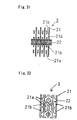
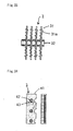
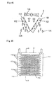
- the air heat exchanger may be characterized in that the fins are multiple sheets of plate fins located at predetermined intervals, the heat exchange pipes are disposed so that the pipes penetrate through the multiple plate fins, and the spaces between the fins are formed as air passages.
- the heat exchanger can not only be produced at a low cost, but also be used in wider applications.
- the plate fins may be formed as slit fins.
- frost or ice can be easily cut with slits during defrost operation.
- a mass of frost or ice attached to the heat exchange surface can be made suitably small and fall down easily by its own weight.
- the plate fins may be formed as louver fins.
- frost or ice can be cut with the top of louvers easily during defrost operation.
- a mass of frost or ice attached to the heat exchange surface can be made suitably small and fall down easily by its own weight.
- the plate fins may be formed as flat fins and provided with notches at the rear of the heat exchange pipes in the direction along which air passes.
- the plate fins may be provided with dimples on the surface.
- the area of the heat exchange surface of the fins for heat exchange with frost is large as compared with the amount of frost formed, interfacial frost or ice in the surface portions A can melt earlier, and the time for defrost operation can be further reduced.
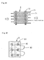
- the plate fins may have a large fin pitch formed at the ends from which air flows out.
- the plate fins may have a large fin pitch formed at the lower ends.
- frost or ice released and falling down by its own weight is not retained at the lower end of the heat exchanger, and the time for defrost operation can be surely reduced.
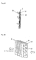
- the plate fins may be located so that the edges are made oblique in the air passages.
- the air heat exchanger By locating the air heat exchanger in this manner, when the air heat exchanger is used as an evaporator, water droplets condensed on and attached to the heat exchange surface can fall down easily. Further, in the case of defrost operation or the like of the heat exchanger, frost attached to the heat exchange surface can fall down easily by its own weight. Thus, the time for refrigerating operation can be further extended, and the time for defrost operation can be further reduced.
- the heat exchange pipes are preferably arranged in grids.
- frost or ice attached to the heat exchange surface can easily flow downwind, making it easy to carry out defrosting.
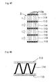
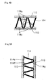
- the air heat exchanger of the present invention may be configured so that multiple rows of flat tubes are located as the heat exchange pipes, the fins are corrugate fins and are disposed so that the edge lines of the waveform parts of the corrugate fins are perpendicular to the heat exchange pipes, and the spaces formed in parallel with the edge lines of the waveform parts of the corrugate fins are formed as air passages.
- the surface of the corrugate fins has two kinds of surface portions discretely distributed, i.e. surface portions A with a low heat capacity and surface portions B to which frost or ice is poorly bound or attached, the heat exchange surface exhibits excellent water repellency and sliding properties.
- surface portions A with a low heat capacity and surface portions B to which frost or ice is poorly bound or attached the heat exchange surface exhibits excellent water repellency and sliding properties.
- water droplets or frost attached to the surface of the corrugate fins can be drifted downwind by the wind force.
- a stacked heat exchanger in which ventilation resistance of air is smaller than that of a heat exchanger using the above-described plate fins (specifically, a cross fin heat exchanger) and high-performance and inexpensive corrugate fins are used, can be used as an outdoor heat exchanger such as a heat pump air conditioner or a heat pump air conditioner for vehicle use.
- the air heat exchanger of the present invention may be formed so that the heat exchange pipes are disposed on the surface perpendicular to the direction along which air flows, and mesh fins are attached to the heat exchange pipes.
- the surface of the mesh fins used as an evaporator has two kinds of surface portions discretely distributed, i.e. surface portions A with a low heat capacity and surface portions B to which frost or ice is poorly bound or attached, the heat exchange surface exhibits excellent water repellency and sliding properties.
- condensed water attached to the surface of the mesh fins is made globular and can be blown off easily, and the mesh fins can be used without frosting for a long time. Accordingly, inexpensive mesh fins can be used at a high efficiency.
- the refrigeration apparatus of the present invention uses the above air heat exchanger.
- the refrigeration apparatus with such a configuration, can extend the time for refrigerating operation and reduce the time for defrost operation.
- the unit can exhibit an effect of refrigerating operation sufficiently and improve energy efficiency.
- the refrigeration apparatus may be a refrigeration apparatus configured as a heat pump air conditioner, the refrigeration apparatus in which the above air heat exchanger is used as an outdoor heat exchanger.
- the heat pump air conditioner with such a configuration can extend the time for heating operation and reduce the time for defrost operation.
- the unit can provide improved heating comfort and exhibit improved energy efficiency.
- the refrigeration apparatus may be a refrigeration apparatus configured as a heat pump air conditioner, the refrigeration apparatus in which the air heat exchangers are used as an indoor heat exchanger and an outdoor heat exchanger, respectively.
- the unit can not only exhibit the above effect, but also suppress formation of frost in the indoor heat exchanger during low-load cooling operation.
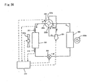
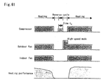
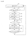
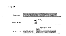
- the refrigeration apparatus of the present invention may be configured so that the unit comprises an evaporator consisting of the air heat exchanger having the above-described surface structure; a blower for blowing air to be heat-exchanged with the evaporator across the evaporator; a refrigerant circuit that can be operated in a defrost cycle in which a gas discharged from a compressor is supplied to the evaporator during defrost operation; and a control unit that, during defrost operation, stops the blower and activates the defrost cycle until interfacial frost or ice in contact with the surface portions A melts, and operates the blower and inactivates the defrost cycle after the interfacial frost or ice in contact with the surface portions A has melted.
- the unit comprises an evaporator consisting of the air heat exchanger having the above-described surface structure; a blower for blowing air to be heat-exchanged with the evaporator across the evaporator; a refriger
- condensed water condensed on and attached to the surface of the evaporator is made globular and thus is blown off easily by the pressure of wind passing through the evaporator, and is supercooled and thus frozen only with difficulty. Accordingly, the time for refrigerating operation until the amount of frost formed reduces the growth rate of frost attached to the heat exchange surface and requires defrosting (heating operation in the case of a heat pump air conditioner) can be extended.
- the evaporator of the present invention can reduce the amount of water droplets or frost remaining on the heat exchange surface of the evaporator after defrosting, the amount of frosting or freezing nuclei in refrigerating operation is reduced, and thus the time for refrigerating operation can be extended repeatedly, and the time for defrost operation can be reduced repeatedly. For this reason, the heat energy required for defrosting can be saved, and the time for defrost operation can be reduced.
- the blower is operated in defrost operation in which a gas discharged from a compressor is supplied to the evaporator, when interfacial frost or ice in contact with the heat exchange surface of the evaporator melts, frost or ice on the heat exchange surface can be blown off by the wind pressure.
- the time for defrost operation can be reduced, and the heat energy necessary for defrosting can be further reduced.
- the refrigeration apparatus of the present invention can prevent reduction in an effect of refrigerating operation (e.g. reduction in heating comfort when the unit is applied to a heat pump air conditioner) and suppress reduction in energy efficiency.
- the refrigeration apparatus of the present invention may be configured so that the unit comprises an evaporator having, as constituent members, fins with a surface for heat exchange with air comprising surface portions A and surface portions B, the surface portions A and the surface portions B having the feature 1 and the feature 2 as described above; a blower for blowing air to be heat-exchanged with the evaporator across the evaporator; a refrigerant circuit that can be operated in a defrost cycle in which a gas discharged from a compressor is supplied to the evaporator during defrost operation; and a control unit for controlling the apparatus during defrost operation to activate the defrost cycle and operate the blower.
- the unit comprises an evaporator having, as constituent members, fins with a surface for heat exchange with air comprising surface portions A and surface portions B, the surface portions A and the surface portions B having the feature 1 and the feature 2 as described above; a blower for blowing air to be heat-exchanged with the evaporator across the evapor
- the refrigeration apparatus with such a configuration is configured so that the fins of the evaporator have the surface structure as described above, and the blower is operated after interfacial frost or ice in contact with the surface portions A during defrost operation has melted, and thus can prevent reduction in an effect of refrigerating operation (e.g. reduction in heating comfort when the apparatus is applied to a heat pump air conditioner) and suppress reduction in energy efficiency as in the above-described refrigeration apparatus.
- the refrigeration apparatus activates the defrost cycle and stops the blower until interfacial frost or ice in contact with the surface portions A melts during defrost operation
- the blower blows wind only when frost or ice attached to the heat exchange surface is intended to be blown off by the wind pressure, and can further improve energy efficiency as compared with the above-described first solution means.
- the refrigeration apparatus of the present invention may be configured as a heat pump refrigeration apparatus which can be operated for heating and cooling, so that the apparatus comprises an evaporator consisting of the air heat exchanger having the above-described fin surface structure; a blower for blowing air to be heat-exchanged with the evaporator across the evaporator; a refrigerant circuit that can be operated in a defrost cycle in which a gas discharged from a compressor is supplied to the evaporator during defrost operation; and a control unit for controlling the apparatus to activate the defrost cycle during defrost operation and set the operation speed of the blower during the defrost operation at the highest of speeds that can be selected during heating operation.
- the refrigeration apparatus of the present invention may be configured as a heat pump refrigeration apparatus which can be operated for heating and cooling, so that the apparatus comprises an evaporator consisting of the air heat exchanger having the above-described fin surface structure; a blower for blowing air to be heat-exchanged with the evaporator across the evaporator; a refrigerant circuit that can be operated in a defrost cycle in which a gas discharged from a compressor is supplied to the evaporator during defrost operation; and a control unit for controlling the apparatus to activate the defrost cycle during defrost operation and set the operation speed of the blower during the defrost operation at a higher speed than the highest of speeds that can be selected during heating operation.
- frost or ice of the surface portions A having melted on the interface of the surface portions A can be blown off by the wind pressure, frost or ice attached to the surface portions B can be released earlier, and frost or ice can be released from the whole heat exchange surface.
- the refrigerant circuit may comprise a defrost cycle of a normal cycle hot gas bypass system.
- the normal cycle hot gas bypass system refers to a defrost cycle in which a gas discharged from a compressor is bypassed to the inlet of an evaporator, while circulating a refrigerant in a refrigerant circuit in heating operation, to heat the evaporator.
- heating operation can be switched to defrost operation while operating the compressor continuously without cessation, and the time for defrost operation can be reduced.
- the refrigerant circuit may comprise a defrost cycle of a reverse cycle system.
- the reverse cycle system refers to a defrost cycle during defrost operation in which a refrigerant is circulated in the direction reverse to that of normal refrigerating operation, specifically, heating operation in the case of a heat pump air conditioner, and an evaporator during heating operation functions as a condenser.
- a cycle during cooling operation can be used as it is.
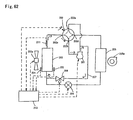
- the refrigerant circuit may comprise a defrost cycle of a simple hot gas bypass system.
- the simple hot gas bypass system refers to a defrost cycle during defrost operation in which an expansion mechanism for heating is closed, and a refrigerant discharged from a compressor is entirely circulated to the inlet of an evaporator directly.
- heating operation can be switched to defrost operation while operating the compressor continuously without cessation, and the time for defrost operation can be reduced.
- defrost operation since a large amount of the refrigerant is directly transferred to the evaporator from the compressor, heat energy accumulated on the high pressure side of the refrigerant circuit is discharged to the evaporator at a burst. Accordingly, interfacial frost or ice in contact with the surface portions A can melt in a short time, and the time for defrost operation can be reduced.
- frost or ice on the whole heat exchange surface has to be caused to melt, the amount of heat tends to be insufficient. In the present invention, however, it is only necessary to cause melting of frost or ice on the surface of the surface portions A (interfacial frost or ice), and thus heat energy does not lack.
- Embodiments of the present invention will be described below. First, the surface structure of the heat exchange surface in an air heat exchanger of the present invention will be described.
- the surface for heat exchange with air has two kinds of surface portions discretely distributed, i.e. surface portions A and surface portions B satisfying the following feature 1 and feature 2, and is formed as a surface structure exhibiting excellent easy frost/ice release properties.
- the feature 1 is a feature for detaching frost or ice easily in its entirety by first untying the relation in which the surface portions A adhere to and are bound to ice.
- frost or ice is not detached until melting occurs in a large part of the heat exchange surface.
- the surface structure of the present invention can make frost or ice detached in its entirety only by melting the interface in contact with the surface portions A.
- the surface portions B preferably has features such as, for example, water repellency and surface roughness, that make the surface portions B to which frost or ice is poorly bound or attached.
- the feature 2 can be exhibited regardless of whether frost or ice melts on the interface with the surface portions B or not.
- the feature 2 is a feature showing that frost or ice attached to the surface portions B can be released from the surface portions B even if the frost or ice does not necessarily melt.
- a feature is that frost or ice crystals on the surface portions B can be released integrally with frost or ice crystals having been detached from the surface portions A in advance. In a conventional heat exchange surface, interfacial frost or ice in contact with surface portions B has to be caused to melt before release.
- frost or ice can be easily removed only by applying a small amount of heat energy to the heat exchange surface to which frost or ice is attached.
- the heat exchange surface may have a surface portion other than the surface portions A and the surface portions B, but such a surface portion must not impair the feature 1 and feature 2 of the surface portions A and the surface portions B.
- the air heat exchanger may be defrosted by applying force to the heat exchanger (specifically, directly heating the heat exchanger itself) or by heating frost or ice from outside (e.g. by heat irradiation or sunlight). Any of the heating methods can cause frost or ice to be released from the heat exchanger having the surface structure of the present invention, though the required time differs.
- the area ratio, planar shape, and location of the surface portions A and the surface portions B, the three-dimensional shape of the surface portions, and the like are not specifically limited insofar as the above feature 1 and feature 2 are satisfied, but are preferably as follows.
- the area ratio of the surface portions A to the surface portions B can be selected in a wide range of 1/99 to 99/1. However, the ratio of the surface portions A is preferably as small as possible from the viewpoint of energy efficiency, insofar as the feature 2 can be exhibited.
- any planar shape or location of the surface portions is possible.
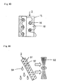
- Specific examples include a configuration in which the surface portions A and the surface portions B are arranged in stripes; a configuration in which the surface portions A and the surface portions B are located as islands; a configuration in which the surface portions A are dispersed in the surface portions B as spots or polka dots (or vice versa); a configuration in which the surface portions A are located on the surface portions B as lattices (or vise versa); and a configuration in which the surface portions A are located on the surface portions B as rings (or vise versa).
- the three-dimensional shape of the surface portions is not specifically limited, and may be planar, projected, or deformed.
- the surface portions may be in the shape of a terrace (or a diagonal board or circular board) in which one surface is higher than the other surface.
- Known methods can be applied to the forming method without specific limitations. Examples include (1) coating, (2) various moldings, (3) various chemical surface processings, (4) various physical surface processings, and (5) a method comprising forming a complex such as a layered product.
- the heat exchange surface is coated with the following surface treatment composition to form the surface structure of the present invention.
- Examples of the surface treatment composition used include a first surface treatment composition composed of:
- the surface treatment composition may be a second surface treatment composition composed of:
- the second to fourth surface treatment compositions are preferably surface treatment compositions that provide a film with an initial sliding angle of 15° or less, the sliding angle defined as an angle of a sample plate at which water droplets begin to roll down when 4 ⁇ L of distilled water is added dropwise onto the sample plate horizontally placed under environmental conditions of a temperature of 17 ⁇ 1°C and a relative humidity of 60 ⁇ 2% to form the water droplets, and then the sample plate is inclined at increasing angles with an increment of 0.1°.
- the surface portions A are formed by the inorganic particles with a low heat capacity (d), and the surface portions B are formed by the water-repellent binder resin (a) and the PTFE particles (b).
- the surface portions A are formed by the simple carbon substance, and the surface portions B are formed by the water-repellent binder resin (A).
- the water-repellent binder resin (a) may be a resin that is water repellent and can maintain the PTFE particles (b) and the inorganic particles with a low heat capacity (d) to be uniformly dispersed.
- the water-repellent binder resin (A) may be a resin that is water repellent and sets the sliding angle of the surface of a film obtained from the composition of the present invention (definition (1): 4 ⁇ L water droplets, initial time, hereinafter the same) at 15° or less, preferably 10° or less, more preferably 7° or less, particularly 5° or less, and more particularly 3° or less.
- the resin (A) is preferably a resin that sets the sliding angle of ultrafine water droplet (definition (2): 1 ⁇ L water droplets, initial time, hereinafter the same) at 15° or less, preferably 12° or less, more preferably 10° or less, particularly 7° or less, and more particularly 5° or less.
- the sliding angle of 1 ⁇ L ultrafine water droplets is more useful as an index for evaluating the state of the coating surface than the sliding angle of 4 ⁇ L water droplets measured.
- the contact angle with water is preferably large.
- the surface portions B or the surface of a film obtained from the composition of the present invention has a contact angle with water of 140° or more.
- the angle is preferably 100° or more in order to easily provide the treated surface with the target water repellency.
- the upper limit is theoretically 180°.
- water-repellent binder resins (a) and (A) include a fluororesin, a silicone resin, and a urethane resin.
- a fluororesin is preferable because of its excellent dispersibility of PTFE particles or a simple carbon substance and the like.
- the fluororesin can be selected from conventional fluororesins, but is preferably a copolymer comprising tetrafluoroethylene (TFE), chlorotrifluoroethylene (CTFE), or hexafluoropropylene (HFP) as a main component due to its advantageous weather resistance, paint making, solubility in a solvent, and the like.
- TFE tetrafluoroethylene
- CFE chlorotrifluoroethylene
- HFP hexafluoropropylene
- fluororesins examples include the following resins.
- Typical examples of the structural unit (6-3) based on a monomer having a chemically curable group include a vinyl monomer of which the curable group is a hydroxyl group, carboxyl group, epoxy group, silyl group, or the like.
- Examples of the vinyl monomer of which the curable group is a hydroxyl group include hydroxyalkyl vinyl ether and hydroxyalkyl vinyl ester.
- carboxyl group-containing vinyl monomer examples include crotonic acid, maleic acid, acrylic acid, methacrylic acid, itaconic acid, and vinylacetic acid, or monomers derived from these acids.
- silyl group-containing vinyl monomer examples include vinyl monomers described in Japanese Laid-Open Patent Publication No. 61-141713, for example, vinyltrimethoxysilane, vinyltriethoxysilane, vinyltripropoxysilane, vinylmethyldimethoxysilane, vinyldimethylmethoxysilane, vinylmethyldiethoxysilane, vinyltris( ⁇ -methoxy)silane, trimethoxysilylethyl vinyl ether, triethoxysilylethyl vinyl ether, trimethoxysilylbutyl vinyl ether, triethoxysilylbutyl vinyl ether, trimethoxysilylpropyl vinyl ether, triethoxysilylpropyl vinyl ether, vinyltriisopropenyloxysilane, vinylmethyldiisopropenyloxysilane, triisopropenyloxysilylethyl vinyl ether, triisopropenyloxysilylpropyl vinyl ether,
- CTFE/isobutylene (IB)/HBVE/vinyl propionate (VPi) copolymer a CTFE/IB/hydroxyethyl allyl ether (HEAE)/VAc copolymer
- HEAE hydroxyethyl allyl ether
- TFE/IB/HBVE/VPi copolymer a CTFE/IB/HBVE/VeoVa 9 (manufactured by a Shell Chemicals Ltd., trade name) copolymer
- TFE/IB/HBVE/VBz copolymer a CTFE/IB/HBVE/diethyl maleate (DEM) copolymer
- TFE/IB/HBVE/VeoVa 9/dibutyl maleate (DBM) copolymer a CTFE/IB/HBVE/diethyl fumarate (DEF) copolymer
- Examples of commercially available products comprising the fluororesins (1) to (6) include ZEFFLE (manufactured by Daikin Industries, Ltd.), LUMIFLON (manufactured by Asahi Glass Company), FLUONATE (manufactured by Dainippon Ink and Chemicals, Inc.), and CEFRAL COAT (manufactured by Central Glass Co., Ltd.).
- the fluorine-containing copolymer (6) is preferable in terms of weather resistance.
- a resin suitable for the water-repellent binder resins (a) and (A) other than the fluororesins include a silicone resin which may be fluorinated.
- the PTFE particles (b) preferably have a weight average molecular weight of 500 to 500,000. Since conventional PTFE, having a weight average molecular weight of 1,000,000 to 10,000,000, is fibrillated when a shearing force is applied, PTFE used in the present invention preferably has a molecular weight in the above range.
- the weight average molecular weight is preferably 600 or more, and particularly 5,000 or more, and is preferably 500,000 or less, more preferably 200,000 or less, and still more preferably 12,000 or less.
- the mean particle diameter is preferably 0.05 ⁇ m to 10 ⁇ m.
- the mean particle diameter is preferably 0.1 ⁇ m or more, and more preferably 0.2 ⁇ m or more, and is preferably 7 ⁇ m or less, and more preferably 5 ⁇ m or less.
- PTFE may be a tetrafluoroethylene (TFE) homopolymer or modified PTFE modified by a known modifier.
- TFE tetrafluoroethylene
- PTFE particles have an unstable group at the molecular terminal due to a polymerization initiator or the like, but it is preferable to completely fluorinate such a terminal group to stabilize the PTFE particles.
- Particularly preferable PTFE particles have a terminal group completely fluorinated, and have a weight average molecular weight of 500 to 20,000 and a mean particle diameter of 2 to 10 ⁇ m.
- Examples of commercially available products of the PTFE particles (b) include LUBRON manufactured by Daikin Industries Ltd. and CEFRAL LUBE manufactured by Central Glass Co., Ltd.
- the second to fourth surface treatment compositions of the present invention do not necessarily have to comprise the PTFE particles in order to reduce the material cost for the surface treatment compositions themselves.
- the dispersing agent (c) makes the PTFE particles (b) uniformly dispersed in the water-repellent binder (a). It is necessary for the dispersing agent used here not only to make the PTFE particles (b) dispersed in the solvent if used, but also to make the PTFE particles (b) uniformly dispersed in the water-repellent binder resin in a film. Accordingly, the suitable dispersing agent is selected taking the types of the PTFE particles (b) and the water-repellent binder resin (a) as well as the type of the solvent (e).
- the simple carbon substance (B) described later cannot be easily dispersed in the water-repellent binder resin (A).
- the simple carbon substance (B) can be dispersed uniformly in the water-repellent binder resin (A) (dispersing action in a resin).
- the dispersing agent is attached to (or adsorbed on) the surface of the simple carbon substance (B) so that the simple carbon substance (B) has increased water and oil repellency (water and oil-repellent action).
- the dispersing agent when the solvent (e) is used, the dispersing agent also makes the simple carbon substance (B) uniformly dispersed in the solvent (e) (dispersing action in a solvent).
- the suitable dispersing agent (C) is selected taking the types of the simple carbon substance (B) and the water-repellent binder resin (A) into consideration as well as the type of the solvent (e) if used. If the solvent is not used, it is only necessary to take the components (A) and (B) into consideration when a paint powder is to be prepared.
- the dispersing agent is preferably a polymer (C1) comprising a recurrent unit derived from a vinyl monomer having a fluoroalkyl group.
- the dispersing agent is a copolymer of a vinyl monomer having a fluoroalkyl group with a non-fluorine vinyl monomer.
- the fluoroalkyl group-containing (meth)acrylates may be used in a mixture of two or more.
- non-fluorine monomer examples include a (meth)acrylate and a polymerizable cyclic carboxylic anhydride.
- the (meth)acrylate may be an ester of (meth)acrylic acid with an aliphatic alcohol, for example, a monohydric alcohol or a polyhydric alcohol (for example, a dihydric alcohol).
- polymerizable cyclic carboxylic anhydride examples include polymerizable cyclic carboxylic anhydrides described in Japanese Laid-Open Patent Publication No. 2001-158811.
- non-fluorine monomer examples include the following monomers:
- Examples of the polymerizable cyclic carboxylic anhydride include maleic anhydride, citraconic anhydride, itaconic anhydride, maleated methylcyclohexane tetrabasic acid anhydride, methyltetrahydrophthalic anhydride, endomethylenetetrahydrophthalic anhydride, methylendomethylenetetrahydrophthalic anhydride, and chlorendic anhydride, and their derivatives.
- the non-fluorine monomer may be a silicon monomer (for example, a (meth)acryloyl group-containing alkylsilane, (meth)acryloyl group-containing alkoxysilane, or (meth)acryloyl group-containing polysiloxane).
- a silicon monomer for example, a (meth)acryloyl group-containing alkylsilane, (meth)acryloyl group-containing alkoxysilane, or (meth)acryloyl group-containing polysiloxane.
- the fluorine-containing polymer (C1) can be produced by radical polymerization.
- the polymer (C1) may be a chain polymer or a graft copolymer.
- the graft copolymer include a graft copolymer described in the above-mentioned Japanese Laid-Open Patent Publication No. 2001-158811, which has a recurring unit derived from a vinyl monomer having a perfluoroalkyl group and a recurring unit derived from a polymerizable cyclic carboxylic anhydride; and a graft copolymer described in WO 01/19884, which has a non-fluorine backbone polymer and a fluorine-containing graft chain.
- the weight average molecular weight is preferably 3,000 or more, more preferably 5,000 or more, and particularly preferably 7,000 or more, and is preferably 30,000 or less, more preferably 20,000 or less, and particularly preferably 15,000 or less.
- the dispersing agent (C) used may be, in addition to the fluorine-containing polymer, silicone oil or fluorinated silicone oil in a combination with other components.
- the dispersing agent may be a solid, liquid, or gas at room temperature (about 25°C), as long as the agent has the above actions (dispersing action in a resin, water and oil-repellent action, and, if necessary, dispersing action in a solvent).
- the dispersing agent is preferably a liquid, because a liquid can be easily handled.
- Examples of commercially available products of the fluorine-containing polymer include, but are not limited to, UNIDYNE series composed of a fluorine-containing graft copolymer (such as TG-656 and TG-652, both manufactured by Daikin Industries, Ltd.), FTONE series composed of a fluorine-containing polymer (such as GM-105, manufactured by Daikin Industries, Ltd.), ASAHI GUARD (such as AG-5850, manufactured by Asahi Glass Co., Ltd.), and NOXGUARD (such as ST-320, manufactured by NOK Corp.).
- Examples of commercially available silicone products include SD8000, SH200, and SH1107 manufactured by Dow Corning Toray Silicone Co., Ltd., and KF96 and KF99 manufactured by Shin-Etsu Chemical Co., Ltd.
- the amount of the dispersing agent (C) added is advantageously 5 parts by weight or more, more advantageously 10 parts by weight or more, and particularly advantageously 20 parts by weight or more based on 100 parts by weight of the water-repellent binder resin (A) in order to obtain an effect by the addition, and is preferably 100 parts by weight or less, more preferably 80 parts by weight or less, and particularly preferably 60 parts by weight or less in order to, for example, reduce the material cost.
- the inorganic particles with a low heat capacity (d) correspond to particles of many metal or nonmetal elements and particles of some metallic compounds. Specific examples include metals such as gold, silver, aluminum, iron, and copper; and nonmetals such as carbon and boron; as well as metallic compounds.
- the inorganic particles with a low heat capacity (d) are preferably conductive.
- Many of water-repellent binders are electrostatic, and allow dusts as freezing nuclei to be attached to the surface of a film easily. Therefore, by preventing charging of the surface of a film, formation of ice (snow) can be further prevented.
- the inorganic particles with a low heat capacity preferably have excellent weather resistance, corrosion resistance, and solvent resistance.
- the inorganic particles with a low heat capacity (d) preferably have a molar heat capacity of 7 Ca/JK -1 mol -1 or less.
- the lower limit is typically 6 Ca/JK -1 mol -1 .
- the inorganic particles with a low heat capacity (d) preferably have a primary mean particle diameter of 2 ⁇ m to 12 ⁇ m in terms of dispersibility.
- carbon black as a carbon element more particularly, crystalline carbon black is particularly preferable.
- the composition When the inorganic particles with a low heat capacity (d) are added, the composition exhibits further improved sliding properties, regardless of whether or not the composition is water-repellent, although the reason is not clear. In addition, an action for defrosting easier when frosted can be expected.
- the simple carbon substance (B) used in the present invention is, as described above,
- the amount of DBP absorbed is 45 cm 3 /100 g or more, and preferably 60 cm 3 /100 g or more.
- the upper limit is 450 cm 3 /100 g.
- the amount of DBP absorbed is small, the development level of the structure is low, and the sliding angle tends to be large depending on the combination with the dispersing agent (C). If the amount of DBP absorbed is large, the development level of the structure is high, which requires a design for uniform dispersion.
- the specific surface area by nitrogen adsorption is 30 m 2 /g or more.
- the upper limit is 400 m 2 /g.
- the specific surface area by nitrogen adsorption is small, the specific surface area is small, and the sliding angle tends to be large depending on the combination with the dispersing agent (C). If the specific surface area by nitrogen adsorption is large, the specific surface area is large, which requires a design for uniform dispersion.
- the specific surface area by nitrogen adsorption almost corresponds with the specific surface area, and almost corresponds with the particle diameter when the simple carbon substance is particles.
- the mean particle diameter of particles of the simple carbon substance with a specific surface area by nitrogen adsorption of 30 m 2 /g corresponds to about 60 nm
- the mean particle diameter of particles of the simple carbon substance with a specific surface area by nitrogen adsorption of 400 m 2 /g corresponds to about 10 nm.
- the particularly preferable simple carbon substance (B) used in the present invention which exhibits an excellent effect of preventing formation of ice (snow) (has a small sliding angle), is the substance (B-3) that has DBP absorbed in an amount in the above range and a specific surface area by nitrogen adsorption in the above range in combination.
- the simple carbon substance (B) that can be used include carbon black, carbon nanotube, natural graphite, fullerene, and carbon nanohorn, all of which have DBP absorbed in an amount and/or a specific surface area by nitrogen adsorption in the above specific ranges.
- carbon black examples include, but are not limited to, furnace black, channel black, thermal black, lamp black, and acetylene black.
- Carbon nanotube and carbon nanohorn absorb DBP in an amount of about 400 cm 3 /100 g.
- the amount of the simple carbon substance (B) added is advantageously 25 parts by weight or more, more advantageously 40 parts by weight or more, and particularly advantageously 60 parts by weight or more based on 100 parts by weight of the water-repellent binder resin (A) in order to obtain an effect by the addition, and is preferably 400 parts by weight or less, more preferably 200 parts by weight or less, and particularly preferably 150 parts by weight or less in order to, for example, ensure good dispersion and reduce the material cost.
- a solvent is useful for uniformly mixing the components of the surface treatment composition easily, forming a film easily, and uniformly dispersing various components in the water-repellent binder resins (a) and (A). Accordingly, the solvent (e) and the solvent used in the various surface treatment compositions of the present invention (hereinafter simply called solvent (e)) are selected taking the other components (a), (b), (c), and (d) and, furthermore, the components (A), (B), and (C) into consideration.
- the solvent (e) may be an inorganic solvent system such as water, but is preferably an organic solvent system in terms of the above aspects.
- the organic solvent system may be a single solvent or a system in which two or more solvents are mixed. When two or more solvents are used, the system preferably contains a polar organic solvent and a non-polar organic solvent so that the other components can be further uniformly dispersed.
- polar organic solvent examples include butyl acetate, ethyl acetate, acetone, methyl isobutyl ketone, ethanol, isopropanol, butanol, and ethylene glycol monoalkyl ether.
- non-polar organic solvent examples include toluene, xylene, n-hexane, cyclohexane, and heptane, as well as turpentine as a petroleum spirit.
- butyl acetate by mixing butyl acetate with a petroleum solvent (such as toluene, xylene, n-hexane, cyclohexane, heptane, or turpentine) for use, water sliding properties of the resulting film can be adjusted.
- a petroleum solvent such as toluene, xylene, n-hexane, cyclohexane, heptane, or turpentine
- the mixing ratio differs according to the types of the solvents used in combination and is arbitrary, but butyl acetate is preferably equal to or larger than the petroleum solvent on a weight basis in order to ensure good water sliding properties.
- the PTFE particles (b) are added in an amount of 100 parts by weight to 200 parts by weight, and the dispersing agent (c) is added in an amount of 5 parts by weight to 30 parts by weight, based on 100 parts by weight (hereinafter the same unless otherwise specified) of the water-repellent binder resin (a).
- the inorganic particles with a low heat capacity (d) are preferably added in an amount of 25 parts by weight to 200 parts by weight, and the solvent (e) is preferably added in an amount of 400 parts by weight to 2,000 parts by weight.
- the resin in the case of an outdoor application such as a solar panel cover in which icing and deicing are repeated due to the difference between temperatures or amounts of sunshine, it is desired to increase the strength of the film to maintain sliding properties for a long time. For this reason, the resin is desirably crosslinked.
- crosslinking can be achieved by irradiation with high energy rays or the like without using the crosslinking agent (E)
- binder resin having a chemically curable group examples include, but are not limited to, the above fluororesin having a chemically curable group, as well as a silicone resin, polyester resin, polyolefin resin, acrylic resin, and polyurethane resin having a chemically curable group.
- the crosslinking agent (E) may be a crosslinking agent that reacts with the curable group of the resin having a curable group to cure the resin.
- the agent usually used include an isocyanate compound, an amino resin, an acid anhydride, a polysilane compound, a polyepoxy compound, and an isocyanate group-containing silane compound.
- isocyanate compound examples include, but are not limited to, 2,4-tolylene diisocyanate, diphenylmethane-4,4-diisocyanate, xylylene diisocyanate, isophorone diisocyanate, lysine methyl ester diisocyanate, methylcyclohexyl diisocyanate, trimethylhexamethylene diisocyanate, hexamethylene diisocyanate, and n-pentane-1,4-diisocyanate; their trimers; their adducts or burets; their polymers having two or more isocyanate groups; and blocked isocyanates.
- amino resin examples include, but are not limited to, a urea resin, a melamine resin, a benzoguanamine resin, a glycoluril resin; a methylolated melamine resin obtained by methylolating melamine; and an alkyl etherified melamine resin obtained by etherifying methylolated melamine with an alcohol such as methanol, ethanol, or butanol.
- Examples of the acid anhydride include, but are not limited to, phthalic anhydride, pyromellitic anhydride, and mellitic anhydride.
- the polysilane compound is a compound having two or more groups selected from hydrolyzable groups directly bonded to a silicon atom and a SiOH group, or a condensate thereof.
- Examples of the compound that can be used include compounds described in Japanese Laid-Open Patent Publication No. 2-232250 and Japanese Laid-Open Patent Publication No. 2-232251.
- polyepoxy compound or the isocyanate group-containing silane compound compounds described in Japanese Laid-Open Patent Publication No. 2-232250 and Japanese Laid-Open Patent Publication No. 2-232251 can be used, for example.
- Preferable specific examples include the following compounds: OCNC 3 H 6 Si (OC 2 H 5 ) 3 , and OCNC 2 H 4 Si (OCH 3 ) 3 .
- the crosslinking agent (E) is added in an amount of 0.1 equivalent or more, and preferably 0.5 equivalent or more, and 5 equivalents or less, and preferably 1.5 equivalents or less based on one equivalent of the curable group in the curable group-containing binder resin.
- an accelerator may be used.
- the accelerator include an organotin compound, an acidic phosphate, a reaction product of an acidic phosphate with an amine compound, an amine compound, and lead octylate.
- the accelerators may be used singly or in a combination of two or more.
- the amount of the accelerator added is 1.0 ⁇ 10 -6 parts by weight or more, and preferably 5.0 ⁇ 10 -5 parts by weight or more, and 1.0 ⁇ 10 -2 parts by weight or less, and preferably 1.0 ⁇ 10 -3 parts by weight or less based on 100 parts by weight of the binder resin (A).
- the surface treatment composition of the present invention can be prepared into various forms that can form a film.
- the composition is preferably prepared into a powder paint or a solvent-type paint, more particularly, a solvent-type paint, in particular, an organic solvent-type paint, because a film can be formed easily.
- the surface treatment composition of the present invention preferably has a solid concentration of 5 to 40 wt%, and particularly 15 to 30 wt% in terms of applicability and dispersibility.
- the second to fourth surface treatment compositions of the present invention are composed of the water-repellent binder resin (A), the simple carbon substance (B), and the dispersing agent (C) as essential components. If necessary, the compositions are composed of, in addition to the components (A) to (C), the solvent (e) and the accelerator.
- Examples of such an additive that does not impair the object of the present invention include a pigment, other resins, other dispersing agents, a flow adjuster, an anti-flooding agent, an antioxidant, and a UV absorber.
- the surface treatment composition as a solvent-type paint is prepared by feeding each component into the solvent (e) and stirring the components sufficiently.
- the stirring method is not specifically limited, but is preferably ultrasonic stirring or forced stirring, because such a method can uniformly disperse particle components such as the PTFE particles (b) and the inorganic particles with a low heat capacity (d) easily.
- the stirring method may comprise feeding each component into the solvent (e) and mixing the components sufficiently, or may comprise pretreating the simple carbon substance (B) with the dispersing agent (C), feeding the dispersion into the solvent (e) together with the binder resin (A), and mixing the components sufficiently.
- the stirring method is not specifically limited, but is preferably ultrasonic stirring or forced stirring, because such a method can uniformly disperse solid components such as the simple carbon substance (B) easily.
- composition When the composition is prepared into a powder paint, it is preferable to pretreat the simple carbon substance (B) with the dispersing agent (C) and then mix the dispersion with the binder resin (A).
- the coating method methods such as, for example, dip coating, bar coating, roll down coating, and spraying can be employed without specific limitations.
- the film After coating, the film is dried at room temperature or dried with heat if necessary to form a cured film.
- the film thickness of the film may be appropriately selected according to the part to which the film is applied. Usually, however, the thickness is preferable 0.1 ⁇ m or more, and more preferably 1 ⁇ m or more, and is preferably 0.2 mm or less, and more preferably 0.1 mm or less.
- the substrate to which the film is applied is determined according to the type of the heat exchanger having a frosting problem without specific limitations. Examples include aluminum, stainless steel, copper, various alloys, and ceramics.
- the resulting film (surface structure with the heat exchange surface formed) can provide the heat exchange surface with the surface portions A and the surface portions B, and can have easy frost/ice release properties, for example.
- the film can provide with the heat exchange surface with a sliding angle (4 ⁇ L water droplets) of 15° or less, further 10° or less, preferably 7° or less, particularly 5° or less, and more particularly 3° or less.
- the surface of the film can be provided with a contact angle with water of 140° or more, further 145° or more, and particularly 150° or more.
- the sliding angle of ultrafine water droplets (1 ⁇ L water droplets) is 15° or less, preferably 12° or less, more preferably 10° or less, particularly 7° or less, and more particularly 5° or less. As the sliding angle is closer to 0° (at which the film is horizontal), water sliding properties are more excellent.
- the film with such surface properties can make water microdroplets formed on the water-repellent surface slide easily, avoid formation of nuclei for formation of ice (snow, frost), and exhibit an improved effect of preventing formation of ice (snow or frost).
- ZEFFLE GK-510 manufactured by Daikin Industries, Ltd. was used as a water-repellent binder resin (a), CEFRAL LUBE (trade name, modified PTFE with a mean primary particle diameter of 5 to 10 ⁇ m, weight average molecular weight: 1,500 to 20,000) manufactured by Central Glass Co., Ltd. was used as PTFE particles (b), and UNIDYNE TG-656 manufactured by Daikin Industries, Ltd. was used as a dispersing agent (c). Amounts described in Table 1 of the components were fed into an organic solvent (e) shown in Table 1, and the components were stirred and mixed using ultrasonic stirring to prepare a surface treatment composition.
- e organic solvent
- the resulting surface treatment composition was applied to an aluminum plate (A1200 of JIS H4000, 100 mm ⁇ 100 mm) by spraying, and the film was left alone at room temperature for one day to cure the film. Then, the surface of the film was dried without washing to prepare a coating plate for the test (film thickness of the film: 20 ⁇ m).
- the contact angle with water was measured as follows.
- the angle was measured in accordance with JIS R3257 with a contact angle measuring device manufactured by Kyowa Interface Science Co., Ltd. (CA-VP, trade name) at a temperature of 15 to 20°C and at a relative humidity of 50 to 70%. As the contact angle with water is lager, water repellency is higher.
- the sliding angle was measured as follows.
- the coating plate was horizontally fixed to a contact angle measuring device manufactured by Kyowa Interface Science Co., Ltd. (CA-VP, trade name). 4 ⁇ L of distilled water was added dropwise onto the sample plate horizontally placed under environmental conditions of a temperature of 17 ⁇ 1°C and a relative humidity of 60 ⁇ 2% to form water droplets. Then, the sample plate was inclined at increasing angles with an increment of 0.1° to measure the angle of the sample plate at which the water droplets began to roll down. Measurement values shown in Table 1 are initial sliding angles. As the sliding angle is smaller, water droplet sliding properties (water sliding properties) are better.
- a surface treatment composition was prepared and applied to prepare a coating plate for the test in the same manner as in Test Example 1, except that, in the above Comparative Test Example 1, the components (a), (b), (c), and (e) were added at a ratio shown in Table 2, and particles shown in Table 2 were further added as inorganic particles with a low heat capacity (d) in an amount shown in the same table.
- the stirring method ultrasonic stirring was employed.
- the inorganic particles with a low heat capacity (d) in Table 2 are as follows.
- ZEFFLE GK-510 manufactured by Daikin Industries, Ltd. was used as a water-repellent binder resin (a), 4.0 g of CEFRAL LUBE (trade name, modified PTFE with a mean primary particle diameter of 5 to 10 ⁇ m, weight average molecular weight: 1,500 to 20,000) manufactured by Central Glass Co., Ltd. was used as PTFE particles (b), 4.0 g of UNIDYNE TG-656 manufactured by Daikin Industries, Ltd. was used as a dispersing agent (c), and 2.0 g of carbon black (manufactured by Sigma-Aldrich Co., mean particle diameter: 2 to 12 ⁇ m) was used as inorganic particles with a low heat capacity (d).
- the components were fed into a mixed solvent of 20 g of butyl acetate and 20 g of heptane, and the components were stirred and mixed using ultrasonic stirring to prepare a surface treatment composition.
- the resulting surface treatment composition was applied to an aluminum plate (A1200 of JIS H4000, 100 mm ⁇ 100 mm) by spraying, and the film was left alone at room temperature for one day to cure the film. Then, the surface of the film was dried without washing to prepare a coating plate for the test (film thickness of the film: 20 to 30 ⁇ m).
- the contact angle with water and the sliding angle (4 ⁇ L) were examined for the coating plate in the same manner as in Comparative Test Example 1 as described above to find that the contact angle with water was 152.1° and the sliding angle was 4.6°.
- the sample plate is vertically fixed in a wind tunnel, and the surface temperature of the sample plate is maintained at -7 ⁇ 2°C.
- the surface of the sample plate is heated to 5°C immediately after the frost operation to initiate defrost operation.
- the same air as in the frost operation is caused to flow under the same conditions.
- the defrost operation lasts for two minutes.
- Photographs taken by a CCD camera of the state of the surface of the sample plate when the defrost operation of the second cycle finished two minutes after the defrost operation started are shown in Fig. 13 (overall) and Fig. 14 (enlarged). As is clear from these photographs, no water droplets could be visually observed on the surface of the sample plate as well after the defrost operation of the second cycle finished.
- a surface treatment composition prepared was used to prepare a sample plate in the same manner as in Test Example 3, and a frost-defrost test was carried out in the same manner as in Test Example 3, except that, in Test Example 3, the inorganic particles with a low heat capacity (d) were not added.
- the results were as follows.
- Photographs taken by a CCD camera of the state of the surface of the sample plate when the defrost operation of the second cycle finished two minutes after the defrost operation started are shown in Fig. 27 (overall) and Fig. 28 (enlarged). As is clear from these photographs, many more large or small water droplets remained on the surface as compared with the surface when the above-described first defrost operation finished.
- binder resin A1 a TFE copolymer having a chemically curable group
- binder resin A1 a water-repellent binder resin
- B1 to B16 a simple carbon substance
- C a dispersing agent
- Each of the resulting surface treatment composition was applied to an aluminum plate (A1200 of JIS H4000, 100 mm ⁇ 100 mm) by spraying, and the film was left alone at room temperature for one day to cure the film. Then, the surface of the film was dried without washing to prepare a coating plate for the test (film thickness of the film: 20 ⁇ m).
- film thickness of the film 20 ⁇ m.
- the contact angle with water and the sliding angle (4 ⁇ L) were examined by the above methods, and the sliding angle of ultrafine water droplets (1 ⁇ L) was examined by the following method. The results are shown in Table 4.
- the coating plate is horizontally fixed to a contact angle measuring device manufactured by Kyowa Interface Science Co., Ltd. (CA-VP, trade name). 1 ⁇ L of distilled water is added dropwise onto the sample plate horizontally placed under environmental conditions of a temperature of 17 ⁇ 1°C and a relative humidity of 60 ⁇ 2%, using a pneumatic delivery syringe (precision needle valve micro-dispenser, 740MD-SS manufactured by EDF of the United States, trade name) to form water droplets. Then, the sample plate is inclined at increasing angles with an increment of 0.1° to measure the angle of the sample plate at which the water droplets begin to roll down. Measurement values shown in Table 4 are initial sliding angles of ultrafine water droplets.
- a surface treatment composition was prepared in the same manner as in Test Example 4, except that, in the experiment No. X1-3 of Test Example 4, a TFE copolymer not having a chemically curable group (hereinafter called "binder resin A2”) was used as a binder resin.
- the composition was applied in the same manner as in Test Example 4, and the resulting film was left alone at room temperature for 24 hours to prepare a coating plate for the test.
- a surface treatment composition was prepared in the same manner as in Test Example 4, except that, in the experiment No. X1-3 of Test Example 4, 3.2 parts by weight of the binder resin A1 having a chemically curable group and 0.8 part by weight of the binder resin A2 not having a chemically curable group were used as binder resins.
- the composition was applied in the same manner as in Test Example 4, and the resulting film was left alone at room temperature for 24 hours to prepare a coating plate for the test.
- the binder resin A1 containing a chemically curable group was used as a water-repellent binder resin (A)
- the carbon black particles B3 were used as a simple carbon substance (B)
- the fluorine-containing graft copolymer (C-1) was used as a dispersing agent (C)
- an isocyanate crosslinking agent was used as a crosslinking agent (E).
- Amounts described in Table 5 (the same as in the experiment No. X1-3 of Test Example 4 except for the crosslinking agent) of the components were fed into butyl acetate/heptane (1/1, weight ratio), and the components were stirred and mixed using ultrasonic stirring to prepare a surface treatment composition.
- the resulting surface treatment composition was applied to an aluminum plate (A1200 of JIS H4000, 100 mm ⁇ 100 mm) by spraying, and the film was left alone at room temperature for 24 hours to cure the film. Then, the surface of the film was dried without washing to prepare a coating plate for the test (film thickness of the film: 20 ⁇ m).
- a surface treatment composition was prepared in the same manner as in Test Example 4, except that, in the experiment No. X1-3 of Test Example 4, compounds shown in Table 4 (C-1 to C-4) were used as a dispersing agent (C).
- the composition was applied in the same manner as in Test Example 4, and the resulting film was left alone at room temperature for 24 hours to prepare a coating plate for the test.
- the dispersing agents in Table 7 are as follows.
- the heat exchange surface exhibit excellent water repellency, water sliding properties, and easy frost/ice release properties.
- Fig. 29 is a view showing a refrigerant circuit of the refrigeration apparatus of Embodiment 1.
- Fig. 30 is a perspective view showing an outdoor heat exchanger used in the same refrigeration apparatus.
- the refrigeration apparatus of Embodiment 1 is a separate heat pump air conditioner, as shown in Fig. 29.
- the discharge side and the suction side of a compressor 1 are connected to a discharge port 2a and a suction port 2b of a four-way selector valve 2.
- an outdoor heat exchanger 3 Between switching ports 2c and 2d of the four-way selector valve 2, an outdoor heat exchanger 3, an expansion mechanism 4, and an indoor heat exchanger 5 are connected to each other.
- the compressor 1, the four-way selector valve 2, and the outdoor heat exchanger 3 are stored in an outdoor unit 11, and the indoor heat exchanger 5 is stored in an indoor unit 12.
- the indoor heat exchanger 5 functions as an evaporator
- the outdoor heat exchanger 3 functions as a condenser.
- a refrigerant is caused to flow as indicated by the broken arrow shown in Fig. 29, so that the indoor heat exchanger 5 functions as a condenser, and the outdoor heat exchanger 3 functions as an evaporator.
- the outdoor heat exchanger 3 is frosted when refrigerating operation is maintained.
- the outdoor heat exchanger 3 is, as shown in Fig. 30, an air heat exchanger having flat plate fins (flat fins) 15 and heat exchange pipes 16 that are thermally conductively connected to the flat plate fins 15, specifically, inserted into heat exchange pipe holes of the flat plate fins 15.
- On the heat exchange surface specifically, the surface of the flat plate fins 15, a surface structure coated with the above-described surface treatment composition.
- the heat exchange surface of the outdoor heat exchanger 3 exhibits excellent water repellency and sliding properties.
- condensed water condensed on and attached to the surface of the outdoor heat exchanger 3 is made globular, and thus is blown off easily by the pressure of wind passing through the outdoor heat exchanger 3.
- the condensed water attached to the heat exchange surface is supercooled, and is thus frozen only with difficulty. Accordingly, the growth rate of frost attached to the heat exchange surface of the outdoor heat exchanger 3 can be reduced, and the time for heating operation until the amount of frost formed requires defrosting can be extended.
- the heat exchange surface of the outdoor heat exchanger 3 has the surface portions A and the surface portions B discretely distributed, during defrost operation, frost or ice on the surface portions A is released by melting interfacial frost or ice in contact with the surface portions A. Further, the released frost or ice and frost or ice on the surface portions B are at least partially bound to each other, and the frost or ice on the surface portions B is released by its own weight. Accordingly, in the air heat exchanger, it is not necessary to thoroughly melt frost or ice attached to the heat exchange surface as in a conventional one, and the time for defrost operation can be reduced.
- the heat exchange surface of the outdoor heat exchanger 3 has easy frost/ice release properties, during defrost operation, frost or ice on the heat exchange surface is released (detached) as a mass by its own weight, and thus no water droplets remain on the heat exchange surface from which the frost or ice has melted or has been released.
- the amount of frost or ice formed after resuming refrigerating operation can be reduced, the time for refrigerating operation can be extended continuously, and the time for defrost operation can be reduced continuously.
- the outdoor heat exchanger 3 comprises the flat plate fins 15, and thus can be produced at a low cost and used in wide applications.
- this embodiment can extend the time for heating operation and reduce the time for defrost operation.
- the embodiment can provide improved heating comfort and exhibit improved energy efficiency.
- Embodiment 2 is a refrigeration apparatus using slit plate fins (slit fins) 21 instead of the flat plate fins 15 in Embodiment 1.
- Fig. 31 is a cross-sectional view of an outdoor heat exchanger 3 of the refrigeration apparatus of this Embodiment 2 cut with the cross-section of slit plate fins 21.
- Fig. 32 is a cross-sectional view of an outdoor heat exchanger 3 of the refrigeration apparatus of Embodiment 2 cut with the plane of a slit plate fin 21.
- Fig. 32 shows only the slit plate fin 21 for one row of heat exchange pipes 22.
- large or small trapezoid slits 21a and 21b are formed between the adjacent heat exchange pipes 22.
- the embodiment can exhibit the same effect as in Embodiment 1.
- frost or ice can be easily cut with the slits 21a and 21b during defrost operation.
- a mass of frost or ice attached to the heat exchange surface can be made suitably small and fall down easily by its own weight.
- Embodiment 3 is a refrigeration apparatus using louver plate fins (louver fins) 31 instead of the flat plate fins 15 in Embodiment 1.
- Fig. 33 is a cross-sectional view of an outdoor heat exchanger 3 of the refrigeration apparatus of this Embodiment 3 cut with the cross-section of louver plate fins 31.
- louvers 31a are formed at a predetermined pitch.
- frost or ice can be easily cut with the louvers 31a during defrost operation.
- a mass of frost or ice attached to the heat exchange surface can be made suitably small and fall down easily by its own weight.
- Embodiment 4 is a refrigeration apparatus using flat plate fins 41 comprising notches 43 at the rear of heat exchange pipes 42 in the direction along which air passes, as shown in Fig. 34, instead of the flat plate fins 15 in Embodiment 1.
- Fig. 34 shows the wind speed distribution at the end of an outdoor heat exchanger 3 from which air flows out of the refrigeration apparatus of this Embodiment 4.
- Fig. 35 shows the wind speed distribution at the end of an outdoor heat exchanger 3 from which air flows out when the flat plate fins 15 as in Embodiment 1 are used.
- the embodiment can exhibit the same effect as in Embodiment 1.
- Embodiment 5 is a refrigeration apparatus in which many dimples 52 are formed on the heat exchange surface of the flat plate fins 15 in Embodiment 1.
- Fig. 36 is a cross-sectional view showing a plate fin 51 in a frosted state in an outdoor heat exchanger 3 of the refrigeration apparatus of this Embodiment 4.
- Fig. 37 is a cross-sectional view showing the same plate fin 51 in which frost or ice is released during defrost operation.
- the amount of frost or ice 53 attached to the flat surface of the plate fins 51 increases as shown in Fig. 36. Since the area of the heat exchange surface of the fins for heat exchange with frost is large as compared with the amount of frost formed, interfacial frost or ice in surface portions A can melt earlier, and the time for defrost operation can be further reduced. During the defrost operation, as shown in Fig. 37, thick frost or ice on the flat surface of the plate fins 51 fall down along the dimples 52 by its own weight.
- Embodiment 1 As shown in Fig. 30, even the lower ends and the ends from which air flows out of the flat plate fins 15 are constituted at the same fin pitch as in other parts.
- Embodiment 6 is constitutes so that, as shown in Figs. 38 to 40, the fin pitch is made larger at the lower ends and the ends from which air flows out.
- Fig. 38 is a perspective view showing an outdoor heat exchanger 3 of the refrigeration apparatus of Embodiment 6
- Fig. 39 is a front view showing the same outdoor heat exchanger 3
- Fig. 40 is a plan view showing the same outdoor heat exchanger.
- the outdoor heat exchanger 3 in this Embodiment 6 uses flat plate fins 61 the same as in Embodiment 1. As shown in Figs. 38 and 39, the flat plate fins 61 are formed so that the dimension in the height direction is made smaller every other sheet, and the positions of the lower ends differ every other sheet by making the heights of the upper ends uniform.
- the outdoor heat exchanger 3 in this Embodiment 6 has, as shown in Figs. 38 and 40, the flat plate fins 61 in which the dimensions in the direction along which air passes made smaller every other sheet, and the positions of the ends from which air flows out differ every other sheet by making the positions of the front ends uniform.
- the outdoor heat exchanger 3 in Embodiment 6 with such a configuration has, as shown in Figs. 38 to 40, have a large fin pitch formed at the lower end and at the end from which air flows out.
- the symbol 62 shows a heat exchange pipe in this Embodiment 6.
- the heat exchange pipe 62 may be the same as the heat exchange pipe 16 in Embodiment 1.
- Embodiment 7 standardizes the flat plate fins in Embodiment 6.
- Fig. 41 shows a plan view of an outdoor heat exchanger of Embodiment 7
- flat plate fins 71 have an uniform size in the direction along which air passes, and have their ends toward which air flows in positioned alternatingly.
- the flat plate fins 71 have also their ends from which air flows out positioned alternatingly, and have a large fin pitch formed at the ends from which air flows out.
- the symbol 72 shows a heat exchange pipe in this Embodiment 7.
- the heat exchange pipe 72 may be the same as the heat exchange pipe 16 in Embodiment 1.
- Embodiment 7 has the flat plate fins 71 with the same dimension in the direction along which air passes, and thus can standardize the basic shape of the flat plate fins 71 and contribute to the cost reduction.
- Embodiment 7 also can exhibit the same effect as in Embodiment 1.
- Embodiment 8 differs from Embodiment 1 in that heat exchange pipes are located in different places.
- Fig. 42 is an explanatory view showing the location of heat exchange pipes in an outdoor heat exchanger of the refrigeration apparatus of Embodiment 8
- Fig. 43 is an explanatory view for comparison with Embodiment 8 showing the location of heat exchange pipes in an outdoor heat exchanger of the refrigeration apparatus of Embodiment 1.
- the outdoor heat exchanger 3 in Embodiment 8 has, as shown in Fig. 42, heat exchange pipes 82 located in grids with respect to flat plate fins 81 and inserted and fixed into the flat plate fins 81.
- the outdoor heat exchanger 3 in the above-described Embodiment 1 has, as shown in Fig. 43, the heat exchange pipes 16 located in a zigzag manner with respect to the flat plate fins 15 and inserted and fixed into the flat plate fins 15.
- the heat exchange pipes 16 on the wake side may be an obstacle to the effect of pushing frost or ice 18 released from the flat plate fins 15 into the end from which air flows out.
- frost or ice 83 released from the flat plate fins 81 can be smoothly pushed into the end from which air flows out. Accordingly, the frost or ice 83 attached to the heat exchange surface of the outdoor heat exchanger 3 can flow downwind, and defrosting can be carried out easily.
- the refrigeration apparatus can extend the time for refrigerating operation and reduce the time for defrost operation.
- the apparatus can exhibit an effect of refrigerating operation sufficiently and improve energy efficiency.
- Embodiment 8 also can exhibit the same effect as in Embodiment 1.
- Embodiment 9 differs from Embodiment 1 in that the state in which the outdoor heat exchanger 3 is installed is changed.
- Fig. 44 is an explanatory view showing a state of an outdoor heat exchanger of the refrigeration apparatus of Embodiment 9.
- the outdoor heat exchanger 3 in Embodiment 9 is, as shown in Fig. 44, obliquely installed so that rectangular plate fins 91 are made oblique.
- a blower 93 causes air for heat exchange to blow horizontally.
- the outdoor heat exchanger 3 in the above-described Embodiment 1 is, as shown in Fig. 30, vertically installed so that the rectangular flat plate fins 15 are made vertical.
- the symbol 92 shows a heat exchange pipe in this Embodiment 9.
- the heat exchange pipe 92 may be the same as the heat exchange pipe 16 in Embodiment 1.
- Embodiment 8 also can exhibit the same effect as in Embodiment 1.
- Embodiment 10 differs from Embodiment 1 in that the location of the outdoor heat exchanger 3 is changed in a manner differing from Embodiment 9.
- Fig. 45 is an explanatory view showing a state in which an outdoor heat exchanger of the refrigeration apparatus is located of Embodiment 10.
- the outdoor heat exchange 3 in Embodiment 10 is, as shown in Fig. 45, divided in two, and rectangular plate fins 101 of each of the divided heat exchangers are made oblique, and the heat exchangers divided in two are located to form a V-shape.
- a blower 103 causes air for heat exchange to blow vertically.
- the symbol 102 shows a heat exchange pipe in this Embodiment 10.
- the heat exchange pipe 102 may be the same as the heat exchange pipe 16 in Embodiment 1.
- water droplets 104 condensed on and attached to the heat exchange surface of the outdoor heat exchanger 3 during heating operation can easily fall down.
- frost attached to the heat exchange surface of the outdoor heat exchanger 3 can easily fall down by its own weight. Accordingly, the time for refrigerating operation can be further extended; and the time for defrost operation can be further reduced.
- Embodiment 10 also can exhibit the same effect as in Embodiment 1.
- Embodiment 11 employs a stacked heat exchanger 3 using corrugate fins instead of the outdoor heat exchanger 3 using the flat plate fins 15 in Embodiment 1.
- Fig. 46 is a front view showing this stacked heat exchanger.
- Fig. 47 is an A-A cross-sectional view of Fig. 46.
- Fig. 48 is a partially enlarged view of the same heat exchanger viewing from the front.
- Fig. 49 is a view showing a state in which water droplets are attached to the same heat exchanger.
- Fig. 50 is a view showing a state in which water droplets are attached to the heat exchanger shown in Fig. 46 when vertically used.
- Fig. 51 is a view showing a state in which frost or ice drops out from the same heat exchanger.
- Fig. 52 is a reference view showing a state in which frost or ice drops out from the heat exchanger of Embodiment 1.
- Embodiment 11 The refrigeration apparatus of Embodiment 11 is the same as that of Embodiment 1, except that a stacked heat exchanger shown in Figs. 46 to 52 is used as an outdoor heat exchanger 3.
- the stacked heat exchanger 3 (outdoor heat exchanger 3) is provided with a header 111 for separating a refrigerant on the right side in Fig. 46 and a header 112 for collecting a refrigerant on the left side of the same figure.
- Multiple rows of flat heat exchanger pipes 113 are formed between the two headers 111 and 112.
- a plurality of refrigerant passages 113a are formed in the flat heat exchanger pipes 113. Between the flat heat exchanger pipes 113, corrugate fins 114 are located.
- the corrugate fins 114 are located so that the edge lines of the waveform parts are perpendicular to the flat heat exchanger pipes 113, and the spaces in parallel with the edge lines are formed as air passages.
- the headers 111 and 112 are located left and right as in Fig. 46, and the corrugate fins 114 are located meandering up and down as shown in Fig. 48.
- the corrugate fins 114 may be located meandering left and right as shown in Fig. 50, and the headers 111 and 112 may be located up and down.
- the heat exchange surface of the stacked heat exchanger 3 is coated with a surface treatment composition as in the case of Embodiment 1. Specifically, the heat exchange surface of the stacked heat exchanger 3 has surface portions A and surface portions B discretely distributed, and is formed to have easy frost/ice release properties.
- the stacked heat exchanger 3 has not been used as an evaporator. This is because, when the stacked heat exchanger 3 is used as an evaporator, if the corrugate fins 114 are installed meandering up and down, water droplets 114a, 114b, and 114c are attached to the waveform valleys as shown in Fig. 49, and, if the corrugate fins 114 are installed meandering left and right, water droplets 114a, 114b, and 114c are attached to the waveform valleys as shown in Fig. 50. The water droplets are retained in the lower part without falling down, and thus the heat exchange capacity decreases and the time until frost is formed is reduced.
- the heat exchange surface of the stacked heat exchanger 3 is coated with a surface treatment composition as in the case of Embodiment 1, the water droplets 114a, 114b, and 114c are blown off to the wake side in the air flow of the corrugate fins 114 when the amount of the droplets is small. Accordingly, a large amount of water droplets are not attached during use for a short period of time, and thus a decrease in heat exchange capacity can be avoided.
- the heat exchange surface of the stacked heat exchanger 3 is coated with a surface treatment composition as in the case of Embodiment 1, the air passages of the corrugate fins 114 are formed linear and planar.
- the frost or ice 115 is, in a continuous state, pushed into the side from which air is discharged (see Fig. 51).
- the heat exchange pipes 16 located on the side from which air is discharged function to prevent continuous frost or ice 17 from being pushed into the side from which air is discharged (see Fig. 52). Accordingly, in the plate fin heat exchanger 3 in the case of Embodiment 1, it is difficult to push the frost or ice 17 in a continuous state into the side from which air is discharged.
- the stacked heat exchanger 3 of Embodiment 11 can drift downwind by the wind force water droplets or frost attached to the surface of the corrugate fins. Accordingly, the stacked heat exchanger 3 of Embodiment 11 is an air heat exchanger that has smaller ventilation resistance, has higher performance, and is cheaper as compared with the case of the cross fin heat exchanger 3 of Embodiment 1, and can also be used as an evaporator for a general-purpose air conditioner.
- Embodiment 12 employs a heat exchanger using mesh fins instead of the outdoor heat exchanger 3 using the flat plate fins 15 in Embodiment 1.
- Fig. 53 is a front perspective view showing this mesh fin heat exchanger.
- Fig. 54 is a partially enlarged front perspective view showing the same mesh fin heat exchanger.
- Fig. 55 is a partially enlarged view showing a mesh fin used in the same mesh fin heat exchanger.
- Embodiment 12 The refrigeration apparatus of Embodiment 12 is the same as that of Embodiment 1, except that a mesh fin heat exchanger shown in Figs. 53 to 55 is used as an outdoor heat exchanger 3.
- the mesh fin 122 is formed by expanding the cut of an aluminum plate made with a cut, and is formed as a surface member comprising openings 122a as shown in a perspective view of Fig. 55.
- the surface of the member forming the mesh fins 122 forms a heat exchange surface
- the openings 122a form air passages.
- the heat exchange surface of the mesh fin heat exchanger 3 is formed by having two kinds of surface portions discretely distributed, i.e. surface portions A with a low heat capacity and surface portions B to which frost or ice is poorly bound or attached.
- the heat exchange surface of the mesh fins 122 has two kinds of surface portions discretely distributed as described above, i.e. the surface portions A with a low heat capacity and the surface portions B to which frost or ice is poorly bound or attached, the heat exchange surface exhibits excellent water repellency and sliding properties.
- the mesh fin heat exchanger 3 of Embodiment 12 makes condensed water attached to the surface of the mesh fins 122 globular so that the water is blown off easily, and can be used without frosting over a long time.
- the inexpensive mesh fin heat exchanger 3 can be used at a high efficiency for a long time.
- Fig. 56 is a view showing a refrigerant circuit of the refrigeration apparatus of Embodiment 13.
- Fig. 57 is a control flow chart during defrost operation by a control unit of the same refrigeration apparatus.
- Fig. 58 is a control timing chart during defrost operation by the same control unit.
- the solid arrows show the flow of a refrigerant during defrost operation.
- the refrigeration apparatus of Embodiment 13 is a separate heat pump air conditioner, as shown in Fig. 56.
- the discharge side and the suction side of a compressor 201 are connected to a discharge port 202a and a suction port 202b of a four-way selector valve 202.
- an outdoor heat exchanger 203, an expansion mechanism 204, and an indoor heat exchanger 205 are connected to each other.
- the compressor 201, the four-way selector valve 202, and the outdoor heat exchanger 203 are stored in an outdoor unit (not shown), and the indoor heat exchanger 205 is stored in an indoor unit (not shown).
- the symbol 203a denotes an outdoor fan for blowing external air into the outdoor heat exchanger 203
- the symbol 205a denotes an indoor fan for blowing internal air into the indoor heat exchanger 205.
- the outdoor heat exchanger 203 heat exchange pipes are inserted into flat plate fins.
- the heat exchange surface of the flat plate fins is coated with the above-described surface treatment composition to form the above-described surface structure.
- the heat exchange surface of the outdoor heat exchanger 203 has two kinds of surface portions discretely distributed, i.e. surface portions A with a low heat capacity and surface portions B to which frost or ice is poorly bound or attached.
- a first sensor 211 for detecting the outlet refrigerant temperature Ts1 during the heating operation is attached.
- a second sensor 212 for detecting the outlet refrigerant temperature Ts2 during the defrost operation is attached.
- the refrigeration apparatus with the above configuration can be operated by a control unit 213 as follows.
- a refrigerant is circulated to the compressor 201, the four-way selector valve 202, the outdoor heat exchanger 203, the expansion mechanism 204, the indoor heat exchanger 205, the four-way selector valve 202, and the compressor 201 in this order (cooling cycle).
- the indoor heat exchanger 205 functions as an evaporator
- the outdoor heat exchanger 203 functions as a condenser to carry out cooling.
- a refrigerant is circulated to the compressor 201, the four-way selector valve 202, the indoor heat exchanger 205, the expansion mechanism 204, the outdoor heat exchanger 203, the four-way selector valve 202, and the compressor 201 in this order (heating cycle).
- the indoor heat exchanger 205 functions as a condenser
- the outdoor heat exchanger 203 functions as an evaporator to carry out heating.
- the outdoor heat exchanger 203 is frosted when heating operation is maintained.
- step S1 in Fig. 57 As the amount of frost formed in the outdoor heat exchanger 203 increases, the outlet refrigerant temperature Ts1 of the outdoor heat exchanger 203 is reduced, and thus heating performance is reduced (see the change in heating performance in Fig. 58). Accordingly, when the refrigerant temperature Ts1 detected by the first sensor 211 reaches a predetermined temperature Ta (step S2), the heating operation is stopped once (step S3), and the four-way selector valve 202 is switched to the B side to carry out defrost operation in a defrost cycle (step S4).
- the defrost cycle is a reverse cycle system in which a refrigerant is circulated in the direction reverse to that of the heating cycle.
- the defrost cycle in this Embodiment 13 circulates a refrigerant in the cooling cycle (see the solid arrow in Fig. 56).
- a blower (outdoor fan) 203a for the outdoor heat exchanger 203 is operated. In this defrost operation, an indoor fan 205a is stopped.
- step S5 When the refrigerant temperature Ts2 at the outlet of the outdoor heat exchanger 203 exceeds a predetermined value Tb preliminarily set as a temperature when defrost operation is to finish, it can be judged that defrosting is completed (step S5). Thus, operation of the compressor 201 and the outdoor fan 203a is stopped so that the defrost operation finishes (step S6). After the defrost operation finishes, the four-way selector valve 202 is switched to return the cycle to the normal heating operation cycle, and thus the heating operation is resumed (see Fig. 58).
- This Embodiment 13 is configured as above, and therefore can exhibit the following effects.
- the heat exchange surface of the outdoor heat exchanger 203 Since the heat exchange surface of the outdoor heat exchanger 203 has excellent water repellency and sliding properties, condensed water condensed on and attached to the surface of the outdoor heat exchanger 203 is made globular and is blown off easily by the pressure of wind passing through the outdoor heat exchanger 203. In addition, the condensed water attached to the heat exchange surface is supercooled, and is thus frozen only with difficulty. Accordingly, the growth rate of frost attached to the heat exchange surface of the outdoor heat exchanger 203 can be reduced, and the time for heating operation until the amount of frost formed requires defrosting can be extended.
- the heat exchange surface of the outdoor heat exchanger 203 since the heat exchange surface of the outdoor heat exchanger 203 has the surface portions A and the surface portions B discretely distributed, during defrost operation, frost or ice on the surface portions A is released by melting interfacial frost or ice in contact with the surface portions A. Further, the released frost or ice and frost or ice on the surface portions B are at least partially bound to each other, and the frost or ice on the surface portions B is released by its own weight. Accordingly, in the outdoor heat exchanger 203, it is not necessary to thoroughly melt frost or ice attached to the heat exchange surface as in a conventional one, and the time for defrost operation can be reduced.
- the outdoor fan 203a is operated in defrost operation in which a gas discharged from the compressor is supplied to the outdoor heat exchanger 203, when interfacial frost or ice in contact with the heat exchange surface of the outdoor heat exchanger 203 melts, frost or ice on the heat exchange surface can be blown off by the wind pressure.
- the time for defrost operation can be reduced, and the heat energy necessary for defrosting can be further reduced.
- Embodiment 13 can extend the time for heating operation and reduce the time for defrost operation.
- the embodiment can provide improved heating comfort and exhibit improved energy efficiency.
- Fig. 59 is a view showing a refrigerant circuit of the refrigeration apparatus of Embodiment 14
- Fig. 60 is a control flow chart during defrost operation by a control unit of the same refrigeration apparatus
- Fig. 61 is a control timing chart during defrost operation by the same control unit.
- Embodiment 14 has a cooling cycle, a heating cycle, and a defrost cycle the same as in Embodiment 13, but comprises a third sensor 221 for detecting the inlet air temperature Ts3 of the outdoor heat exchanger 203 during defrost operation and a fourth sensor 222 for detecting the outlet air temperature Ts4 of the outdoor heat exchanger 203 during defrost operation, instead of the second sensor 212 in Embodiment 13.
- An outdoor fan 203a is configured so that the fan can be driven in a high-speed mode. The high-speed mode rotates the fan at a speed higher than in heating operation (see the wind speed of the outdoor fan 203a in Fig. 61).
- Defrost operation is carried out as follows.
- step S11 in Fig. 60 During heating operation (step S11 in Fig. 60), as the amount of frost formed in the outdoor heat exchanger 203 increases, the outlet refrigerant temperature Ts1 of the outdoor heat exchanger 203 is reduced, and thus heating performance is reduced.
- the heating operation is stopped (step S13), a four-way selector valve 202 is switched to the B side (step S14), a compressor 201 is operated (step S15), and a timer incorporated in the control unit 213 is activated (step S16) to carry out defrost operation in the defrost cycle.
- a predetermined time tm is preliminarily set so that, when the predetermined time tm has passed since the defrost operation starts, interfacial frost or ice in contact with surface portions A can melt.
- the compressor 201 is stopped (step S18), and the outdoor fan 203a is driven in a high-speed mode (step S19).
- the wind pressure acts on frost or ice on the surface portions A in which the interfacial frost or ice has melted.
- frost or ice in contact with the surface portions A and frost or ice attached are surface portions B partially join to each other and released by their own weight and the wind pressure.
- the temperature of the outdoor heat exchanger 203 increases.
- the air temperature difference Ts3-Ts4 between the inlet and the outlet in the outdoor heat exchanger 203 is significant.
- the frost or ice attached to the outdoor heat exchanger 203 drops out, the temperature of the outdoor heat exchanger 203 increases, and thus the air temperature difference Ts3-Ts4 between the inlet and the outlet in the outdoor heat exchanger 203 is reduced.
- the air temperature difference Ts3-Ts4 between the inlet and the outlet in the outdoor heat exchanger 203 is preliminarily set so that, when the temperature difference Ts3-Ts4 is below a predetermined value Tc, the defrost operation is completed.
- the defrost operation finishes (step S20).
- the four-way selector valve 202 is switched to the A side to return the cycle to the normal heating operation cycle, and thus the heating operation is resumed (step S20 to step S11, see Fig. 61).
- Embodiment 14 is configured as above, and therefore can exhibit the same effects as in Embodiment 13.
- Embodiment 14 Since the refrigeration apparatus of Embodiment 14 activates the defrost cycle and stops the outdoor fan 203a until interfacial frost or ice in contact with the surface portions A melts during defrost operation, the fan blows wind only when frost or ice attached to the heat exchange surface is intended to be blown off by the wind pressure, and can further improve energy efficiency.
- Embodiment 15 uses a simple hot gas bypass system instead of the defrost cycle in Embodiment 14.
- the content of the embodiment will be described with reference to Figs. 62 to 64.
- Fig. 62 is a view showing a refrigerant circuit of the refrigeration apparatus of Embodiment 15
- Fig. 63 is a control flow chart during defrost operation by a control unit of the same refrigeration apparatus
- Fig. 64 is a control timing chart during defrost operation by the same control unit.
- Embodiment 15 comprises a cooling cycle, a heating cycle, a first sensor 211 for detecting frosting, and a third sensor 221 and a fourth sensor 22 for detecting completion of defrost operation, which are the same as in Embodiment 14.
- the refrigerant circuit is provided with a hot gas bypass circuit 207 from a discharge pipe of a compressor 201 to the inlet of an outdoor heat exchanger 203 in the heating cycle, and the hot gas bypass cycle 207 is provided with a bypass valve 208 such as a solenoid valve therein.
- Defrost operation is carried out as follows.
- step S21 in Fig. 63 As the amount of frost formed in the outdoor heat exchanger 203 increases, the outlet refrigerant temperature Ts1 of the outdoor heat exchanger 203 is reduced, and thus heating performance is reduced.
- the refrigerant temperature Ts1 detected by the first sensor 211 reaches a predetermined temperature Ta (step S22)
- the heating operation is stopped, an expansion mechanism 204 is closed, and the operation is switched to defrost operation.
- an outdoor fan 203a is stopped while maintaining continued operation of the compressor 201 (step S23) to stop the heating operation, and the bypass valve 208 is opened (step S24) and thus a gas discharged from the compressor 201 is caused to flow to the inlet of the outdoor heat exchanger 203 to initiate the defrost operation.
- a timer incorporated in the control unit 213 is activated (step S25). In this time, since the expansion mechanism 204 does not exist in the refrigerant circulation circuit, and the difference between high and low pressures in the compressor 201 is small, the discharge amount from the compressor 201 significantly increases.
- a predetermined time tm is preliminarily set so that, when the predetermined time tm has passed since the defrost operation by the defrost cycle starts, interfacial frost or ice in contact with surface portions A can melt.
- the bypass valve 208 is closed (step S27), and the outdoor fan 203a is driven in a high-speed mode (step S28).
- the wind pressure acts on frost or ice on the surface portions A in which the interfacial frost or ice has melted.
- frost or ice in contact with the surface portions A and frost or ice attached are surface portions B partially join to each other and released by their own weight and the wind pressure.
- step S29 the operation is returned to the heating operation by resuming operation of the outdoor fan 203a (step S29 to step S21).
- Embodiment 15 is configured as above, and therefore can exhibit the same effects as in Embodiment 14.
- the heating operation can be switched to the defrost operation in a continuous manner.
- the air heat exchanger of the present invention is useful as a heat exchanger requiring defrosting such as an air conditioner for home and business use, a freezer for home and business use, a refrigerator for home and business use, and a water heater for home and business use.
Landscapes
- Chemical & Material Sciences (AREA)
- Engineering & Computer Science (AREA)
- Physics & Mathematics (AREA)
- Materials Engineering (AREA)
- Thermal Sciences (AREA)
- Organic Chemistry (AREA)
- Nanotechnology (AREA)
- General Engineering & Computer Science (AREA)
- Mechanical Engineering (AREA)
- Wood Science & Technology (AREA)
- Life Sciences & Earth Sciences (AREA)
- Crystallography & Structural Chemistry (AREA)
- Combustion & Propulsion (AREA)
- General Physics & Mathematics (AREA)
- Chemical Kinetics & Catalysis (AREA)
- Condensed Matter Physics & Semiconductors (AREA)
- Composite Materials (AREA)
- Inorganic Chemistry (AREA)
- Heat-Exchange Devices With Radiators And Conduit Assemblies (AREA)
- Air Conditioning Control Device (AREA)
- Defrosting Systems (AREA)
Applications Claiming Priority (9)
| Application Number | Priority Date | Filing Date | Title |
|---|---|---|---|
| JP2002342981A JP4634000B2 (ja) | 2002-11-26 | 2002-11-26 | 冷凍装置 |
| JP2002342849 | 2002-11-26 | ||
| JP2002342849 | 2002-11-26 | ||
| JP2002342981 | 2002-11-26 | ||
| JP2003062324 | 2003-03-07 | ||
| JP2003062324 | 2003-03-07 | ||
| JP2003369425A JP2004294049A (ja) | 2002-11-26 | 2003-10-29 | 対空気用熱交換器及び冷凍装置 |
| JP2003369425 | 2003-10-29 | ||
| PCT/JP2003/015054 WO2004048876A1 (fr) | 2002-11-26 | 2003-11-25 | Echangeur de chaleur destine a un dispositif a air et de congelation |
Publications (2)
| Publication Number | Publication Date |
|---|---|
| EP1580514A1 true EP1580514A1 (fr) | 2005-09-28 |
| EP1580514A4 EP1580514A4 (fr) | 2008-12-24 |
Family
ID=32398173
Family Applications (1)
| Application Number | Title | Priority Date | Filing Date |
|---|---|---|---|
| EP03774231A Withdrawn EP1580514A4 (fr) | 2002-11-26 | 2003-11-25 | Echangeur de chaleur destine a un dispositif a air et de congelation |
Country Status (4)
| Country | Link |
|---|---|
| US (1) | US20050257558A1 (fr) |
| EP (1) | EP1580514A4 (fr) |
| AU (1) | AU2003284696A1 (fr) |
| WO (1) | WO2004048876A1 (fr) |
Cited By (10)
| Publication number | Priority date | Publication date | Assignee | Title |
|---|---|---|---|---|
| WO2008107734A1 (fr) | 2007-03-06 | 2008-09-12 | Electrovac Ag | Matériau de revêtement ou laque à transmission de chaleur améliorée, et surface transmettant la chaleur pourvue d'un revêtement fabriqué en utilisant le matériau de revêtement |
| EP1956657A4 (fr) * | 2005-11-30 | 2010-04-14 | Daikin Ind Ltd | Composition de revêtement pour des doublages de protection de piles solaires |
| EP2210921A1 (fr) * | 2009-01-21 | 2010-07-28 | Xerox Corporation | Nano-tissus et revêtements superhydrophobes |
| EP2075521A3 (fr) * | 2007-12-28 | 2013-02-27 | Liebherr-Hausgeräte Ochsenhausen GmbH | Appareil de réfrigération et/ou de refroidissement |
| WO2014100333A1 (fr) * | 2012-12-21 | 2014-06-26 | Shell Oil Company | Échangeur de chaleur et procédé d'amélioration d'un échangeur de chaleur |
| US9217968B2 (en) | 2009-01-21 | 2015-12-22 | Xerox Corporation | Fuser topcoats comprising superhydrophobic nano-fabric coatings |
| US9329544B2 (en) | 2010-01-25 | 2016-05-03 | Xerox Corporation | Polymer-based long life fusers and their methods of making |
| US9441131B2 (en) | 2008-08-26 | 2016-09-13 | Xerox Corporation | CNT/fluoropolymer coating composition |
| US9471019B2 (en) | 2010-01-25 | 2016-10-18 | Xerox Corporation | Polymer-based long life fusers |
| EP4382836A1 (fr) * | 2022-12-06 | 2024-06-12 | BDR Thermea Group B.V. | Procédé de surveillance du givre dans un système de pompe à chaleur |
Families Citing this family (14)
| Publication number | Priority date | Publication date | Assignee | Title |
|---|---|---|---|---|
| US20080190131A1 (en) * | 2007-02-09 | 2008-08-14 | Lennox Manufacturing., Inc. A Corporation Of Delaware | Method and apparatus for removing ice from outdoor housing for an environmental conditioning unit |
| US8417386B2 (en) * | 2008-11-17 | 2013-04-09 | Trane International Inc. | System and method for defrost of an HVAC system |
| WO2010082325A1 (fr) * | 2009-01-15 | 2010-07-22 | 三菱電機株式会社 | Appareil de conditionnement d'air |
| EP2458305B1 (fr) * | 2009-07-22 | 2019-06-12 | Mitsubishi Electric Corporation | Pompe à chaleur |
| ES2833102T3 (es) | 2010-02-23 | 2021-06-14 | Lg Electronics Inc | Refrigerador |
| US20110259573A1 (en) * | 2010-04-26 | 2011-10-27 | Gac Corporation | Cooling system |
| JP5053430B2 (ja) * | 2010-10-05 | 2012-10-17 | シャープ株式会社 | 空気調和機 |
| KR20120082278A (ko) * | 2011-01-13 | 2012-07-23 | 삼성전자주식회사 | 표면 코팅층 및 상기 표면 코팅층을 포함하는 열 교환기 |
| CN103975206A (zh) * | 2011-12-09 | 2014-08-06 | 松下电器产业株式会社 | 冷藏库 |
| US9637658B2 (en) * | 2013-06-24 | 2017-05-02 | The Boeing Company | Coatings, coating compositions, and methods of delaying ice formation |
| US10775060B2 (en) * | 2013-10-24 | 2020-09-15 | Mitsubishi Electric Corporation | Air-conditioning apparatus |
| JP5842970B2 (ja) * | 2013-10-29 | 2016-01-13 | ダイキン工業株式会社 | 空気調和装置 |
| KR102491602B1 (ko) * | 2015-10-23 | 2023-01-25 | 삼성전자주식회사 | 공기조화기 |
| CN119390225B (zh) * | 2024-10-30 | 2025-09-19 | 上海交通大学 | 用于冰风洞模拟的高空水的制备方法 |
Family Cites Families (12)
| Publication number | Priority date | Publication date | Assignee | Title |
|---|---|---|---|---|
| US2374185A (en) * | 1941-11-13 | 1945-04-24 | Kleen Refrigerator Inc | Refrigerator |
| JPS62272048A (ja) * | 1986-05-20 | 1987-11-26 | Toshiba Corp | 空気調和機 |
| JPH07110890B2 (ja) * | 1990-06-29 | 1995-11-29 | ダイキン工業株式会社 | 含フッ素共重合体およびそれを用いた塗料用組成物 |
| US5095711A (en) * | 1991-04-08 | 1992-03-17 | Carrier Corporation | Method and apparatus for enhancement of heat pump defrost |
| JPH04356647A (ja) * | 1991-05-31 | 1992-12-10 | Toshiba Corp | 空気調和機の制御装置 |
| JP3316492B2 (ja) * | 1992-08-31 | 2002-08-19 | 三菱重工業株式会社 | 積層型熱交換器 |
| JPH06347185A (ja) * | 1993-06-07 | 1994-12-20 | Matsushita Refrig Co Ltd | 熱交換器 |
| JP3099714B2 (ja) * | 1996-01-17 | 2000-10-16 | ダイキン工業株式会社 | クロスフィン熱交換器 |
| JPH10132483A (ja) * | 1996-10-29 | 1998-05-22 | Toto Ltd | 水滴付着防止性を有する熱交換器用フィン、及びそれを備えた熱交換器 |
| JPH10158544A (ja) * | 1996-12-05 | 1998-06-16 | Mitsubishi Heavy Ind Ltd | 親水性塗料及び表面親水化処理方法 |
| JP2002071282A (ja) * | 2000-08-29 | 2002-03-08 | Showa Denko Kk | 積層型蒸発器 |
| JP4337259B2 (ja) * | 2000-11-14 | 2009-09-30 | 三菱電機株式会社 | 熱交換器 |
-
2003
- 2003-11-25 AU AU2003284696A patent/AU2003284696A1/en not_active Abandoned
- 2003-11-25 US US10/536,396 patent/US20050257558A1/en not_active Abandoned
- 2003-11-25 EP EP03774231A patent/EP1580514A4/fr not_active Withdrawn
- 2003-11-25 WO PCT/JP2003/015054 patent/WO2004048876A1/fr not_active Ceased
Non-Patent Citations (2)
| Title |
|---|
| No further relevant documents disclosed * |
| See also references of WO2004048876A1 * |
Cited By (12)
| Publication number | Priority date | Publication date | Assignee | Title |
|---|---|---|---|---|
| EP1956657A4 (fr) * | 2005-11-30 | 2010-04-14 | Daikin Ind Ltd | Composition de revêtement pour des doublages de protection de piles solaires |
| WO2008107734A1 (fr) | 2007-03-06 | 2008-09-12 | Electrovac Ag | Matériau de revêtement ou laque à transmission de chaleur améliorée, et surface transmettant la chaleur pourvue d'un revêtement fabriqué en utilisant le matériau de revêtement |
| EP2075521A3 (fr) * | 2007-12-28 | 2013-02-27 | Liebherr-Hausgeräte Ochsenhausen GmbH | Appareil de réfrigération et/ou de refroidissement |
| US9441131B2 (en) | 2008-08-26 | 2016-09-13 | Xerox Corporation | CNT/fluoropolymer coating composition |
| EP2210921A1 (fr) * | 2009-01-21 | 2010-07-28 | Xerox Corporation | Nano-tissus et revêtements superhydrophobes |
| CN101792114A (zh) * | 2009-01-21 | 2010-08-04 | 施乐公司 | 超疏水性纳米结构和涂层及其制备方法 |
| US9062219B2 (en) | 2009-01-21 | 2015-06-23 | Xerox Corporation | Superhydrophobic nano-fabrics and coatings |
| US9217968B2 (en) | 2009-01-21 | 2015-12-22 | Xerox Corporation | Fuser topcoats comprising superhydrophobic nano-fabric coatings |
| US9329544B2 (en) | 2010-01-25 | 2016-05-03 | Xerox Corporation | Polymer-based long life fusers and their methods of making |
| US9471019B2 (en) | 2010-01-25 | 2016-10-18 | Xerox Corporation | Polymer-based long life fusers |
| WO2014100333A1 (fr) * | 2012-12-21 | 2014-06-26 | Shell Oil Company | Échangeur de chaleur et procédé d'amélioration d'un échangeur de chaleur |
| EP4382836A1 (fr) * | 2022-12-06 | 2024-06-12 | BDR Thermea Group B.V. | Procédé de surveillance du givre dans un système de pompe à chaleur |
Also Published As
| Publication number | Publication date |
|---|---|
| AU2003284696A1 (en) | 2004-06-18 |
| US20050257558A1 (en) | 2005-11-24 |
| EP1580514A4 (fr) | 2008-12-24 |
| WO2004048876A1 (fr) | 2004-06-10 |
Similar Documents
| Publication | Publication Date | Title |
|---|---|---|
| EP1580514A1 (fr) | Echangeur de chaleur destine a un dispositif a air et de congelation | |
| JP5600081B2 (ja) | 熱交換器用プレコートフィン材及び熱交換器 | |
| JP2004294049A (ja) | 対空気用熱交換器及び冷凍装置 | |
| JPH0493597A (ja) | 撥水性コーティング用組成物及び撥水性コーティング用組成物を塗布した熱交換器 | |
| JP6596313B2 (ja) | プレコートフィン及び熱交換器 | |
| JP2010060162A (ja) | 冷凍装置におけるデフロスト方法及び冷凍装置 | |
| CN114106604A (zh) | 涂层铝箔及其制备方法和应用 | |
| JP4634000B2 (ja) | 冷凍装置 | |
| JP4634001B2 (ja) | 熱交換装置及び冷凍装置 | |
| JP4269660B2 (ja) | 冷凍装置用蒸発器及び冷凍装置 | |
| WO2025148446A1 (fr) | Matériau de revêtement pour couche de revêtement antigel, procédé de préparation associé et utilisation associée | |
| JP4449314B2 (ja) | 空気調和機 | |
| JP4269663B2 (ja) | 熱交換装置及び冷凍装置 | |
| JP4175323B2 (ja) | 撥水性および滑水性に優れる表面処理用組成物 | |
| CN1151218C (zh) | 高疏水性、高导热性和高粘附性界面涂料 | |
| JP4228730B2 (ja) | セパレート型ヒートポンプ式空気調和機の室外ユニット | |
| JP2008256314A (ja) | 冷凍装置 | |
| JP2004278443A (ja) | 送風装置、セパレート型ヒートポンプ式空気調和機の室外ユニット及び冷却塔 | |
| JPH0445181A (ja) | 撥水性コーティング用塗料及びその塗料を塗布した熱交換器 | |
| JPH03244680A (ja) | 撥水性コーティング用組成物及び撥水性コーティング用組成物を用いた熱交換器 | |
| JP4179281B2 (ja) | 易氷雪剥離性の表面構造 | |
| JPS61238864A (ja) | 熱交換器被覆用組成物 | |
| JP2803798B2 (ja) | 熱交換器 | |
| JPH03244679A (ja) | 撥水性コーティング用組成物及び撥水性コーティング用組成物を塗布した熱交換器 | |
| JPH05117637A (ja) | 撥水性コーテイング用組成物及び撥水性コーテイング用組成物を塗布した熱交換器 |
Legal Events
| Date | Code | Title | Description |
|---|---|---|---|
| PUAI | Public reference made under article 153(3) epc to a published international application that has entered the european phase |
Free format text: ORIGINAL CODE: 0009012 |
|
| 17P | Request for examination filed |
Effective date: 20050621 |
|
| AK | Designated contracting states |
Kind code of ref document: A1 Designated state(s): AT BE BG CH CY CZ DE DK EE ES FI FR GB GR HU IE IT LI LU MC NL PT RO SE SI SK TR |
|
| AX | Request for extension of the european patent |
Extension state: AL LT LV MK |
|
| DAX | Request for extension of the european patent (deleted) | ||
| A4 | Supplementary search report drawn up and despatched |
Effective date: 20081126 |
|
| 17Q | First examination report despatched |
Effective date: 20090317 |
|
| STAA | Information on the status of an ep patent application or granted ep patent |
Free format text: STATUS: THE APPLICATION IS DEEMED TO BE WITHDRAWN |
|
| 18D | Application deemed to be withdrawn |
Effective date: 20090728 |