EP1597724B1 - Support d'enregistrement haute densite et appareil pour la commande de lecture de donnees d'un tel support - Google Patents
Support d'enregistrement haute densite et appareil pour la commande de lecture de donnees d'un tel support Download PDFInfo
- Publication number
- EP1597724B1 EP1597724B1 EP04715572A EP04715572A EP1597724B1 EP 1597724 B1 EP1597724 B1 EP 1597724B1 EP 04715572 A EP04715572 A EP 04715572A EP 04715572 A EP04715572 A EP 04715572A EP 1597724 B1 EP1597724 B1 EP 1597724B1
- Authority
- EP
- European Patent Office
- Prior art keywords
- recording medium
- bit length
- channel bit
- recorded
- data
- Prior art date
- Legal status (The legal status is an assumption and is not a legal conclusion. Google has not performed a legal analysis and makes no representation as to the accuracy of the status listed.)
- Expired - Lifetime
Links
- 238000000034 method Methods 0.000 title claims abstract description 30
- 230000003287 optical effect Effects 0.000 claims abstract description 42
- 238000001514 detection method Methods 0.000 claims abstract description 33
- 230000004044 response Effects 0.000 description 6
- 230000007704 transition Effects 0.000 description 4
- 238000007476 Maximum Likelihood Methods 0.000 description 3
- 230000033590 base-excision repair Effects 0.000 description 1
- 238000010586 diagram Methods 0.000 description 1
Images


Classifications
-
- G—PHYSICS
- G11—INFORMATION STORAGE
- G11B—INFORMATION STORAGE BASED ON RELATIVE MOVEMENT BETWEEN RECORD CARRIER AND TRANSDUCER
- G11B7/00—Recording or reproducing by optical means, e.g. recording using a thermal beam of optical radiation by modifying optical properties or the physical structure, reproducing using an optical beam at lower power by sensing optical properties; Record carriers therefor
- G11B7/007—Arrangement of the information on the record carrier, e.g. form of tracks, actual track shape, e.g. wobbled, or cross-section, e.g. v-shaped; Sequential information structures, e.g. sectoring or header formats within a track
-
- G—PHYSICS
- G11—INFORMATION STORAGE
- G11B—INFORMATION STORAGE BASED ON RELATIVE MOVEMENT BETWEEN RECORD CARRIER AND TRANSDUCER
- G11B7/00—Recording or reproducing by optical means, e.g. recording using a thermal beam of optical radiation by modifying optical properties or the physical structure, reproducing using an optical beam at lower power by sensing optical properties; Record carriers therefor
- G11B7/24—Record carriers characterised by shape, structure or physical properties, or by the selection of the material
- G11B7/2407—Tracks or pits; Shape, structure or physical properties thereof
- G11B7/24073—Tracks
- G11B7/24082—Meandering
-
- G—PHYSICS
- G11—INFORMATION STORAGE
- G11B—INFORMATION STORAGE BASED ON RELATIVE MOVEMENT BETWEEN RECORD CARRIER AND TRANSDUCER
- G11B19/00—Driving, starting, stopping record carriers not specifically of filamentary or web form, or of supports therefor; Control thereof; Control of operating function ; Driving both disc and head
- G11B19/02—Control of operating function, e.g. switching from recording to reproducing
- G11B19/12—Control of operating function, e.g. switching from recording to reproducing by sensing distinguishing features of or on records, e.g. diameter end mark
- G11B19/125—Control of operating function, e.g. switching from recording to reproducing by sensing distinguishing features of or on records, e.g. diameter end mark involving the detection of carrier data format
-
- G—PHYSICS
- G11—INFORMATION STORAGE
- G11B—INFORMATION STORAGE BASED ON RELATIVE MOVEMENT BETWEEN RECORD CARRIER AND TRANSDUCER
- G11B7/00—Recording or reproducing by optical means, e.g. recording using a thermal beam of optical radiation by modifying optical properties or the physical structure, reproducing using an optical beam at lower power by sensing optical properties; Record carriers therefor
- G11B7/004—Recording, reproducing or erasing methods; Read, write or erase circuits therefor
- G11B7/005—Reproducing
- G11B7/0053—Reproducing non-user data, e.g. wobbled address, prepits, BCA
-
- G—PHYSICS
- G11—INFORMATION STORAGE
- G11B—INFORMATION STORAGE BASED ON RELATIVE MOVEMENT BETWEEN RECORD CARRIER AND TRANSDUCER
- G11B7/00—Recording or reproducing by optical means, e.g. recording using a thermal beam of optical radiation by modifying optical properties or the physical structure, reproducing using an optical beam at lower power by sensing optical properties; Record carriers therefor
- G11B7/007—Arrangement of the information on the record carrier, e.g. form of tracks, actual track shape, e.g. wobbled, or cross-section, e.g. v-shaped; Sequential information structures, e.g. sectoring or header formats within a track
- G11B7/00736—Auxiliary data, e.g. lead-in, lead-out, Power Calibration Area [PCA], Burst Cutting Area [BCA], control information
Definitions
- the present invention relates to a high-density recording medium and a method and apparatus for controlling data playback/recording thereof, and more particularly to a high-density optical disc, such as a BD (Blu-ray Disc), and a method and apparatus for controlling data playback/recording thereof, wherein it is possible to perform a data playback/recording operation optimal to the recording capacity of the high-density optical disc.
- BD Blu-ray Disc
- BD-RE Blu-ray Disc-Rewritable
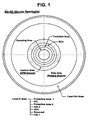
- the BD-RE has, as shown in Fig. 1 , a clamping area, transition area, burst cutting area (BCA) and lead-in area defined sequentially at the inner periphery thereof, and a data area and lead-out area defined respectively at the intermediate portion and outer periphery thereof.
- BCA burst cutting area
- the lead-in area is partitioned into a first protection zone Protection zone 1, a PIC (Permanent Information & Control data) zone, a second protection zone Protection zone 2, an information 2 zone Info 2, an optimum power control (OPC) zone, etc.
- first protection zone and PIC zone are pre-recorded areas where data is pre-recorded in advance
- the remaining zones of the lead-in area, the data area and the lead-out area are rewritable areas where new data is rewritten.
- High frequency modulated (HFM) grooves are formed in the PIC zone, in which main information of the disc to be permanently preserved is stored. These HFM grooves are modulated by a bi-phase modulation method to store disc information (DI), as shown in Fig. 2 .
- DI disc information
- HFM grooves are modulated in the radial direction with a rather high bandwidth signal, to create a data channel for replicated information with sufficient capacity and data rate.
- a bit with value 0 is represented by a transition at the start of the bit cell and a bit with value 1 is represented by a transition at the start and in the middle of the bit cell.
- the modulated bits are recorded on the disc by a deviation of the groove from its average centerline as indicated in Fig. 2 .
- the length of each bit cell shall be 36T, where T corresponds to the length of a channel bit in the rewritable data areas.
- the disc information (DI) contains, as shown in Fig. 3 , channel bit length information with a size of 1 byte, which is detected based on a push-pull signal.
- Four bits b7 to b4 of the channel bit length information are reserved bits having values of '0000', and the remaining four bits b3 to b0 represent the channel bit length of main data such as an A/V stream.
- the remaining four bits b3 to b0 represent that the channel bit length of the main data is 80nm and the recording capacity of the optical disc is 23Gbytes if they are '0000' , that the channel bit length is 74.5nm and the recording capacity is 25Gbytes if they are '0001', and that the channel bit length is 69nm and the recording capacity is 27Gbytes if they are '0010'.
- an optical disc device selects a partial response maximum likelihood (PRML) corresponding to the recording capacity of the BD-RE with reference to the channel bit length information contained in the disc information and performs a bit detection mode appropriate to the selected PRML, so as to normally perform a data playback operation.
- PRML partial response maximum likelihood
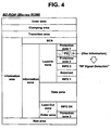
- the new high-density optical disc may be, for example, a BD-ROM, which has, as shown in Fig. 4 , an inner area, clamping area, transition area, information area and rim area.
- the information area includes a BCA, and a PIC zone in which disc information (DI) is recorded.
- DI disc information
- the DI recorded in the straight pit type must be subjected to a decoding process since it is detected in a radio frequency (RF) signal detection mode, not in a push-pull signal detection mode.
- RF radio frequency
- the DI only can be read after full start-up of the drive, it takes a time to start recording or playback of data.
- WO 02/086887 A discloses a high density recording medium comprising a lead-in zone in which a recording medium information is recorded in a straight pit type; and a specific area within said lead-in zone, in which values as disk size, channel bit length and track pitch are recorded.
- the present invention has been made in view of the above problem, and it is an object of the present invention to provide a high-density optical disc wherein a control information recorded on the optical disc, such as channel bit length information, can be detected without a separate decoding operation, or in early stage of drive start-up.
- a control information recorded on the optical disc such as channel bit length information
- a high-density recording medium containing: a lead-in zone in which recording medium information is recorded ; and a specific area, prior to the lead-in zone, in which a control information regarding a recording capacity of the high-density recording medium is recorded, said specific area being a burst cutting area.
- a method for controlling data playback/recording of a high-density recording medium comprising the steps of: a) detecting a control information regarding a channel bit length of the high-density recording medium from a specific area using a push-pull signal detection mode; and b) performing a data playback/recording operation with reference to the detected a control information, said specific area being a burst cutting area.
- a method for controlling data playback of a high-density recording medium comprising the steps of: a) sequentially performing a plurality of predetermined bit detection modes with regard to the recording medium to calculate bit error rates in the bit detection modes, respectively; and b) selecting one of the bit detection modes corresponding to a smallest one of the calculated bit error rates and performing a data playback operation in the selected bit detection mode.
- an apparatus for controlling data playback of a high-density recording medium comprising: a detection unit for performing one of a plurality of predetermined bit detection modes with regard to the high-density recording medium; a decoding unit for calculating and outputting a bit error rate from data bits detected by the detection unit; and a control unit for controlling the bit detection mode of the detection unit and selecting one of the bit detection modes corresponding to a smallest bit error rate on the basis of the calculated bit error rate.
- a high-density optical disc for example, a BD-ROM, to which the present invention is applied has an information area including a BCA, PIC zone, data zone, etc., as stated previously with reference to Fig. 4 .
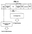
- Disc information is recorded in the PIC zone in a straight pit type, and main data, such as an A/V stream, is recorded in the data zone in the straight pit type.
- the DI, recorded in the straight pit type is detected in an RF signal detection mode, as shown in Fig. 5 .
- playback control information such as channel bit length information set to a different value depending on the recording capacity of the optical disc
- the channel bit length information is additionally recorded in a specific area prior to the PIC zone, for example, the BCA, in a wobble type.
- the channel bit length information may be recorded in the PIC zone in the wobble type. In either case, the channel bit length information, recorded in the wobble type, can be detected in a push-pull signal detection mode without a separate decoding process.
- the channel bit length information can be recorded, as shown in Fig. 6 , with a size of at least 2 bits of the first byte of each data unit recorded in the BCA, as will hereinafter be described in detail.
- the BCA code is based on a structure of maximum 4 data units as shown in Fig. 6 .
- Each data unit contains 16 information bytes I(m,n) and 16 parity bytes C(m,n).
- the code structure contains Sync bytes SB(a,b) and a BCA preamble.
- the first byte I (0,n) of each data unit indicates channel bit length information.
- the minimum channel bit length is 80nm corresponding to a recording capacity of 23Gbytes if bits 'b5 and b4' of the first byte of each data unit are recorded as '00', 74.5nm corresponding to 25Gbytes if they are recorded as '01', and 69nm corresponding to 27Gbytes if they are recorded as '10'.
- Fig. 7 schematically shows the configuration of an optical disc device to which the present invention is applied.
- the optical disc device comprises an optical pickup 11, a video disc play (VDP) system 12, a digital/analog (D/A) converter 13 and so forth. If a BD-ROM 10 is loaded therein, then the optical disc device detects, during initial, servo operation, channel bit length information recorded in the BCA of the BD-ROM 10 in the wobble type using the push-pull signal detection mode without a separate decoding process.
- VDP video disc play
- D/A digital/analog
- the optical disc device determines that the recording capacity of the optical disc is 23Gbytes and the minimum channel bit length of recorded data is 80nm, selects a partial response maximum likelihood (PRML) corresponding to the determination results, and performs a bit detection mode appropriate to the selected PRML.
- PRML partial response maximum likelihood
- the optical disc device determines that the recording capacity of the optical disc is 25Gbytes and the minimum channel bit length of recorded data is 74.5nm, and performs a bit detection mode corresponding to the determination results.
- the optical disc device determines that the recording capacity of the optical disc is 27Gbytes and the minimum channel bit length of recorded data is 69nm, and performs a bit detection mode corresponding to the determination results. As a result, the optical disc device can accurately reproduce DI and main data recorded in the straight pit type.
- the VDP system 12 of the optical disc device checks the recording capacity of the loaded optical disc and selects a bit detection mode most appropriate thereto in order to accurately reproduce DI recorded on the optical disc, more particularly DI recorded in the PIC zone of the disc in the straight pit type, and main data recorded in the data zone of the disc, as will hereinafter be described in detail.
- the VDP system 12 includes, as shown in Fig. 8 , a detector part including a plurality of, for example, first to third equalizers 121, 122 and 123, a first switch 120 for selecting one of the first to third equalizers 121, 122 and 123 and applying an RF input signal to the selected equalizer, a phase locked loop (PLL) circuit 124, a plurality of, for example, first to third PRML detectors 126, 127 and 128, a second switch 125 for selecting one of the first to third PRML detectors 126, 127 and 128 and applying an output signal from the PLL circuit 124 to the selected PRML detector, and an equalizer/PRML selector 132 for controlling the first and second switches 120 and 125.
- PLL phase locked loop
- the VDP system 12 further includes a decoder part including a demodulator 129 for demodulating modulated data of a certain format, an error correcting unit 130 for performing error correction for the demodulated data, and a bit error rate (BER) calculator 131 for calculating a BER of the demodulated data.
- a decoder part including a demodulator 129 for demodulating modulated data of a certain format, an error correcting unit 130 for performing error correction for the demodulated data, and a bit error rate (BER) calculator 131 for calculating a BER of the demodulated data.
- BER bit error rate
- equalizer/PRML selector 132 has been disclosed to be included in the detector part in the present embodiment, it may be included in the decoder part, not in the detector part, or separately configured as a separate part (not shown).
- the PRML Partial Response and Maximum Likelihood
- RF signal Read channel 1 signal
- the PRML typically consists of an equalizer and a Viterbi decoder.
- the equalizer controls inter-symbol interference of Read channel 1 signal (RF signal) and fit Read channel 1 signal to a partial response channel.
- the partial response channel means that the impulse response appears at plural sample points and it is linear time invariant.
- the Viterbi decoder detects binary data using a known correlation of Read channel 1 signal.
- the equalizer/PRML selector 132 in the early stage of the data playback operation, controls the first switch 120 and the second switch 125 such that a first bit detection mode appropriate to an optical disc of 23Gbytes recording capacity is performed.
- a first bit detection mode appropriate to an optical disc of 23Gbytes recording capacity is performed.
- an RF signal read from the BD-ROM 10 is passed along a first path of the first equalizer 121, PLL 124 and first PRML detector 126.
- the BER calculator 131 checks bit data demodulated and error-corrected by the demodulator 129 and error correcting unit 130 to calculate a first BER (BER #1) that is the ratio between normal bit data and erroneous bit data, and then outputs the calculated first BER to the equalizer/PRML selector 132.
- BER #1 bit data demodulated and error-corrected by the demodulator 129 and error correcting unit 130 to calculate a first BER (BER #1) that is the ratio between normal bit data and erroneous bit data
- equalizer/PRML selector 132 selects a path where the smallest amount of bit error occurs, namely, the most appropriate equalizer and PRML detector, on the basis of BER #1,
- BER #2 and BER #3 sequentially calculated through the above process, and controls the first and second switches according to the selected path. Therefore, a bit detection mode optimal to the recording capacity of the optical disc loaded in the device is performed and the data playback operation is thus normally performed.
- the playback control method has been disclosed in association with a read-only optical disc, for example, a BD-ROM, for illustrative purposes, this invention is also applicable to a writable medium, such as a BD-RE or WO, to control a data recording operation.
- a read-only optical disc for example, a BD-ROM
- WO writable medium
- the present invention provides a high-density recording medium and a method and apparatus for controlling data playback thereof, wherein it is possible to perform a data playback operation optimal to the recording capacity of a BD-ROM (Blu-ray Disc-ROM) even through disc information (DI) is recorded in a PIC (Permanent Information & Control data) zone of the BD-ROM in a recording format necessitating a decoding process and the recording capacity is any of different values such as 23Gbytes, 25Gbytes, 27Gbytes, etc.
- BD-ROM Blu-ray Disc-ROM
- PIC Personal Information & Control data
Landscapes
- Optical Recording Or Reproduction (AREA)
- Signal Processing For Digital Recording And Reproducing (AREA)
- Reverberation, Karaoke And Other Acoustics (AREA)
- Pinball Game Machines (AREA)
Claims (29)
- Support d'enregistrement haute densité (10) contenant :une zone de lead-in dans laquelle sont enregistrées des informations du support d'enregistrement ; etune zone spécifique dans laquelle sont enregistrées, selon un type oscillant, des informations de commande concernant une capacité d'enregistrement dudit support d'enregistrement haute densité (10), caractérisé en ce queladite zone spécifique est une zone circulaire centrale d'étiquetage (BCA) située avant, ou au sein de, ladite zone de lead-in.
- Support d'enregistrement haute densité (10) selon la revendication 1, ledit support d'enregistrement étant un BD-ROM (disque ROM Blu-ray) ; BD-WO (disque non réinscriptible Blu-ray) ou BD-RE (disque réinscriptible Blu-ray).
- Support d'enregistrement haute densité (10) selon la revendication 1, dans lequel lesdites informations de commande sont enregistrées au moins dans chaque unité de données de ladite zone circulaire centrale d'étiquetage (BCA).
- Support d'enregistrement haute densité (10) selon la revendication 3, dans lequel lesdites informations de commande sont enregistrées dans un premier octet de ladite unité de données.
- Support d'enregistrement haute densité (10) selon la revendication 1, dans lequel lesdites informations de commande sont des informations de longueur de channel-bits fixées, de manière variable, à une valeur différente en fonction de la capacité d'enregistrement dudit support d'enregistrement haute densité (10).
- Support d'enregistrement haute densité (10) selon la revendication 1, dans lequel une information de commande est enregistrée, selon un type en creux droit, dans ladite zone de lead-in ; et au moins une information de longueur de channel-bit parmi ladite information de commande enregistrée dans ladite zone de lead-in est enregistrée, selon un type oscillant, dans ladite zone circulaire centrale d'étiquetage.
- Support d'enregistrement haute densité (10) selon la revendication 6, dans lequel la zone circulaire centrale d'étiquetage inclut au moins une unité de données, et les informations de longueur de channel-bit sont enregistrées dans ladite au moins une unité de données.
- Support d'enregistrement haute densité (10) selon la revendication 6, dans lequel la zone circulaire centrale d'étiquetage inclut une pluralité d'unités de données, et les informations de longueurs de channel-bit sont enregistrées dans chaque unité de données.
- Support d'enregistrement haute densité (10) selon la revendication 8, dans lequel chaque unité de données contient une pluralité d'octets, et les informations de longueur de channel-bit sont enregistrées dans le premier octet de chaque unité de données.
- Support d'enregistrement haute densité (10) selon la revendication 6, dans lequel les informations de longueur de channel-bit sont fixées de manière variable à une valeur différente dépendant de la capacité d'enregistrement dudit support d'enregistrement.
- Procédé de commande de lecture/d'enregistrement de données depuis/sur un support d'enregistrement haute densité, comprenant les étapes de :a) détection d'une information de commande concernant une capacité d'enregistrement dudit support d'enregistrement haute densité depuis une zone spécifique en utilisant un signal symétrique ; etb) mise en oeuvre d'une opération de lecture/d'enregistrement de données par référence à l'information de commande détectée,caractérisé en ce que ladite zone spécifique est une zone circulaire centrale d'étiquetage (BCA) située avant, ou au sein, de ladite zone de lead-in dudit support d'enregistrement haute densité.
- Procédé selon la revendication 11, dans lequel ladite information de commande est détectée depuis un premier octet de chaque unité de données dans ladite zone circulaire centrale d'étiquetage (BCA).
- Procédé selon la revendication 11, dans lequel ladite information de commande est une information de longueur de channel-bit fixée de manière variable à une valeur différente dépendant de la capacité d'enregistrement dudit support d'enregistrement haute densité.
- Procédé selon la revendication 13, dans lequel ladite étape b) inclut l'étape de mise en oeuvre d'un mode de détection de bit correspondant à la capacité d'enregistrement dudit support d'enregistrement haute densité par référence à ladite information de longueur de channel-bit pour mettre en oeuvre l'opération de lecture/enregistrement de données.
- Procédé selon la revendication 13, dans lequel l'étape de détection a) inclut la détection d'informations de longueur de channel-bit enregistrées, selon un type oscillant, dans une zone circulaire centrale d'étiquetage, l'information de longueur de channel-bit étant également enregistrée, selon un type en creux droit, dans une zone de lead-in, et la zone circulaire centrale d'étiquetage étant située avant la zone de lead-in ; et l'étape de lecture/enregistrement de données b) inclut la commande de l'opération de lecture/enregistrement de données en conformité avec au moins l'information de longueur de channel-bit détectée.
- Procédé selon la revendication 15, dans lequel la zone circulaire centrale d'étiquetage inclut au moins une unité de données, et l'information de longueur de channel-bit est enregistrée dans ladite au moins une unité de données.
- Procédé selon la revendication 15, dans lequel la zone circulaire centrale d'étiquetage inclut une pluralité d'unités de données, et l'information de longueur de channel-bit est enregistrée dans chaque unité de données.
- Procédé selon la revendication 17, dans lequel chaque unité de données contient une pluralité d'octets, et l'information de longueur de channel-bit est enregistrée dans un premier octet de chaque unité de données.
- Procédé selon la revendication 15, dans lequel l'information de longueur de channel-bit est fixée de manière variable à une valeur différente dépendant de la capacité d'enregistrement dudit support d'enregistrement.
- Procédé selon la revendication 15, dans lequel ladite étape b) inclut l'étape de mise en oeuvre d'un mode de détection de bit correspondant à l'information de longueur de channel-bit pour la lecture/l'enregistrement de données.
- Support d'enregistrement haute densité (10) selon la revendication 1, dans lequel la zone circulaire centrale d'étiquetage inclut une ou plusieurs unités de données, chacune desdites unités de données incluant un champ de données ayant huit rangées consécutives, chacune d'un premier groupe de quatre rangées du champ de données incluant un octet de synchronisation et quatre octets d'information, et chacune d'un second groupe de quatre rangées du champ de données incluant un octet de synchronisation et quatre octets de parité.
- Appareil pour commandeur la lecture/l'enregistrement de données sur/depuis un support d'enregistrement haute densité, comprenant un système de lecture de disque (12) configuré pour mettre en oeuvre une opération de lecture/enregistrement de données par référence à l'information de commande détectée,
caractérisé en ce qu'il comprend une tête optique (11) configurée pour détecter une information de commande concernant une capacité d'enregistrement dudit support d'enregistrement haute densité depuis une zone spécifique en utilisant un signal symétrique ; ladite zone spécifique étant une zone circulaire centrale d'étiquetage (BCA) située avant une zone de lead-in dudit support d'enregistrement haute densité. - Appareil selon la revendication 22, dans lequel ladite tête optique détecte ladite information de commande depuis un premier octet de chaque unité de données de ladite zone circulaire centrale d'étiquetage (BCA).
- Appareil selon la revendication 22, dans lequel ladite tête optique est configurée pour détecter des informations de longueur de channel-bit fixées de manière variable à une valeur différente dépendant de la capacité d'enregistrement dudit support d'enregistrement haute densité depuis ladite zone spécifique.
- Appareil selon la revendication 24, dans lequel ledit système de lecture de disque est, en outre, configuré pour mettre en oeuvre un mode de détection de bit correspondant à la capacité d'enregistrement dudit support d'enregistrement haute densité par référence auxdites informations de longueur de channel-bit pour mettre en oeuvre l'opération de lecture/enregistrement de données.
- Appareil selon la revendication 22, dans lequel ladite tête optique est, en outre, configurée pour détecter une information de longueur de channel-bit enregistrée dans une zone circulaire centrale d'étiquetage, l'information de longueur de channel-bit étant également enregistrée dans une zone de lead-in et la zone circulaire centrale d'étiquetage étant située avant la zone de lead-in, et pour commander l'opération de lecture ou d'enregistrement de données en conformité avec au moins l'information de longueur de channel-bit détectée.
- Appareil selon la revendication 26, dans lequel ladite tête optique est configurée pour détecter l'information de longueur de channel-bit depuis au moins une unité de données incluse dans la zone circulaire centrale d'étiquetage.
- Appareil selon la revendication 26,
dans lequel la zone circulaire centrale d'étiquetage inclut une pluralité d'unités de données ; et
dans lequel ladite tête optique est configurée pour détecter l'information de longueur de channel-bit depuis chaque unité de données de la zone circulaire centrale d'étiquetage. - Appareil selon la revendication 28,
dans lequel chaque unité de données contient une pluralité d'octets ; et
dans lequel ladite tête optique est configurée pour détecter l'information de longueur de channel-bit dans un premier octet de chaque unité de données.
Applications Claiming Priority (3)
| Application Number | Priority Date | Filing Date | Title |
|---|---|---|---|
| KR2003012414 | 2003-02-27 | ||
| KR1020030012414A KR100932506B1 (ko) | 2003-02-27 | 2003-02-27 | 고밀도 광디스크의 재생 제어정보 관리 및 데이터 재생제어방법 |
| PCT/KR2004/000422 WO2004077421A1 (fr) | 2003-02-27 | 2004-02-27 | Support d'enregistrement haute densite et appareil pour la commande de lecture de donnees d'un tel support |
Publications (3)
| Publication Number | Publication Date |
|---|---|
| EP1597724A1 EP1597724A1 (fr) | 2005-11-23 |
| EP1597724A4 EP1597724A4 (fr) | 2008-03-26 |
| EP1597724B1 true EP1597724B1 (fr) | 2011-04-27 |
Family
ID=36991142
Family Applications (1)
| Application Number | Title | Priority Date | Filing Date |
|---|---|---|---|
| EP04715572A Expired - Lifetime EP1597724B1 (fr) | 2003-02-27 | 2004-02-27 | Support d'enregistrement haute densite et appareil pour la commande de lecture de donnees d'un tel support |
Country Status (14)
| Country | Link |
|---|---|
| US (2) | US7649819B2 (fr) |
| EP (1) | EP1597724B1 (fr) |
| JP (2) | JP2006519456A (fr) |
| KR (1) | KR100932506B1 (fr) |
| CN (2) | CN101202059B (fr) |
| AT (1) | ATE507559T1 (fr) |
| AU (1) | AU2004210554A1 (fr) |
| BR (1) | BRPI0403925A (fr) |
| CA (1) | CA2505912A1 (fr) |
| DE (1) | DE602004032424D1 (fr) |
| ES (1) | ES2361741T3 (fr) |
| MX (1) | MXPA04010438A (fr) |
| RU (1) | RU2334282C2 (fr) |
| WO (1) | WO2004077421A1 (fr) |
Families Citing this family (12)
| Publication number | Priority date | Publication date | Assignee | Title |
|---|---|---|---|---|
| JP2006048737A (ja) * | 2004-07-30 | 2006-02-16 | Toshiba Corp | 信号処理装置 |
| JP4091606B2 (ja) * | 2005-02-02 | 2008-05-28 | 株式会社東芝 | 光ディスク、光ディスク装置、光ディスク再生方法 |
| JP2007042152A (ja) * | 2005-07-29 | 2007-02-15 | Toshiba Corp | 追記形情報記憶媒体(透明基板上に形成された記録層を内側にして接着された構造を持つ記録形情報記憶媒体のディスク構造)、および情報再生方法または情報記録方法ならびに記憶媒体製造装置 |
| JP4500949B2 (ja) * | 2007-05-11 | 2010-07-14 | 独立行政法人産業技術総合研究所 | 光ディスクの信号処理方法及び装置 |
| WO2009041687A1 (fr) * | 2007-09-27 | 2009-04-02 | Nec Corporation | Dispositif optique de reproduction d'informations |
| AU2008336754A1 (en) * | 2007-12-11 | 2009-06-18 | Panasonic Corporation | Information recording medium and information recording medium evaluation method |
| JP5238436B2 (ja) * | 2008-09-30 | 2013-07-17 | 株式会社日立製作所 | 光ディスク記録装置、光ディスク再生装置、情報記録方法および情報再生方法 |
| JP5241569B2 (ja) | 2009-03-05 | 2013-07-17 | 株式会社日立製作所 | 光ディスク記録装置、光ディスク再生装置、情報記録方法および情報再生方法 |
| TWI397910B (zh) * | 2009-08-24 | 2013-06-01 | Sunplus Technology Co Ltd | 藍光碟片之叢發切割區的抹除資訊標示方法 |
| JP5147879B2 (ja) * | 2010-03-05 | 2013-02-20 | 日立コンシューマエレクトロニクス株式会社 | 光ディスク、光ディスク装置、情報記録方法、および情報再生方法 |
| JP5147880B2 (ja) * | 2010-03-05 | 2013-02-20 | 日立コンシューマエレクトロニクス株式会社 | 光ディスク、光ディスク装置、情報記録方法、および情報再生方法 |
| US9473332B2 (en) * | 2012-04-27 | 2016-10-18 | The Royal Institution For The Advancement Of Learning / Mcgill University | Methods and devices for communications systems using multiplied rate transmission |
Citations (1)
| Publication number | Priority date | Publication date | Assignee | Title |
|---|---|---|---|---|
| WO2002086887A1 (fr) * | 2001-04-24 | 2002-10-31 | Koninklijke Philips Electronics N.V. | Dispositif et procede pour enregistrer des informations |
Family Cites Families (62)
| Publication number | Priority date | Publication date | Assignee | Title |
|---|---|---|---|---|
| JPS61208676A (ja) | 1985-03-13 | 1986-09-17 | Ricoh Co Ltd | デ−タ記録方式 |
| JP2635610B2 (ja) | 1987-09-09 | 1997-07-30 | 株式会社東芝 | ディスク装置 |
| JPH02149932A (ja) | 1988-11-30 | 1990-06-08 | Victor Co Of Japan Ltd | 光ディスク読取装置 |
| US5244705A (en) * | 1990-08-24 | 1993-09-14 | Sony Corporation | Disc-shaped recording medium |
| US5132954A (en) | 1990-09-24 | 1992-07-21 | International Business Machines Corporation | Controls for optical disk relating to accessing and utilization of such disk |
| US5341256A (en) | 1990-11-27 | 1994-08-23 | Matsushita Electric Industrial Co., Ltd. | Rotary head adjuster |
| JPH04283474A (ja) | 1991-03-12 | 1992-10-08 | Sony Corp | デジタルデータ再生装置 |
| US5341356A (en) | 1991-04-02 | 1994-08-23 | U.S. Philips Corporation | Method and device for recording information volumes in a track of a record carrier, and a device for reading the record carrier |
| TW222029B (fr) | 1991-12-18 | 1994-04-01 | Philips Nv | |
| JP3277942B2 (ja) | 1992-03-31 | 2002-04-22 | ソニー株式会社 | 記録媒体の再生装置および記録媒体の記録再生装置 |
| CA2168327C (fr) | 1995-01-30 | 2000-04-11 | Shinichi Kikuchi | Support d'enregistrement de donnees comportant des donnees de navigation, methode et appareil d'enregistrement de telles donnees et systeme de transmission de ces donnees via une route de communication utilisant les donnees de navigation a cette fin |
| JP3456781B2 (ja) | 1995-02-06 | 2003-10-14 | 富士通株式会社 | 磁気記録再生装置の復調回路 |
| US5696756A (en) * | 1995-04-14 | 1997-12-09 | Kabushiki Kaishia Toshiba | Optical disk having an evaluation pattern for evaluating the optical disk |
| DE69614823T2 (de) | 1995-10-09 | 2002-04-11 | Matsushita Electric Industrial Co., Ltd. | Aufzeichnungsgerät für optische platten |
| DE69610861T2 (de) | 1995-10-09 | 2001-03-15 | Matsushita Electric Industrial Co., Ltd. | Optische Scheibe und optisches Wiedergabegerät |
| CN1110799C (zh) | 1996-02-08 | 2003-06-04 | 松下电器产业株式会社 | 光盘,光盘设备和在光盘上再生信息的方法 |
| JPH09282808A (ja) | 1996-04-08 | 1997-10-31 | Sony Corp | データ処理装置およびデータ処理方法 |
| JPH1097765A (ja) * | 1996-07-30 | 1998-04-14 | Toshiba Corp | 記録媒体、その再生装置、データ再生装置及びデータ再生方法 |
| JP3776530B2 (ja) | 1996-09-30 | 2006-05-17 | 株式会社東芝 | 光学的情報再生装置 |
| JP3209126B2 (ja) | 1996-12-20 | 2001-09-17 | 日本ビクター株式会社 | 光記録媒体及び光ディスク再生装置並びに光ディスク再生方法 |
| JP3429972B2 (ja) * | 1997-03-28 | 2003-07-28 | 株式会社日立製作所 | 磁気記録媒体およびそれを用いた磁気記憶装置 |
| JPH10334605A (ja) * | 1997-05-27 | 1998-12-18 | Sony Corp | 情報再生装置および再生方法 |
| JPH10340527A (ja) | 1997-06-05 | 1998-12-22 | Hitachi Ltd | 情報記録装置 |
| JPH1145461A (ja) | 1997-07-23 | 1999-02-16 | Victor Co Of Japan Ltd | ディスク,その識別方法・装置,その再生装置 |
| JP3839926B2 (ja) * | 1997-08-29 | 2006-11-01 | 株式会社東芝 | ディスク再生装置及びディスク再生方法 |
| JP2000078519A (ja) | 1997-09-17 | 2000-03-14 | Matsushita Electric Ind Co Ltd | ビデオデータ編集装置及び編集プログラムを記録したコンピュータ読み取り可能な記録媒体 |
| JPH11102576A (ja) | 1997-09-29 | 1999-04-13 | Toshiba Corp | データ再生装置 |
| KR100255191B1 (ko) | 1997-12-31 | 2000-06-01 | 윤종용 | 광 디스크 재생장치에서 종류 검출을 위한 디스크와그 종류 검출방법 |
| JP2002501655A (ja) * | 1998-03-18 | 2002-01-15 | エスティーマイクロエレクトロニクス エス.アール.エル. | Dvd又はcdサポートから読取ったデータのリード−ソロモンデコーディング |
| JPH11296862A (ja) | 1998-04-15 | 1999-10-29 | Alpine Electronics Inc | ディスク媒体の再生方法 |
| JPH11338956A (ja) | 1998-05-22 | 1999-12-10 | Victor Co Of Japan Ltd | ディスクバーコードデータ再生装置 |
| JP3381627B2 (ja) | 1998-05-29 | 2003-03-04 | 株式会社日立製作所 | ディジタル信号記録方法、及び、ディスク再生方法 |
| US7304937B1 (en) | 1998-06-16 | 2007-12-04 | Thomson Licensing | Identification of program information on a recording medium |
| MXPA01003953A (es) | 1998-10-22 | 2003-03-10 | Matsushita Electric Ind Co Ltd | Medio de grabacion de informacion y metodo y aparato para controlar sus defectos. |
| JP2000132903A (ja) | 1998-10-23 | 2000-05-12 | Texas Instr Japan Ltd | データ誤り訂正装置およびその方法 |
| JP2000149415A (ja) | 1998-11-02 | 2000-05-30 | Matsushita Electric Ind Co Ltd | 光ディスク、光ディスクの再生装置及び複製装置並びに光ディスクの違法使用防止方法 |
| KR100362567B1 (ko) | 1998-12-24 | 2003-04-07 | 삼성전자 주식회사 | 버스트컷팅영역에기록되어있는정보들을디코딩하기위한동기정보검출방법 |
| US6377526B1 (en) | 1999-04-01 | 2002-04-23 | Plasmon Ide, Inc. | Erasable WORM optical disk and method of writing thereto multiple times |
| CN100358034C (zh) | 1999-04-28 | 2007-12-26 | 松下电器产业株式会社 | 光盘记录和再现装置以及光盘记录和再现方法 |
| JP3938449B2 (ja) | 1999-06-02 | 2007-06-27 | パイオニア株式会社 | 光ディスク記録方法、光ディスク記録装置、光ディスク及び光ディスク再生装置 |
| JP3224380B2 (ja) | 1999-07-15 | 2001-10-29 | 松下電器産業株式会社 | 光記録媒体の記録方法 |
| JP2001243636A (ja) | 1999-07-15 | 2001-09-07 | Matsushita Electric Ind Co Ltd | 光記録媒体および光記録媒体の記録方法 |
| NZ516764A (en) | 1999-08-06 | 2003-06-30 | Macrovision Corp | Scaled watermarking technique to prevent bypass of standard watermarks |
| TW561471B (en) * | 2000-01-07 | 2003-11-11 | Matsushita Electric Industrial Co Ltd | Information recording disc and information reproducing system |
| JP2001256655A (ja) | 2000-01-07 | 2001-09-21 | Matsushita Electric Ind Co Ltd | 情報記録ディスク及び情報再生システム |
| KR100694410B1 (ko) | 2000-03-30 | 2007-03-12 | 엘지전자 주식회사 | 다층 광디스크 및 그 구동방법 |
| JP4206620B2 (ja) | 2000-07-31 | 2009-01-14 | 日本ビクター株式会社 | 光情報記録媒体およびその記録再生装置 |
| JP4348851B2 (ja) | 2000-09-21 | 2009-10-21 | ソニー株式会社 | 記録媒体、ディスク記録装置および方法、並びにディスク再生装置及び方法 |
| WO2002025645A2 (fr) * | 2000-09-22 | 2002-03-28 | Matsushita Electric Industrial Co., Ltd. | Disque optique et procede de reproduction, appareil de reproduction, et appareil d'enregistrement associe |
| KR100713097B1 (ko) | 2000-12-26 | 2007-05-02 | 파이오니아 가부시키가이샤 | 정보 기록 매체, 및 정보 재생 장치 및 방법 |
| JP2001229545A (ja) | 2001-01-15 | 2001-08-24 | Victor Co Of Japan Ltd | 光ディスク再生装置 |
| KR100554782B1 (ko) | 2001-03-24 | 2006-02-22 | 엘지전자 주식회사 | 변조 데이터에 동기 데이터를 삽입하는 방법과, 그에 따른기록매체 |
| US20040156294A1 (en) * | 2001-04-17 | 2004-08-12 | Katsuya Watanabe | Optical disc, information recording/reproducing method and information recording/reproducin apparatus using the same |
| US7484231B2 (en) * | 2001-05-14 | 2009-01-27 | Lg Electronics Inc. | High-density disk recording medium having an asymmetrically-shaped center hole and manufacturing method thereof |
| KR100582955B1 (ko) | 2001-05-14 | 2006-05-23 | 엘지전자 주식회사 | 비대칭 상하구조의 중앙홀을 갖는 고밀도 광디스크 및 그 제조방법 |
| JP2003006997A (ja) * | 2001-06-21 | 2003-01-10 | Sony Corp | 光ディスク、光ディスク製造方法、ディスクドライブ方法、ディスクドライブ装置 |
| JP2003030856A (ja) | 2001-07-17 | 2003-01-31 | Pioneer Electronic Corp | 光ディスク並びに記録及び再生装置 |
| JP2003036543A (ja) * | 2001-07-24 | 2003-02-07 | Pioneer Electronic Corp | 記録ディスク及び記録情報再生装置 |
| KR100677104B1 (ko) | 2002-05-20 | 2007-02-01 | 삼성전자주식회사 | 소거 패턴의 파워 정보가 저장된 광 기록 매체 |
| ATE485584T1 (de) * | 2002-08-22 | 2010-11-15 | Lg Electronics Inc | Hochdichter optischer datenträger und aufnahme- /wiedergabe verfahren dafür |
| JP2003196843A (ja) | 2002-10-17 | 2003-07-11 | Victor Co Of Japan Ltd | 光記録媒体 |
| TWI366190B (en) * | 2003-01-23 | 2012-06-11 | Lg Electronics Inc | Recording medium with an intermittent or alternate wobbled pits and apparatus and methods for forming, recording, and reproducing the recording medium |
-
2003
- 2003-02-27 KR KR1020030012414A patent/KR100932506B1/ko not_active Expired - Fee Related
-
2004
- 2004-02-27 MX MXPA04010438A patent/MXPA04010438A/es active IP Right Grant
- 2004-02-27 RU RU2004137479/28A patent/RU2334282C2/ru active
- 2004-02-27 DE DE602004032424T patent/DE602004032424D1/de not_active Expired - Lifetime
- 2004-02-27 JP JP2006502723A patent/JP2006519456A/ja active Pending
- 2004-02-27 CN CN200710167161XA patent/CN101202059B/zh not_active Expired - Fee Related
- 2004-02-27 CN CNB2004800001526A patent/CN100468533C/zh not_active Expired - Lifetime
- 2004-02-27 EP EP04715572A patent/EP1597724B1/fr not_active Expired - Lifetime
- 2004-02-27 AU AU2004210554A patent/AU2004210554A1/en not_active Abandoned
- 2004-02-27 US US10/787,159 patent/US7649819B2/en not_active Expired - Fee Related
- 2004-02-27 WO PCT/KR2004/000422 patent/WO2004077421A1/fr not_active Ceased
- 2004-02-27 ES ES04715572T patent/ES2361741T3/es not_active Expired - Lifetime
- 2004-02-27 BR BR0403925-4A patent/BRPI0403925A/pt not_active Application Discontinuation
- 2004-02-27 AT AT04715572T patent/ATE507559T1/de not_active IP Right Cessation
- 2004-02-27 CA CA002505912A patent/CA2505912A1/fr not_active Abandoned
-
2008
- 2008-08-28 JP JP2008220318A patent/JP2009004090A/ja active Pending
-
2009
- 2009-11-17 US US12/591,339 patent/US7978582B2/en not_active Expired - Lifetime
Patent Citations (1)
| Publication number | Priority date | Publication date | Assignee | Title |
|---|---|---|---|---|
| WO2002086887A1 (fr) * | 2001-04-24 | 2002-10-31 | Koninklijke Philips Electronics N.V. | Dispositif et procede pour enregistrer des informations |
Also Published As
| Publication number | Publication date |
|---|---|
| CN100468533C (zh) | 2009-03-11 |
| EP1597724A4 (fr) | 2008-03-26 |
| KR20040077034A (ko) | 2004-09-04 |
| CN101202059A (zh) | 2008-06-18 |
| JP2009004090A (ja) | 2009-01-08 |
| BRPI0403925A (pt) | 2005-01-04 |
| US7978582B2 (en) | 2011-07-12 |
| CA2505912A1 (fr) | 2004-09-10 |
| RU2334282C2 (ru) | 2008-09-20 |
| RU2004137479A (ru) | 2006-08-20 |
| MXPA04010438A (es) | 2005-04-22 |
| EP1597724A1 (fr) | 2005-11-23 |
| DE602004032424D1 (de) | 2011-06-09 |
| ES2361741T3 (es) | 2011-06-21 |
| JP2006519456A (ja) | 2006-08-24 |
| US7649819B2 (en) | 2010-01-19 |
| CN1698100A (zh) | 2005-11-16 |
| AU2004210554A1 (en) | 2004-09-10 |
| CN101202059B (zh) | 2012-05-30 |
| ATE507559T1 (de) | 2011-05-15 |
| US20040228244A1 (en) | 2004-11-18 |
| KR100932506B1 (ko) | 2009-12-17 |
| US20100067359A1 (en) | 2010-03-18 |
| WO2004077421A1 (fr) | 2004-09-10 |
Similar Documents
| Publication | Publication Date | Title |
|---|---|---|
| US7978582B2 (en) | High-density recording medium and method and apparatus for controlling data playback thereof | |
| US8331209B2 (en) | High-density optical disc and recording/reproducing method thereof | |
| JP4571660B2 (ja) | 選択的情報を有する記録媒体と、その記録媒体にデータを形成し、記録し、再生するための装置及び方法と、再生を制御するための装置及び方法 | |
| JP2005524192A (ja) | 高密度再生専用光ディスクとそれによる光ディスク装置及び方法 | |
| EP1519379B1 (fr) | Support d'enregistrement optique, dispositif de traitement de donnees utilisant ce support d'enregistrement et procede d'enregistrement de donnees | |
| CN101578662B (zh) | 光盘、光盘记录再生方法 | |
| JP2006127679A (ja) | 光ディスク装置及び光ディスク再生方法 | |
| WO2001099108A1 (fr) | Unite de disque optique | |
| KR20060042900A (ko) | 기록 매체 평가 방법, 기록 재생 장치, 및 기록 매체 | |
| US7656760B2 (en) | Playback apparatus and sync signal detecting method | |
| JP2001167510A (ja) | 光ディスク判別方法及び光ディスク装置 | |
| JP2005536002A (ja) | 高密度光ディスク、高密度光ディスクへのアドレスまたは/及びサーボ情報記録方法、高密度光ディスクに記録されたデータの再生方法 | |
| AU2008200289B2 (en) | High-density recording medium and method and apparatus for controlling data playback/recording thereof | |
| KR20030085754A (ko) | 고밀도 재생전용 광디스크와, 그에 따른 광디스크 장치 및방법 | |
| KR100295476B1 (ko) | 기록매체,그재생장치,데이타재생장치및데이타재생방법 | |
| JP2002150564A (ja) | 円盤状記録媒体の復号装置 | |
| KR100938393B1 (ko) | 고밀도 재생전용 광디스크와, 그에 따른 광디스크 장치 및방법 | |
| JP3761036B2 (ja) | 記録媒体再生装置および記録媒体再生方法並びに光ディスク | |
| JP2002124040A (ja) | 光ディスク、光ディスク判別方法及び光ディスク装置 | |
| JP2005149670A (ja) | 情報記録再生装置 |
Legal Events
| Date | Code | Title | Description |
|---|---|---|---|
| PUAI | Public reference made under article 153(3) epc to a published international application that has entered the european phase |
Free format text: ORIGINAL CODE: 0009012 |
|
| 17P | Request for examination filed |
Effective date: 20050913 |
|
| AK | Designated contracting states |
Kind code of ref document: A1 Designated state(s): AT BE BG CH CY CZ DE DK EE ES FI FR GB GR HU IE IT LI LU MC NL PT RO SE SI SK TR |
|
| AX | Request for extension of the european patent |
Extension state: AL LT LV MK |
|
| DAX | Request for extension of the european patent (deleted) | ||
| A4 | Supplementary search report drawn up and despatched |
Effective date: 20080227 |
|
| 17Q | First examination report despatched |
Effective date: 20080704 |
|
| GRAP | Despatch of communication of intention to grant a patent |
Free format text: ORIGINAL CODE: EPIDOSNIGR1 |
|
| GRAJ | Information related to disapproval of communication of intention to grant by the applicant or resumption of examination proceedings by the epo deleted |
Free format text: ORIGINAL CODE: EPIDOSDIGR1 |
|
| GRAP | Despatch of communication of intention to grant a patent |
Free format text: ORIGINAL CODE: EPIDOSNIGR1 |
|
| GRAC | Information related to communication of intention to grant a patent modified |
Free format text: ORIGINAL CODE: EPIDOSCIGR1 |
|
| GRAS | Grant fee paid |
Free format text: ORIGINAL CODE: EPIDOSNIGR3 |
|
| GRAA | (expected) grant |
Free format text: ORIGINAL CODE: 0009210 |
|
| AK | Designated contracting states |
Kind code of ref document: B1 Designated state(s): AT BE BG CH CY CZ DE DK EE ES FI FR GB GR HU IE IT LI LU MC NL PT RO SE SI SK TR |
|
| REG | Reference to a national code |
Ref country code: GB Ref legal event code: FG4D |
|
| REG | Reference to a national code |
Ref country code: CH Ref legal event code: EP |
|
| REG | Reference to a national code |
Ref country code: IE Ref legal event code: FG4D |
|
| REF | Corresponds to: |
Ref document number: 602004032424 Country of ref document: DE Date of ref document: 20110609 Kind code of ref document: P |
|
| REG | Reference to a national code |
Ref country code: DE Ref legal event code: R096 Ref document number: 602004032424 Country of ref document: DE Effective date: 20110609 |
|
| REG | Reference to a national code |
Ref country code: ES Ref legal event code: FG2A Ref document number: 2361741 Country of ref document: ES Kind code of ref document: T3 Effective date: 20110621 |
|
| REG | Reference to a national code |
Ref country code: NL Ref legal event code: T3 |
|
| PG25 | Lapsed in a contracting state [announced via postgrant information from national office to epo] |
Ref country code: SE Free format text: LAPSE BECAUSE OF FAILURE TO SUBMIT A TRANSLATION OF THE DESCRIPTION OR TO PAY THE FEE WITHIN THE PRESCRIBED TIME-LIMIT Effective date: 20110427 Ref country code: PT Free format text: LAPSE BECAUSE OF FAILURE TO SUBMIT A TRANSLATION OF THE DESCRIPTION OR TO PAY THE FEE WITHIN THE PRESCRIBED TIME-LIMIT Effective date: 20110829 |
|
| PG25 | Lapsed in a contracting state [announced via postgrant information from national office to epo] |
Ref country code: GR Free format text: LAPSE BECAUSE OF FAILURE TO SUBMIT A TRANSLATION OF THE DESCRIPTION OR TO PAY THE FEE WITHIN THE PRESCRIBED TIME-LIMIT Effective date: 20110728 Ref country code: FI Free format text: LAPSE BECAUSE OF FAILURE TO SUBMIT A TRANSLATION OF THE DESCRIPTION OR TO PAY THE FEE WITHIN THE PRESCRIBED TIME-LIMIT Effective date: 20110427 Ref country code: BE Free format text: LAPSE BECAUSE OF FAILURE TO SUBMIT A TRANSLATION OF THE DESCRIPTION OR TO PAY THE FEE WITHIN THE PRESCRIBED TIME-LIMIT Effective date: 20110427 Ref country code: CY Free format text: LAPSE BECAUSE OF FAILURE TO SUBMIT A TRANSLATION OF THE DESCRIPTION OR TO PAY THE FEE WITHIN THE PRESCRIBED TIME-LIMIT Effective date: 20110427 Ref country code: AT Free format text: LAPSE BECAUSE OF FAILURE TO SUBMIT A TRANSLATION OF THE DESCRIPTION OR TO PAY THE FEE WITHIN THE PRESCRIBED TIME-LIMIT Effective date: 20110427 Ref country code: SI Free format text: LAPSE BECAUSE OF FAILURE TO SUBMIT A TRANSLATION OF THE DESCRIPTION OR TO PAY THE FEE WITHIN THE PRESCRIBED TIME-LIMIT Effective date: 20110427 |
|
| PG25 | Lapsed in a contracting state [announced via postgrant information from national office to epo] |
Ref country code: CZ Free format text: LAPSE BECAUSE OF FAILURE TO SUBMIT A TRANSLATION OF THE DESCRIPTION OR TO PAY THE FEE WITHIN THE PRESCRIBED TIME-LIMIT Effective date: 20110427 Ref country code: EE Free format text: LAPSE BECAUSE OF FAILURE TO SUBMIT A TRANSLATION OF THE DESCRIPTION OR TO PAY THE FEE WITHIN THE PRESCRIBED TIME-LIMIT Effective date: 20110427 |
|
| PG25 | Lapsed in a contracting state [announced via postgrant information from national office to epo] |
Ref country code: RO Free format text: LAPSE BECAUSE OF FAILURE TO SUBMIT A TRANSLATION OF THE DESCRIPTION OR TO PAY THE FEE WITHIN THE PRESCRIBED TIME-LIMIT Effective date: 20110427 Ref country code: DK Free format text: LAPSE BECAUSE OF FAILURE TO SUBMIT A TRANSLATION OF THE DESCRIPTION OR TO PAY THE FEE WITHIN THE PRESCRIBED TIME-LIMIT Effective date: 20110427 Ref country code: SK Free format text: LAPSE BECAUSE OF FAILURE TO SUBMIT A TRANSLATION OF THE DESCRIPTION OR TO PAY THE FEE WITHIN THE PRESCRIBED TIME-LIMIT Effective date: 20110427 |
|
| PLBE | No opposition filed within time limit |
Free format text: ORIGINAL CODE: 0009261 |
|
| STAA | Information on the status of an ep patent application or granted ep patent |
Free format text: STATUS: NO OPPOSITION FILED WITHIN TIME LIMIT |
|
| 26N | No opposition filed |
Effective date: 20120130 |
|
| REG | Reference to a national code |
Ref country code: DE Ref legal event code: R097 Ref document number: 602004032424 Country of ref document: DE Effective date: 20120130 |
|
| PG25 | Lapsed in a contracting state [announced via postgrant information from national office to epo] |
Ref country code: MC Free format text: LAPSE BECAUSE OF NON-PAYMENT OF DUE FEES Effective date: 20120229 |
|
| REG | Reference to a national code |
Ref country code: CH Ref legal event code: PL |
|
| PG25 | Lapsed in a contracting state [announced via postgrant information from national office to epo] |
Ref country code: LI Free format text: LAPSE BECAUSE OF NON-PAYMENT OF DUE FEES Effective date: 20120229 Ref country code: CH Free format text: LAPSE BECAUSE OF NON-PAYMENT OF DUE FEES Effective date: 20120229 |
|
| REG | Reference to a national code |
Ref country code: IE Ref legal event code: MM4A |
|
| PG25 | Lapsed in a contracting state [announced via postgrant information from national office to epo] |
Ref country code: IE Free format text: LAPSE BECAUSE OF NON-PAYMENT OF DUE FEES Effective date: 20120227 |
|
| PG25 | Lapsed in a contracting state [announced via postgrant information from national office to epo] |
Ref country code: BG Free format text: LAPSE BECAUSE OF FAILURE TO SUBMIT A TRANSLATION OF THE DESCRIPTION OR TO PAY THE FEE WITHIN THE PRESCRIBED TIME-LIMIT Effective date: 20110727 |
|
| PG25 | Lapsed in a contracting state [announced via postgrant information from national office to epo] |
Ref country code: TR Free format text: LAPSE BECAUSE OF FAILURE TO SUBMIT A TRANSLATION OF THE DESCRIPTION OR TO PAY THE FEE WITHIN THE PRESCRIBED TIME-LIMIT Effective date: 20110427 |
|
| PG25 | Lapsed in a contracting state [announced via postgrant information from national office to epo] |
Ref country code: LU Free format text: LAPSE BECAUSE OF NON-PAYMENT OF DUE FEES Effective date: 20120227 |
|
| PG25 | Lapsed in a contracting state [announced via postgrant information from national office to epo] |
Ref country code: HU Free format text: LAPSE BECAUSE OF FAILURE TO SUBMIT A TRANSLATION OF THE DESCRIPTION OR TO PAY THE FEE WITHIN THE PRESCRIBED TIME-LIMIT Effective date: 20040227 |
|
| REG | Reference to a national code |
Ref country code: FR Ref legal event code: PLFP Year of fee payment: 13 |
|
| REG | Reference to a national code |
Ref country code: FR Ref legal event code: PLFP Year of fee payment: 14 |
|
| REG | Reference to a national code |
Ref country code: FR Ref legal event code: PLFP Year of fee payment: 15 |
|
| PGFP | Annual fee paid to national office [announced via postgrant information from national office to epo] |
Ref country code: FR Payment date: 20230105 Year of fee payment: 20 Ref country code: ES Payment date: 20230316 Year of fee payment: 20 |
|
| PGFP | Annual fee paid to national office [announced via postgrant information from national office to epo] |
Ref country code: IT Payment date: 20230109 Year of fee payment: 20 Ref country code: GB Payment date: 20230105 Year of fee payment: 20 Ref country code: DE Payment date: 20230105 Year of fee payment: 20 |
|
| P01 | Opt-out of the competence of the unified patent court (upc) registered |
Effective date: 20230524 |
|
| PGFP | Annual fee paid to national office [announced via postgrant information from national office to epo] |
Ref country code: NL Payment date: 20230106 Year of fee payment: 20 |
|
| REG | Reference to a national code |
Ref country code: DE Ref legal event code: R071 Ref document number: 602004032424 Country of ref document: DE |
|
| REG | Reference to a national code |
Ref country code: NL Ref legal event code: MK Effective date: 20240226 |
|
| REG | Reference to a national code |
Ref country code: ES Ref legal event code: FD2A Effective date: 20240305 |
|
| REG | Reference to a national code |
Ref country code: GB Ref legal event code: PE20 Expiry date: 20240226 |
|
| PG25 | Lapsed in a contracting state [announced via postgrant information from national office to epo] |
Ref country code: ES Free format text: LAPSE BECAUSE OF EXPIRATION OF PROTECTION Effective date: 20240228 |
|
| PG25 | Lapsed in a contracting state [announced via postgrant information from national office to epo] |
Ref country code: ES Free format text: LAPSE BECAUSE OF EXPIRATION OF PROTECTION Effective date: 20240228 Ref country code: GB Free format text: LAPSE BECAUSE OF EXPIRATION OF PROTECTION Effective date: 20240226 |