EP1648686B2 - Verfahren und vorrichtung zum selektiven sintern von teilchenmaterial - Google Patents
Verfahren und vorrichtung zum selektiven sintern von teilchenmaterial Download PDFInfo
- Publication number
- EP1648686B2 EP1648686B2 EP04743477.4A EP04743477A EP1648686B2 EP 1648686 B2 EP1648686 B2 EP 1648686B2 EP 04743477 A EP04743477 A EP 04743477A EP 1648686 B2 EP1648686 B2 EP 1648686B2
- Authority
- EP
- European Patent Office
- Prior art keywords
- radiation
- layer
- particulate material
- area
- absorption
- Prior art date
- Legal status (The legal status is an assumption and is not a legal conclusion. Google has not performed a legal analysis and makes no representation as to the accuracy of the status listed.)
- Expired - Lifetime
Links
Images


Classifications
-
- B—PERFORMING OPERATIONS; TRANSPORTING
- B29—WORKING OF PLASTICS; WORKING OF SUBSTANCES IN A PLASTIC STATE IN GENERAL
- B29C—SHAPING OR JOINING OF PLASTICS; SHAPING OF MATERIAL IN A PLASTIC STATE, NOT OTHERWISE PROVIDED FOR; AFTER-TREATMENT OF THE SHAPED PRODUCTS, e.g. REPAIRING
- B29C67/00—Shaping techniques not covered by groups B29C39/00 - B29C65/00, B29C70/00 or B29C73/00
- B29C67/02—Moulding by agglomerating
- B29C67/04—Sintering
-
- B—PERFORMING OPERATIONS; TRANSPORTING
- B29—WORKING OF PLASTICS; WORKING OF SUBSTANCES IN A PLASTIC STATE IN GENERAL
- B29C—SHAPING OR JOINING OF PLASTICS; SHAPING OF MATERIAL IN A PLASTIC STATE, NOT OTHERWISE PROVIDED FOR; AFTER-TREATMENT OF THE SHAPED PRODUCTS, e.g. REPAIRING
- B29C64/00—Additive manufacturing, i.e. manufacturing of three-dimensional [3D] objects by additive deposition, additive agglomeration or additive layering, e.g. by 3D printing, stereolithography or selective laser sintering
- B29C64/10—Processes of additive manufacturing
- B29C64/141—Processes of additive manufacturing using only solid materials
- B29C64/153—Processes of additive manufacturing using only solid materials using layers of powder being selectively joined, e.g. by selective laser sintering or melting
-
- B—PERFORMING OPERATIONS; TRANSPORTING
- B29—WORKING OF PLASTICS; WORKING OF SUBSTANCES IN A PLASTIC STATE IN GENERAL
- B29C—SHAPING OR JOINING OF PLASTICS; SHAPING OF MATERIAL IN A PLASTIC STATE, NOT OTHERWISE PROVIDED FOR; AFTER-TREATMENT OF THE SHAPED PRODUCTS, e.g. REPAIRING
- B29C67/00—Shaping techniques not covered by groups B29C39/00 - B29C65/00, B29C70/00 or B29C73/00
- B29C67/02—Moulding by agglomerating
-
- B—PERFORMING OPERATIONS; TRANSPORTING
- B29—WORKING OF PLASTICS; WORKING OF SUBSTANCES IN A PLASTIC STATE IN GENERAL
- B29C—SHAPING OR JOINING OF PLASTICS; SHAPING OF MATERIAL IN A PLASTIC STATE, NOT OTHERWISE PROVIDED FOR; AFTER-TREATMENT OF THE SHAPED PRODUCTS, e.g. REPAIRING
- B29C35/00—Heating, cooling or curing, e.g. crosslinking or vulcanising; Apparatus therefor
- B29C35/02—Heating or curing, e.g. crosslinking or vulcanizing during moulding, e.g. in a mould
- B29C35/0288—Controlling heating or curing of polymers during moulding, e.g. by measuring temperatures or properties of the polymer and regulating the process
-
- B—PERFORMING OPERATIONS; TRANSPORTING
- B29—WORKING OF PLASTICS; WORKING OF SUBSTANCES IN A PLASTIC STATE IN GENERAL
- B29K—INDEXING SCHEME ASSOCIATED WITH SUBCLASSES B29B, B29C OR B29D, RELATING TO MOULDING MATERIALS OR TO MATERIALS FOR MOULDS, REINFORCEMENTS, FILLERS OR PREFORMED PARTS, e.g. INSERTS
- B29K2105/00—Condition, form or state of moulded material or of the material to be shaped
- B29K2105/0005—Condition, form or state of moulded material or of the material to be shaped containing compounding ingredients
- B29K2105/0047—Agents changing thermal characteristics
- B29K2105/005—Heat sensitisers or absorbers
-
- B—PERFORMING OPERATIONS; TRANSPORTING
- B29—WORKING OF PLASTICS; WORKING OF SUBSTANCES IN A PLASTIC STATE IN GENERAL
- B29K—INDEXING SCHEME ASSOCIATED WITH SUBCLASSES B29B, B29C OR B29D, RELATING TO MOULDING MATERIALS OR TO MATERIALS FOR MOULDS, REINFORCEMENTS, FILLERS OR PREFORMED PARTS, e.g. INSERTS
- B29K2105/00—Condition, form or state of moulded material or of the material to be shaped
- B29K2105/06—Condition, form or state of moulded material or of the material to be shaped containing reinforcements, fillers or inserts
- B29K2105/16—Fillers
-
- B—PERFORMING OPERATIONS; TRANSPORTING
- B29—WORKING OF PLASTICS; WORKING OF SUBSTANCES IN A PLASTIC STATE IN GENERAL
- B29K—INDEXING SCHEME ASSOCIATED WITH SUBCLASSES B29B, B29C OR B29D, RELATING TO MOULDING MATERIALS OR TO MATERIALS FOR MOULDS, REINFORCEMENTS, FILLERS OR PREFORMED PARTS, e.g. INSERTS
- B29K2995/00—Properties of moulding materials, reinforcements, fillers, preformed parts or moulds
- B29K2995/0018—Properties of moulding materials, reinforcements, fillers, preformed parts or moulds having particular optical properties, e.g. fluorescent or phosphorescent
- B29K2995/003—Reflective
-
- B—PERFORMING OPERATIONS; TRANSPORTING
- B33—ADDITIVE MANUFACTURING TECHNOLOGY
- B33Y—ADDITIVE MANUFACTURING, i.e. MANUFACTURING OF THREE-DIMENSIONAL [3D] OBJECTS BY ADDITIVE DEPOSITION, ADDITIVE AGGLOMERATION OR ADDITIVE LAYERING, e.g. BY 3D PRINTING, STEREOLITHOGRAPHY OR SELECTIVE LASER SINTERING
- B33Y10/00—Processes of additive manufacturing
Definitions
- Embodiments of the present invention relate to a method of selectively combining particulate material and/or apparatus for combining particulate material.
- Rapid Prototyping is widely used to form prototype components, and a number of methods are currently available for carrying out rapid prototyping.
- a computer generated three dimensional model of the component is initially produced using computer assisted drawing (CAD) software.
- CAD computer assisted drawing
- the three dimensional model is then sliced into a number of virtual layers, and a device used to form and combine the layers to create the three dimensional component.
- D1 discloses a process of making a three-dimensional object that includes providing a layer of powder material and selectively depositing bonding inhibitor on selected areas of the layer of powder material. The areas to be deposited with the bonding inhibitor are selected according to a cross-section design of the three-dimensional object. The process also includes promoting bonding of the uninhibited areas of the entire layer of powder material by either sintering or bulk deposition of chemical binders. The process further includes repeating the steps of providing a layer of powder material, selectively depositing bonding inhibitor and promoting bonding until the three-dimensional object is formed.
- D2 discloses a method for the manufacturing of parts, especially molds or cores, by a deposition technique, comprising the steps of: depositing a layer of a pourable composite material containing particles with a binder material coating, into a process area of a defined length and width fitting to the dimensions of a part to be manufactured; applying a moderating agent onto said composite material layer in a selective sub-area of said process area; inducing energy to solidify said selective sub-area, respectively the area of said process area void of said moderating agent; repeating the aforementioned steps; and separating of solidified composite material from non-solidified composite material.
- the Features of the preamble of claim 14 are known from this document.
- the surface portion that receives variable radiation absorption may be a part, and not the whole, of the surface of the layer of particulate material.
- variable radiation absorption across the surface portion may require the existence of multiple areas in which the absorption of radiation is different and greater than zero.
- variable radiation absorption across the surface portion may be provided by varying the intensity of the provided radiation incident on the surface portion of the layer of particulate material.
- variable radiation absorption across the surface portion may be provided by varying the absorptive properties of the particulate material across the selected surface portion of the layer.
- apparatus for combining particulate material for example plastics material by sintering
- the apparatus comprising a controller C for enabling the exposure of a surface portion of a layer 10 of particulate material to radiation, for example infra-red radiation provided by a radiation source 12, the controller C being arranged to control the variation of radiation absorption across the surface portion.
- radiation for example infra-red radiation provided by a radiation source 12
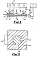
- Fig. 1 illustrates an apparatus, not claimed, for sintering particulate material in which an obscurer 14 (i.e. a mask) is provided for selectively obscuring the radiation provided by the source 12 on the surface portion of the layer 10 to thereby vary the intensity of the radiation incident on the surface portion of the layer 10.
- the obscurer 14 comprises a radiation transmissive substrate 16, such as a glass plate, which carries a varying amount of radiation reflective material 18, such as aluminium oxide.
- the amount and pattern of material 18 deposited on the substrate may be varied to selectively vary the intensity of radiation incident on the surface portion of the layer 10, as will be described hereinafter.
- the surface portion of the layer 10 is logically divided by the obscurer 14 into a number of areas including a combination portion 20, which is to be exposed to radiation to combine the particulate material, and a non-combination portion 22 which is to be shielded, or at least substantially shielded, from radiation to prevent combination of the particulate material by sintering.
- Full shielding of the non-combination portion 22 is not essential, provided that the intensity of radiation transmitted to the non-combination portion 22 is such that the particulate material is not heated to its sintering temperature. In some circumstances, transmission of low intensity radiation onto the non-combination portion 22 to heat the material can be desirable and can result in improved accuracy of the finished component. This is because heating material in the non-combination portion 22 reduces the thermal gradient between the material in the combination portion 20 and the non-combination portion 22.
- the combination portion 20 is logically divided by the obscurer 14 into a central portion 24 and an edge portion 26, and reflective material 18 is deposited onto the substrate 16 such that a greater amount of the material 18 is provided on the central portion 24 than on the edge portion 26 where no reflective material 18 may be provided. Consequently, the intensity of radiation provided across the surface of the combination portion 20 increases from a minimum value at the central portion 24 to a maximum value at the edge portion 26 where the surface of the layer 10 of particulate material is fully exposed to radiation provided by the radiation source 12.
- the layer of reflective material is schematically illustrated in Fig. 1 .
- the variation of thickness of the layer in the figure does not illustrate a variation of thickness of the layer in practice but illustrates a variation in the amount of the material. Where the layer is thick in the figure, in practice there will be a large amount of the material present.
- combination portion 20 has been shown to have only one edge portion 26 such that the central portion 24 is located at the centre of the combination portion 20, it should be appreciated that the combination portion 20 may for example be of annular configuration such that the central portion 24 is bounded on two sides by edge portions 26. Moreover, it is not essential that the central portion 24 is located at the centre of the surface portion of the layer 10 of particulate material.
- the controller C is arranged to control a motor 28 for moving the obscurer 16 from an obscuring position in which it overlies the layer 10, as shown in Fig. 1 , to a non-obscuring position in which it does not overly the layer 10.
- the controller C is also arranged to control a deposition device, such as a printing head 30, for depositing the reflective material 18 onto the substrate 16.
- the controller C controls the amount of material 18 deposited by the head 30 onto each part of the substrate 16.
- the head 30 remains stationary and deposits reflective material 18 onto the substrate 16 as the motor 28 moves the substrate 16 past the head 30.
- the substrate 16 may remain stationary, overlying the layer 10, and the motor 28 may move the printing head 30 over the substrate 16 to deposit reflective material 18 thereon.
- the reflective material 18 is contemporaneously printed onto the substrate 16 during operation of the apparatus.
- the amount of material 18 printed onto the substrate 16 by the head 30 may be varied by the controller C according to the surface temperature of the layer 10.
- the surface temperature of the layer 10 may be measured by a temperature measuring device, such as, for example, a pyrometer P or a thermal imaging camera, and surface temperature measurements are communicated in real time to the controller C.
- a wiping arrangement (not shown) may be provided for removing reflective material 18 from the substrate 16, so that it can be re-used. Different amounts of material 18 can be deposited onto the substrate 16, in dependence on the desired radiation intensity profile at the substrate surface.
- the reflective material 18 may be pre-printed onto the substrate 16 prior to operation of the apparatus and the same pre-printed substrate 16, or a number of pre-printed substrates 16, may be used, one for each layer 10 of particulate material. In this case, measurement of the surface temperature using pyrometer P may not be needed.
- the use of a plurality of pre-printed substrates 16 is particularly advantageous when there is a need to produce a large quantity of the same component since it reduces the time taken to sinter each layer of material and hence produce the prototype component, increases repeatability and leads to a reduction in the cost of producing the components.
- the apparatus may be operable to utilise a plurality of pre-printed substrates 16, or to contemporaneously print different amounts of reflective material 18 onto the same substrate 16, and to use these to expose the same layer 10 of material to different radiation intensity profiles in multiple exposure steps.
- Fig. 3 illustrates an apparatus, not claimed, for combining particulate material, in which corresponding elements are given corresponding reference numerals.
- the apparatus of Fig. 3 is similar to that shown in Fig. 1 , except that instead of the reflective material 18 being deposited onto a substrate 16, the reflective material 18 is deposited, using the printing head 30, directly onto the surface portion of the layer 10 of particulate material.
- the printing head 30 is again controlled by the controller C which controls both the movement of the head 30 across the surface of the layer 10 and the rate of deposition of reflective material 18 onto the layer 10.
- real time measurement of the surface temperature of the layer 10 may be carried out using a temperature measurement device, for example, a pyrometer P or thermal imaging camera, the temperature measurement being used by the controller C to determine the amount of reflective material 18 to be printed by the head 30 onto the surface portion of the layer 10.
- the layer of reflective material is schematically illustrated in Fig. 3 .
- the variation of thickness of the layer in the figure does not illustrate a variation of thickness of the layer in practice but illustrates a variation in the amount of the material. Where the layer is thick in the figure, in practice there will be a large amount of the material present.
- Fig. 4 illustrates an apparatus, not claimed, for combining particulate material which is similar to the apparatus illustrated in Figs. 1 and 3 and in which corresponding elements are given corresponding reference numerals.
- the controller C is arranged to selectively redirect the radiation provided by the source 12 and thereby vary the radiation intensity incident across the surface portion of the layer 10. Selective redirection of the radiation is achieved by controlling, using the controller C, a plurality of mirrors 34 which form a Digital Mirror Device (DMD) 36.
- DMD Digital Mirror Device
- Each mirror 34 is adjustable by the controller to an operative position, in which radiation is fully redirected onto the surface portion of the layer 10, or to an inoperative position in which radiation is fully redirected away from the surface portion.
- the surface portion of the layer 10 can be effectively divided into an array of segments, as discussed hereinafter, and the intensity of the radiation incident on each segment can be varied, according to a bitmap image, by selectively varying the frequencies at which individual mirrors 34 are moved between the operative and inoperative positions.
- a temperature measurement device such as a pyrometer P
- the controller C in response to instantaneous temperature variations across the surface portion of the layer 10.
- Fig. 5 illustrates an apparatus according to various embodiments of the present invention for combining particulate material which is similar to the apparatus described above and in which corresponding elements have been given corresponding reference numerals.
- the apparatus of Fig. 5 is most similar to the apparatus of Fig. 3 in that material is deposited directly onto the surface portion of the layer 10 of particulate material.
- the material is a radiation absorbent material 50, for example a material such as carbon black in powder form.
- radiation provided by the radiation source 12 is absorbed by the radiation absorbent material 50 where it is present on the surface, causing the radiation absorbent material 50 to heat up.
- Heat from the radiation absorbent material 50 is radiated to the underlying particulate material raising the temperature of individual particles of the particulate material. As the particles are heated to a temperature approaching their melting temperature, they neck and coalesce with adjacent heated particles. As the temperature subsequently decreases, the particles form a coherent mass of combined particulate material.
- a radiation absorbent material 50 directly onto the surface portion of the layer 10 enables the radiation absorptive properties of the particulate material to be varied and carefully controlled, as desired.
- varying the amount of the radiation absorbent material 50 on the surface enables the variation of the radiation absorptive properties of the surface portion of the underlying layer 10 of particulate material.
- a greater amount of the radiation provided by the radiation source 12 is absorbed. This provides for a greater amount of heat transfer to the underlying particulate material thereby heating it to a higher temperature and causing it to combine more rapidly.
- there is lower absorbent material 50 there is lower radiation absorption and hence less heat transfer to the underlying particulate material, causing it to combine at a slower rate.
- the layer of radiation absorbent material 50 is schematically illustrated in Fig. 5 .
- the variation of thickness of the layer in the figure does not illustrate a variation of thickness of the layer in practice but illustrates a variation in the amount of the material. Where the layer is thick in the figure, in practice there will be a large amount of the material present.
- the amount of the radiation absorbent material 50 decreases from a maximum value at the edge portion 26 to a minimum value at the central portion 24.
- no radiation absorbent material 50 is provided on the surface portion of the layer 10 of the particulate material in the non-combination portion 22.
- the printing head 30 is operable to deposit desired amounts of the radiation absorbent material 50 onto the surface portion of the layer 10, and the movement of the printing head 30 and the amount of material 50 deposited by the head 30 is controlled by the controller C.
- the pyrometer P or a thermal imaging camera may be used to measure the surface temperature of the layer 10 according to the invention the amount of radiation absorbent material 50 deposited being varied by the controller C in accordance with the temperature measurements.
- the applicant has appreciated that when the particulate material is combined by sintering at a slow rate, the combined material has good material properties, for example high strength, but has poor definition at the edge portion 26.
- the poor edge definition arises because as the particulate material combines, there is some shrinkage which causes unwanted movement of uncombined particulate material from the non-combination portion 22 towards the combination portion 20.
- the particulate material is combined by sintering at a rapid rate, the combined material has inferior material properties, but has good edge definition since the particulate material in the edge portion 26 is rapidly combined and locked in position, thereby minimising unwanted movement of surrounding uncombined particulate material.
- One method by which this can be achieved is to use the apparatus according to the various embodiments of the invention described above to provide for greater absorption of radiation at the edge portion 26 than over the remainder of the combination portion 20.
- This can be achieved by varying the intensity of the radiation incident on the selected surface portion of the layer 10 using the apparatus illustrated in Figs. 1 , 3 and 4 and not claimed, or by varying the absorption of the radiation across the selected surface portion by providing a variable amount of radiation absorbent material 50 across the surface portion.
- radiation is provided over the layer 10 in a single exposure step.
- a constant first amount of radiation absorbent material 50 is provided over the combination portion 20, and radiation is then provided over the layer 10, using the radiation source 12, to cause the underlying particulate material in the combination portion 20 to combine.
- the first amount of radiation absorbent material 50 is selected to be a relatively low amount so that the underlying particulate material combines at a slow rate and has good material properties.
- the particulate material After the particulate material has been combined, further particulate material is added to the layer 10 at the edge portion 26 where there will have been shrinkage.
- a second amount of the same radiation absorbent material 50 which is greater than the first amount, is then provided over the edge portion 26, and radiation is again provided over the layer 10 using the radiation source 12.
- the second amount of material is selected to be a relatively high amount so that the underlying particulate material is caused to combine at a rapid rate. Due to the increased amount of radiation absorbent material 50 present at the edge portion 26, and hence the rapid combination of the underlying particulate material, material shrinkage is minimised thus providing the resultant layer 10 of combined material with good definition at the edge portion 26.
- a constant amount of a first radiation absorbent material 50 having a first natural radiation absorbency is provided over the combination portion 20, and radiation provided over the layer 10, using the radiation source 12, to cause the underlying particulate material in the combination portion 20 to combine.
- the first radiation absorbent material 50 is selected to have a low natural radiation absorbency so that a relatively low amount of the radiation is absorbed and so that the underlying particulate material combines at a slow rate and has good material properties.
- a second different radiation absorbent material 50 having a second natural radiation absorbency, is then provided over the edge portion 26, and radiation is again provided over the layer 10 using the radiation source 12.
- the second radiation absorbent material 50 is selected to have a high natural radiation absorbency, which is higher than the absorbency of the first radiation absorbent material 50, so that a high amount of the radiation is absorbed and so that the underlying particulate material in the edge portion 26 combines at a rapid rate.
- a fist radiation absorbent material 50 capable of absorbing a first wavelength of radiation is provided over the combination portion 20, and radiation of a first wavelength is then provided over the layer 10, using the radiation source 12, to cause the underlying particulate material in the combination portion 20 to combine.
- a second radiation absorbent material 50 capable of absorbing a second different wavelength of radiation, is then provided over the edge portion 26, and radiation of a second wavelength is provided over the layer 10 using the radiation source 12.
- the radiation at the first wavelength may be selected to have a relatively low intensity so that the first radiation absorbent material 50 is heated at a slow rate thereby causing the underlying particulate material to combine at a slow rate.
- the radiation at the second wavelength may selected to have a relatively high intensity so that the second radiation absorbent material 50 is heated rapidly thereby causing the underlying particulate material to combine at a rapid rate.
- a greater amount of the second radiation absorbent material 50 than the first radiation absorbent material 50 may be provided, as described above with reference to the first method, and the radiation of the first and second wavelengths provided by the radiation source 12 selected to have the same intensity.
- the second radiation absorbent material 50 may be selected to have a higher natural radiation absorbency than the first radiation absorbent material 50, as described above with reference to the second method, and the radiation of the first and second wavelengths provided by the radiation source 12 selected to have the same intensity.
- the third method could be adapted so that the first and second radiation absorbent materials 50 are simultaneously applied to the surface of the layer of particulate material, and the radiation of the first and second wavelengths provided in separate steps.
- first, second and third methods described above could be modified so that the particulate material at the edge portion 26 of the layer 10 is initially caused to combine at a rapid rate to lock the edge portion 26, and the particulate material in the remainder of the combination portion 20 is subsequently caused to combine at a slow rate to provide the desired material properties.
- the apparatus allows the surface portion of the layer 10 of particulate material to be logically divided into an array of segments 32.
- the controller can control the amount of radiation absorption on each segment 32 independently and a bitmap image can be used to specify the amount of radiation that should be absorbed at the surface portion.
- the greyscale of each segment 32 of the bitmap image is individually adjustable, and in the case of the apparatus illustrated in Figs. 1 and 3 and not claimed, the amount of reflective material 18 deposited onto each segment of the substrate 16 or surface portion of the layer 10 is individually adjustable, according to the bitmap image, to provide any desired radiation intensity profile over the surface portion of the layer 10.
- the mirrors 34 are adjusted to vary the intensity of radiation incident on each segment 32 of the array.
- the amount of radiation absorbent material 50 deposited onto each segment of the surface portion of the layer 10 is individually adjustable, according to the bitmap image, to provide any desired radiation absorption profile over the surface portion of the layer 10.
- a first amount of reflective material 18 has been deposited by printing head 30 onto the segments 32 defining the central portion 24 of the combination portion 20. Accordingly, a first intensity of radiation, which is less than the maximum intensity, is incident on the surface portion of the layer 10 located beneath these segments 32. The first intensity of radiation is sufficiently high to raise the temperature of the particulate material to cause it to combine.
- No reflective material 18 has been provided on the segments 32 which define the edge portion 26 of the combination portion 20, thereby allowing a maximum intensity of radiation to reach the surface portion of the layer 10 located beneath these segments 32.
- the maximum intensity of radiation causes the particulate material located beneath the segments 32 defining the edge portion 26 to combine more quickly than particulate material in the central portion 24.
- a sufficient amount of material 18 may be provided to prevent transmission of any radiation to the surface portion of the layer 10 located beneath these segments 32. Consequently, the particulate material located beneath these segments 32 does not combine.
- the layer of reflective material is schematically illustrated in Fig. 6b .
- the variation of thickness of the layer in the figure does not illustrate a variation of thickness of the layer in practice but illustrates a variation in the amount of the material. Where the layer is thick in the figure, in practice there will be a large amount of the material present.
- FIG. 7 there is shown a diagrammatic illustration of the apparatus of Fig. 3 , not claimed, being used to form a three dimensional object 38. Again, elements of the apparatus which have been referred to above are given corresponding reference numerals.
- the apparatus is used to form a three dimensional object 38 by combining a plurality of layers 10a to 10e of particulate material.
- a supply of particulate material for example Nylon powder, is provided in a supply tank 40 and the controller C is arranged to control a motor M which can move particulate material from the tank 40 into a building device 42, which includes a vertically movable platform 44. Movement of the platform 44 is controlled by the controller C, such that the platform 44 is moved vertically downwards in discrete steps after each layer 10 has been formed.
- the controller C actuates the motor M to provide a first layer 10a of particulate material on the platform 44.
- the controller C then actuates the printing head 30 to deposit a desired pattern of reflective material 18 onto the surface portion of the layer 10 of material.
- the reflective material 18 may be deposited by the printing head 30 onto a substrate 16, as previously discussed, or the intensity incident at the surface may be controlled using digital mirrors.
- the controller C then activates the radiation source 12 to provide radiation over a selected surface portion of the layer 10, as defined by the reflective material 18.
- radiation is provided with varying intensity across the combination portion 20 and the material in this portion is combined.
- the reflective material 18 prevents, or at least substantially prevents, transmission of radiation to the surface portion of the material in the non-combination portion 22 where the material is not combined and remains in particulate form.
- the varying amount of reflective material 18 thus provides for variable intensity radiation across the combination portion 20 of the layer 10.
- the controller C deactivates the radiation source 12 and lowers the platform 44 by a distance approximately equivalent to the desired layer thickness.
- the controller C then actuates the motor M to provide a second layer 10b of particulate material overlying the first layer 10a including a previously combined portion of material.
- the controller C then actuates the printing head 30 to deposit reflective material 18 onto the surface portion of the second layer 10b.
- the amount and pattern of reflective material 18 deposited onto the surface portion of the second layer 10b may be the same as that provided on the first layer 10a, or may be different, for example in response to design or surface temperature measurements carried out using the pyrometer P.
- the controller C then activates the radiation source 12 to provide radiation across the surface portion of the second layer 10b, the reflective material 18 providing for variable intensity radiation across the surface portion.
- the material in the combination portion 20 of the second layer 10b is thus caused to combine, and also to combine with the previously combined portion of material in the first layer 10a.
- the adjacent layers 10a, 10b are thus combined to form part of a coherent object 38.
- the controller C continues to operate in this manner to provide further layers 10c to 10e of particulate material and combine them, until formation of the object 38 has been completed. Once the coherent object 38 has been formed, the platform 44 is raised by the controller C to eject the combined object 38 and any remaining uncombined particulate material surrounding the object 38 from the device 42.
- the apparatus may be used to form a three dimensional object 38.
- Fig. 8 illustrates use of the apparatus of Fig. 1 , not claimed, to combine different particulate materials P1 and P2 which are located adjacent to each other in a layer 10.
- the material P1 for example copper
- the material P2 may have a lower melting point than the material P2, for example steel, and may therefore combine by sintering at a lower temperature.
- the concentration of material P2 decreases from right to left across a transition gradient region 19.
- the concentration of material P1 decreases from left to right across the transition gradient region 19.
- the substrate 16 may be provided with a high amount of reflective material 18 on the portion overlying the material P1 of the layer 10, a low amount of reflective material on the portion overlying the material P2 and an amount of reflective material over the gradient region 19 that decreases from left to right in the figure.
- the materials P1 and P2 are heated to different temperatures using a fixed intensity radiation source 12 and are simultaneously combined to form a coherent layer.
- the layer of reflective material 18 is schematically illustrated in Fig. 8 .
- the variation of thickness of the layer in the figure does not illustrate a variation of thickness of the layer in practice but illustrates a variation in the amount of the material. Where the layer is thick in the figure, in practice there will be a large amount of the material present
- a material such as carbon black may be used for this purpose.
- particulate materials such as ceramic filler powder, may be added to the particulate material to improve the material properties of the resultant component.
- infra-red radiation radiation other than infra-red may be used, provided that it is able to elevate the particulate material to a temperature at which it combines by sintering.
- the source of radiation may be of any suitable type, for example, LEDs, a scanning laser or a halogen source.
- the particulate material that is combined by the above described embodiments may be any suitable material, such as a metal, ceramic etc.
- a device other than a motor M may be used to move particulate material from the supply tank 40 to the combination device 42.
- the combination device 42 may be of a different configuration to that shown. Any number of different types of particulate material may be provided in a layer 10. Alternatively, different types of particulate material may be provided in adjacent layers. Any suitable material may be used for the radiation absorbent material 50. For example, a liquid suspension and/or a gas, for example carbon dioxide, could be employed instead of a powder material.
- the digital mirror device described in relation to Fig. 4 could be replaced by a series of diffractive optics, one for each layer.
Landscapes
- Engineering & Computer Science (AREA)
- Mechanical Engineering (AREA)
- Physics & Mathematics (AREA)
- Optics & Photonics (AREA)
- Chemical & Material Sciences (AREA)
- Materials Engineering (AREA)
- Manufacturing & Machinery (AREA)
- Manufacture And Refinement Of Metals (AREA)
- Physical Or Chemical Processes And Apparatus (AREA)
Claims (15)
- Verfahren zum selektiven Sintern von Teilchenmaterial, welches die folgenden Schritte aufweist:(i) Bereitstellen einer Schicht aus Teilchenmaterial (10);(ii) Verändern der Absorption bereitgestellter Strahlung über einen ausgewählten Oberflächenabschnitt (20) der Schicht (10) hinweg, um einen Teil des Materials der Schicht (10) zu sintern;(iii) Bereitstellen einer weiteren Schicht aus Teilchenmaterial (10), welche auf der vorherigen Schicht aus Teilchenmaterial (10) einschließlich des gesinterten Teils des Materials aufliegt;(iv) Verändern der Absorption bereitgestellter Strahlung über einem ausgewählten Oberflächenabschnitt (20) der weiteren Schicht (10), um einen weiteren Teil des Materials innerhalb der aufliegenden Schicht (10) zu sintern und um den weiteren Teil mit dem zuvor gesinterten Teil des Materials in der vorherigen Schicht zu sintern;(v) nach und nach Wiederholen der Schritte (iii) und (iv), um einen dreidimensionalen Gegenstand zu bilden;dadurch gekennzeichnet, dass die Veränderung der Strahlungsabsorption in den Schritten (ii) und (iv) erreicht wird durch Bereitstellen veränderlicher Mengen strahlungsabsorbierenden Materials (50) über dem ausgewählten Oberflächenabschnitt (20) der Schicht (10) bzw. der weiteren Schicht (10) durch Drucken von strahlungsabsorbierendem Material auf den ausgewählten Oberflächenabschnitt, wobei der Auftrag der veränderlichen Mengen des
strahlungsabsorbierenden Materials (50) entsprechend Oberflächentemperaturmessungen der Schicht (10) beziehungsweise der weiteren Schicht aus Teilchenmaterial gesteuert wird. - Verfahren nach Anspruch 1, bei welchem die Schritte (ii) und (iv) aufweisen: Bereitstellen eines ersten Werts der Strahlungsabsorption auf einer ersten Fläche des ausgewählten Abschnitts (20) und eines zweiten unterschiedlichen Werts der Strahlungsabsorption auf einer an die erste Fläche angrenzenden zweiten Fläche des ausgewählten Abschnitts (20).
- Verfahren nach Anspruch 2, bei welchem die Schritte (ii) und (iv) aufweisen: Bereitstellen eines dritten unterschiedlichen Werts der Strahlungsabsorption auf einer an die zweite Fläche angrenzenden dritten Fläche des ausgewählten Abschnitts (20).
- Verfahren nach Anspruch 2 oder 3, bei welchem der Schritt (i) aufweist: Bereitstellen eines ersten Teilchenmaterials in der ersten Fläche und eines zweiten unterschiedlichen Teilchenmaterials in der zweiten Fläche der Schicht.
- Verfahren nach Anspruch 1, welches aufweist:Bereitstellen von Strahlung auf einer Kombinationsfläche (20), in welcher Teilchenmaterial gesintert werden soll, wobei die Kombinationsfläche einen Mittenabschnitt (24) undeinen Randabschnitt (26) enthält, und wobei die Schritte (ii) und (iv) aufweisen: Bereitstellen einer größeren Strahlungsabsorption an dem Randabschnitt (26) als an dem Mittenabschnitt (24).
- Verfahren nach Anspruch 5, bei welchem die Absorption der Strahlung von einem minimalen Wert bei dem Mittenabschnitt (24) zu einem maximalen Wert an dem Randabschnitt (26) zunimmt.
- Verfahren nach Anspruch 5 oder 6, bei welchem der Schritt des Bereitstellens von Strahlung aufweist:Bereitstellen von Strahlung auf einer Nicht-Kombinationsfläche (22), die benachbart zu und außerhalb von der Kombinationsfläche (20) liegt; und wobei die Schritte (ii) und (iv) aufweisen: Verändern der Absorption der bereitgestellten Strahlung, so dass die Absorption der Strahlung über der Nicht-Kombinationsfläche (22) kleiner ist als die Absorption derStrahlung über dem Randabschnitt (26) der Kombinationsfläche (20).
- Verfahren nach Anspruch 7, bei welchem die Absorption der Strahlung über der Nicht-Kombinationsfläche (22) kleiner ist als die Absorption der Strahlung über dem Mittenabschnitt (24) der Kombinationsfläche (20).
- Verfahren nach einem der vorhergehenden Ansprüche, bei welchem die Schritte (ii) und (iv) aufweisen: logisches Unterteilen der Oberfläche des ausgewählten Abschnitts (20) in eine Anordnung von Segmenten, und Bereitstellen eines unterschiedlichen Werts der Strahlungsabsorption auf unterschiedlichen Segmenten in der Anordnung.
- Verfahren nach Anspruch 9, bei welchem die Schritte (ii) und (iv) aufweisen: Erzeugen eines Bitmap Bildes, welches die Oberfläche in eine Vielzahl von Segmenten unterteilt.
- Verfahren nach einem der vorhergehenden Ansprüche, bei welchem die Schritte (ii) und (iv) aufweisen: Bereitstellen von strahlungsabsorbierendem Material (50) zum Absorbieren einer ersten Strahlungs-Wellenlänge über einer ersten Fläche des ausgewählten Oberflächenabschnitts (20); und Bereitstellen von strahlungsabsorbierendem Material (50) zum Absorbieren einer zweiten unterschiedlichen Strahlungs-Wellenlänge über einer zweiten Fläche des ausgewählten Oberflächenabschnitts (20).
- Verfahren nach Anspruch 11, bei welchem das Verfahren aufweist: Bereitstellen von Strahlung mit einer ersten Wellenlänge über der Schicht aus Teilchenmaterial (10), um das Material in der ersten Fläche zu kombinieren; und Bereitstellen von Strahlung mit einer zweiten Wellenlänge über der Schicht aus Teilchenmaterial (10), um das Material in der zweiten Fläche zu kombinieren.
- Vorrichtung zum Sintern von Teilchenmaterial, wobei die Vorrichtung aufweist: einen Druckkopf (30) und ein Steuerungsmittel, um zu ermöglichen, dass ein Oberflächenabschnitt einer Schicht aus Teilchenmaterial (10) einer Strahlung ausgesetzt wird, dadurch gekennzeichnet, dass der Druckkopf ein strahlungsabsorbierendes Material aufweist, und dass das Steuerungsmittel angeordnet ist, um die Veränderung der Strahlungsabsorption über den Oberflächenabschnitt hinweg zu steuern, indem der Druckkopf (30) gesteuert wird, um eine Menge strahlungsabsorbierenden Materials (50) über der Schicht aus Teilchenmaterial (10) aufzutragen, und wobei der Auftrag der veränderlichen Mengen des strahlungsabsorbierenden Materials durch das Steuerungsmittel entsprechend Oberflächentemperaturmessungen der Schicht (10) gesteuert wird.
- Vorrichtung nach Anspruch 13, bei welcher das Steuerungsmittel auf die Temperaturveränderung über den Oberflächenabschnitt hinweg reagiert und eingerichtet ist, um das Auftragen einer Menge strahlungsabsorbierenden Materials (50) als Reaktion auf die Temperaturveränderung zu steuern.
- Vorrichtung nach Anspruch 13, bei welcher das Steuerungsmittel eingerichtet ist, um das Auftragen unterschiedlicher strahlungsabsorbierender Materialien (50), die unterschiedliche Strahlungswellenlängen absorbieren können, direkt auf den Oberflächenabschnitt der Schicht (10) zu steuern, und um zu ermöglichen, dass der Oberflächenabschnitt Strahlung unterschiedlicher Wellenlängen ausgesetzt wird.
Applications Claiming Priority (2)
| Application Number | Priority Date | Filing Date | Title |
|---|---|---|---|
| GBGB0317387.9A GB0317387D0 (en) | 2003-07-25 | 2003-07-25 | Method and apparatus for combining particulate material |
| PCT/GB2004/003142 WO2005011959A1 (en) | 2003-07-25 | 2004-07-20 | Method and apparatus for combining particulate material |
Publications (3)
| Publication Number | Publication Date |
|---|---|
| EP1648686A1 EP1648686A1 (de) | 2006-04-26 |
| EP1648686B1 EP1648686B1 (de) | 2009-12-02 |
| EP1648686B2 true EP1648686B2 (de) | 2015-06-24 |
Family
ID=27772625
Family Applications (1)
| Application Number | Title | Priority Date | Filing Date |
|---|---|---|---|
| EP04743477.4A Expired - Lifetime EP1648686B2 (de) | 2003-07-25 | 2004-07-20 | Verfahren und vorrichtung zum selektiven sintern von teilchenmaterial |
Country Status (7)
| Country | Link |
|---|---|
| US (2) | US7879282B2 (de) |
| EP (1) | EP1648686B2 (de) |
| JP (1) | JP4691680B2 (de) |
| AT (1) | ATE450361T1 (de) |
| DE (1) | DE602004024403D1 (de) |
| GB (1) | GB0317387D0 (de) |
| WO (1) | WO2005011959A1 (de) |
Cited By (4)
| Publication number | Priority date | Publication date | Assignee | Title |
|---|---|---|---|---|
| WO2018194656A1 (en) * | 2017-04-21 | 2018-10-25 | Hewlett-Packard Development Company, L.P. | Additive manufacturing machine heat flux |
| US10293593B2 (en) | 2014-03-11 | 2019-05-21 | Bae Systems Plc | Forming a three dimensional object |
| DE102018108001A1 (de) | 2018-04-05 | 2019-10-10 | Lean Plastics Technologies GmbH | Verfahren und Vorrichtung zur Herstellung von kugelförmigen Polymerpartikeln und deren Verwendung |
| US10471657B2 (en) | 2014-03-11 | 2019-11-12 | Bae Systems Plc | Sintering particulate material |
Families Citing this family (150)
| Publication number | Priority date | Publication date | Assignee | Title |
|---|---|---|---|---|
| WO2001034371A2 (en) | 1999-11-05 | 2001-05-17 | Z Corporation | Material systems and methods of three-dimensional printing |
| US20010050031A1 (en) | 2000-04-14 | 2001-12-13 | Z Corporation | Compositions for three-dimensional printing of solid objects |
| EP1459871B1 (de) * | 2003-03-15 | 2011-04-06 | Evonik Degussa GmbH | Verfahren und Vorrichtung zur Herstellung von dreidimensionalen Objekten mittels Mikrowellenstrahlung sowie dadurch hergestellter Formkörper |
| EP1628823B8 (de) | 2003-05-21 | 2012-06-27 | 3D Systems Incorporated | Thermoplastisches pulvermaterialsystem für appearance models von 3d-drucksystemen |
| DE102004012682A1 (de) * | 2004-03-16 | 2005-10-06 | Degussa Ag | Verfahren zur Herstellung von dreidimensionalen Objekten mittels Lasertechnik und Auftragen eines Absorbers per Inkjet-Verfahren |
| DE102004020452A1 (de) | 2004-04-27 | 2005-12-01 | Degussa Ag | Verfahren zur Herstellung von dreidimensionalen Objekten mittels elektromagnetischer Strahlung und Auftragen eines Absorbers per Inkjet-Verfahren |
| GB2422344B (en) * | 2005-01-24 | 2008-08-20 | Univ Montfort | Rapid prototyping method using infrared sintering |
| WO2007114895A2 (en) * | 2006-04-06 | 2007-10-11 | Z Corporation | Production of three-dimensional objects by use of electromagnetic radiation |
| WO2008073297A2 (en) | 2006-12-08 | 2008-06-19 | Z Corporation | Three dimensional printing material system and method using peroxide cure |
| CN101616785B (zh) | 2007-01-10 | 2014-01-08 | 3D系统公司 | 具有改进的颜色、制品性能和易用性的三维印刷材料体系 |
| US7968626B2 (en) | 2007-02-22 | 2011-06-28 | Z Corporation | Three dimensional printing material system and method using plasticizer-assisted sintering |
| DE102007024469B4 (de) | 2007-05-25 | 2009-04-23 | Eos Gmbh Electro Optical Systems | Verfahren zum schichtweisen Herstellen eines dreidimensionalen Objekts |
| US8992816B2 (en) | 2008-01-03 | 2015-03-31 | Arcam Ab | Method and apparatus for producing three-dimensional objects |
| CN102470439B (zh) | 2009-07-15 | 2016-03-02 | 阿卡姆股份公司 | 制造三维物体的方法和设备 |
| US9073265B2 (en) | 2011-01-28 | 2015-07-07 | Arcam Ab | Method for production of a three-dimensional body |
| GB2493398B (en) * | 2011-08-05 | 2016-07-27 | Univ Loughborough | Methods and apparatus for selectively combining particulate material |
| US9079248B2 (en) | 2011-12-28 | 2015-07-14 | Arcam Ab | Method and apparatus for increasing the resolution in additively manufactured three-dimensional articles |
| CN104023948B (zh) | 2011-12-28 | 2016-07-06 | 阿卡姆股份公司 | 用于在无模成形中检测缺陷的方法和设备 |
| WO2013098135A1 (en) | 2011-12-28 | 2013-07-04 | Arcam Ab | Method and apparatus for manufacturing porous three-dimensional articles |
| DE112012006355B4 (de) | 2012-05-11 | 2023-05-11 | Arcam Ab | Pulververteilung bei additiver Herstellung |
| US9776282B2 (en) | 2012-10-08 | 2017-10-03 | Siemens Energy, Inc. | Laser additive manufacture of three-dimensional components containing multiple materials formed as integrated systems |
| DE102013004940A1 (de) | 2012-10-15 | 2014-04-17 | Voxeljet Ag | Verfahren und Vorrichtung zum Herstellen von dreidimensionalen Modellen mit temperiertem Druckkopf |
| US9561542B2 (en) | 2012-11-06 | 2017-02-07 | Arcam Ab | Powder pre-processing for additive manufacturing |
| US10144828B2 (en) | 2012-11-21 | 2018-12-04 | Stratasys, Inc. | Semi-crystalline build materials |
| US9925714B2 (en) | 2012-11-21 | 2018-03-27 | Stratasys, Inc. | Method for printing three-dimensional items wtih semi-crystalline build materials |
| US10023739B2 (en) | 2012-11-21 | 2018-07-17 | Stratasys, Inc. | Semi-crystalline build materials |
| DE112013006029B4 (de) | 2012-12-17 | 2025-05-08 | Arcam Ab | Verfahren und Vorrichtung zum Ausbilden eines dreidimensionalen Gegenstands |
| WO2014095200A1 (en) | 2012-12-17 | 2014-06-26 | Arcam Ab | Additive manufacturing method and apparatus |
| US9550207B2 (en) | 2013-04-18 | 2017-01-24 | Arcam Ab | Method and apparatus for additive manufacturing |
| US9676031B2 (en) | 2013-04-23 | 2017-06-13 | Arcam Ab | Method and apparatus for forming a three-dimensional article |
| US9415443B2 (en) | 2013-05-23 | 2016-08-16 | Arcam Ab | Method and apparatus for additive manufacturing |
| US9468973B2 (en) | 2013-06-28 | 2016-10-18 | Arcam Ab | Method and apparatus for additive manufacturing |
| US9505057B2 (en) | 2013-09-06 | 2016-11-29 | Arcam Ab | Powder distribution in additive manufacturing of three-dimensional articles |
| US9676033B2 (en) | 2013-09-20 | 2017-06-13 | Arcam Ab | Method for additive manufacturing |
| DE102013019716A1 (de) | 2013-11-27 | 2015-05-28 | Voxeljet Ag | 3D-Druckverfahren mit Schlicker |
| US10434572B2 (en) | 2013-12-19 | 2019-10-08 | Arcam Ab | Method for additive manufacturing |
| US9802253B2 (en) | 2013-12-16 | 2017-10-31 | Arcam Ab | Additive manufacturing of three-dimensional articles |
| US10130993B2 (en) | 2013-12-18 | 2018-11-20 | Arcam Ab | Additive manufacturing of three-dimensional articles |
| US9789563B2 (en) | 2013-12-20 | 2017-10-17 | Arcam Ab | Method for additive manufacturing |
| JP6353547B2 (ja) | 2014-01-16 | 2018-07-04 | ヒューレット−パッカード デベロップメント カンパニー エル.ピー.Hewlett‐Packard Development Company, L.P. | 3次元物体の生成 |
| DK3094469T3 (da) | 2014-01-16 | 2019-12-16 | Hewlett Packard Development Co | Generering af en tredimensional genstand |
| US10889059B2 (en) | 2014-01-16 | 2021-01-12 | Hewlett-Packard Development Company, L.P. | Generating three-dimensional objects |
| WO2015106838A1 (en) | 2014-01-16 | 2015-07-23 | Hewlett-Packard Development Company, L.P. | Generating a three-dimensional object |
| CN105934332B (zh) * | 2014-01-16 | 2018-06-26 | 惠普发展公司,有限责任合伙企业 | 生成三维物体 |
| US9789541B2 (en) | 2014-03-07 | 2017-10-17 | Arcam Ab | Method for additive manufacturing of three-dimensional articles |
| GB201404247D0 (en) * | 2014-03-11 | 2014-04-23 | Bae Systems Plc | Sintering particulate material |
| EP2918359A1 (de) | 2014-03-11 | 2015-09-16 | BAE Systems PLC | Sintern von teilchenförmigem Material |
| EP2918394A1 (de) | 2014-03-11 | 2015-09-16 | BAE Systems PLC | Sintern von teilchenförmigem Material |
| US20150283613A1 (en) | 2014-04-02 | 2015-10-08 | Arcam Ab | Method for fusing a workpiece |
| US10471698B2 (en) | 2014-04-30 | 2019-11-12 | Hewlett-Packard Development Company, L.P. | Computational model and three-dimensional (3D) printing methods |
| RU2017101855A (ru) | 2014-06-23 | 2018-07-24 | Ковестро Дойчланд Аг | Применение порошков термопластичных полиуретанов |
| US20170197366A1 (en) * | 2014-07-16 | 2017-07-13 | Hewlett-Packard Development Company, L.P. | Consolidating a build material substrate for additive manufacturing |
| US9310188B2 (en) | 2014-08-20 | 2016-04-12 | Arcam Ab | Energy beam deflection speed verification |
| US10386797B2 (en) | 2014-09-16 | 2019-08-20 | 3D Systems, Inc. | Fracturing a shell of a three-dimensional object |
| CN107073827B (zh) * | 2014-09-26 | 2022-06-10 | 惠普发展公司有限责任合伙企业 | 用于增材制造的光照 |
| EP3197666B1 (de) * | 2014-09-26 | 2020-12-09 | Hewlett-Packard Development Company, L.P. | Additive herstellungsvorrichtung mit einem wagen mit einem beleuchtungsgerät und einem verschmelzungsmittel |
| US20170217104A1 (en) * | 2014-10-03 | 2017-08-03 | Hewlett-Packard Development Company, L.P. | Controlling heating of a surface |
| EP3200973B1 (de) | 2014-10-03 | 2022-02-09 | Hewlett-Packard Development Company, L.P. | Regelung der temperatur in einer vorrichtung zur erzeugung eines dreidimensionalen objekts |
| WO2016057250A1 (en) | 2014-10-05 | 2016-04-14 | Leonid Grigorian | 3d printers and feedstocks for 3d printers |
| CN106794519B (zh) * | 2014-10-14 | 2019-05-28 | 西门子能源有限公司 | 形成为一体化体系的包含多种材料的三维部件的激光增材制造 |
| WO2016060703A1 (en) | 2014-10-14 | 2016-04-21 | 3D Forms, Inc. | Additive manufacturing using heated and shaped gas beams |
| CN107000310A (zh) * | 2014-12-15 | 2017-08-01 | 惠普发展公司,有限责任合伙企业 | 增材制造 |
| US10786865B2 (en) | 2014-12-15 | 2020-09-29 | Arcam Ab | Method for additive manufacturing |
| DE102015006533A1 (de) * | 2014-12-22 | 2016-06-23 | Voxeljet Ag | Verfahren und Vorrichtung zum Herstellen von 3D-Formteilen mit Schichtaufbautechnik |
| US9721755B2 (en) | 2015-01-21 | 2017-08-01 | Arcam Ab | Method and device for characterizing an electron beam |
| WO2016122660A1 (en) * | 2015-01-30 | 2016-08-04 | Hewlett-Packard Development Company, L.P. | Agent calibration |
| JP6450017B2 (ja) * | 2015-03-05 | 2019-01-09 | ヒューレット−パッカード デベロップメント カンパニー エル.ピー.Hewlett‐Packard Development Company, L.P. | 3次元物体の生成 |
| US11014161B2 (en) | 2015-04-21 | 2021-05-25 | Arcam Ab | Method for additive manufacturing |
| US10392512B2 (en) | 2015-04-24 | 2019-08-27 | Hewlett-Packard Development Company, L.P. | Detailing agent for three-dimensional (3D) printing |
| WO2016173668A1 (en) | 2015-04-30 | 2016-11-03 | Hewlett-Packard Development Company, L.P. | Misalignment detection for a 3d printing device |
| US10675812B2 (en) | 2015-04-30 | 2020-06-09 | Hewlett-Packard Development Company, L.P. | Three-dimensional (3D) printing |
| US10814549B2 (en) | 2015-04-30 | 2020-10-27 | Hewlett-Packard Development Company, L.P. | Printing a multi-structured 3D object |
| CA3031329A1 (en) | 2015-07-18 | 2017-01-26 | Vulcanforms Inc. | Additive manufacturing by spatially controlled material fusion |
| CN107548345A (zh) | 2015-07-30 | 2018-01-05 | 惠普发展公司有限责任合伙企业 | 三维对象制造 |
| US10843415B1 (en) | 2015-08-07 | 2020-11-24 | University Of South Florida | Projection material processing system and associated method of use |
| US10807187B2 (en) | 2015-09-24 | 2020-10-20 | Arcam Ab | X-ray calibration standard object |
| US11571748B2 (en) | 2015-10-15 | 2023-02-07 | Arcam Ab | Method and apparatus for producing a three-dimensional article |
| US10525531B2 (en) | 2015-11-17 | 2020-01-07 | Arcam Ab | Additive manufacturing of three-dimensional articles |
| US10610930B2 (en) | 2015-11-18 | 2020-04-07 | Arcam Ab | Additive manufacturing of three-dimensional articles |
| DE102015014964A1 (de) | 2015-11-20 | 2017-05-24 | Voxeljet Ag | Verfahren und Vorrichtung für 3D-Druck mit engem Wellenlängenspektrum |
| JP6994295B2 (ja) * | 2015-12-17 | 2022-01-14 | セイコーエプソン株式会社 | 三次元造形物の製造方法および三次元造形物製造装置 |
| DE102015016464B4 (de) | 2015-12-21 | 2024-04-25 | Voxeljet Ag | Verfahren und Vorrichtung zum Herstellen von 3D-Formteilen |
| CN108349165B (zh) * | 2016-02-08 | 2021-04-06 | 惠普发展公司,有限责任合伙企业 | 构建层温度控制 |
| JP2017141505A (ja) * | 2016-02-09 | 2017-08-17 | 株式会社ジェイテクト | 造形物の製造装置、及び製造方法 |
| US11247274B2 (en) | 2016-03-11 | 2022-02-15 | Arcam Ab | Method and apparatus for forming a three-dimensional article |
| EP3389994B1 (de) * | 2016-04-04 | 2020-05-27 | Hewlett-Packard Development Company, L.P. | Definition eines abschirmmerkmals zur generativen fertigung |
| WO2017196350A1 (en) * | 2016-05-12 | 2017-11-16 | Hewlett-Packard Development Company, L.P. | Thermal imaging device calibration |
| WO2017194113A1 (en) | 2016-05-12 | 2017-11-16 | Hewlett-Packard Development Company, L P | Managing thermal contributions between layers during additive manufacturing |
| EP3429825B1 (de) | 2016-05-12 | 2021-03-03 | Hewlett-Packard Development Company, L.P. | Temperaturkorrektur durch anwendung eines druckmittels |
| BR112018068441A2 (pt) * | 2016-05-12 | 2019-01-22 | Hewlett Packard Development Co | formar um objeto tridimensional |
| WO2017197388A1 (en) * | 2016-05-13 | 2017-11-16 | Board Of Regents, The University Of Texas System | Systems and methods for volumetric powder bed fusion |
| US10549348B2 (en) | 2016-05-24 | 2020-02-04 | Arcam Ab | Method for additive manufacturing |
| US11325191B2 (en) | 2016-05-24 | 2022-05-10 | Arcam Ab | Method for additive manufacturing |
| US10525547B2 (en) | 2016-06-01 | 2020-01-07 | Arcam Ab | Additive manufacturing of three-dimensional articles |
| EP3509822B1 (de) | 2016-09-12 | 2021-12-08 | Covestro Deutschland AG | Pulverbasiertes additives fertigungsverfahren bei niedriger temperatur |
| CN109789692A (zh) * | 2016-09-26 | 2019-05-21 | 福姆实验室公司 | 用于减少用于增材制造的差异固化伪影的技术及相关系统和方法 |
| US10792757B2 (en) | 2016-10-25 | 2020-10-06 | Arcam Ab | Method and apparatus for additive manufacturing |
| US20190315062A1 (en) | 2016-11-22 | 2019-10-17 | Covestro Deutschland Ag | Method and system for producing an article by layer-by-layer buildup in a stamping process |
| JP7061122B2 (ja) * | 2016-11-25 | 2022-04-27 | コベストロ、ドイチュラント、アクチエンゲゼルシャフト | 少なくとも部分的にコーティングされた物体を製造する方法 |
| US20200009769A1 (en) | 2016-12-14 | 2020-01-09 | Covestro Deutschland Ag | Method for producing a 3d printed, foam-filed object |
| US10987752B2 (en) | 2016-12-21 | 2021-04-27 | Arcam Ab | Additive manufacturing of three-dimensional articles |
| WO2018125630A1 (en) * | 2016-12-29 | 2018-07-05 | 3D Systems, Inc. | Powder-based additive manufacturing temperature control by spatial light modulation |
| CN110167744B (zh) * | 2017-01-18 | 2021-12-31 | 惠普发展公司,有限责任合伙企业 | 增材制造中的偏差控制 |
| EP3388169B1 (de) | 2017-04-11 | 2023-07-26 | Fundació Institut de Ciències Fotòniques | Verfahren und system zur herstellung von dreidimensionalen objekten |
| US11059123B2 (en) | 2017-04-28 | 2021-07-13 | Arcam Ab | Additive manufacturing of three-dimensional articles |
| US11911958B2 (en) | 2017-05-04 | 2024-02-27 | Stratasys, Inc. | Method and apparatus for additive manufacturing with preheat |
| EP3401096A1 (de) | 2017-05-09 | 2018-11-14 | Covestro Deutschland AG | Verfahren zur herstellung von produkten mit hilfe von additiven fertigungsverfahren mit reaktivpulvern sowie deren produkte |
| US11292062B2 (en) | 2017-05-30 | 2022-04-05 | Arcam Ab | Method and device for producing three-dimensional objects |
| ES2895633T3 (es) | 2017-06-14 | 2022-02-22 | Covestro Deutschland Ag | Procedimiento de fabricación aditiva con aminas para el postcurado |
| DE102017006860A1 (de) | 2017-07-21 | 2019-01-24 | Voxeljet Ag | Verfahren und Vorrichtung zum Herstellen von 3D-Formteilen mit Spektrumswandler |
| US11152556B2 (en) | 2017-07-29 | 2021-10-19 | Nanohmics, Inc. | Flexible and conformable thermoelectric compositions |
| US11185926B2 (en) | 2017-09-29 | 2021-11-30 | Arcam Ab | Method and apparatus for additive manufacturing |
| FR3071840B1 (fr) | 2017-10-04 | 2019-10-11 | Arkema France | Composition de poudre thermoplastique et objet tridimensionnel renforce fabrique par impression 3d d'une telle composition |
| US10529070B2 (en) | 2017-11-10 | 2020-01-07 | Arcam Ab | Method and apparatus for detecting electron beam source filament wear |
| US10821721B2 (en) | 2017-11-27 | 2020-11-03 | Arcam Ab | Method for analysing a build layer |
| US11072117B2 (en) | 2017-11-27 | 2021-07-27 | Arcam Ab | Platform device |
| WO2019117016A1 (ja) | 2017-12-13 | 2019-06-20 | コニカミノルタ株式会社 | 立体造形物の製造方法、およびそれに用いる粉末材料 |
| US11833749B2 (en) | 2017-12-19 | 2023-12-05 | Stratasys, Inc. | Method for producing a treated, 3D printed object |
| PL3727862T3 (pl) | 2017-12-20 | 2023-06-26 | Covestro Deutschland Ag | Sposób wytwarzania dodatków na bazie proszku |
| ES2899864T3 (es) | 2017-12-20 | 2022-03-15 | Covestro Deutschland Ag | Procedimiento de fabricación aditiva a base de polvo |
| US11517975B2 (en) | 2017-12-22 | 2022-12-06 | Arcam Ab | Enhanced electron beam generation |
| US12350754B2 (en) | 2017-12-22 | 2025-07-08 | Arcam Ab | Electron beam source and the use of the same |
| WO2019146474A1 (ja) | 2018-01-29 | 2019-08-01 | コニカミノルタ株式会社 | 立体造形用樹脂組成物、立体造形物、および立体造形物の製造方法 |
| US11267051B2 (en) | 2018-02-27 | 2022-03-08 | Arcam Ab | Build tank for an additive manufacturing apparatus |
| US10800101B2 (en) | 2018-02-27 | 2020-10-13 | Arcam Ab | Compact build tank for an additive manufacturing apparatus |
| US10875094B2 (en) | 2018-03-29 | 2020-12-29 | Vulcanforms Inc. | Additive manufacturing systems and methods |
| US11400519B2 (en) | 2018-03-29 | 2022-08-02 | Arcam Ab | Method and device for distributing powder material |
| US12485606B1 (en) | 2018-03-30 | 2025-12-02 | University Of South Florida | System and method for improving mechanical properties of polymer powder bed fusion processes |
| US20210331404A1 (en) * | 2018-05-25 | 2021-10-28 | Hewlett-Packard Development Company, L.P. | Supply build materials based on theoretical heatmaps |
| JP7139720B2 (ja) | 2018-06-27 | 2022-09-21 | 株式会社リコー | 造形物の製造方法、及び造形物の製造装置 |
| US11376795B1 (en) | 2018-09-21 | 2022-07-05 | University Of South Florida | Sintering monitoring method |
| FR3087198B1 (fr) | 2018-10-11 | 2021-11-19 | Arkema France | Poudre de polymere thermoplastique pour impression 3d a recyclabilite amelioree |
| US20210354376A1 (en) | 2018-11-13 | 2021-11-18 | Covestro Intellectual Property Gmbh & Co. Kg | Method for producing an additively manufactured and treated object |
| JP2022510405A (ja) | 2018-12-06 | 2022-01-26 | コベストロ・インテレクチュアル・プロパティ・ゲゼルシャフト・ミット・ベシュレンクテル・ハフツング・アンド・コー・カーゲー | ワークピース表面を仕上げるための3dプリントによって機能化された膜領域 |
| JP6730412B2 (ja) * | 2018-12-06 | 2020-07-29 | ヒューレット−パッカード デベロップメント カンパニー エル.ピー.Hewlett‐Packard Development Company, L.P. | 3次元物体の生成 |
| WO2020127634A1 (de) | 2018-12-20 | 2020-06-25 | Covestro Intellectual Property Gmbh & Co. Kg | Pulverschichtungsverfahren zur fertigung 3d-gedruckter bauteile mit verbesserten mechanischen eigenschaften |
| FR3093945B1 (fr) | 2019-03-18 | 2023-10-27 | Arkema France | Polyamides et copolyamides ignifuges pour impression 3d |
| US11926101B2 (en) | 2019-05-03 | 2024-03-12 | Hewlett-Packard Development Company, L.P. | Agent composition determination based on thermal values |
| DE102019004955A1 (de) | 2019-07-17 | 2021-01-21 | Voxeljet Ag | Verfahren zur Herstellung von 3D-Formteilen mit variablen Zieleigenschaften der gedruckten Bildpunkte |
| DE102019007073A1 (de) | 2019-10-11 | 2021-04-15 | Voxeljet Ag | Verfahren und Vorrichtung zum Herstellen von 3D-Formteilen mittels Hochleistungsstrahler |
| DE102019007595A1 (de) | 2019-11-01 | 2021-05-06 | Voxeljet Ag | 3d-druckverfahren und damit hergestelltes formteil unter verwendung von ligninsulfat |
| DE102019007863A1 (de) | 2019-11-13 | 2021-05-20 | Voxeljet Ag | Partikelmaterialvorwärmvorrichtung und Verwendung in 3D-Verfahren |
| DE102019007982A1 (de) * | 2019-11-18 | 2021-05-20 | Voxeljet Ag | 3D-Druckvorrichtung mit vorteilhafter Strahlereinheit und Verfahren |
| DE102019007983A1 (de) | 2019-11-18 | 2021-05-20 | Voxeljet Ag | 3D-Druckvorrichtung mit vorteilhafter Bauraumgeometrie |
| WO2021175886A1 (en) | 2020-03-06 | 2021-09-10 | Basf Se | Fusing agents |
| KR20230047442A (ko) | 2020-08-03 | 2023-04-07 | 바스프 에스이 | 열가소성 폴리우레탄, 가소제 및 유기 첨가제를 포함하는 소결 분말(sp) |
| EP4200121A4 (de) | 2020-08-19 | 2024-02-21 | Pulsipher, Daniel John Verdell | Schmelzflüssigmartoffeln und abschwächendes mittel zur formung von 3d-teilen |
| US11945155B2 (en) | 2020-09-21 | 2024-04-02 | Formlabs, Inc. | Techniques for reducing peel forces in additive fabrication and related systems and methods |
| JP2024527278A (ja) | 2021-06-21 | 2024-07-24 | ビーエーエスエフ ソシエタス・ヨーロピア | 熱可塑性ポリウレタンを含む焼結粉末(sp) |
| GB2633355A (en) * | 2023-09-07 | 2025-03-12 | Stratasys Powder Production Ltd | Apparatus and method for layerwise formation of 3D objects from particulate build material |
Family Cites Families (38)
| Publication number | Priority date | Publication date | Assignee | Title |
|---|---|---|---|---|
| DE3702449A1 (de) | 1986-01-30 | 1987-08-06 | Electronic Instrumentation And | Vorrichtung zum regeln der uv-strahlung, die auf einen gegenstand trifft |
| US5296062A (en) * | 1986-10-17 | 1994-03-22 | The Board Of Regents, The University Of Texas System | Multiple material systems for selective beam sintering |
| EP0542729B1 (de) * | 1986-10-17 | 1996-05-22 | Board Of Regents, The University Of Texas System | Verfahren und Vorrichtung zur Herstellung von gesinterten Formkörpern durch Teilsinterung |
| JPH07112712B2 (ja) * | 1987-03-02 | 1995-12-06 | エフレム ブイ. フューディム | 光固化により三次元の物体を製造するための方法及び装置 |
| US4752498A (en) * | 1987-03-02 | 1988-06-21 | Fudim Efrem V | Method and apparatus for production of three-dimensional objects by photosolidification |
| US5182056A (en) * | 1988-04-18 | 1993-01-26 | 3D Systems, Inc. | Stereolithography method and apparatus employing various penetration depths |
| US5014207A (en) * | 1989-04-21 | 1991-05-07 | E. I. Du Pont De Nemours And Company | Solid imaging system |
| US5204055A (en) * | 1989-12-08 | 1993-04-20 | Massachusetts Institute Of Technology | Three-dimensional printing techniques |
| JPH0571994A (ja) * | 1991-09-10 | 1993-03-23 | Sekisui Chem Co Ltd | 立体画像表示盤の製造方法 |
| DK0535984T3 (da) | 1991-10-02 | 1999-06-28 | Ciba Sc Holding Ag | Fremstilling af tredimensionale objekter |
| JP3166130B2 (ja) * | 1992-04-14 | 2001-05-14 | ソニー株式会社 | 光学的造形装置及び造形方法 |
| DE4309524C2 (de) * | 1993-03-24 | 1998-05-20 | Eos Electro Optical Syst | Verfahren zum Herstellen eines dreidimensionalen Objekts |
| JPH07205305A (ja) * | 1994-01-14 | 1995-08-08 | Nippon Telegr & Teleph Corp <Ntt> | 三次元立体モデルの製造方法および装置 |
| DE4416901A1 (de) | 1994-05-13 | 1995-11-16 | Eos Electro Optical Syst | Vorrichtung und Verfahren zum Herstellen eines dreidimensionalen Objekts |
| JP3520310B2 (ja) * | 1994-05-13 | 2004-04-19 | イーオーエス ゲゼルシャフト ミット ベシュレンクテル ハフツング イレクトロ オプティカル システムズ | 3次元物体の製造方法及び装置 |
| JPH115254A (ja) * | 1997-04-25 | 1999-01-12 | Toyota Motor Corp | 積層造形方法 |
| SE509088C2 (sv) * | 1997-04-30 | 1998-12-07 | Ralf Larsson | Sätt och anordning för framställning av volymkroppar |
| DE19723892C1 (de) | 1997-06-06 | 1998-09-03 | Rainer Hoechsmann | Verfahren zum Herstellen von Bauteilen durch Auftragstechnik |
| US6007764A (en) | 1998-03-27 | 1999-12-28 | United Technologies Corporation | Absorption tailored laser sintering |
| JP3697567B2 (ja) * | 1999-04-21 | 2005-09-21 | 日立造船株式会社 | 積層造形方法 |
| AU4301501A (en) | 1999-10-26 | 2001-06-04 | University Of Southern California | Process of making a three-dimensional object |
| TWI228114B (en) | 1999-12-24 | 2005-02-21 | Nat Science Council | Method and equipment for making ceramic work piece |
| US6500378B1 (en) * | 2000-07-13 | 2002-12-31 | Eom Technologies, L.L.C. | Method and apparatus for creating three-dimensional objects by cross-sectional lithography |
| JP2002264221A (ja) | 2001-03-14 | 2002-09-18 | Minolta Co Ltd | 三次元造形装置、および三次元造形方法 |
| US6780368B2 (en) * | 2001-04-10 | 2004-08-24 | Nanotek Instruments, Inc. | Layer manufacturing of a multi-material or multi-color 3-D object using electrostatic imaging and lamination |
| US20020149137A1 (en) * | 2001-04-12 | 2002-10-17 | Bor Zeng Jang | Layer manufacturing method and apparatus using full-area curing |
| JP2003080604A (ja) * | 2001-09-10 | 2003-03-19 | Fuji Photo Film Co Ltd | 積層造形装置 |
| DE10236697A1 (de) | 2002-08-09 | 2004-02-26 | Eos Gmbh Electro Optical Systems | Verfahren und Vorrichtung zur Herstellung eines dreidimensionalen Objekts mittels Sintern |
| EP1459871B1 (de) * | 2003-03-15 | 2011-04-06 | Evonik Degussa GmbH | Verfahren und Vorrichtung zur Herstellung von dreidimensionalen Objekten mittels Mikrowellenstrahlung sowie dadurch hergestellter Formkörper |
| US20050012247A1 (en) * | 2003-07-18 | 2005-01-20 | Laura Kramer | Systems and methods for using multi-part curable materials |
| US7220380B2 (en) * | 2003-10-14 | 2007-05-22 | Hewlett-Packard Development Company, L.P. | System and method for fabricating a three-dimensional metal object using solid free-form fabrication |
| US7329379B2 (en) * | 2003-11-04 | 2008-02-12 | Hewlett-Packard Development Company, Lp. | Method for solid freeform fabrication of a three-dimensional object |
| DE102004012682A1 (de) | 2004-03-16 | 2005-10-06 | Degussa Ag | Verfahren zur Herstellung von dreidimensionalen Objekten mittels Lasertechnik und Auftragen eines Absorbers per Inkjet-Verfahren |
| US20050263933A1 (en) | 2004-05-28 | 2005-12-01 | 3D Systems, Inc. | Single side bi-directional feed for laser sintering |
| US7790096B2 (en) | 2005-03-31 | 2010-09-07 | 3D Systems, Inc. | Thermal management system for a removable build chamber for use with a laser sintering system |
| DE102005022308B4 (de) | 2005-05-13 | 2007-03-22 | Eos Gmbh Electro Optical Systems | Vorrichtung und Verfahren zum Herstellen eines dreidimensionalen Objekts mit einem beheizten Beschichter für pulverförmiges Aufbaumaterial |
| US7296990B2 (en) * | 2005-10-14 | 2007-11-20 | Hewlett-Packard Development Company, L.P. | Systems and methods of solid freeform fabrication with translating powder bins |
| US8187521B2 (en) | 2006-07-27 | 2012-05-29 | Arcam Ab | Method and device for producing three-dimensional objects |
-
2003
- 2003-07-25 GB GBGB0317387.9A patent/GB0317387D0/en not_active Ceased
-
2004
- 2004-07-02 US US10/564,575 patent/US7879282B2/en active Active
- 2004-07-20 EP EP04743477.4A patent/EP1648686B2/de not_active Expired - Lifetime
- 2004-07-20 AT AT04743477T patent/ATE450361T1/de not_active IP Right Cessation
- 2004-07-20 WO PCT/GB2004/003142 patent/WO2005011959A1/en not_active Ceased
- 2004-07-20 DE DE602004024403T patent/DE602004024403D1/de not_active Expired - Lifetime
- 2004-07-20 JP JP2006521645A patent/JP4691680B2/ja not_active Expired - Fee Related
-
2011
- 2011-01-14 US US13/007,509 patent/US8535036B2/en not_active Expired - Lifetime
Cited By (5)
| Publication number | Priority date | Publication date | Assignee | Title |
|---|---|---|---|---|
| US10293593B2 (en) | 2014-03-11 | 2019-05-21 | Bae Systems Plc | Forming a three dimensional object |
| US10471657B2 (en) | 2014-03-11 | 2019-11-12 | Bae Systems Plc | Sintering particulate material |
| WO2018194656A1 (en) * | 2017-04-21 | 2018-10-25 | Hewlett-Packard Development Company, L.P. | Additive manufacturing machine heat flux |
| US11254055B2 (en) | 2017-04-21 | 2022-02-22 | Hewlett-Packard Development Company, L.P. | Additive manufacturing machine heat flux |
| DE102018108001A1 (de) | 2018-04-05 | 2019-10-10 | Lean Plastics Technologies GmbH | Verfahren und Vorrichtung zur Herstellung von kugelförmigen Polymerpartikeln und deren Verwendung |
Also Published As
| Publication number | Publication date |
|---|---|
| JP4691680B2 (ja) | 2011-06-01 |
| DE602004024403D1 (de) | 2010-01-14 |
| US20060180957A1 (en) | 2006-08-17 |
| GB0317387D0 (en) | 2003-08-27 |
| US8535036B2 (en) | 2013-09-17 |
| US20110107967A1 (en) | 2011-05-12 |
| WO2005011959A1 (en) | 2005-02-10 |
| ATE450361T1 (de) | 2009-12-15 |
| JP2007533480A (ja) | 2007-11-22 |
| US7879282B2 (en) | 2011-02-01 |
| EP1648686A1 (de) | 2006-04-26 |
| EP1648686B1 (de) | 2009-12-02 |
Similar Documents
| Publication | Publication Date | Title |
|---|---|---|
| EP1648686B2 (de) | Verfahren und vorrichtung zum selektiven sintern von teilchenmaterial | |
| US11718022B2 (en) | Methods and apparatus for selectively combining particulate material | |
| GB2422344A (en) | Rapid prototyping using infrared sintering | |
| US11458687B2 (en) | Additive manufacturing system | |
| US11225016B2 (en) | Additive manufacturing layers | |
| WO2017215904A1 (en) | Additive manufacturing device including a movable beam generation unit or directing unit | |
| US11981072B2 (en) | Carriage assembly for an additive manufacturing system | |
| EP3911496B1 (de) | Walzensteuerung für einen 3d-drucker | |
| EP3468774B1 (de) | Additive herstellungsvorrichung enthaltend eine bewegliche strahlerzeugungseinheit oder ausrichteinheit |
Legal Events
| Date | Code | Title | Description |
|---|---|---|---|
| PUAI | Public reference made under article 153(3) epc to a published international application that has entered the european phase |
Free format text: ORIGINAL CODE: 0009012 |
|
| 17P | Request for examination filed |
Effective date: 20060112 |
|
| AK | Designated contracting states |
Kind code of ref document: A1 Designated state(s): AT BE BG CH CY CZ DE DK EE ES FI FR GB GR HU IE IT LI LU MC NL PL PT RO SE SI SK TR |
|
| DAX | Request for extension of the european patent (deleted) | ||
| 17Q | First examination report despatched |
Effective date: 20071018 |
|
| RTI1 | Title (correction) |
Free format text: METHOD AND APPARATUS FOR SELECTIVE SINTERING OF PARTICULATE MATERIAL |
|
| GRAP | Despatch of communication of intention to grant a patent |
Free format text: ORIGINAL CODE: EPIDOSNIGR1 |
|
| GRAS | Grant fee paid |
Free format text: ORIGINAL CODE: EPIDOSNIGR3 |
|
| GRAA | (expected) grant |
Free format text: ORIGINAL CODE: 0009210 |
|
| AK | Designated contracting states |
Kind code of ref document: B1 Designated state(s): AT BE BG CH CY CZ DE DK EE ES FI FR GB GR HU IE IT LI LU MC NL PL PT RO SE SI SK TR |
|
| REG | Reference to a national code |
Ref country code: GB Ref legal event code: FG4D |
|
| REG | Reference to a national code |
Ref country code: CH Ref legal event code: EP |
|
| REG | Reference to a national code |
Ref country code: IE Ref legal event code: FG4D |
|
| REF | Corresponds to: |
Ref document number: 602004024403 Country of ref document: DE Date of ref document: 20100114 Kind code of ref document: P |
|
| REG | Reference to a national code |
Ref country code: NL Ref legal event code: VDEP Effective date: 20091202 |
|
| PG25 | Lapsed in a contracting state [announced via postgrant information from national office to epo] |
Ref country code: FI Free format text: LAPSE BECAUSE OF FAILURE TO SUBMIT A TRANSLATION OF THE DESCRIPTION OR TO PAY THE FEE WITHIN THE PRESCRIBED TIME-LIMIT Effective date: 20091202 Ref country code: SE Free format text: LAPSE BECAUSE OF FAILURE TO SUBMIT A TRANSLATION OF THE DESCRIPTION OR TO PAY THE FEE WITHIN THE PRESCRIBED TIME-LIMIT Effective date: 20091202 |
|
| PG25 | Lapsed in a contracting state [announced via postgrant information from national office to epo] |
Ref country code: PL Free format text: LAPSE BECAUSE OF FAILURE TO SUBMIT A TRANSLATION OF THE DESCRIPTION OR TO PAY THE FEE WITHIN THE PRESCRIBED TIME-LIMIT Effective date: 20091202 Ref country code: SI Free format text: LAPSE BECAUSE OF FAILURE TO SUBMIT A TRANSLATION OF THE DESCRIPTION OR TO PAY THE FEE WITHIN THE PRESCRIBED TIME-LIMIT Effective date: 20091202 Ref country code: CY Free format text: LAPSE BECAUSE OF FAILURE TO SUBMIT A TRANSLATION OF THE DESCRIPTION OR TO PAY THE FEE WITHIN THE PRESCRIBED TIME-LIMIT Effective date: 20091202 |
|
| PG25 | Lapsed in a contracting state [announced via postgrant information from national office to epo] |
Ref country code: AT Free format text: LAPSE BECAUSE OF FAILURE TO SUBMIT A TRANSLATION OF THE DESCRIPTION OR TO PAY THE FEE WITHIN THE PRESCRIBED TIME-LIMIT Effective date: 20091202 |
|
| PG25 | Lapsed in a contracting state [announced via postgrant information from national office to epo] |
Ref country code: NL Free format text: LAPSE BECAUSE OF FAILURE TO SUBMIT A TRANSLATION OF THE DESCRIPTION OR TO PAY THE FEE WITHIN THE PRESCRIBED TIME-LIMIT Effective date: 20091202 Ref country code: EE Free format text: LAPSE BECAUSE OF FAILURE TO SUBMIT A TRANSLATION OF THE DESCRIPTION OR TO PAY THE FEE WITHIN THE PRESCRIBED TIME-LIMIT Effective date: 20091202 Ref country code: ES Free format text: LAPSE BECAUSE OF FAILURE TO SUBMIT A TRANSLATION OF THE DESCRIPTION OR TO PAY THE FEE WITHIN THE PRESCRIBED TIME-LIMIT Effective date: 20100313 Ref country code: RO Free format text: LAPSE BECAUSE OF FAILURE TO SUBMIT A TRANSLATION OF THE DESCRIPTION OR TO PAY THE FEE WITHIN THE PRESCRIBED TIME-LIMIT Effective date: 20091202 Ref country code: BG Free format text: LAPSE BECAUSE OF FAILURE TO SUBMIT A TRANSLATION OF THE DESCRIPTION OR TO PAY THE FEE WITHIN THE PRESCRIBED TIME-LIMIT Effective date: 20100302 Ref country code: PT Free format text: LAPSE BECAUSE OF FAILURE TO SUBMIT A TRANSLATION OF THE DESCRIPTION OR TO PAY THE FEE WITHIN THE PRESCRIBED TIME-LIMIT Effective date: 20100402 |
|
| PLAZ | Examination of admissibility of opposition: despatch of communication + time limit |
Free format text: ORIGINAL CODE: EPIDOSNOPE2 |
|
| PLBI | Opposition filed |
Free format text: ORIGINAL CODE: 0009260 |
|
| PG25 | Lapsed in a contracting state [announced via postgrant information from national office to epo] |
Ref country code: BE Free format text: LAPSE BECAUSE OF FAILURE TO SUBMIT A TRANSLATION OF THE DESCRIPTION OR TO PAY THE FEE WITHIN THE PRESCRIBED TIME-LIMIT Effective date: 20091202 Ref country code: CZ Free format text: LAPSE BECAUSE OF FAILURE TO SUBMIT A TRANSLATION OF THE DESCRIPTION OR TO PAY THE FEE WITHIN THE PRESCRIBED TIME-LIMIT Effective date: 20091202 Ref country code: SK Free format text: LAPSE BECAUSE OF FAILURE TO SUBMIT A TRANSLATION OF THE DESCRIPTION OR TO PAY THE FEE WITHIN THE PRESCRIBED TIME-LIMIT Effective date: 20091202 |
|
| 26 | Opposition filed |
Opponent name: EVONIK DEGUSSA GMBH Effective date: 20100819 |
|
| PLBA | Examination of admissibility of opposition: reply received |
Free format text: ORIGINAL CODE: EPIDOSNOPE4 |
|
| PLAX | Notice of opposition and request to file observation + time limit sent |
Free format text: ORIGINAL CODE: EPIDOSNOBS2 |
|
| PG25 | Lapsed in a contracting state [announced via postgrant information from national office to epo] |
Ref country code: GR Free format text: LAPSE BECAUSE OF FAILURE TO SUBMIT A TRANSLATION OF THE DESCRIPTION OR TO PAY THE FEE WITHIN THE PRESCRIBED TIME-LIMIT Effective date: 20100303 |
|
| PLAF | Information modified related to communication of a notice of opposition and request to file observations + time limit |
Free format text: ORIGINAL CODE: EPIDOSCOBS2 |
|
| PG25 | Lapsed in a contracting state [announced via postgrant information from national office to epo] |
Ref country code: DK Free format text: LAPSE BECAUSE OF FAILURE TO SUBMIT A TRANSLATION OF THE DESCRIPTION OR TO PAY THE FEE WITHIN THE PRESCRIBED TIME-LIMIT Effective date: 20091202 |
|
| PG25 | Lapsed in a contracting state [announced via postgrant information from national office to epo] |
Ref country code: MC Free format text: LAPSE BECAUSE OF NON-PAYMENT OF DUE FEES Effective date: 20100731 |
|
| REG | Reference to a national code |
Ref country code: CH Ref legal event code: PL |
|
| PLBB | Reply of patent proprietor to notice(s) of opposition received |
Free format text: ORIGINAL CODE: EPIDOSNOBS3 |
|
| PG25 | Lapsed in a contracting state [announced via postgrant information from national office to epo] |
Ref country code: LI Free format text: LAPSE BECAUSE OF NON-PAYMENT OF DUE FEES Effective date: 20100731 Ref country code: CH Free format text: LAPSE BECAUSE OF NON-PAYMENT OF DUE FEES Effective date: 20100731 |
|
| PG25 | Lapsed in a contracting state [announced via postgrant information from national office to epo] |
Ref country code: IE Free format text: LAPSE BECAUSE OF NON-PAYMENT OF DUE FEES Effective date: 20100720 |
|
| PG25 | Lapsed in a contracting state [announced via postgrant information from national office to epo] |
Ref country code: LU Free format text: LAPSE BECAUSE OF NON-PAYMENT OF DUE FEES Effective date: 20100720 Ref country code: HU Free format text: LAPSE BECAUSE OF FAILURE TO SUBMIT A TRANSLATION OF THE DESCRIPTION OR TO PAY THE FEE WITHIN THE PRESCRIBED TIME-LIMIT Effective date: 20100603 |
|
| PG25 | Lapsed in a contracting state [announced via postgrant information from national office to epo] |
Ref country code: TR Free format text: LAPSE BECAUSE OF FAILURE TO SUBMIT A TRANSLATION OF THE DESCRIPTION OR TO PAY THE FEE WITHIN THE PRESCRIBED TIME-LIMIT Effective date: 20091202 |
|
| APAH | Appeal reference modified |
Free format text: ORIGINAL CODE: EPIDOSCREFNO |
|
| APBM | Appeal reference recorded |
Free format text: ORIGINAL CODE: EPIDOSNREFNO |
|
| APBP | Date of receipt of notice of appeal recorded |
Free format text: ORIGINAL CODE: EPIDOSNNOA2O |
|
| PLAB | Opposition data, opponent's data or that of the opponent's representative modified |
Free format text: ORIGINAL CODE: 0009299OPPO |
|
| APBQ | Date of receipt of statement of grounds of appeal recorded |
Free format text: ORIGINAL CODE: EPIDOSNNOA3O |
|
| R26 | Opposition filed (corrected) |
Opponent name: EVONIK DEGUSSA GMBH Effective date: 20100819 |
|
| PLBP | Opposition withdrawn |
Free format text: ORIGINAL CODE: 0009264 |
|
| APAN | Information on closure of appeal procedure modified |
Free format text: ORIGINAL CODE: EPIDOSCNOA9O |
|
| APBU | Appeal procedure closed |
Free format text: ORIGINAL CODE: EPIDOSNNOA9O |
|
| PUAH | Patent maintained in amended form |
Free format text: ORIGINAL CODE: 0009272 |
|
| STAA | Information on the status of an ep patent application or granted ep patent |
Free format text: STATUS: PATENT MAINTAINED AS AMENDED |
|
| 27A | Patent maintained in amended form |
Effective date: 20150624 |
|
| AK | Designated contracting states |
Kind code of ref document: B2 Designated state(s): AT BE BG CH CY CZ DE DK EE ES FI FR GB GR HU IE IT LI LU MC NL PL PT RO SE SI SK TR |
|
| REG | Reference to a national code |
Ref country code: DE Ref legal event code: R102 Ref document number: 602004024403 Country of ref document: DE |
|
| REG | Reference to a national code |
Ref country code: FR Ref legal event code: PLFP Year of fee payment: 13 |
|
| REG | Reference to a national code |
Ref country code: DE Ref legal event code: R079 Ref document number: 602004024403 Country of ref document: DE Free format text: PREVIOUS MAIN CLASS: B29C0067000000 Ipc: B29C0064106000 |
|
| REG | Reference to a national code |
Ref country code: FR Ref legal event code: PLFP Year of fee payment: 14 |
|
| REG | Reference to a national code |
Ref country code: FR Ref legal event code: PLFP Year of fee payment: 15 |
|
| P01 | Opt-out of the competence of the unified patent court (upc) registered |
Effective date: 20230601 |
|
| PGFP | Annual fee paid to national office [announced via postgrant information from national office to epo] |
Ref country code: FR Payment date: 20230530 Year of fee payment: 20 |
|
| PGFP | Annual fee paid to national office [announced via postgrant information from national office to epo] |
Ref country code: IT Payment date: 20230704 Year of fee payment: 20 Ref country code: GB Payment date: 20230505 Year of fee payment: 20 |
|
| PGFP | Annual fee paid to national office [announced via postgrant information from national office to epo] |
Ref country code: DE Payment date: 20230512 Year of fee payment: 20 |
|
| REG | Reference to a national code |
Ref country code: DE Ref legal event code: R071 Ref document number: 602004024403 Country of ref document: DE |
|
| REG | Reference to a national code |
Ref country code: GB Ref legal event code: PE20 Expiry date: 20240719 |
|
| PG25 | Lapsed in a contracting state [announced via postgrant information from national office to epo] |
Ref country code: GB Free format text: LAPSE BECAUSE OF EXPIRATION OF PROTECTION Effective date: 20240719 |
|
| PG25 | Lapsed in a contracting state [announced via postgrant information from national office to epo] |
Ref country code: GB Free format text: LAPSE BECAUSE OF EXPIRATION OF PROTECTION Effective date: 20240719 |