EP1655558A1 - Méthode de contrôle d'un cycle frigorifique et cycle frigorifique employant la dite méthode - Google Patents
Méthode de contrôle d'un cycle frigorifique et cycle frigorifique employant la dite méthode Download PDFInfo
- Publication number
- EP1655558A1 EP1655558A1 EP05023541A EP05023541A EP1655558A1 EP 1655558 A1 EP1655558 A1 EP 1655558A1 EP 05023541 A EP05023541 A EP 05023541A EP 05023541 A EP05023541 A EP 05023541A EP 1655558 A1 EP1655558 A1 EP 1655558A1
- Authority
- EP
- European Patent Office
- Prior art keywords
- pressure difference
- refrigeration cycle
- heat exchanger
- cycle apparatus
- expansion mechanism
- Prior art date
- Legal status (The legal status is an assumption and is not a legal conclusion. Google has not performed a legal analysis and makes no representation as to the accuracy of the status listed.)
- Granted
Links
Images




Classifications
-
- F—MECHANICAL ENGINEERING; LIGHTING; HEATING; WEAPONS; BLASTING
- F25—REFRIGERATION OR COOLING; COMBINED HEATING AND REFRIGERATION SYSTEMS; HEAT PUMP SYSTEMS; MANUFACTURE OR STORAGE OF ICE; LIQUEFACTION SOLIDIFICATION OF GASES
- F25B—REFRIGERATION MACHINES, PLANTS OR SYSTEMS; COMBINED HEATING AND REFRIGERATION SYSTEMS; HEAT PUMP SYSTEMS
- F25B49/00—Arrangement or mounting of control or safety devices
- F25B49/02—Arrangement or mounting of control or safety devices for compression type machines, plants or systems
-
- F—MECHANICAL ENGINEERING; LIGHTING; HEATING; WEAPONS; BLASTING
- F25—REFRIGERATION OR COOLING; COMBINED HEATING AND REFRIGERATION SYSTEMS; HEAT PUMP SYSTEMS; MANUFACTURE OR STORAGE OF ICE; LIQUEFACTION SOLIDIFICATION OF GASES
- F25B—REFRIGERATION MACHINES, PLANTS OR SYSTEMS; COMBINED HEATING AND REFRIGERATION SYSTEMS; HEAT PUMP SYSTEMS
- F25B13/00—Compression machines, plants or systems, with reversible cycle
-
- F—MECHANICAL ENGINEERING; LIGHTING; HEATING; WEAPONS; BLASTING
- F25—REFRIGERATION OR COOLING; COMBINED HEATING AND REFRIGERATION SYSTEMS; HEAT PUMP SYSTEMS; MANUFACTURE OR STORAGE OF ICE; LIQUEFACTION SOLIDIFICATION OF GASES
- F25B—REFRIGERATION MACHINES, PLANTS OR SYSTEMS; COMBINED HEATING AND REFRIGERATION SYSTEMS; HEAT PUMP SYSTEMS
- F25B25/00—Machines, plants or systems, using a combination of modes of operation covered by two or more of the groups F25B1/00 - F25B23/00
- F25B25/005—Machines, plants or systems, using a combination of modes of operation covered by two or more of the groups F25B1/00 - F25B23/00 using primary and secondary systems
-
- F—MECHANICAL ENGINEERING; LIGHTING; HEATING; WEAPONS; BLASTING
- F25—REFRIGERATION OR COOLING; COMBINED HEATING AND REFRIGERATION SYSTEMS; HEAT PUMP SYSTEMS; MANUFACTURE OR STORAGE OF ICE; LIQUEFACTION SOLIDIFICATION OF GASES
- F25B—REFRIGERATION MACHINES, PLANTS OR SYSTEMS; COMBINED HEATING AND REFRIGERATION SYSTEMS; HEAT PUMP SYSTEMS
- F25B9/00—Compression machines, plants or systems, in which the refrigerant is air or other gas of low boiling point
- F25B9/06—Compression machines, plants or systems, in which the refrigerant is air or other gas of low boiling point using expanders
-
- F—MECHANICAL ENGINEERING; LIGHTING; HEATING; WEAPONS; BLASTING
- F25—REFRIGERATION OR COOLING; COMBINED HEATING AND REFRIGERATION SYSTEMS; HEAT PUMP SYSTEMS; MANUFACTURE OR STORAGE OF ICE; LIQUEFACTION SOLIDIFICATION OF GASES
- F25B—REFRIGERATION MACHINES, PLANTS OR SYSTEMS; COMBINED HEATING AND REFRIGERATION SYSTEMS; HEAT PUMP SYSTEMS
- F25B2309/00—Gas cycle refrigeration machines
- F25B2309/06—Compression machines, plants or systems characterised by the refrigerant being carbon dioxide
- F25B2309/061—Compression machines, plants or systems characterised by the refrigerant being carbon dioxide with cycle highest pressure above the supercritical pressure
-
- F—MECHANICAL ENGINEERING; LIGHTING; HEATING; WEAPONS; BLASTING
- F25—REFRIGERATION OR COOLING; COMBINED HEATING AND REFRIGERATION SYSTEMS; HEAT PUMP SYSTEMS; MANUFACTURE OR STORAGE OF ICE; LIQUEFACTION SOLIDIFICATION OF GASES
- F25B—REFRIGERATION MACHINES, PLANTS OR SYSTEMS; COMBINED HEATING AND REFRIGERATION SYSTEMS; HEAT PUMP SYSTEMS
- F25B2313/00—Compression machines, plants or systems with reversible cycle not otherwise provided for
- F25B2313/027—Compression machines, plants or systems with reversible cycle not otherwise provided for characterised by the reversing means
- F25B2313/02742—Compression machines, plants or systems with reversible cycle not otherwise provided for characterised by the reversing means using two four-way valves
-
- F—MECHANICAL ENGINEERING; LIGHTING; HEATING; WEAPONS; BLASTING
- F25—REFRIGERATION OR COOLING; COMBINED HEATING AND REFRIGERATION SYSTEMS; HEAT PUMP SYSTEMS; MANUFACTURE OR STORAGE OF ICE; LIQUEFACTION SOLIDIFICATION OF GASES
- F25B—REFRIGERATION MACHINES, PLANTS OR SYSTEMS; COMBINED HEATING AND REFRIGERATION SYSTEMS; HEAT PUMP SYSTEMS
- F25B2313/00—Compression machines, plants or systems with reversible cycle not otherwise provided for
- F25B2313/029—Control issues
- F25B2313/0294—Control issues related to the outdoor fan, e.g. controlling speed
-
- F—MECHANICAL ENGINEERING; LIGHTING; HEATING; WEAPONS; BLASTING
- F25—REFRIGERATION OR COOLING; COMBINED HEATING AND REFRIGERATION SYSTEMS; HEAT PUMP SYSTEMS; MANUFACTURE OR STORAGE OF ICE; LIQUEFACTION SOLIDIFICATION OF GASES
- F25B—REFRIGERATION MACHINES, PLANTS OR SYSTEMS; COMBINED HEATING AND REFRIGERATION SYSTEMS; HEAT PUMP SYSTEMS
- F25B2339/00—Details of evaporators; Details of condensers
- F25B2339/04—Details of condensers
- F25B2339/047—Water-cooled condensers
-
- F—MECHANICAL ENGINEERING; LIGHTING; HEATING; WEAPONS; BLASTING
- F25—REFRIGERATION OR COOLING; COMBINED HEATING AND REFRIGERATION SYSTEMS; HEAT PUMP SYSTEMS; MANUFACTURE OR STORAGE OF ICE; LIQUEFACTION SOLIDIFICATION OF GASES
- F25B—REFRIGERATION MACHINES, PLANTS OR SYSTEMS; COMBINED HEATING AND REFRIGERATION SYSTEMS; HEAT PUMP SYSTEMS
- F25B2400/00—Component parts or details not otherwise provided for in this subclass
- F25B2400/14—Power generation using energy from the expansion of the refrigerant
- F25B2400/141—Power generation using energy from the expansion of the refrigerant the extracted power is not recycled back in the refrigerant circuit
-
- F—MECHANICAL ENGINEERING; LIGHTING; HEATING; WEAPONS; BLASTING
- F25—REFRIGERATION OR COOLING; COMBINED HEATING AND REFRIGERATION SYSTEMS; HEAT PUMP SYSTEMS; MANUFACTURE OR STORAGE OF ICE; LIQUEFACTION SOLIDIFICATION OF GASES
- F25B—REFRIGERATION MACHINES, PLANTS OR SYSTEMS; COMBINED HEATING AND REFRIGERATION SYSTEMS; HEAT PUMP SYSTEMS
- F25B2500/00—Problems to be solved
- F25B2500/26—Problems to be solved characterised by the startup of the refrigeration cycle
-
- F—MECHANICAL ENGINEERING; LIGHTING; HEATING; WEAPONS; BLASTING
- F25—REFRIGERATION OR COOLING; COMBINED HEATING AND REFRIGERATION SYSTEMS; HEAT PUMP SYSTEMS; MANUFACTURE OR STORAGE OF ICE; LIQUEFACTION SOLIDIFICATION OF GASES
- F25B—REFRIGERATION MACHINES, PLANTS OR SYSTEMS; COMBINED HEATING AND REFRIGERATION SYSTEMS; HEAT PUMP SYSTEMS
- F25B2600/00—Control issues
- F25B2600/11—Fan speed control
- F25B2600/112—Fan speed control of evaporator fans
-
- F—MECHANICAL ENGINEERING; LIGHTING; HEATING; WEAPONS; BLASTING
- F25—REFRIGERATION OR COOLING; COMBINED HEATING AND REFRIGERATION SYSTEMS; HEAT PUMP SYSTEMS; MANUFACTURE OR STORAGE OF ICE; LIQUEFACTION SOLIDIFICATION OF GASES
- F25B—REFRIGERATION MACHINES, PLANTS OR SYSTEMS; COMBINED HEATING AND REFRIGERATION SYSTEMS; HEAT PUMP SYSTEMS
- F25B2600/00—Control issues
- F25B2600/13—Pump speed control
-
- F—MECHANICAL ENGINEERING; LIGHTING; HEATING; WEAPONS; BLASTING
- F25—REFRIGERATION OR COOLING; COMBINED HEATING AND REFRIGERATION SYSTEMS; HEAT PUMP SYSTEMS; MANUFACTURE OR STORAGE OF ICE; LIQUEFACTION SOLIDIFICATION OF GASES
- F25B—REFRIGERATION MACHINES, PLANTS OR SYSTEMS; COMBINED HEATING AND REFRIGERATION SYSTEMS; HEAT PUMP SYSTEMS
- F25B2600/00—Control issues
- F25B2600/23—Time delays
-
- F—MECHANICAL ENGINEERING; LIGHTING; HEATING; WEAPONS; BLASTING
- F25—REFRIGERATION OR COOLING; COMBINED HEATING AND REFRIGERATION SYSTEMS; HEAT PUMP SYSTEMS; MANUFACTURE OR STORAGE OF ICE; LIQUEFACTION SOLIDIFICATION OF GASES
- F25B—REFRIGERATION MACHINES, PLANTS OR SYSTEMS; COMBINED HEATING AND REFRIGERATION SYSTEMS; HEAT PUMP SYSTEMS
- F25B2600/00—Control issues
- F25B2600/25—Control of valves
- F25B2600/2501—Bypass valves
-
- F—MECHANICAL ENGINEERING; LIGHTING; HEATING; WEAPONS; BLASTING
- F25—REFRIGERATION OR COOLING; COMBINED HEATING AND REFRIGERATION SYSTEMS; HEAT PUMP SYSTEMS; MANUFACTURE OR STORAGE OF ICE; LIQUEFACTION SOLIDIFICATION OF GASES
- F25B—REFRIGERATION MACHINES, PLANTS OR SYSTEMS; COMBINED HEATING AND REFRIGERATION SYSTEMS; HEAT PUMP SYSTEMS
- F25B2700/00—Sensing or detecting of parameters; Sensors therefor
- F25B2700/19—Pressures
-
- F—MECHANICAL ENGINEERING; LIGHTING; HEATING; WEAPONS; BLASTING
- F25—REFRIGERATION OR COOLING; COMBINED HEATING AND REFRIGERATION SYSTEMS; HEAT PUMP SYSTEMS; MANUFACTURE OR STORAGE OF ICE; LIQUEFACTION SOLIDIFICATION OF GASES
- F25B—REFRIGERATION MACHINES, PLANTS OR SYSTEMS; COMBINED HEATING AND REFRIGERATION SYSTEMS; HEAT PUMP SYSTEMS
- F25B2700/00—Sensing or detecting of parameters; Sensors therefor
- F25B2700/21—Temperatures
- F25B2700/2104—Temperatures of an indoor room or compartment
-
- F—MECHANICAL ENGINEERING; LIGHTING; HEATING; WEAPONS; BLASTING
- F25—REFRIGERATION OR COOLING; COMBINED HEATING AND REFRIGERATION SYSTEMS; HEAT PUMP SYSTEMS; MANUFACTURE OR STORAGE OF ICE; LIQUEFACTION SOLIDIFICATION OF GASES
- F25B—REFRIGERATION MACHINES, PLANTS OR SYSTEMS; COMBINED HEATING AND REFRIGERATION SYSTEMS; HEAT PUMP SYSTEMS
- F25B2700/00—Sensing or detecting of parameters; Sensors therefor
- F25B2700/21—Temperatures
- F25B2700/2115—Temperatures of a compressor or the drive means therefor
- F25B2700/21152—Temperatures of a compressor or the drive means therefor at the discharge side of the compressor
-
- F—MECHANICAL ENGINEERING; LIGHTING; HEATING; WEAPONS; BLASTING
- F25—REFRIGERATION OR COOLING; COMBINED HEATING AND REFRIGERATION SYSTEMS; HEAT PUMP SYSTEMS; MANUFACTURE OR STORAGE OF ICE; LIQUEFACTION SOLIDIFICATION OF GASES
- F25B—REFRIGERATION MACHINES, PLANTS OR SYSTEMS; COMBINED HEATING AND REFRIGERATION SYSTEMS; HEAT PUMP SYSTEMS
- F25B2700/00—Sensing or detecting of parameters; Sensors therefor
- F25B2700/21—Temperatures
- F25B2700/2116—Temperatures of a condenser
- F25B2700/21161—Temperatures of a condenser of the fluid heated by the condenser
-
- F—MECHANICAL ENGINEERING; LIGHTING; HEATING; WEAPONS; BLASTING
- F25—REFRIGERATION OR COOLING; COMBINED HEATING AND REFRIGERATION SYSTEMS; HEAT PUMP SYSTEMS; MANUFACTURE OR STORAGE OF ICE; LIQUEFACTION SOLIDIFICATION OF GASES
- F25B—REFRIGERATION MACHINES, PLANTS OR SYSTEMS; COMBINED HEATING AND REFRIGERATION SYSTEMS; HEAT PUMP SYSTEMS
- F25B2700/00—Sensing or detecting of parameters; Sensors therefor
- F25B2700/21—Temperatures
- F25B2700/2117—Temperatures of an evaporator
- F25B2700/21171—Temperatures of an evaporator of the fluid cooled by the evaporator
- F25B2700/21172—Temperatures of an evaporator of the fluid cooled by the evaporator at the inlet
-
- Y—GENERAL TAGGING OF NEW TECHNOLOGICAL DEVELOPMENTS; GENERAL TAGGING OF CROSS-SECTIONAL TECHNOLOGIES SPANNING OVER SEVERAL SECTIONS OF THE IPC; TECHNICAL SUBJECTS COVERED BY FORMER USPC CROSS-REFERENCE ART COLLECTIONS [XRACs] AND DIGESTS
- Y02—TECHNOLOGIES OR APPLICATIONS FOR MITIGATION OR ADAPTATION AGAINST CLIMATE CHANGE
- Y02B—CLIMATE CHANGE MITIGATION TECHNOLOGIES RELATED TO BUILDINGS, e.g. HOUSING, HOUSE APPLIANCES OR RELATED END-USER APPLICATIONS
- Y02B30/00—Energy efficient heating, ventilation or air conditioning [HVAC]
- Y02B30/70—Efficient control or regulation technologies, e.g. for control of refrigerant flow, motor or heating
Definitions
- the present invention relates to a control method of a refrigeration cycle apparatus having an expansion mechanism for recovering power, and a refrigeration cycle apparatus using the control method.
- Patent Document 1 Japanese Patent Application Laid-open No.S51-65456
- Patent Document 2 Japanese Patent Application Laid-open No.S56-112896
- a first aspect of the present invention provides control method of a refrigeration cycle apparatus comprising at least a compression mechanism, a heat source-side heat exchanger, an expansion mechanism for recovering power, and a utilizing-side heat exchanger, wherein during a predetermined time after the compression mechanism is started, revolution number of heat source fluid transfer means which transfers a heat source fluid to the heat source-side heat exchanger is made smaller than target revolution number or the heat source fluid transfer means is stopped.
- revolution number of heat source fluid transfer means which transfers a heat source fluid to the heat source-side heat exchanger is made smaller than target revolution number or the heat source fluid transfer means is stopped.
- a second aspect of the present invention provides a control method of a refrigeration cycle apparatus comprising at least a compression mechanism, a heat source-side heat exchanger, an expansion mechanism for recovering power, and a utilizing-side heat exchanger, wherein during a predetermined time after the compression mechanism is started, revolution number of utilizing fluid transfer means which transfers a utilizing fluid to the utilizing-side heat exchanger is made smaller than target revolution number or the utilizing fluid transfer means is stopped.
- the pressure difference can be generated upstream and downstream of the expansion mechanism for a short time when the compression mechanism is started, the operation of the expansion mechanism does not become unstable, vibration and noise can be prevented, and the refrigeration cycle apparatus can swiftly be started.
- a third aspect of the present invention provides a control method of a refrigeration cycle apparatus comprising at least a compression mechanism, a heat source-side heat exchanger, an expansion mechanism for recovering power, a utilizing-side heat exchanger, a bypass flow path for bypassing the expansion mechanism, and a bypass valve provided on the bypass flow path, wherein during a predetermined time after the compression mechanism is started, an opening of the bypass valve is made smaller than a target opening.
- the pressure difference can be generated upstream and downstream of the expansion mechanism for a short time when the compression mechanism is started, the operation of the expansion mechanism does not become unstable, vibration and noise can be prevented, and the refrigeration cycle apparatus can swiftly be started.
- a fourth aspect of the present invention provides a control method of a refrigeration cycle apparatus comprising at least a compression mechanism, a heat source-side heat exchanger, an expansion mechanism for recovering power, a utilizing-side heat exchanger, and a pre-decompressor for decompressing a refrigerant flowing into the expansion mechanism, wherein during a predetermined time after the compression mechanism is started, an opening of the pre-decompressor is made smaller than a target opening.
- the pressure difference can be generated upstream and downstream of the expansion mechanism for a short time when the compression mechanism is started, the operation of the expansion mechanism does not become unstable, vibration and noise can be prevented, and the refrigeration cycle apparatus can swiftly be started.
- a fifth aspect of the present invention provides a control method of a refrigeration cycle apparatus comprising at least a compression mechanism, a heat source-side heat exchanger, an expansion mechanism for recovering power, a utilizing-side heat exchanger, and starting pressure difference determination means for determining a magnitude of a pressure difference generated upstream and downstream of the expansion mechanism when the compression mechanism is started, wherein when the starting pressure difference determination means determines that the pressure difference is smaller than a predetermined value, revolution number of heat source fluid transfer means which transfers a heat source fluid to the heat source-side heat exchanger is made smaller than target revolution number or the heat source fluid transfer means is stopped during a predetermined time after the compression mechanism is started.
- the pressure difference upstream and downstream of the expansion mechanism is small when the compression mechanism is started, the pressure difference can be generated upstream and downstream of the expansion mechanism for a short time when the compression mechanism is started, the operation of the expansion mechanism does not become unstable, vibration and noise can be prevented, and the refrigeration cycle apparatus can swiftly be started.
- a sixth aspect of the present invention provides a control method of a refrigeration cycle apparatus comprising at least a compression mechanism, a heat source-side heat exchanger, an expansion mechanism for recovering power, a utilizing-side heat exchanger, and starting pressure difference determination means for determining a magnitude of a pressure difference generated upstream and downstream of the expansion mechanism when the compression mechanism is started, wherein when the starting pressure difference determination means determines that the pressure difference is smaller than a predetermined value, revolution number of utilizing fluid transfer means which transfers a utilizing fluid to the utilizing-side heat exchanger is made smaller than target revolution number or the utilizing fluid transfer means is stopped during a predetermined time after the compression mechanism is started.
- the pressure difference upstream and downstream of the expansion mechanism is small when the compression mechanism is started, the pressure difference can be generated upstream and downstream of the expansion mechanism for a short time when the compression mechanism is started, the operation of the expansion mechanism does not become unstable, vibration and noise can be prevented, and the refrigeration cycle apparatus can swiftly be started.
- a seventh aspect of the present invention provides a control method of a refrigeration cycle apparatus comprising at least a compression mechanism, a heat source-side heat exchanger, an expansion mechanism for recovering power, a utilizing-side heat exchanger, a bypass flow path for bypassing the expansion mechanism, a bypass valve provided on the bypass flow path, and starting pressure difference determination means for determining a magnitude of a pressure difference generated upstream and downstream of the expansion mechanism when the compression mechanism is started, wherein when the starting pressure difference determination means determines that the pressure difference is smaller than a predetermined value, an opening of the bypass valve is made smaller than a target opening during a predetermined time after the compression mechanism is started.
- the pressure difference upstream and downstream of the expansion mechanism is small when the compression mechanism is started, the pressure difference can be generated upstream and downstream of the expansion mechanism for a short time when the compression mechanism is started, the operation of the expansion mechanism does not become unstable, vibration and noise can be prevented, and the refrigeration cycle apparatus can swiftly be started.
- An eighth aspect of the present invention provides a control method of a refrigeration cycle apparatus comprising at least a compression mechanism, a heat source-side heat exchanger, an expansion mechanism for recovering power, a utilizing-side heat exchanger, a pre-decompressor for decompressing a refrigerant flowing into the expansion mechanism, and starting pressure difference determination means for determining a magnitude of a pressure difference upstream and downstream of the expansion mechanism when the compression mechanism is started, wherein when the starting pressure difference determination means determines that the pressure difference is smaller than a predetermined value, an opening of the pre-decompressor is made smaller than a target opening during a predetermined time after the compression mechanism is started.
- the pressure difference upstream and downstream of the expansion mechanism is small when the compression mechanism is started, the pressure difference can be generated upstream and downstream of the expansion mechanism for a short time when the compression mechanism is started, the operation of the expansion mechanism does not become unstable, vibration and noise can be prevented, and the refrigeration cycle apparatus can swiftly be started.
- the expansion mechanism is a scroll type expansion mechanism. According to this aspect, even if the expansion mechanism is of the scroll type expansion mechanism whose operation easily becomes unstable and which generates noise when the compression mechanism is started, the pressure difference can be generated upstream and downstream of the expansion mechanism for a short time when the compression mechanism is started, the operation of the expansion mechanism does not become unstable, vibration and noise can be prevented, and the refrigeration cycle apparatus can swiftly be started.
- the starting pressure difference determination means determinates based on a detection value of heat source fluid temperature detection means which detects temperature of a heat source fluid transferred to the heat source-side heat exchanger. According to this aspect, it is possible to inexpensively determine whether the pressure difference upstream and downstream of the expansion mechanism is small without using an expensive pressure sensor.
- the starting pressure difference determination means determinates based on a detection value of utilizing fluid temperature detection means which detects temperature of a utilizing fluid transferred to the utilizing-side heat exchanger. According to this aspect, it is possible to inexpensively determine whether the pressure difference upstream and downstream of the expansion mechanism is small without using an expensive pressure sensor.
- a twelfth aspect of the present invention provides a refrigeration cycle apparatus using the control method of the refrigeration cycle apparatus according to any one of first to eleventh aspects.
- the pressure difference can be generated upstream and downstream of the expansion mechanism for a short time when the compression mechanism is started, the operation of the expansion mechanism does not become unstable, vibration and noise can be prevented, and the refrigeration cycle apparatus can swiftly be started.
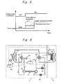
- Fig. 1 is a block diagram showing a refrigeration cycle apparatus according to a first embodiment of the present invention
- Fig. 2 is a time chart showing a control method of the refrigeration cycle apparatus of the embodiment.
- the refrigeration cycle apparatus shown in Fig. 1 includes a refrigerant circuit A into which a carbon dioxide refrigerant is charged as a refrigerant, and a fluid circuit B through which utilizing fluid flows.
- the refrigerant circuit A includes a compression mechanism 2 driven by an electric motor 1, a refrigerant flow path of a radiator 3 as a utilizing-side heat exchanger, an expansion mechanism 5 from which power is recovered by a power generator 4, an evaporator 6 as a heat source-side heat exchanger, and the like.
- the fluid circuit B includes a feed pump 7 as utilizing fluid transfer means, a fluid flow path of the radiator 3, a boiler 8, and the like.
- the refrigeration cycle apparatus of this embodiment includes an air blower 9 as heat source fluid transfer means for sending heat source fluid (e.g., outside air) to the evaporator 6, outside air temperature detection means 10 as heat source fluid temperature detection means for detecting the outside air temperature, water incoming temperature detection means 11 as utilizing fluid temperature detection means for detecting the temperature of utilizing fluid (e.g.
- heat source fluid e.g., outside air
- outside air temperature detection means 10 as heat source fluid temperature detection means for detecting the outside air temperature
- water incoming temperature detection means 11 as utilizing fluid temperature detection means for detecting the temperature of utilizing fluid
- starting pressure difference determination means 12 for determining whether a pressure difference at the time of starting operation of the compression mechanism 2 is small
- air blower revolution number operating means 13 as heat source fluid transfer amount operating means for calculating and operating the number of revolutions (revolution number, hereinafter) of the air blower 9 based on signals from the starting pressure difference determination means 12 and the like.
- the carbon dioxide refrigerant is compressed to a pressure exceeding a critical pressure by the compression mechanism 2.
- the compressed refrigerant is brought into a high temperature and high pressure state, and the refrigerant radiates heat to water flowing through the fluid flow path of the radiator 3 when the refrigerant flows through the refrigerant flow path of the radiator 3, and the refrigerant is cooled.
- the refrigerant is decompressed by the expansion mechanism 5 and is brought into a low temperature and low pressure liquid-gas two phase state.
- the pressure energy recovered by the expansion mechanism 5 at the time of expansion is transmitted to the power generator 4 and converted into electricity.
- the refrigerant decompressed by the expansion mechanism 5 is supplied to the evaporator 6.
- the refrigerant is heated by outside air sent by the air blower 9, and is brought into a liquid-gas two phase state or a gas state.
- the refrigerant which flows out from the evaporator 6 is sucked by the compression mechanism 2 again.
- utilizing fluid e.g., water
- the utilizing fluid is heated by a refrigerant flowing through the refrigerant flow path of the radiator 3, and becomes high temperature fluid (e.g., hot water).
- the high temperature fluid is stored in the boiler 8 from its top.
- the expansion mechanism 5 is of a scroll type, a refrigerant leaks from a gap generated between an orbiting scroll and a fixed scroll, the refrigerant can not be expanded sufficiently, and there is a high possibility that vibration or noise is generated, and that it takes time to start the refrigeration cycle apparatus.
- the starting pressure difference determination means 12 determines that a pressure difference at the time of starting operation becomes small, the air blower revolution number operating means 13 is appropriately controlled.
- the air blower 9 is started when a predetermined time (T) is elapsed after the compression mechanism 2 is started. After the predetermined time (T) is elapsed, the revolution number of the air blower 9 is brought into the target revolution number which is determined by operation frequency of the compression mechanism 2.
- T a predetermined time
- the revolution number of the air blower 9 is brought into the target revolution number which is determined by operation frequency of the compression mechanism 2.
- a detection value (outside air temperature Ta) from the outside air temperature detection means 10 is obtained (step 100).
- a detection value (water incoming temperature Tw) from the water incoming temperature detection means 11 is obtained (step 110).
- a predetermined outside air temperature (predetermined Ta) which is previously stored in a ROM or the like is compared with the outside air temperature obtained in step 100 (step 120), and/or a predetermined water incoming temperature (predetermined Tw) which is stored in the ROM or the like is compared with the water incoming temperature obtained in step 110 (step 120).
- the air blower 9 is started when the predetermined time (T) is elapsed after the compression mechanism 2 is started (step 130). In other cases, the air blower 9 is immediately started after the compression mechanism 2 is started in accordance with a normal starting method (step 140).
- a pressure (i.e., low pressure) in the evaporator 6 is reduced faster, and it is possible to generate a pressure difference upstream and downstream of the expansion mechanism 5 for a short time. Therefore, the operation of the expansion mechanism 5 does not become unstable, vibration and noise can be prevented, and the refrigeration cycle apparatus can swiftly be started.
- the starting pressure difference determination means 12 determines the pressure difference at the time of starting operation based on the outside air temperature or the water incoming temperature. Therefore, it is possible to inexpensively determine whether the pressure difference between upstream and downstream of the expansion mechanism 5 is small without using an expensive pressure sensor.
- the air blower 9 is stopped for the predetermined time (T) in the embodiment, the same effect can also be obtained even if the revolution number is lowered (reduced) to a value lower than the target revolution number for the predetermined time (T). Further, the predetermined time (T) may be varied in accordance with the outside air temperature or the water incoming temperature.
- the starting pressure difference determination means 12 determines whether the pressure difference upstream and downstream of the expansion mechanism 5 based on the outside air temperature or the water incoming temperature.
- the starting pressure difference determination means 12 may determine the same based on a detection value of pressure sensors provided upstream and downstream of the expansion mechanism 5, or a detection value of a temperature sensor which detects the temperature of the radiator 3 or the evaporator 6.
- the air blower 9 may always be stopped for the predetermined time (T) at the time of starting operation without depending on the determination of the starting pressure difference determination means 12.
- Fig. 4 is a block diagram showing a refrigeration cycle apparatus according to a second embodiment of the invention
- Fig. 5 is a time chart showing a control method of the refrigeration cycle apparatus of the embodiment.
- the air blower revolution number operating means 13 of the first embodiment is not provided. Instead, in the second embodiment, there is provided pump revolution number operating means 14 as the utilizing fluid transfer amount operating means which calculates and operates the revolution number of the feed pump 7 based on signals from the starting pressure difference determination means 12 and other elements.
- the pump revolution number operating means 14 is appropriately controlled.
- the feed pump 7 is started when the predetermined time (T) is elapsed after the compression mechanism 2 is started. After the predetermined time (T) is elapsed, the revolution number of the feed pump 7 is brought into a target revolution number determined by a water temperature (hot water outgoing temperature) at the outlet of the radiator 3.
- the pressure in the radiator 3 i.e. , high pressure
- the pressure difference can be generated upstream and downstream of the expansion mechanism 5 for a short time. Therefore, the operation of the expansion mechanism 5 does not become unstable, vibration and noise can be prevented, and the refrigeration cycle apparatus can swiftly be started.
- the feed pump 7 is stopped for the predetermined time (T) in this embodiment, the same effect can also be obtained even if the revolution number is lowered (reduced) to a value lower than the target revolution number for the predetermined time (T).
- the predetermined time (T) may be varied in accordance with the outside air temperature or the water incoming temperature.
- the starting pressure difference determination means 12 determines whether the pressure difference upstream and downstream of the expansion mechanism 5 is small based on the outside air temperature or the water incoming temperature. Alternatively, the starting pressure difference determination means 12 may determine the same based on a detection value of pressure sensors provided upstream and downstream of the expansion mechanism 5, or a detection value of a temperature sensor which detects the temperature of the radiator 3 or the evaporator 6. Alternatively, the feed pump 7 may always be stopped for the predetermined time (T) at the time of starting operation.
- the first and second embodiments have been explained while taking the case of the water heater, but the invention is not limited to the water heater, and the invention may be applied to an air conditioner.
- the pressure energy at the time of expansion by the expansion mechanism 5 is electrically recovered by the power generator 4 in the above explanation, the compression mechanism 2 and the expansion mechanism 5 may be connected to each other through one shaft, and the driving operation of the compression mechanism 2 may be assisted using the recovered energy.
- Fig. 6 is a block diagram showing a refrigeration cycle apparatus according to a third embodiment of the invention
- Fig. 7 is a time chart showing a control method of the refrigeration cycle apparatus of the embodiment.
- the refrigeration cycle apparatus shown in Fig. 6 has a refrigeration cycle.
- the refrigeration cycle includes a compression mechanism 22 driven by an electric motor 21, a first four-way valve 23 for switching between a cooling operation and a heating operation, a heat source-side heat exchanger 24, a second four-way valve 25, an expansion mechanism 27 which is connected to the compression mechanism 22 and the electric motor 21 through one shaft for recovering power, and a utilizing-side heat exchanger 28.
- R410A As a refrigerant, R410A is charged into the refrigeration cycle.
- the refrigeration cycle apparatus includes a bypass flow path 31 for bypassing the expansion mechanism 27, a bypass valve 32 for adjusting a flow rate of the refrigerant flowing into the expansion mechanism 27, and outside air temperature detection means 40 as heat source fluid temperature detection means for detecting the outside air temperature.
- the refrigeration cycle apparatus further includes a heat source-side air blower 29 as heat source fluid transfer means for sending heat source fluid (e.g., outside air) to the heat source-side heat exchanger 24, a utilizing-side air blower 30 as the utilizing fluid transfer means for sending utilizing fluid (e.g., air in a room) to the utilizing-side heat exchanger 28, indoor temperature detection means 41 as the utilizing fluid temperature detection means, starting pressure difference determination means 42 for determining whether a pressure difference when the refrigeration cycle apparatus is started is small, discharge temperature detection means 43 for detecting the temperature of a refrigerant discharged from the compression mechanism 22, and bypass valve opening operating means 44 for calculating and operating opening of the bypass valve 32 based on signals of the starting pressure difference determination means 42 and the discharge temperature detection means 43.
- heat source fluid e.g., outside air
- utilizing-side air blower 30 as the utilizing fluid transfer means for sending utilizing fluid (e.g., air in a room) to the utilizing-side heat exchanger 28
- indoor temperature detection means 41
- the refrigeration cycle apparatus includes an outdoor unit C and an indoor unit D.
- the outdoor unit C accommodates therein main constituent elements such as the compression mechanism 22, the first four-way valve 23, the heat source-side heat exchanger 24, the expansion mechanism 27, the heat source fluid temperature detection means 40 and the bypass valve opening operating means 44.
- the indoor unit D accommodates the utilizing-side heat exchanger 28, the utilizing-side air blower 30 and the utilizing fluid temperature detection means 41.
- a refrigerant compressed by the compression mechanism 22 is brought into high temperature and high pressure state, and flows into the heat source-side heat exchanger 24 through the first four-way valve 23 which is switched in the direction of the solid line in the drawing.
- the heat source-side heat exchanger 24 functions as a radiator, and the refrigerant is cooled by a heat source fluid (e.g., outside air) sent by the heat source-side air blower 29.
- a heat source fluid e.g., outside air
- the refrigerant flows through the second four-way valve 25 which is switched in the direction of the solid line in the drawing and then, the refrigerant is decompressed to an intermediate pressure by a pre-decompressor 26 such that the density of the refrigerant becomes appropriate density, and the refrigerant flows into the expansion mechanism 27. Then, the refrigerant is decompressed by the expansion mechanism 27, and is brought into a low temperature and low pressure liquid-gas two phase state. The pressure energy when the power is recovered by the expansion mechanism 27 at the time of expansion assists the operation of the compression mechanism 22 through the connected shaft.
- the refrigerant decompressed by the expansion mechanism 27 is supplied to the utilizing-side heat exchanger 28.
- the utilizing-side heat exchanger 28 functions as an evaporator.
- the refrigerant is heated by a utilizing fluid (e. g. , air in a room) sent by the utilizing-side air blower 30, and is brought into a liquid-gas two phase state or a gas state.
- the refrigerant which flows out from the utilizing-side heat exchanger 28 is sucked by the compression mechanism 22 again.
- the refrigeration cycle apparatus of the embodiment can cool a room in which an indoor unit C is disposed.
- the refrigerant compressed by the compression mechanism 22 is brought into a high temperature and high pressure state, and flows into the utilizing-side heat exchanger 28 through the first four-way valve 23 which is switched in the direction of the broken line in the drawing.
- the utilizing-side heat exchanger 28 functions as a radiator, and the refrigerant is cooled by a utilizing fluid (e.g., air in a room) sent by the utilizing-side air blower 30.
- a utilizing fluid e.g., air in a room
- the refrigerant flows through the second four-way valve 25 which is switched in the direction of the broken line in the drawing and then, the refrigerant is decompressed to an intermediate pressure by a pre-decompressor 26 such that the density of the refrigerant becomes appropriate density, and the refrigerant flows into the expansion mechanism 27. Then, the refrigerant is decompressed by the expansion mechanism 27, and is brought into a low temperature and low pressure liquid-gas two phase state. The pressure energy when the power is recovered by the expansion mechanism 27 at the time of expansion assists the operation of the compression mechanism 22 through the connected shaft.
- the refrigerant decompressed by the expansion mechanism 27 is supplied to the heat source-side heat exchanger 24.
- the heat source-side heat exchanger 24 functions as an evaporator, the refrigerant is heated by a heat source fluid (e.g., outside air) sent by the heat source-side air blower 29, and the refrigerant is brought into a liquid-gas two phase state or a gas state.
- the refrigerant which flows out from the heat source-side heat exchanger 24 is again sucked by the compression mechanism 22.
- the refrigeration cycle apparatus of the embodiment can heat the room where the indoor unit C is disposed.
- the bypass valve opening operating means 44 is appropriately controlled when the starting pressure difference determination means 42 determines that a pressure difference at the time of starting operation becomes small.
- the refrigeration cycle apparatus is started while reducing an opening of the bypass valve 32 as compared with an opening of the bypass valve 32 at the time of normal operation for the predetermined time (T) after the compression mechanism 22 is started, and the opening of the bypass valve 32 is set to the target opening after the predetermined time (T) is elapsed.
- the pressure difference can be generated upstream and downstream of the expansion mechanism 27 for a short time. Therefore, the operation of the expansion mechanism 27 does not become unstable, vibration and noise can be prevented, and the refrigeration cycle apparatus can swiftly be started.
- a detection value (outside air temperature Ta1) from the outside air temperature detection means 40 is obtained (step 200).
- a detection value (indoor temperature Ta2) from the indoor temperature detection means 41 is obtained (step210).
- it is determined whether the operation mode is a cooling operation mode (step 220). If the operation mode is a cooling operation mode, the procedure is proceeded to step 230, and if the operation mode is a heating operation mode, the procedure is proceeded to step 240.
- a predetermined outside air temperature (predetermined Ta1) which is previously stored in a ROM or the like and the outside air temperature obtained in step 200 are compared with each other (step 230), and/or the indoor temperature (predetermined Ta2) which is previously stored in the ROM or the like and the indoor temperature obtained in step 210 are compared with each other (step 230).
- predetermined Ta1 which is previously stored in a ROM or the like and the outside air temperature obtained in step 200
- the indoor temperature predetermined Ta2 which is previously stored in the ROM or the like and the indoor temperature obtained in step 210 are compared with each other (step 230).
- the predetermined outside air temperature (predetermined Ta1) and the outside air temperature obtained in step 200 are compared with each other (step 240), and/or the predetermined indoor temperature (predetermined Ta2) and the indoor temperature obtained in step 210 are compared with each other (step 240), and when the outside air temperature is higher than the predetermined outside air temperature, and/or when the indoor temperature is lower than the predetermined indoor temperature, the procedure is proceeded to step 250. In other cases, the procedure is proceeded to step 260.
- the opening of the bypass valve 32 is corrected to a smaller value than the opening set by control at the time of normal operation (target opening suitable for the discharge temperature Td in the case of this embodiment for example) for the predetermined time (T) after the compression mechanism 22 is started (step 250). In other cases, the opening of the bypass valve 32 is set to the target opening set by control at the time of normal operation, and the target opening is not corrected (step 260).
- the control method of the refrigeration cycle apparatus of the embodiment when the indoor temperature at the time of the cooling operation or the outside air temperature at the time of heating operation is high, or when the outside air temperature at the time of cooling operation or the indoor temperature at the time of heating operation is low, a pressure difference can be generated upstream and downstream of the expansion mechanism 27 for a short time. Therefore, the operation of the expansion mechanism 27 does not become unstable, vibration and noise can be prevented, and the refrigeration cycle apparatus can swiftly be started.
- the starting pressure difference determination means 42 determines the pressure difference at the time of starting operation based on the outside air temperature or the indoor temperature. Therefore, it is possible to inexpensively determine whether the pressure difference between upstream and downstream of the expansion mechanism 5 is small without using an expensive pressure sensor.
- a correction value for correcting the target opening of the bypass valve 32 or the predetermined time (T) may be varied in accordance with the outside air temperature or the indoor temperature.
- the starting pressure difference determination means 42 determines whether the pressure difference at the time of starting operation is small based on the outside air temperature or the indoor temperature.
- the starting pressure difference determination means 42 may determinate based on other detection values such as detection values of pressure sensors provided upstream and downstream of the expansion mechanism 27 or a detection value of a temperature sensor which detects the temperature of the heat source-side heat exchanger 24 or the utilizing-side heat exchanger 28.
- the opening of the bypass valve 32 may always be reduced for the predetermined time (T) without depending on the determination of the starting pressure difference determination means 42.
- Fig. 9 is a block diagram showing a refrigeration cycle apparatus according to a fourth embodiment of the invention
- Fig. 10 is a time chart showing a control method of the refrigeration cycle apparatus of the embodiment.
- the refrigeration cycle of the embodiment includes the compression mechanism 22, the first four-way valve 23, the heat source-side heat exchanger 24, the second four-way valve 25, the pre-decompressor 26 which previously decompresses a refrigerant which flows into the expansion mechanism 27, the expansion mechanism 27 and the utilizing-side heat exchanger 28.
- bypass valve opening operating means 44 of the third embodiment is not provided. Instead, there is provided pre-decompressor opening operating means 45 which calculates and operates the opening of the pre-decompressor 26 based on signals from the starting pressure difference determination means 42 and the discharge temperature detection means 43.
- the pre-decompressor opening operating means 45 is appropriately controlled when the starting pressure difference determination means 42 determines that a pressure difference at the time of starting operation becomes small.
- the opening of the pre-decompressor 26 is reduced to a value smaller than the opening at the time of normal operation for the predetermined time (T), and after the predetermined time (T) is elapsed, the opening of the pre-decompressor 26 is set to the target opening.
- a correction value for correcting the target opening of the bypass valve 32 or the predetermined time (T) may be varied in accordance with the outside air temperature or the indoor temperature.
- the starting pressure difference determination means 42 determines whether the pressure difference at the time of starting operation is small based on the outside air temperature or the indoor temperature.
- the starting pressure difference determination means 42 may determinate based on other detection values such as detection values of pressure sensors provided upstream and downstream of the expansion mechanism 27 or a detection value of a temperature sensor which detects the temperature of the heat source-side heat exchanger 24 or the utilizing-side heat exchanger 28.
- the opening of the pre-decompressor 26 may always be reduced at the time of starting operation for the predetermined time (T).
- the present invention should not be limited to the air conditioner, and the invention may be applied to a water heater.
- the pressure energy at the time of expansion by the expansion mechanism 27 is utilized for assisting the operation of the compression mechanism 22 through the connected shaft, the pressure energy may be electrically recovered using a power generator.
- the control method of the refrigeration cycle apparatus and the refrigeration cycle apparatus using the control method can enhance the starting performance in a boiler, an air conditioner, a vehicular air conditioner having the expansion mechanism.
Landscapes
- Engineering & Computer Science (AREA)
- Physics & Mathematics (AREA)
- Mechanical Engineering (AREA)
- Thermal Sciences (AREA)
- General Engineering & Computer Science (AREA)
- Air Conditioning Control Device (AREA)
- Air-Conditioning For Vehicles (AREA)
- Devices That Are Associated With Refrigeration Equipment (AREA)
- Compression-Type Refrigeration Machines With Reversible Cycles (AREA)
Priority Applications (1)
| Application Number | Priority Date | Filing Date | Title |
|---|---|---|---|
| EP06023836A EP1775529B1 (fr) | 2004-11-04 | 2005-10-27 | Méthode de contrôle d'un cycle frigorifique et cycle frigorifique employant la dite méthode |
Applications Claiming Priority (1)
| Application Number | Priority Date | Filing Date | Title |
|---|---|---|---|
| JP2004320225A JP2006132818A (ja) | 2004-11-04 | 2004-11-04 | 冷凍サイクル装置の制御方法およびそれを用いた冷凍サイクル装置 |
Related Child Applications (1)
| Application Number | Title | Priority Date | Filing Date |
|---|---|---|---|
| EP06023836A Division EP1775529B1 (fr) | 2004-11-04 | 2005-10-27 | Méthode de contrôle d'un cycle frigorifique et cycle frigorifique employant la dite méthode |
Publications (3)
| Publication Number | Publication Date |
|---|---|
| EP1655558A1 true EP1655558A1 (fr) | 2006-05-10 |
| EP1655558A8 EP1655558A8 (fr) | 2007-02-21 |
| EP1655558B1 EP1655558B1 (fr) | 2007-08-01 |
Family
ID=35355108
Family Applications (2)
| Application Number | Title | Priority Date | Filing Date |
|---|---|---|---|
| EP06023836A Expired - Fee Related EP1775529B1 (fr) | 2004-11-04 | 2005-10-27 | Méthode de contrôle d'un cycle frigorifique et cycle frigorifique employant la dite méthode |
| EP05023541A Expired - Fee Related EP1655558B1 (fr) | 2004-11-04 | 2005-10-27 | Méthode de contrôle d'un cycle frigorifique et cycle frigorifique employant la dite méthode |
Family Applications Before (1)
| Application Number | Title | Priority Date | Filing Date |
|---|---|---|---|
| EP06023836A Expired - Fee Related EP1775529B1 (fr) | 2004-11-04 | 2005-10-27 | Méthode de contrôle d'un cycle frigorifique et cycle frigorifique employant la dite méthode |
Country Status (5)
| Country | Link |
|---|---|
| US (2) | US7765816B2 (fr) |
| EP (2) | EP1775529B1 (fr) |
| JP (1) | JP2006132818A (fr) |
| CN (2) | CN100335851C (fr) |
| DE (2) | DE602005001830T2 (fr) |
Cited By (3)
| Publication number | Priority date | Publication date | Assignee | Title |
|---|---|---|---|---|
| EP2009370A1 (fr) * | 2007-06-27 | 2008-12-31 | Sanden Corporation | Chauffe-eau |
| WO2010072766A3 (fr) * | 2008-12-23 | 2011-03-24 | Reinhard Liehs | Dispositif pour la production de courant électrique |
| EP2927614A4 (fr) * | 2012-11-29 | 2016-08-17 | Mitsubishi Electric Corp | Dispositif de climatisation |
Families Citing this family (51)
| Publication number | Priority date | Publication date | Assignee | Title |
|---|---|---|---|---|
| US8672732B2 (en) | 2006-01-19 | 2014-03-18 | Schneider Electric It Corporation | Cooling system and method |
| US8091375B2 (en) * | 2006-05-10 | 2012-01-10 | Trane International Inc. | Humidity control for air conditioning system |
| US8322155B2 (en) | 2006-08-15 | 2012-12-04 | American Power Conversion Corporation | Method and apparatus for cooling |
| US8327656B2 (en) | 2006-08-15 | 2012-12-11 | American Power Conversion Corporation | Method and apparatus for cooling |
| US9568206B2 (en) | 2006-08-15 | 2017-02-14 | Schneider Electric It Corporation | Method and apparatus for cooling |
| JP4179365B2 (ja) * | 2006-08-31 | 2008-11-12 | ダイキン工業株式会社 | 空気調和装置 |
| US7681404B2 (en) | 2006-12-18 | 2010-03-23 | American Power Conversion Corporation | Modular ice storage for uninterruptible chilled water |
| US8425287B2 (en) | 2007-01-23 | 2013-04-23 | Schneider Electric It Corporation | In-row air containment and cooling system and method |
| JP5103952B2 (ja) * | 2007-03-08 | 2012-12-19 | ダイキン工業株式会社 | 冷凍装置 |
| JP4225357B2 (ja) * | 2007-04-13 | 2009-02-18 | ダイキン工業株式会社 | 冷媒充填装置、冷凍装置及び冷媒充填方法 |
| JP5559040B2 (ja) | 2007-05-15 | 2014-07-23 | シュナイダー エレクトリック アイティー コーポレーション | 設備の電力及び冷却を管理するための方法及びシステム |
| US20110023533A1 (en) * | 2008-05-22 | 2011-02-03 | Mitsubishi Electric Corporation | Refrigerating cycle device |
| JP4929519B2 (ja) * | 2009-02-19 | 2012-05-09 | ダイキン工業株式会社 | チリング式冷凍システム |
| US8219362B2 (en) | 2009-05-08 | 2012-07-10 | American Power Conversion Corporation | System and method for arranging equipment in a data center |
| US8397088B1 (en) | 2009-07-21 | 2013-03-12 | The Research Foundation Of State University Of New York | Apparatus and method for efficient estimation of the energy dissipation of processor based systems |
| EP2476973B9 (fr) | 2009-10-07 | 2019-02-13 | Mitsubishi Electric Corporation | Dispositif à cycle de réfrigération |
| US8972217B2 (en) | 2010-06-08 | 2015-03-03 | Schneider Electric It Corporation | System and method for predicting temperature values in a data center |
| US8509959B2 (en) | 2010-08-12 | 2013-08-13 | Schneider Electric It Corporation | System and method for predicting transient cooling performance for a data center |
| US8996180B2 (en) | 2010-09-17 | 2015-03-31 | Schneider Electric It Corporation | System and method for predicting perforated tile airflow in a data center |
| WO2012081052A1 (fr) * | 2010-12-15 | 2012-06-21 | 三菱電機株式会社 | Système combiné de climatisation et de distribution d'eau chaude |
| US8688413B2 (en) | 2010-12-30 | 2014-04-01 | Christopher M. Healey | System and method for sequential placement of cooling resources within data center layouts |
| US9223905B2 (en) | 2011-03-25 | 2015-12-29 | Schneider Electric It Corporation | Systems and methods for predicting fluid dynamics in a data center |
| US8725307B2 (en) | 2011-06-28 | 2014-05-13 | Schneider Electric It Corporation | System and method for measurement aided prediction of temperature and airflow values in a data center |
| AU2011384046A1 (en) | 2011-12-22 | 2014-07-17 | Schneider Electric It Corporation | Analysis of effect of transient events on temperature in a data center |
| EP2796025A4 (fr) | 2011-12-22 | 2016-06-29 | Schneider Electric It Corp | Système et procédé de prédiction de valeurs de température dans un système électronique |
| CN102620468B (zh) * | 2012-04-13 | 2013-04-24 | 太原理工大学 | 太阳能喷射与变速压缩复合制冷装置 |
| CN102635972B (zh) * | 2012-04-13 | 2013-04-17 | 太原理工大学 | 蓄冷式太阳能喷射与压缩耦合制冷装置 |
| JP5841921B2 (ja) * | 2012-09-06 | 2016-01-13 | ヤンマー株式会社 | エンジン駆動ヒートポンプチラー |
| WO2014136447A1 (fr) * | 2013-03-06 | 2014-09-12 | パナソニック株式会社 | Dispositif de climatisation de véhicule |
| EP3150935B1 (fr) * | 2014-05-30 | 2019-03-06 | Mitsubishi Electric Corporation | Climatiseur |
| JP6248878B2 (ja) * | 2014-09-18 | 2017-12-20 | 株式会社富士通ゼネラル | 空気調和装置 |
| CN108072201B (zh) | 2016-11-11 | 2022-02-01 | 开利公司 | 热泵系统及其启动控制方法 |
| IT201700088696A1 (it) * | 2017-08-01 | 2019-02-01 | De Longhi Appliances Srl | Metodo di regolazione di un apparato di condizionamento |
| US11154004B2 (en) | 2019-04-26 | 2021-10-26 | Deere & Company | Agricultural seed sensing and control system |
| CN110145895B (zh) * | 2019-06-17 | 2024-08-02 | 李国庆 | 一种涡旋制冷动力机 |
| CN110849014A (zh) * | 2019-10-17 | 2020-02-28 | 安徽正刚新能源科技有限公司 | Mw级跨临界二氧化碳冷热联供装置能源回收系统 |
| CN110986224B (zh) * | 2019-11-07 | 2021-05-14 | 珠海格力电器股份有限公司 | 一种空调器及其控制方法、存储介质 |
| US11097512B1 (en) | 2020-01-31 | 2021-08-24 | Champion Link Intern Aiton Al Corporation | Floor panel and method of manufacturing a floor panel |
| US11718565B2 (en) | 2020-01-31 | 2023-08-08 | Champion Link International Corporation | Panel for forming a floor covering and such floor covering |
| US11927020B2 (en) | 2020-01-31 | 2024-03-12 | Champion Link International Corporation | Floor panel and method of manufacturing a floor panel |
| US11391049B2 (en) * | 2020-01-31 | 2022-07-19 | Champion Link International Corporation | Panel and method of producing such a panel |
| US11053696B1 (en) * | 2020-01-31 | 2021-07-06 | Champion Link International Corporation | Panel for forming a floor covering and such floor covering |
| US11542712B2 (en) | 2020-03-13 | 2023-01-03 | Champion Link International Corporation | Panel and method of producing a panel |
| US11149441B2 (en) | 2020-03-13 | 2021-10-19 | Champion Link International Corporation | Panel and method of producing a panel |
| US11724537B2 (en) | 2020-05-26 | 2023-08-15 | Champion Link International Corporation | Panel and method for producing a panel |
| NL2025684B1 (en) | 2020-05-26 | 2021-12-14 | Champion Link Int Corp | Panel and method for producing a panel |
| US11530536B2 (en) | 2020-07-15 | 2022-12-20 | Champion Link International Corporation | Panel |
| US11326356B2 (en) | 2020-07-15 | 2022-05-10 | Champion Link International Corporation | Floor or wall panel |
| TWI771882B (zh) | 2021-01-27 | 2022-07-21 | 群光電能科技股份有限公司 | 電源供應器及驅動方法 |
| TWI746387B (zh) | 2021-03-08 | 2021-11-11 | 群光電能科技股份有限公司 | 電源供應器及其操作方法 |
| CN114893921B (zh) * | 2022-05-24 | 2023-08-08 | 青岛海信日立空调系统有限公司 | 一种磁悬浮冷水机组 |
Citations (14)
| Publication number | Priority date | Publication date | Assignee | Title |
|---|---|---|---|---|
| JPS5765533A (en) * | 1980-10-06 | 1982-04-21 | Mitsubishi Electric Corp | Air conditioner |
| JPH03164662A (ja) * | 1989-11-21 | 1991-07-16 | Mitsubishi Electric Corp | 冷蔵庫 |
| JPH06193978A (ja) * | 1992-12-24 | 1994-07-15 | Nippondenso Co Ltd | 車両用空気調和装置 |
| JPH07305904A (ja) * | 1994-05-11 | 1995-11-21 | Matsushita Refrig Co Ltd | 冷蔵庫 |
| JPH08303921A (ja) * | 1995-04-28 | 1996-11-22 | Matsushita Refrig Co Ltd | 冷蔵庫 |
| JP2000028184A (ja) * | 1998-07-13 | 2000-01-25 | Fujitsu General Ltd | 空気調和機の制御方法 |
| JP2001165513A (ja) * | 1999-12-03 | 2001-06-22 | Aisin Seiki Co Ltd | 冷凍空調機 |
| JP2003042574A (ja) * | 2001-08-01 | 2003-02-13 | Denso Corp | 蒸気圧縮式冷凍機 |
| JP2003182349A (ja) * | 2001-12-14 | 2003-07-03 | Denso Corp | 冷凍サイクル装置 |
| US6591618B1 (en) * | 2002-08-12 | 2003-07-15 | Praxair Technology, Inc. | Supercritical refrigeration system |
| US20030209032A1 (en) * | 2002-05-13 | 2003-11-13 | Hiromi Ohta | Vapor compression refrigerant cycle |
| DE10220870A1 (de) * | 2002-05-11 | 2003-11-20 | Juergen Uehlin | Autonome Wärmepumpe |
| EP1416232A1 (fr) * | 2002-10-31 | 2004-05-06 | Matsushita Electric Industrial Co., Ltd. | Méthode pour déterminer la haute pression dans un système frigorifique |
| US6739141B1 (en) * | 2003-02-12 | 2004-05-25 | Carrier Corporation | Supercritical pressure regulation of vapor compression system by use of gas cooler fluid pumping device |
Family Cites Families (34)
| Publication number | Priority date | Publication date | Assignee | Title |
|---|---|---|---|---|
| JPS5165456A (ja) * | 1974-12-04 | 1976-06-07 | Hitachi Ltd | Reitosochi |
| JPS56112896A (en) | 1980-02-12 | 1981-09-05 | Toshiba Corp | Freezing device |
| US4366425A (en) * | 1981-04-21 | 1982-12-28 | Shen Chou Ming | Timer-controlled speed changing device for electric fans |
| US4860552A (en) * | 1988-12-23 | 1989-08-29 | Honeywell, Inc. | Heat pump fan control |
| JPH0277546A (ja) * | 1989-06-21 | 1990-03-16 | Ndc Co Ltd | Al―Sn―Pb系軸受合金 |
| JPH0331643A (ja) * | 1989-06-29 | 1991-02-12 | Mitsubishi Electric Corp | 空気調和装置 |
| JPH0359350A (ja) * | 1989-07-28 | 1991-03-14 | Toshiba Corp | 空気調和機 |
| US4941325A (en) * | 1989-09-06 | 1990-07-17 | Nuding Douglas J | Energy efficient electronic control system for air-conditioning and heat pump systems |
| US5095714A (en) * | 1989-12-25 | 1992-03-17 | Daikin Industries, Ltd. | Surging prediction device for a centrifugal compressor |
| EP0449641B1 (fr) * | 1990-03-30 | 1995-05-10 | Mitsubishi Denki Kabushiki Kaisha | Système de conditionnement d'air |
| JPH043844A (ja) * | 1990-04-20 | 1992-01-08 | Hitachi Ltd | 空気調和機の制御方法 |
| JP2500519B2 (ja) * | 1990-12-25 | 1996-05-29 | ダイキン工業株式会社 | 空気調和装置の運転制御装置 |
| JP2630128B2 (ja) * | 1991-09-11 | 1997-07-16 | ダイキン工業株式会社 | 冷凍装置の容量制御装置 |
| JPH05196309A (ja) | 1992-01-22 | 1993-08-06 | Daikin Ind Ltd | 空調機の運転制御方法 |
| JP3209801B2 (ja) * | 1992-08-31 | 2001-09-17 | 東芝キヤリア株式会社 | 空気調和機 |
| US5303562A (en) * | 1993-01-25 | 1994-04-19 | Copeland Corporation | Control system for heat pump/air-conditioning system for improved cyclic performance |
| DE69533120D1 (de) * | 1994-05-30 | 2004-07-15 | Mitsubishi Electric Corp | Kühlmittelumlaufsystem |
| JPH0828969A (ja) * | 1994-07-15 | 1996-02-02 | Sanyo Electric Co Ltd | 冷却装置 |
| JP3546544B2 (ja) | 1995-07-06 | 2004-07-28 | ダイキン工業株式会社 | 空気調和機の起動運転制御装置 |
| US5771700A (en) * | 1995-11-06 | 1998-06-30 | Ecr Technologies, Inc. | Heat pump apparatus and related methods providing enhanced refrigerant flow control |
| JPH09158851A (ja) * | 1995-12-12 | 1997-06-17 | Mitsubishi Heavy Ind Ltd | スクロール型流体機械 |
| US5918474A (en) * | 1996-07-30 | 1999-07-06 | Whirlpool Corporation | Fan motor on/off control system for a refrigeration appliance |
| JPH10197083A (ja) * | 1997-01-10 | 1998-07-31 | Calsonic Corp | 自動車用気体圧縮式冷房装置 |
| CN2365605Y (zh) * | 1998-01-07 | 2000-02-23 | 周劲松 | 制冷机节能器 |
| US6321564B1 (en) * | 1999-03-15 | 2001-11-27 | Denso Corporation | Refrigerant cycle system with expansion energy recovery |
| JP3995915B2 (ja) * | 2000-10-12 | 2007-10-24 | 株式会社マック | 流体温度の制御方法及びその装置 |
| US6883339B2 (en) * | 2001-04-04 | 2005-04-26 | Lg Electronics Inc. | Method for controlling power saving operation of refrigerator with two evaporator |
| JP4251785B2 (ja) * | 2001-04-18 | 2009-04-08 | 株式会社デンソー | ヒートポンプ式温水器 |
| JP4031223B2 (ja) * | 2001-09-27 | 2008-01-09 | アネスト岩田株式会社 | スクロール式流体機械 |
| JP3915538B2 (ja) * | 2002-02-20 | 2007-05-16 | ダイキン工業株式会社 | 給湯機 |
| JP3953871B2 (ja) * | 2002-04-15 | 2007-08-08 | サンデン株式会社 | 冷凍空調装置 |
| US6595024B1 (en) * | 2002-06-25 | 2003-07-22 | Carrier Corporation | Expressor capacity control |
| JP4233843B2 (ja) * | 2002-10-31 | 2009-03-04 | パナソニック株式会社 | 冷凍サイクル装置 |
| JP2004183982A (ja) * | 2002-12-03 | 2004-07-02 | Fujitsu General Ltd | 空気調和機の制御装置 |
-
2004
- 2004-11-04 JP JP2004320225A patent/JP2006132818A/ja active Pending
-
2005
- 2005-10-27 EP EP06023836A patent/EP1775529B1/fr not_active Expired - Fee Related
- 2005-10-27 DE DE602005001830T patent/DE602005001830T2/de not_active Expired - Lifetime
- 2005-10-27 EP EP05023541A patent/EP1655558B1/fr not_active Expired - Fee Related
- 2005-10-27 DE DE602005009544T patent/DE602005009544D1/de not_active Expired - Lifetime
- 2005-11-04 US US11/266,494 patent/US7765816B2/en not_active Expired - Fee Related
- 2005-11-04 CN CNB200510118687XA patent/CN100335851C/zh not_active Expired - Fee Related
- 2005-11-04 CN CNB2007100884248A patent/CN100516712C/zh not_active Expired - Fee Related
-
2010
- 2010-01-13 US US12/656,007 patent/US20100115974A1/en not_active Abandoned
Patent Citations (14)
| Publication number | Priority date | Publication date | Assignee | Title |
|---|---|---|---|---|
| JPS5765533A (en) * | 1980-10-06 | 1982-04-21 | Mitsubishi Electric Corp | Air conditioner |
| JPH03164662A (ja) * | 1989-11-21 | 1991-07-16 | Mitsubishi Electric Corp | 冷蔵庫 |
| JPH06193978A (ja) * | 1992-12-24 | 1994-07-15 | Nippondenso Co Ltd | 車両用空気調和装置 |
| JPH07305904A (ja) * | 1994-05-11 | 1995-11-21 | Matsushita Refrig Co Ltd | 冷蔵庫 |
| JPH08303921A (ja) * | 1995-04-28 | 1996-11-22 | Matsushita Refrig Co Ltd | 冷蔵庫 |
| JP2000028184A (ja) * | 1998-07-13 | 2000-01-25 | Fujitsu General Ltd | 空気調和機の制御方法 |
| JP2001165513A (ja) * | 1999-12-03 | 2001-06-22 | Aisin Seiki Co Ltd | 冷凍空調機 |
| JP2003042574A (ja) * | 2001-08-01 | 2003-02-13 | Denso Corp | 蒸気圧縮式冷凍機 |
| JP2003182349A (ja) * | 2001-12-14 | 2003-07-03 | Denso Corp | 冷凍サイクル装置 |
| DE10220870A1 (de) * | 2002-05-11 | 2003-11-20 | Juergen Uehlin | Autonome Wärmepumpe |
| US20030209032A1 (en) * | 2002-05-13 | 2003-11-13 | Hiromi Ohta | Vapor compression refrigerant cycle |
| US6591618B1 (en) * | 2002-08-12 | 2003-07-15 | Praxair Technology, Inc. | Supercritical refrigeration system |
| EP1416232A1 (fr) * | 2002-10-31 | 2004-05-06 | Matsushita Electric Industrial Co., Ltd. | Méthode pour déterminer la haute pression dans un système frigorifique |
| US6739141B1 (en) * | 2003-02-12 | 2004-05-25 | Carrier Corporation | Supercritical pressure regulation of vapor compression system by use of gas cooler fluid pumping device |
Non-Patent Citations (9)
| Title |
|---|
| PATENT ABSTRACTS OF JAPAN vol. 006, no. 146 (M - 147) 5 August 1982 (1982-08-05) * |
| PATENT ABSTRACTS OF JAPAN vol. 015, no. 400 (M - 1167) 11 October 1991 (1991-10-11) * |
| PATENT ABSTRACTS OF JAPAN vol. 018, no. 550 (M - 1690) 20 October 1994 (1994-10-20) * |
| PATENT ABSTRACTS OF JAPAN vol. 1996, no. 03 29 March 1996 (1996-03-29) * |
| PATENT ABSTRACTS OF JAPAN vol. 1997, no. 03 31 March 1997 (1997-03-31) * |
| PATENT ABSTRACTS OF JAPAN vol. 2000, no. 04 31 August 2000 (2000-08-31) * |
| PATENT ABSTRACTS OF JAPAN vol. 2000, no. 23 10 February 2001 (2001-02-10) * |
| PATENT ABSTRACTS OF JAPAN vol. 2003, no. 06 3 June 2003 (2003-06-03) * |
| PATENT ABSTRACTS OF JAPAN vol. 2003, no. 11 5 November 2003 (2003-11-05) * |
Cited By (3)
| Publication number | Priority date | Publication date | Assignee | Title |
|---|---|---|---|---|
| EP2009370A1 (fr) * | 2007-06-27 | 2008-12-31 | Sanden Corporation | Chauffe-eau |
| WO2010072766A3 (fr) * | 2008-12-23 | 2011-03-24 | Reinhard Liehs | Dispositif pour la production de courant électrique |
| EP2927614A4 (fr) * | 2012-11-29 | 2016-08-17 | Mitsubishi Electric Corp | Dispositif de climatisation |
Also Published As
| Publication number | Publication date |
|---|---|
| JP2006132818A (ja) | 2006-05-25 |
| EP1655558B1 (fr) | 2007-08-01 |
| CN101033895A (zh) | 2007-09-12 |
| DE602005009544D1 (de) | 2008-10-16 |
| CN100335851C (zh) | 2007-09-05 |
| EP1775529A1 (fr) | 2007-04-18 |
| DE602005001830T2 (de) | 2008-04-17 |
| EP1655558A8 (fr) | 2007-02-21 |
| DE602005001830D1 (de) | 2007-09-13 |
| US7765816B2 (en) | 2010-08-03 |
| EP1775529B1 (fr) | 2008-09-03 |
| US20060096306A1 (en) | 2006-05-11 |
| CN1769815A (zh) | 2006-05-10 |
| US20100115974A1 (en) | 2010-05-13 |
| CN100516712C (zh) | 2009-07-22 |
Similar Documents
| Publication | Publication Date | Title |
|---|---|---|
| EP1775529B1 (fr) | Méthode de contrôle d'un cycle frigorifique et cycle frigorifique employant la dite méthode | |
| US6505476B1 (en) | Refrigerant cycle system with super-critical refrigerant pressure | |
| US8590326B2 (en) | Refrigeration cycle apparatus | |
| EP1416231B1 (fr) | Appareil frigorifique | |
| JP5776314B2 (ja) | ヒートポンプ給湯機 | |
| JPH071954A (ja) | 電気自動車用空気調和装置 | |
| JP6749471B2 (ja) | 空気調和装置 | |
| EP2096377B1 (fr) | Appareil de refrigeration | |
| JP4258944B2 (ja) | 超臨界蒸気圧縮機式冷凍サイクル | |
| JP2005048973A (ja) | 空気調和機及び空気調和機の制御方法 | |
| EP1830143A2 (fr) | Circuit de réfrigération | |
| JP2010038463A (ja) | 冷凍サイクル装置 | |
| JPH0571822A (ja) | 空気調和機 | |
| JP5516332B2 (ja) | ヒートポンプ式温水暖房機 | |
| JP4430406B2 (ja) | 冷凍サイクル装置 | |
| JP2008014602A (ja) | 冷凍サイクル装置 | |
| JP2007212024A (ja) | 冷凍サイクル装置および冷凍サイクル装置の制御方法 | |
| JP2008039237A (ja) | 冷凍サイクル装置 | |
| JP4665736B2 (ja) | 冷凍サイクル装置の制御方法およびそれを用いた冷凍サイクル装置 | |
| JP2007170765A (ja) | 冷凍サイクル装置の運転方法 | |
| JP4052020B2 (ja) | ヒートポンプシステム | |
| JP4575844B2 (ja) | 回転機械 | |
| JP2009115385A (ja) | 冷凍装置 | |
| JP3932921B2 (ja) | エンジン駆動式冷凍サイクル装置及び空調装置 | |
| JP2004205163A (ja) | 冷凍装置 |
Legal Events
| Date | Code | Title | Description |
|---|---|---|---|
| PUAI | Public reference made under article 153(3) epc to a published international application that has entered the european phase |
Free format text: ORIGINAL CODE: 0009012 |
|
| AK | Designated contracting states |
Kind code of ref document: A1 Designated state(s): AT BE BG CH CY CZ DE DK EE ES FI FR GB GR HU IE IS IT LI LT LU LV MC NL PL PT RO SE SI SK TR |
|
| AX | Request for extension of the european patent |
Extension state: AL BA HR MK YU |
|
| 17P | Request for examination filed |
Effective date: 20060530 |
|
| 17Q | First examination report despatched |
Effective date: 20060703 |
|
| AKX | Designation fees paid |
Designated state(s): DE |
|
| RAP1 | Party data changed (applicant data changed or rights of an application transferred) |
Owner name: MATSUSHITA ELECTRIC INDUSTRIAL CO., LTD. |
|
| GRAP | Despatch of communication of intention to grant a patent |
Free format text: ORIGINAL CODE: EPIDOSNIGR1 |
|
| GRAS | Grant fee paid |
Free format text: ORIGINAL CODE: EPIDOSNIGR3 |
|
| GRAA | (expected) grant |
Free format text: ORIGINAL CODE: 0009210 |
|
| AK | Designated contracting states |
Kind code of ref document: B1 Designated state(s): DE |
|
| REF | Corresponds to: |
Ref document number: 602005001830 Country of ref document: DE Date of ref document: 20070913 Kind code of ref document: P |
|
| PLBE | No opposition filed within time limit |
Free format text: ORIGINAL CODE: 0009261 |
|
| STAA | Information on the status of an ep patent application or granted ep patent |
Free format text: STATUS: NO OPPOSITION FILED WITHIN TIME LIMIT |
|
| 26N | No opposition filed |
Effective date: 20080506 |
|
| PGFP | Annual fee paid to national office [announced via postgrant information from national office to epo] |
Ref country code: DE Payment date: 20121024 Year of fee payment: 8 |
|
| REG | Reference to a national code |
Ref country code: DE Ref legal event code: R119 Ref document number: 602005001830 Country of ref document: DE Effective date: 20140501 |
|
| PG25 | Lapsed in a contracting state [announced via postgrant information from national office to epo] |
Ref country code: DE Free format text: LAPSE BECAUSE OF NON-PAYMENT OF DUE FEES Effective date: 20140501 |