EP1676478A2 - Séparateur de boues et agent de prévention et d'élimination des boues - Google Patents
Séparateur de boues et agent de prévention et d'élimination des boues Download PDFInfo
- Publication number
- EP1676478A2 EP1676478A2 EP06111370A EP06111370A EP1676478A2 EP 1676478 A2 EP1676478 A2 EP 1676478A2 EP 06111370 A EP06111370 A EP 06111370A EP 06111370 A EP06111370 A EP 06111370A EP 1676478 A2 EP1676478 A2 EP 1676478A2
- Authority
- EP
- European Patent Office
- Prior art keywords
- slime
- container
- preventing
- removing agent
- holes
- Prior art date
- Legal status (The legal status is an assumption and is not a legal conclusion. Google has not performed a legal analysis and makes no representation as to the accuracy of the status listed.)
- Granted
Links
Images


Classifications
-
- E—FIXED CONSTRUCTIONS
- E03—WATER SUPPLY; SEWERAGE
- E03C—DOMESTIC PLUMBING INSTALLATIONS FOR FRESH WATER OR WASTE WATER; SINKS
- E03C1/00—Domestic plumbing installations for fresh water or waste water; Sinks
- E03C1/12—Plumbing installations for waste water; Basins or fountains connected thereto; Sinks
- E03C1/26—Object-catching inserts or similar devices for waste pipes or outlets
-
- A—HUMAN NECESSITIES
- A01—AGRICULTURE; FORESTRY; ANIMAL HUSBANDRY; HUNTING; TRAPPING; FISHING
- A01N—PRESERVATION OF BODIES OF HUMANS OR ANIMALS OR PLANTS OR PARTS THEREOF; BIOCIDES, e.g. AS DISINFECTANTS, AS PESTICIDES OR AS HERBICIDES; PEST REPELLANTS OR ATTRACTANTS; PLANT GROWTH REGULATORS
- A01N25/00—Biocides, pest repellants or attractants, or plant growth regulators, characterised by their forms, or by their non-active ingredients or by their methods of application, e.g. seed treatment or sequential application; Substances for reducing the noxious effect of the active ingredients to organisms other than pests
- A01N25/34—Shaped forms, e.g. sheets, not provided for in any other sub-group of this main group
-
- A—HUMAN NECESSITIES
- A01—AGRICULTURE; FORESTRY; ANIMAL HUSBANDRY; HUNTING; TRAPPING; FISHING
- A01N—PRESERVATION OF BODIES OF HUMANS OR ANIMALS OR PLANTS OR PARTS THEREOF; BIOCIDES, e.g. AS DISINFECTANTS, AS PESTICIDES OR AS HERBICIDES; PEST REPELLANTS OR ATTRACTANTS; PLANT GROWTH REGULATORS
- A01N31/00—Biocides, pest repellants or attractants, or plant growth regulators containing organic oxygen or sulfur compounds
- A01N31/02—Acyclic compounds
-
- A—HUMAN NECESSITIES
- A01—AGRICULTURE; FORESTRY; ANIMAL HUSBANDRY; HUNTING; TRAPPING; FISHING
- A01N—PRESERVATION OF BODIES OF HUMANS OR ANIMALS OR PLANTS OR PARTS THEREOF; BIOCIDES, e.g. AS DISINFECTANTS, AS PESTICIDES OR AS HERBICIDES; PEST REPELLANTS OR ATTRACTANTS; PLANT GROWTH REGULATORS
- A01N35/00—Biocides, pest repellants or attractants, or plant growth regulators containing organic compounds containing a carbon atom having two bonds to hetero atoms with at the most one bond to halogen, e.g. aldehyde radical
- A01N35/08—Biocides, pest repellants or attractants, or plant growth regulators containing organic compounds containing a carbon atom having two bonds to hetero atoms with at the most one bond to halogen, e.g. aldehyde radical at least one of the bonds to hetero atoms is to nitrogen
-
- A—HUMAN NECESSITIES
- A01—AGRICULTURE; FORESTRY; ANIMAL HUSBANDRY; HUNTING; TRAPPING; FISHING
- A01N—PRESERVATION OF BODIES OF HUMANS OR ANIMALS OR PLANTS OR PARTS THEREOF; BIOCIDES, e.g. AS DISINFECTANTS, AS PESTICIDES OR AS HERBICIDES; PEST REPELLANTS OR ATTRACTANTS; PLANT GROWTH REGULATORS
- A01N43/00—Biocides, pest repellants or attractants, or plant growth regulators containing heterocyclic compounds
- A01N43/72—Biocides, pest repellants or attractants, or plant growth regulators containing heterocyclic compounds having rings with nitrogen atoms and oxygen or sulfur atoms as ring hetero atoms
- A01N43/80—Biocides, pest repellants or attractants, or plant growth regulators containing heterocyclic compounds having rings with nitrogen atoms and oxygen or sulfur atoms as ring hetero atoms five-membered rings with one nitrogen atom and either one oxygen atom or one sulfur atom in positions 1,2
-
- C—CHEMISTRY; METALLURGY
- C02—TREATMENT OF WATER, WASTE WATER, SEWAGE, OR SLUDGE
- C02F—TREATMENT OF WATER, WASTE WATER, SEWAGE, OR SLUDGE
- C02F1/00—Treatment of water, waste water, or sewage
- C02F1/50—Treatment of water, waste water, or sewage by addition or application of a germicide or by oligodynamic treatment
-
- E—FIXED CONSTRUCTIONS
- E03—WATER SUPPLY; SEWERAGE
- E03C—DOMESTIC PLUMBING INSTALLATIONS FOR FRESH WATER OR WASTE WATER; SINKS
- E03C1/00—Domestic plumbing installations for fresh water or waste water; Sinks
- E03C1/12—Plumbing installations for waste water; Basins or fountains connected thereto; Sinks
- E03C1/126—Installations for disinfecting or deodorising waste-water plumbing installations
-
- C—CHEMISTRY; METALLURGY
- C02—TREATMENT OF WATER, WASTE WATER, SEWAGE, OR SLUDGE
- C02F—TREATMENT OF WATER, WASTE WATER, SEWAGE, OR SLUDGE
- C02F2303/00—Specific treatment goals
- C02F2303/20—Prevention of biofouling
-
- C—CHEMISTRY; METALLURGY
- C02—TREATMENT OF WATER, WASTE WATER, SEWAGE, OR SLUDGE
- C02F—TREATMENT OF WATER, WASTE WATER, SEWAGE, OR SLUDGE
- C02F2305/00—Use of specific compounds during water treatment
- C02F2305/14—Additives which dissolves or releases substances when predefined environmental conditions are reached, e.g. pH or temperature
-
- C—CHEMISTRY; METALLURGY
- C02—TREATMENT OF WATER, WASTE WATER, SEWAGE, OR SLUDGE
- C02F—TREATMENT OF WATER, WASTE WATER, SEWAGE, OR SLUDGE
- C02F2307/00—Location of water treatment or water treatment device
- C02F2307/06—Mounted on or being part of a faucet, shower handle or showerhead
Definitions
- the present invention relates to a slime preventing/removing agent which is installed in a place where metabolites of miscellaneous germs, mildews and the like cause slime and bad smells, such as drain outlets of kitchen sinks, bathrooms and toilet floors, and is useful to remove slime, to prevent the occurrence of slime or to control slime.
- the present invention also relates to a slime remover and container for it, and a method of removing slime with them.
- the invention particularly relates to a slime remover for a garbage basket in a kitchen sink, of a type that the drain outlet of a household kitchen sink is made wider than the main drainpipe, a garbage basket is installed which collects garbage coming out together with drainage, such as cooking material wastes, and the remover is discarded when a certain amount of garbage is accumulated.
- slime removing agents of bleaching powder type exhibit effects on the prevention of slime and bad smells of garbage baskets, thanks to the powerful sterilizing power of the active ingredient of a hypochlorite oxidizing agent, and are therefore used widely. Because of their powerful oxidizing power, garbage baskets and drainpipe materials around them become deteriorated or corroded, and poisonous chlorine gas is also generated. An amount of chlorine gas generated increases particularly when the agent reacts with an acidic substance, such as vinegar, causing a dangerous situation.
- Isocyanuric acid-type chemcials containing trichloroisocyanuric acid or the like as the active ingredient have safety problems such that their contact with alkaline or sodium-hypochlorite detergents generates gas with irritating smells, such as explosive nitrogen trichloride.
- slime removing agents using germicides other than chlorine-type oxidizing agents.
- germicides other than chlorine-type oxidizing agents.
- peroxides such as sodium percarbonates, potassium persulfate and sodium perborate
- iodine-type germicides such as povidone iodine
- chemicals composing sulfur compounds such as sulfite, and chemicals for pasteurization
- Hei 9-124422 volatile pasteurizing agents such as ortho-phenylphenol, diphenyl, 2-isopropyl-5-methylphenol and hinokitiol
- volatile pasteurizing agents such as ortho-phenylphenol, diphenyl, 2-isopropyl-5-methylphenol and hinokitiol
- inorganic germicides of which silver ions, copper ions or the like are supported by inorganic compounds such as zeolite or silica gel
- Japanese Patents Laid-open Nos. Hei 8-157305, 9-30915 and 9-194313 Japanese Patents Laid-open Nos. Hei 8-157305, 9-30915 and 9-194313
- tablets of which industrial germicides or the like, such as para-chloromethaxylenol, alone or with appropriate dissolution regulators added are pressure molded.
- Japanese Patent Laid-open No. Hei 7-184823 has disclosed "slime removing agents" that an antimicrobial agent, such as a mixture of 5-chloro-2-methyl-4-isothiazolin-3-one and 2-methyl-4-isothiazolin-3-one, is supported by porous fine inorganic particles, such as hollow porous silica, and stored in a water-permeable bag, for example, made of nonwoven fabric, or supported by a water-soluble substance, such as protein or polysaccharide, and made film.
- 5-Chloro-2-methyl-4-isothiazolin-3-one has strong antimicrobial power and does not corrode materials or generates gas. However, it is easily soluble in water, so it has the disadvantage of a shorter shelf life than that of known chemicals. Besides, there is a safety issue when it is used in households due to severe skin irritation.
- the inventors of the present invention have proposed slime preventing/removing agents of non-bleaching powder type that a clathrate compound consisting of 5-chloro-2-methyl-4-isothiazolin-3-one and a multi-molecular host compound is pressure molded (Japanese Patent Application No. Hei 9-50384).
- the agents have reduced skin irritation and lowered water solubility, thanks to multi-molecular clathrate compounds of 5-chloro-2-methyl-4-isothiazolin-3-one with host compounds, and are thus excellent slime preventing/removing agents.
- the inventors of the present invention have also proposed slime preventing/removing agents prepared by the pressure molding of an organic iodine antimicrobial agent and a solid acid (Japanese Patent Application No. Hei 9-50385). These slime preventing/removing agents have also been confirmed to have excellent slime preventing/removing effects.
- a chemical containing a chlorine-type oxidizing agent as an active ingredient sterilizes portions including where the chemical solution does not touch, by chlorine gas generated from the agent, even if it is installed in the bottom of a garbage basket. Therefore it is possible to prevent slime growth all over the inside of the basket.
- a formulation containing an oxidizing agent of non-chlorine type as an active ingredient particularly the aforementioned slime preventing/removing agent of the multi-molecular clathrate compound composing 5-chloro-2-methyl-4-isothiazolin-3-one with a host compound or a pressure-molded organic iodine antimicrobial agent, has a limitation of the excellent slime preventing/removing effects only on the surrounding of the formulation installed.
- the present invention is directed to the following:
- various known germicides and antimicrobial agents can be used in the present invention. All the common compounds known as mildew proofing agents or antibacterial agents, natural essential oils having antimicrobial activities and the like can be employed. However, those having wide antimicrobial spectra are preferred.
- chlorine chemicals include dichlorodimethylhydantoin, bromochlorodimethylhydantoin, sodium dichloroisocyanurate, potassium dichloroisocyanurate, hydrates (e.g., dihydrate) of sodium dichloroisocyanurate, hydrates of potassium dichloroisocyanurate, trichloroisocyanuric acid and sodium hypochlorite.
- non-chlorine chemicals include sodium percarbon, potassium persulfate, sodium perborate, ortho-phenylphenol, diphenyl, 2-isopropyl-5-methylphenol, para-chloromethaxylenol, n-butyl para-hydroxybenzoate, ethyl para-hydroxybenzoate, methyl para-hydroxybenzoate, benzalkonium chloride, benzethonium chloride, chlorohexidine hydrochloride, chlorohexidine gluconate, methylenebisthiocyanate, 2-pyridinethiol-1-oxide, zinc 2-pyridinethiol-1-oxide, sodium 2-pyridinethiol-1-oxide, N, N'-hexamethylenebis(4-carbamoyl-1-decylpyridinium bromide), 4,4'-(tetramethylenediamino)bis(1-decylpyridinium bromide) and 2-bromo-2-nitropropan-1,3-d
- clathrate compounds composing mildew proofing agents or antibacterial agents with multi-molecular host compounds can be advantageously used.
- examples of mildew proofing agents or antibacterial agents include 5-chloro-2-methyl-4-isothiazolin-3-one, 2-methyl-4-isothiazolin-3-one, 4,5-dichloro-3-n-octyl-isothiazolin-3-one, 1,2-benzisothiazolin-3-one, 2-methoxycarbonylbenzimidazole, 2,3,5,6-tetrachloro-4-methanesulfonylpyridine, 2-thiocyanomethybenzothiazole, 2,2-dithio-bis-(pyridin-1-oxide), 3,3,4,4-tetrahydrothiophene-1,1-dioxide, 4,5-dichloro-1,2-dithiolan-3-one, 5-ch
- the multi-molecular host compound refers to a compound forming a crystalline complex (clathrate compound) in the form that two or more host compounds surround one molecule of a guest antimicrobial agent. There are no particular restrictions if a compound has the above properties.
- Examples include tetrakisphenols, 1,1,6,6-tetraphenyl-2,4-hexadiyn-1,6-diol, 1,6-bis(2-chlorophenyl)1,6-diphenylhexan-2,4-diyn-1,6-diol, 1,1,4,4-tetraphenyl-2-butyn-1,4-diol, 2,5-bis(2,4-dimethylphenyl)hydroquinone, 1,1-bis(2,4-dimethylphenyl)-2-propyn-1-ol, 1,1,2,2-tetraphenylethan-1,2-diol, 1,1-bi-2-naphthol, 9,10-diphenyl-9,10-dihydroxyanthracene, 1,1,6,6-tetra(2,4-dimethylphenyl)-2,4-hexadiyn-1,6-diol, 9,10-bis(4-methylphen
- tetrakisphenols include tetrakis(hydroxyphenyl) alkanes such as 1,1,2,2-tetrakis(4-hydroxyphenyl)ethane, 1,1,2,2-tetrakis(3-fluoro-4-hydroxyphenyl)ethane, 1,1,2,2-tetrakis(3-chloro-4-hydroxyphenyl)ethane, 1,1,2,2-tetrakis(3-methyl-4-hydroxyphenyl)ethane, 1,1,2,2-tetrakis(3-methoxy-4-hydroxyphenyl)ethane, 1,1,2,2-tetrakis(3,5-dimethyl-4-hydroxyphenyl)ethane, 1,1,3,3-tetrakis(4-hydroxyphenyl)propane, 1,1,3,3-tetrakis(3-fluoro-4-hydroxyphenyl)propane, 1,1,3,3-tetrakis(3-chloro-4-hydroxyphenyl)prop
- Organic iodine antimicrobial agents having wider antimicrobial spectra than other antimicrobial agents and being safe on human bodies such as those used for commercially available gargles can be advantageously used as microorganism growth retarding substances in the present invention.
- the organic iodine antimicrobial agents are preferably solid, although there are no particular restrictions on them.
- 2,3,3-triiodoallyl alcohols 2,3,3-triiodoallyl ethers, 2,3,3-triiodoallylazoles, 3-iodo-2-propagylbutylcarbamic acid, 4-chlorophenyl(3-iodopropagyl)formal, iodopropagylazoles, diiodo-para-trisulfone, povidone iodine, benzyliodine acetate and para-nitrobenzyliodine acetate. They are used alone or a mixture of two or more.
- antimicrobial agents When using the aforementioned various known germicides, antimicrobial agents, mildew proofing agents or the like as microorganism growth retarding substances, or known slime preventing/removing agents containing them, or the said clathrate compounds or organic iodine antimicrobial agents, they may be mixed with appropriate blending substances and molded to proper sizes by known methods such as pressure molding, heat-melt mix molding or knead-extrusion molding in order to prevent active ingredients from flowing out more than required on contacting drainage and to dissolve the ingredients into the drainage at appropriate rates.
- known methods such as pressure molding, heat-melt mix molding or knead-extrusion molding in order to prevent active ingredients from flowing out more than required on contacting drainage and to dissolve the ingredients into the drainage at appropriate rates.
- blending substances for pressure molding include a variety of known excipients, dissolution regulators, binders, glazing agents, surface active agents and corrosion inhibitors.
- excipients, binders and dissolution regulators include various organic acids such as fumaric acid, benzoic acid, adipic acid, succinic acid, sulfamic acid, boric acid, dl -malic acid, citric acid, ascorbic acid, malonic acid and glycolic acid; inorganic acids, lactic acid, glucose, various starches such as corn starch, crystalline cellulose, powder cellulose, sodium chloride, magnesium sulfate, potassium sulfate, calcium sulfate, calcium hydrogen phosphate, synthetic aluminum silicate, magnesium trisilicate, methyl cellulose, ethyl cellulose, carboxymethyl cellulose, carboxymethyl cellulose sodium, carboxymethyl cellulose calcium, hydroxypropyl cellulose, polyvinyl alcohol, polyvinyl pyrolidone, sodium alginate, gum arabic (powder), sucrose fatty acid esters and C 14 to C 24 saturated fatty acids.
- organic acids such as fumaric acid, benzoic acid,
- glazing agents include magnesium stearate, calcium stearate, sodium stearate, sodium benzoate, ortho-boric acid, silica, talc and waxes. These glazing agents may be used at a ratio of 0.01 to 1% by weight to the total solid weight.
- surface active agents examples include allcylallcanolamides, sodium dialkylsulfosuccinates and sodium lauryl sulfate. These surface active agents may be used at a ratio of 0.5 to 10% by weight to the total solid weight.
- corrosion inhibitors examples include alkylthiourea compounds and triazole compounds. The use of these inhibitors can control the corrosion of metal portions of pipes and others.
- Blending substances for heat-melt mix molding or knead-extrusion molding are preferably solids having melting points between 40 and 100°C.
- Their examples include various water-soluble polymers such as polyoxyethylene and surface active agents such as block polymers of polyoxyethylene and polyoxypropylene, polyoxyethylene alkylphenyl ethers, polyehtylene glycol fatty acid esters, glycerin fatty acid esters and polyoxyethylene alkylethers.
- Particularly preferred slime preventing/removing agents are the pressure molded products of antimicrobial agents of non-bleaching powder type with specific base materials.
- Any antimicrobial agent of non-bleaching powder type can be used in the present invention, if it does not react with acidic substances or the like to generate chlorine gas when used.
- Their examples include common compounds known as mildew proofing agents or antimicrobial agents and natural essential oils known to have antimicrobial activities.
- mildew proofing agents or antimicrobial agents include 5-chloro-2-methyl-4-isothiazolin-3-one, 2-methyl-4-isothiazolin-3-one, 4,5-dichloro-3-n-octyl-isothiazolin-3-one, 1,2-benzisothiazolin-3-one, 2-methoxycarbonylbenzimidazole, 2,3,5,6-tetrachloro-4-methanesulfonylpyridine, 2-thiocyanomethybenzothiazole, 2,2-dithio-bis-(pyridin-1-oxide), 3,3,4,4-tetrahydrothiophene-1,1-dioxide, 4,5-dichloro-1,2-dithiolan-3-one, 5-chloro-4-phenyl-1,2-dithiolan-3-one, N-methylpyrolidone, phenyl-(2-cyano-2-chlorovinyl)sulfone, methylenebis
- natural essential oils include cineol, hinokitiol, menthol, terpineol, borneol, nopol, citral, citronellal, citronellol, geraniol, linalool, dimethyloctanol and thymol.
- Iodine antimicrobial agents are also exemplified as the antimicrobial agents of non-bleaching powder type in the present invention. Of them, solids are particularly preferred. Their examples include 2,3,3-triiodoallyl alcohols, 2,3,3-triiodoallyl ethers, 2,3,3-triiodoallylazoles, 3-iodo-2-propagylbutylcarbamic acid, 4-chlorophenyl(3-iodopropagyl)formal, iodopropagylazoles, diiodo-para-trisulfone, popidone iodine, benzyliodine acetate and para-nitrobenzyliodine acetate.
- antimicrobial agents of non-bleaching powder type may be used alone or a mixture of two or more.
- Antimicrobial agents of non-bleaching powder type that are made into clathrate compounds with the aforementioned multi-molecular host compounds are also preferably used.
- Clathrate compounds are easily prepared by reacting guest antimicrobial agents of non-bleaching powder type with host compounds with stirring for several minutes to several hours at a temperature between ordinary temperature and 100°C, and, if required, in the presence of water or organic solvents.
- Base materials used together with antimicrobial agents of non-bleaching powder type in the present invention are selected from calcium hydrogen phosphate dihydrate, tricalcium phosphate anhydride, magnesium hydrogen phosphate tri-hydrate, magnesium hydrogen phosphate octa-hydrate, lactose, vanillin, calcium citrate tetra-hydrate, calcium sulfate dihydrate, calcium sulfate hemi-hydrate, acetoacetate anilide, acetoacetate-o-toluidide, acetoacetate-p-toluidide, acetoacetate-o-anicidide, sorbitol, alkylsorbitan esters (HLB: 14 or less), nonionic surface active agents such as glycerin monofatty acid esters, and sucrose fatty acid esters (HLB: 14 or less). They may be used alone or a mixture of two or more. It is desirable to decide by taking into consideration effects on tabletability when pressure molding, solubility in water, disintegration and stability of antimicrobial
- Preferred base materials are neutral substances that do not increase chlorine gas generation when mixed with commercially available detergents containing hypochlorites.
- Sorbitol, lactose, acetoacetate-o-toluidide and calcium sulfate hydrates are particularly preferred when clathrate compounds are used as antimicrobial agents of non-bleaching powder type.
- calcium sulfate hemi-hydrates are preferred, when calcium sulfate is used as a base material, from the viewpoint of easy control of moldability and solubility.
- the ⁇ type prepared by burning at ordinary pressure is more preferred than the ⁇ type produced by burning under pressure, in point of hardly causing the deformation of molded products due to absorbing water.
- the ⁇ -type calcium sulfate hemi-hydrate is used, the combined use with lactose is more preferred in respect to control of the said moldability and solubility.
- a mixing ratio between an antimicrobial agent of non-bleaching powder type and a base material in the present invention can change arbitrarily in the range between 1 to 99 parts by weight of an antimicrobial agent of non-bleaching powder type and 99 to 1 part by weight of a base material, as using conditions vary. It is preferably 5 to 20 parts by weight of an antimicrobial agent of non-bleaching powder type and 95 to 80 parts by weight of a base material.
- a preferred mixing ratio is 2 to 30 parts by weight of the said clathrate compound and 98 to 70 parts by weight of a base material.
- pressure molding is made easy by adding, as required, a glazing agent such as calcium stearate, magnesium stearate, sodium stearate, sodium benzoate or ortho-boric acid at a ratio of 0.1 to 5% by weight to the total weight of the slime preventing/removing agent, and a binder such as hydroxypropyl cellulose, sodium alginate, polyvinyl alcohol or polyvinyl pyrolidone at a ratio of 1 to 15% by weight to the total weight of the slime preventing/removing agent.
- a glazing agent such as calcium stearate, magnesium stearate, sodium stearate, sodium benzoate or ortho-boric acid
- a binder such as hydroxypropyl cellulose, sodium alginate, polyvinyl alcohol or polyvinyl pyrolidone at a ratio of 1 to 15% by weight to the total weight of the slime preventing/removing agent.
- a saturated C 14 to C 24 fatty acid such as stearic acid
- a saturated C 14 to C 24 fatty acid such as stearic acid
- a saturated C 14 to C 24 fatty acid is added at a ratio of 1 to 10% by weight to the total weight of the slime preventing/removing agent. It is possible to add more than 10% by weight. However, the result is a slow dissolving rate.
- Actual examples of C 14 to C 24 saturated fatty acids include stearic acid and lauric acid.
- Metal salts of the above saturated C 14 to C 24 fatty acids used as glazing agents are not suitable to use as dissolution regulators, because of possible damage to the moldability if they are used at a ratio of more than 1% by weight to the total weight of the slime preventing/removing agent.
- a corrosion inhibitor such as alkylthioureas or triazoles, may be added, depending on applications, to control the corrosion of metal portions of pipes and the like.
- An addition of diatomaceous earth, sulfuric acid clay or the like gives an antistatic effect when molding.
- An active ingredient can be spread widely over slime contaminated surfaces by adding various surface active agents.
- a component giving a bitter taste, if added, may prevent infants from taking in the agent accidentally. It is also possible to control bad smells of kitchen garbage or inlet pipes by adding a deodorant or aromatic.
- a solid can take any shape, such as spherical, tablet, cylindrical, rectangular parallelepiped, pyramidal or doughnut-shape, and any size if it can be stored in a container.
- a solid for example, one cylindrical or doughnut-shaped solid may be used, fitting to the shape of the solid storage of a container.
- a large number of small granules may be also used. In case a large quantity of small granules are used, it is possible to use granules of the same kind as well as small granular solids of two or more different types, such as chemicals containing different blending ingredients or having different solubilities.
- Shapes such as disk, square with corners removed, oval, flat spherical or spherical, are preferably selected because of easy pressure molding and easy installation in narrow places.
- Small solids of 30 mm or less, preferably 20 mm or less, and particularly preferably 15 mm or less, in the maximum length are effective for spraying a homogeneous solution and adjusting solubility.
- the present invention covers, for convenience, solids of forms that prevent the active ingredient from flowing out more than required when it contacts with drainage and that let the active ingredient dissolve in the contacted drainage at an appropriate rate, such that a slime preventing/removing agent or the like is stored in a water-permeable bag, tube or the like, made of nonwoven fabric, paper, film or the like, that a slime preventing/removing agent or the like is supported by such a material as sponge or foamed plastic, and that a liquid slime preventing/removing agent or the like is impregnated in a porous mineral and the like.
- a container for the storage of solids containing a microorganism growth retarding substance can take any shape, if it has a shape for permitting its installation at the top or upper part of an inlet pipe, has drainage flow-in holes having an opening degree capable of controlling a drainage flow-in amount and provided in the upper surface or the upper side of the container, has solution flow-out holes having an opening degree capable of controlling a flow-out amount of a solid-dissolved solution and provided in the bottom or the lower side, or additionally in the side surface, of the container, and can spread the solid-dissolved solution over slime contaminated wall surfaces.
- Examples of shapes capable of being installed at the top or the upper part of an inlet pipe include a shape composing a rim formed around the periphery of a ring-shaped container main body, a shape with more than one holder extended from the container main body horizontally, or a shape having more than one holder fixed vertically on the container main body, as well as a filter shape such as a radially cut rubber filter installed at the drain outlet of a kitchen sink or a ring-shaped container capable of setting and fixing to the top or bottom of such a rubber filter with help of the elastic force of an elastic body such as rubber.
- Containers of this type are used in the condition of being fixed to the filter.
- such a rubber filter or the like has notches at places corresponding to the drainage flow-in holes or solution flow-out holes provided in a container of this type.
- a container storing a chemical is separated from a filter, such as those mentioned above, it is possible to discard the container only.
- the present invention also covers integrated types where a container storing solids is attached to an original filter.
- solution flow-out holes in the lower side of the container main body, and also to fix distribution pipes, distribution troughs, pointed distribution fine rods or the like, to the solution flow-out holes or near them.
- a solid if it is of small granules, may be put in from the drainage flow-in holes.
- a container having a structure able to be divided into two and combined with known joint materials, or having an opening for putting in solids and a filter in part of the container, can be used. It is possible to use a container with joint materials integrated to the main body, as mentioned above, to make it possible to install the container at the top or the upper part of an inlet pipe. If there is a stopper or a filter in an inlet pipe or a garbage basket, a container of shape similar to the stopper or filter can be preferably used.
- filter shapes include a variety of commercially available filters set in the drain outlets of kitchens, bathrooms and others, such as radially cut rubber filters, plastic filters with garbage flow-in openings at the center of the filter, filters with slit-type garbage collectors that can open and close, and small plate-shaped filters having metal nets or small holes to prevent garbage from coming in and to let only drainage flow in.
- a container can be simply installed, as it is, if it is a filter to be set in the kitchen sink drain outlet.
- plastics such as plastics, rubber and metal
- a variety of plastics are preferably used from the viewpoint of cost, processing and other conditions.
- a plastic filter for example, a colored plastic filter, can be used instead of conventional rubber filters.
- Drainage flow-in holes are provided in the upper surface or the upper side of a container and arranged to have an opening degree capable of controlling a drainage flow-in amount, that is, when drainage is in a large quantity, some of the drainage flow into the solid storage through the drainage flow-in holes, but most of it flows out as it is without passing through the drainage flow-in holes.
- Actual examples include those having one or more adjusted openings in the upper surface or the upper side of a container, and those provided with drainage flow-in holes in the base of a trough adjusted so as to guide only some of the drainage into the drainage flow-in holes. With such drainage flow-in holes provided, a flow-in amount is controlled to prevent a solid-dissolved solution from flowing backward through the drainage flow-in holes, even if water is in a large quantity.
- Solution flow-out holes are provided in the bottom or the lower side, or additionally in the side, of the container so as to be able to spread a solid-dissolved solution over slime contaminated wall surfaces.
- Their actual examples include more than one solution flow-out hole having a controlled opening degree and provided along the top of an inlet or along the upper fringe of a garbage basket, solution flow-out holes provided in the inner side of a filter, such as radially cut rubber filter, to diffuse the solution over the front and back surfaces of the rubber filter, solution flow-out holes having a controlled opening degree and are provided at the base ends of more than one distribution pipe (trough) whose tips can touch the upper part of a drainpipe or garbage basket, and holes provided with pointed distribution fine rods that can touch the upper part of a garbage basket, in the vicinity of the solution flow-out holes, instead of distribution pipes (troughs).
- solution flow-out holes in the bottom of a container and sides at the peripheral and central sides so that a solution can be diffused over the surrounding area of an inlet pipe, a garbage basket and the front and back surfaces of a rubber filter.
- the solution flow-out holes having the controlled opening degree include those having a total opening area so that the maximum amount of water held in a container flows out at a rate of 0.5 to 500 seconds, preferably 2 to 100 seconds, and more preferably 5 to 50 seconds. If solution flow-out holes have a total opening area that the maximum amount of water in a container flows out at faster than 0.5 seconds, the chemical-dissolved solution flows out while a small volume of drainage is still flowing and water used does not finish draining down. As a result, the solution is diluted with water, the chemical staying in the slime contaminated area becomes low in concentration so as to make the slime preventing/removing effect weak, and the chemical is wasted because the chemical-dissolved solution flows down together with the drainage while water is draining.
- the total opening area of solution flow-out holes is 0.98 to 0.01, preferably 0.95 to 0.1, of that of drainage flow-in holes. This is because a solid-dissolved solution flows out in a small amount while water is draining even if a drainage amount is large, and a solution of an effective concentration flows out after all water drains down. In case the total opening area of solution flow-out holes exceeds 0.98 of that of drainage flow-in holes, slime preventing/removing effects become insufficient. This is because a small amount of water flows into a container if drainage is flowing down in a short time and it becomes difficult to dissolve a chemical sufficiently and to secure a sufficient amount of the solution to spread over the wall surfaces.
- Holes for drainage flowing in or a solution flowing out may take any shape as far as drainage can flow in and a solution can flow out, such as circular, oval, rectangular, star, slit or ring. It is preferable to shape the drainage flow-in holes in slits, numerous small holes, netting, or the like, which are effective to prevent garbage from flowing in.
- the slit width or the area of small holes is adjusted in a range that only a small amount of garbage flows in and water flowing in is not blocked due to surface tension. It is possible to cover the openings with a material letting water pass through, such as nonwoven fabric, if it lets drainage flow in. In this case, the total opening area of drainage flow-in holes is considered to be an opening area for an equivalent amount of water flowing through.
- Solution flow-out holes are preferably of a slit shape cut from the bottom to the lower side of a container, for the prevention of blockage with flowing-in garbage and the like and advantages in molding. This kind of shape prevents the solution flow-out holes from being completely blocked even if garbage and the like accumulate in the bottom and a chemical from dissolving extremely quickly due to water staying in the container all the time.
- drainage flow-in holes are circular or square, though provided in the upper surface or the upper side of a container, they should be 4 mm or more in diameter or width in order to overcome the water surface tension for guiding drainage into the container smoothly. If holes of this size are made in a container, however, solid garbage, such as food scraps, flows into the container together with draining water in the case of kitchen drain outlets. This results in contaminating the inside of the container, preventing contact between a solid chemical and water, or blocking the drain flow-out holes. Therefore the drainage flow-in holes of the containers of the present invention have a structure to control garbage flowing in.
- the structures to control garbage flowing in have (1) a shape allowing to guide drainage into the container smoothly and to prevent garbage from flowing into the container, (2) flow-in holes composing hydrophilic nonwoven fabric, and (3) netting flow-in holes. One of these or a combination of these can control garbage flowing into the container.
- the shape which guides draining water into the container smoothly and prevents garbage from flowing into the container refers to slit-shaped drainage holes. It is characterized in that drainage flow-in holes are provided at least in the upper surface of the container, and have more than one drainage flow-in slit consisting of one or more slits along the direction to the center of the inlet pipe at appropriate intervals.
- the slits are 0.5 to 4 mm, further 0.5 to 3 mm, and particularly 1 to 2 mm, wide. Slits of 0.5 mm or wider can let water flow into the container, as the balance of water surface tension is broken, differing from circular holes. The flowing in of garbage can be prevented as much as possible if the slits are 4 mm or narrower, preferably 3 mm or narrower.
- slits are provided along the direction towards the center of the inlet pipe from the periphery where drainage flows into the inlet pipe, even narrow slits can let drainage flow into the container. It is preferable to extend the slits in the upper surface to the side end of the central side of the upper surface of the container and further to provide them continuously to the upper side of the central side.
- the length of the slits is longer than the width, and is arbitrarily selected. It is preferable to be 2 mm or longer, preferably 5 mm or longer, in the total length of the upper and side portions. Slits may be further extended to the side bottom or to the bottom of the container, being used also as solution flow-out holes.
- Materials used for containers with flow-in holes can be made hydrophilic by using hydrophilic plastic materials for the containers, using materials with hydrophilic surface active agents kneaded into container plastics, or applying hydrophilic coating agents or paints onto the surfaces of the containers. Then, the influence of water surface tension is made small. It is therefore possible to let water flow from the drainage flow-in holes of the container into the inside of the container more smoothly and to prevent oils contained in drainage from attaching to the container as well.
- the sizes of the flow-in holes and the netting meshes may be arbitrarily set in consideration of the permeability.
- a slime contaminated wall surface refers to an extent having an area, such as plane or curved surface, on which slime is generated, such as the inner wall surface of drainpipes of kitchen sinks, bathrooms and toilet floors, the front and back surfaces of rubber filters at the drain outlets of kitchen sinks, and sides and bottom of garbage baskets installed under the filters or placed in kitchen sinks.
- a solution can be spread over the slime contaminated surfaces, using a container of the present invention.
- slime surfaces are not those of inlet pipes but those of triangular baskets (garbage baskets which are placed in kitchen sinks) or local areas, it is possible to prevent and remove slime with small tablets that are placed in a container composing a bag made of nonwoven fabric, plastic film with fine holes, or the like, and are set at the target place to remove slime by various known fixing means, such as threads, strings, metal lines, plastic stoppers or adhesive tapes.
- a flexible tape-shaped material of the present invention can be any material if it can carry a slim preventing/removing agent containing a microorganism growth retarding substance and spread the solution of the agent over slime contaminated wall surfaces, when adhered, for example, to the upper part of the wall surface of a garbage basket in the sink.
- a material for the flexible tape-shaped material can be any material, if it is flexible and at least one side lets water pass through or is water-permeable. Examples of materials having ability to let water pass through or being water-permeable include sponge, foamed plastics, nonwoven fabric, paper and water-permeable film, or combinations of these.
- a transparent, water-permeable or non-permeable, material, such as a transparent plastic, can be used at least on one side so that the remaining amount of the chemical can be checked visually.
- a flexible tape-shaped material can take any structure as far as it can support a slime preventing/removing agent of shape or form, such as powder, fine granule, granule, sphere, tablet, gel or liquid, and the supported agent is dissolved by drainage.
- a slime preventing/removing agent of shape or form such as powder, fine granule, granule, sphere, tablet, gel or liquid
- the agent-dissolved solution can flow out, when the material is attached to such a place as the upper part of the wall surface of a garbage basket.
- a slime preventing/removing agent of tablet or another form is put between tape-shaped nonwoven fabrics, papers, water-permeable films or the like, a slime preventing/removing agent of granular or another shape is stored in a bag made of nonwoven fabric, paper, water-permeable film or the like, completely or partly, and a liquid slime preventing/removing agent is impregnated in such a material as sponge or foamed plastic.
- Any means is applicable to attach a flexible tape-shaped material to the upper part of the slime contaminated wall surface, as far as it can retain the material at the upper part of the slime contaminated wall surface, such as the upper part of the wall surface of a garbage basket placed in a kitchen sink.
- the means is roughly grouped into two: to attach to the upper part or the like of the outer wall surface of a garbage basket and to attach to the upper part or the like of the inner wall surface of a garbage basket.
- the latter means is exemplified by the use of a flexible tape-shaped material itself or a flexible material having restitutive force in part of it in order to press the material to attach to the upper part of the inner wall, more than one protrusion fixed to the surface of a flexible tape-shaped material in order to push them into the meshes of a garbage basket for fixing the material to the upper part of the inner wall, and a proper number of inverted L-shaped brackets installed along the upper edge of a flexible tape-shaped material for hooking up on the edge of the garbage basket.
- the means to attach on the upper part of the outer wall surface of a garbage basket is further divided roughly into that integrated with flexible tape-shaped materials and that not integrated.
- Examples of the latter include a fixing material having pins at the both ends, preferably consisting of a fixing material with pins at the two ends of an elastic body and a flexible tape-shaped material having pin holes at the two longitudinal ends.
- the pins at the ends of the fixing material are pushed into the pin holes at the longitudinal ends of a flexible tape-shaped material.
- the ends of the two materials are put together so as to be able to attach the flexible tape-shaped material at the upper part of the outer wall surface of a garbage basket.
- Fixing materials of this type are advantageously used in particular when applied to portions of slime to be removed with different peripheral lengths, such as garbage baskets of various outer sizes placed in kitchen sinks.
- a flexible tape-shaped material provided in a spiral form and with pin holes made at proper intervals in the longitudinal direction is cut to fit the peripheral length of the garbage basket and the pins at the ends of the said fixing material are pushed into the pin holes located near the cut ends for connecting both ends.
- the flexible tape-shaped material can be attached and retained at the upper part of the wall surface of a garbage basket.
- Examples of those integrated with flexible tape-shaped materials include fixing means provided at least at the two longitudinal ends of a flexible tape-shaped material, such as a material with pins at one longitudinal end and pin holes at the other end for connecting the two longitudinal ends of the tape-shaped material, a material with an adhesive tape on each longitudinal end, a material with a Magic Tape (Trade name) on each longitudinal end, and a material with engaging parts fixed at the two longitudinal ends, such as an engaging convexity having a T shape and provided at one longitudinal end and an engaging dent having a T shape and provided at the other longitudinal end.
- fixing means provided at least at the two longitudinal ends of a flexible tape-shaped material, such as a material with pins at one longitudinal end and pin holes at the other end for connecting the two longitudinal ends of the tape-shaped material, a material with an adhesive tape on each longitudinal end, a material with a Magic Tape (Trade name) on each longitudinal end, and a material with engaging parts fixed at the two longitudinal ends, such as an engaging convexity having a T
- a flexible tape-shaped material with Magic Tape (Trade name) provided on each surface of the two longitudinal ends can apply on slime removing portions of different peripheral lengths, such as garbage baskets of various outer sizes placed in kitchen sinks.
- the flexible tape-shaped material is cut to a required length and the cut ends are pressed to adhere so that the flexible tape-shaped material can be held at the upper part of garbage baskets of various sizes.
- a container storing solids may be preferably used if it is provided with drainage guiding openings to make water contact the solids, flow-out openings for solutions of chemicals dissolved in drainage and fixings capable of fixing the storing container at least to one of the front and back sides of a drain grill at the bathroom drain outlet, and has a flat portion capable of adhering to the drain grill at the drain outlets, particularly if drainage guiding openings are provided at least in the side walls of the storing container.
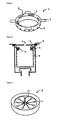
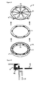
- Figure 1 shows a Slime Remover 1 of the present invention, that consists of ring-shaped Container Main Body 2 fitted to a shape of an inlet pipe or a garbage basket and four pieces of Holder 3 to sit Container Main Body 2 at the upper part of the inlet pipe or basket. It has two or more rectangular Drainage Flow-in Holes 4 in the mildly angled upper surface of Container Main Body 2, and two or more circular Solution Flow-out Holes 5 in the lower side of Container Main Body 2.
- Container Main Body 2 though not illustrated, is constructed so that the upper and lower main bodies can be vertically separated into two. The space between the upper and lower main bodies forms a storage capable of storing a solid containing a microorganism growth retarding substance (hereinafter referred to as "chemical").
- Figure 2 is a vertical cross-section when the above Slime Remover 1 with more than one small spherical piece of Chemical 6 is applied to Garbage Basket 9 under Rubber Filter 8 at Kitchen Sink Drain Outlet 7.
- Rubber Filter 8 usually has drainage flow-out holes, such as shown in Figure 3. When drainage is in a large volume, most of it flows out from Center 10 and drains down as it is. Some of it flow down through Circular Holes 11 provided in the peripheral portion. Some of the flowing drainage reaches the chemical storage through Drainage Flow-in Holes 4 and dissolves Chemical 6.
- the chemical-dissolved solution flows out from Solution Flow-out Holes 5 about when no more water drains down, flows down along the wall of Garbage Basket 9, and diffuses over the bottom surface on reaching the bottom so as to efficiently remove slime. In the case of insufficient slime removal on the bottom surface of Garbage Basket 9, it is possible to make a small number of solution flow-out holes in the bottom of the inner side of Container Main Body 2.
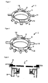
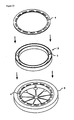
- FIG 4 shows a Slime Remover 1 of the same type as that shown in Figure 1.
- This Slime Remover 1 has Rim 12 to sit Container Main Body 2 at the upper part of an inlet pipe or garbage basket.
- Two or more Drainage Flow-in Holes 4 are circular in shape.
- More than one Solution Flow-out Hole 5 have a rectangular shape.
- a chemical to be stored can be of small spherical shape. Beads can also be used so as not to move around in the storage. In addition, it may be a ring-shaped one fitted to the shape of the storage container.
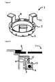
- a Slime Remover 1 of the present invention is composed of Container Main Body 2 with Chemical Storage 13 provided in part of the ring fitted to the shape of an inlet pipe or garbage basket and four pieces of Holder 3 to sit Container Main body 2 at the upper part of the inlet pipe or garbage basket.
- Drainage Flow-in Hole 4 consisting of more than one slit is provided in the upper surface of Container Main Body 2.
- Two or more circular Solution Flow-out Holes 5 are in the lower side of Container Main Body 2.
- the slit portion of Drainage Flow-in Hole 4 though not illustrated, is designed to be a lid for storing a chemical. From this hole, 1 to 3 pieces of relatively big Chemical 6, for example, cylindrical, can be inserted.
- Figure 6 shows a vertical cross-section when this Slime Remover 1 is applied to Garbage Basket 9 under Rubber Filter 8 at Kitchen Sink Drain Outlet 7.
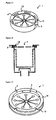
- FIGS 7 and 8 show Slime Removers 1 of the present invention that can apply to inlet pipes and garbage baskets of various diameters.
- These Slime Removers 1 are composed of Container Main Body 2 of shape of ring or the like that is smaller than the diameters of inlet pipes or garbage baskets, and, for example, 4 pieces of Holder Trough 14 that sit Container Main Body 2 at the upper part of an inlet pipe or garbage basket and work as drainage guiding troughs as well, and two or more Distribution Pipes 15 ( Figure 7) or Distribution Troughs 16 ( Figure 8) extending from two or more Solution Flow-out Holes 5 provided in the lower side of Container Main Body 2 and whose tips can touch the upper part of the drainpipe or garbage basket. There are two or more rectangular Drainage Flow-in Holes 4 in the bottom of the circumferential groove of the upper surface of Container Main Body 2.
- the above Holder Troughs 14 may have a U shape only in the upper surface for easy drainage guiding, as shown in Figure 7, or are flat plates as shown in Figure 8. For the convenience of applying to inlet pipes and garbage baskets of various diameters, it is preferable to make Holder Troughs 14 longer beforehand and to cut them to fit to the diameters.
- the said Distribution Pipes 15 and Troughs 16 are favorably made of flexible materials.
- Distribution Pipes 15 may be of bugle shape with the tip crushed or of a circular tube shape, as shown in Figure 7.
- Figure 9 shows a vertical cross-section of the key area, when this Slime Remover 1 is applied to Garbage Basket 9 under Rubber Filter 8 at Kitchen Sink Drain Outlet 7.
- Distribution Pipes 15 and Troughs 16 are used in a condition that their tips are located lower than the base, as shown in Figure 9.
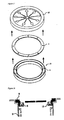
- FIG 13 shows a Slime Remover 1 of the present invention that has Chemical Storage 13 in the periphery of Rubber Filter 18 at Kitchen Sink Drain Outlet 7.
- This Slime Remover 1 has more than one rectangular Drainage Flow-in Hole 4 in the peripheral upper surface of Rubber Filter 18 and two or more circular Solution Flow-out Holes 5 in the peripheral bottom of Rubber Filter 18.
- Figure 14 shows a vertical cross-section when this Slime Remover 1 with Chemical Storage 13 provided in the periphery of Rubber Filter 18 and containing small granules of Chemical 6 is applied to Kitchen Sink Drain Outlet 7.
- a Slime Remover 1 of the present invention is shown that has Chemical Storage 13 in the side of the outer periphery of Rubber Filter 18 at Kitchen Sink Drain Outlet 7.
- This Slime Remover 1 is provided with more than one rectangular Drainage Flow-in Hole 4 in the outer peripheral edge of the upper surface of Rubber Filter 18, and with two or more circular Solution Flow-out Holes 5 in the bottom of the peripheral edge and inner side.
- Figure 16 shows a vertical cross-section when this Slime Remover 1, with more than one small granule of Chemical 6 filled in a water-permeable tube and set in the inside of Chemical Storage 13 provided in the outer peripheral side of Rubber Filter 18, is applied to Kitchen Sink Drain Outlet 7.
- the Slime Remover 1 consisting of this Rubber Filter 18 particularly has more than one circular Solution Flow-out Hole 5 in the inner peripheral side of Rubber Filter 18 so as to be able to prevent slime from generating, for example, on the front and back surfaces of radially cut Rubber Filter 18.
- Figure 17 shows a Slime Remover 1 of the present invention, with ring-shaped Chemical Storage 19 capable of fixing freely in the bottom of Rubber Filter 8 which is fixed to Rubber Filter 8 at Kitchen Sink Drain Outlet 7.
- the ring-shaped Chemical Storage 19 has more than one circular Drainage Flow-in Hole 4 in the upper lid, and more than one circular Solution Flow-out Hole 5 in the bottom of the storage main body.
- Figure 18 shows a vertical cross-section when a Slime Remover 1, with the ring-shaped Chemical Storage 19 containing small granules of Chemical 6 in the storage main body which is set and fixed to the bottom of Rubber Filter 8, is applied to Kitchen Sink Drain Outlet 7.
- Figure 19 shows another form of a slime remover of the present invention, with a ring-shaped chemical storage capable of fixing freely in the bottom of Rubber Filter 8 and fixed to Rubber Filter 8 at the drain outlet of a kitchen sink.
- Rubber Filter 8 has more than one rectangular Drainage Flow-in Hole 23 in the inner peripheral edge, more than one Solution Flow-out Hole 24 in the inner side, and more than one Holding Tab 25 to engage and fix the chemical storage to the bottom of the peripheral outer edge.
- the ring-shaped chemical storage is composed of a container lid and Container Main Body 19.
- the container lid has Drainage Flow-in Slits 4 along the direction to the center of the sink drain outlet (corresponding to the above rectangular Drainage Flow-in Holes 23).
- Container Main Body 19 is equipped with Drainage Flow-in Slits 4 (corresponding to the above rectangular Drainage Flow-in Holes 23) composing more than one slit aligned to the above Drainage Flow-in Slits 4 and Solution Flow-out Holes/Exhausts 26 (corresponding to the above Solution Flow-out Holes 24) in the inner upper side, more than one circular Solution Flow-out Hole 5 in the bottom, and more than one Locating Socket 27 (corresponding to the above Holding Tab 25) in the bottom of the outer peripheral edge.
- Drainage Flow-in Slits 4 corresponding to the above rectangular Drainage Flow-in Holes 23
- Solution Flow-out Holes/Exhausts 26 corresponding to the above Solution Flow-out Holes 24
- Locating Socket 27 corresponding to the above Holding Tab 25
- FIG. 20 is a rough vertical cross-section when the above slime remover, with a ring-shaped chemical storage storing small granules of Chemical 6 in the storage main body and engaged and fixed to the inside of the bottom of Rubber Filter 8, is applied to the drain outlet of a kitchen sink.
- Figure 21 shows a slime remover similar to that shown in Figure 19.
- Figure 22 is an enlarged view of part of it.
- a slime remover of this type has Rubber Filter 8 to which a ring-shaped chemical storage capable of fixing freely in the bottom of Rubber Filter 8 is fixed.
- Rubber Filter 8 has more than one rectangular Drainage Flow-in Hole in the inner peripheral edge, more than one Solution Flow-out Hole in the inner side, and 3 pieces of Holding Tab 25' to engage and fix the chemical storage in the bottom periphery of the inner side.
- the ring-shaped chemical storage of which the lid and main body of the container are firmly fixed together, has drainage flow-in slits composing more than one slit along the direction towards the center of the inlet pipe and locating in places from the upper surface to the upper part of the inner side, at the positions corresponding to the above rectangular drainage flow-in holes. It has also more than one circular Solution Flow-out Hole 5 in the inner side, more than one Solution Flow-out Hole/Exhaust 26 in the outer side, more than one circular Solution Flow-out Hole 5 in the bottom, and more than one Solution Flow-out Hole/Exhaust 26' in the outer side.
- Figure 23 shows a Slime Remover 1 of the present invention with ring-shaped Chemical Storage 19 capable of fixing freely in the inner upper side of Rubber Filter 8 and fixed to Rubber Filter 8 at Kitchen Sink Drain Outlet 7.
- the ring-shaped Chemical Storage 19 has more than one rectangular Drainage Flow-in Hole 4 in the upper surface of the filter, and more than one circular Solution Flow-out Hole 5 in the bottom of the storage main body.
- Chemical Storage 19, fixed to the inside of the upper part of Rubber Filter 8, lets a chemical-dissolved solution touch the front and back surfaces of Rubber Filter 8.
- Figure 24 is a vertical cross-section when this Slime Remover 1, with ring-shaped Chemical Storage 19 storing small granules of Chemical 6 in the storage main body and engaged and fixed to the inside of the upper part of Rubber Filter 8, is applied to Kitchen Sink Drain Outlet 7.
- FIG 25 shows a Slime Remover 1 of the present invention applicable to inlet pipes and garbage baskets of various diameters.
- This Slime Remover 1 consists of Container Main Body 2 of a ring shape as big as or smaller than the diameter of an inlet pipe or garbage basket, 4 pieces of Holder Trough 14 that sit Container Main Body 2 at the upper part of the inlet pipe or the basket and work as drainage guiding troughs as well, and more than one Pointed Distribution Fine Rod 20 made of plastic or the like, that are integrated in the vicinity of more than one circular Solution Flow-out Hole 5 in the bottom of Container Main Body 2 and whose tips can touch the upper part of a drainpipe or garbage basket.
- Drainage Flow-in Holes 4 there are two or more rectangular Drainage Flow-in Holes 4 in the bottom of the circumferential groove of the upper surface of Container Main Body 2.
- a chemical-dissolved solution from Solution Flow-out Holes 5 can reach the wall surface of the inlet pipe or garbage basket by traveling along Pointed Distribution Fine Rods 20, because of its slow flowing-out speed.
- Pointed Distribution Fine Rods 20 made of plastics or the like are flexible so as to be able to touch the wall surface, even if Container Main Body 2 is smaller than the diameters of inlet pipes or garbage baskets.
- Container Main Body 2 though not illustrated, is constructed so that the upper and lower main bodies can be vertically separated into two. The space between the upper and lower main bodies forms Chemical Storage 13 capable of storing Chemical 6.
- FIG. 26 shows a vertical cross-section of the key area when this Slim Remover 1 is applied to Garbage Basket 9 under Rubber Filter 8 at Kitchen Sink Drain Outlet 7. As shown in Figure 26, Pointed Distribution Fine Rods 20 are used in the condition that their tips are located lower than the base.
- FIG 27 shows a Slime Remover 1 of the present invention applicable to inlet pipes and garbage baskets where it is difficult to install Container Main Body 2 on their upper part.
- This Slime Remover 1 consists of Container Main Body 2 of ring shape or the like, and 3 pieces of inverted L-shaped Brackets 21 vertically fixed on Container Main Body 2 and for fixing Container Main Body 2 to the top of an inlet pipe or a garbage basket.
- Figure 28 shows a rough vertical cross-section of the key area when this Slime Remover 1 is applied to Garbage Basket 9 under Rubber Filter 8 at Kitchen Sink Drain Outlet 7.
- This Slime Remover 1 can be easily installed even if there are obstacles at an inlet pipe or at the upper part of a garbage basket, such as Basket Handle 22, while installing the remover. It is also possible to make Container Main Body 2 of Slime Remover 1 a little smaller than the diameter of an inlet pipe or a garbage basket and to provide the above Pointed Distribution Fine Rods 20 made of plastic or the like in the vicinity of Solution Flow-out Holes 5.
- the dispersibility of a chemical-dissolved solution was tested using a slime remover shown in Figure 3 (24 drainage flow-in holes of 4 mm in diameter, 12 solution flow-out holes of 2.4 mm x 1 mm, and 20 ml of water, the maximum volume the container can hold, flowing out in 20 seconds).
- a test chemical was prepared in the way that the following ingredients, which are pharmaceutical testing chemicals and are regarded to be stable in terms of color elution, were mixed to make tablets by a manual, oil-pressure tablet machine owned by the investors' institute in order to understand the dispersibility of the chemical solution.
- a commercially available container for storing a slime remover of chlorine type was hung by a string for the use as a comparative example.
- Example: 26 disc-type tablets of 11 mm in diameter are stored. (Chemical weight: 0.5g x 26 tablets 13g)
- Comparative Example 1 disc-type tablet of 30 mm in diameter is stored. (Chemical weight: 12g)
- Test conditions were that a kitchen sink made by Mikado Co., Ltd. with a large sink drain outlet was installed, a transparent PVC plate was applied so as to make drainage observation easy, the slime remover of the present invention or a dissolution container of Comparative Example for DICHLOTOP was set, a rubber filter was placed, and tap water flowed at a rate of about 6L/min. The dispersibility of the solutions containing color matter was observed in garbage baskets. It was found that, with the slime remover of the present invention, the chemical dispersed all over the garbage basket. With the remover of Comparative Example, the chemical partially touched only the bottom of the dissolution container, because of a string-hanging type.
- the slime remover of the present invention was installed in a household kitchen sink for 2 months for a monitoring test. It was confirmed that no garbage entered into the container, and slime was prevented from generating on the garbage filter, garbage basket, the inner surface of the drainpipe and the like, over the 2 months.
- TEP-CMI a clathrate compound prepared by the reaction between 2 moles of 5-chloro-2-methyl-4-isothiazolin-3-one as a guest antimicrobial agent and 1 mole of 1,1,2,2-tetrakis(4-hydroxyphenyl)ethane as a multi-molecular host compound
- acetoacetate-o-toluidide as a base material was placed in a continuous oil-pressure tablet machine with dies of 10 mm in diameter and tablets of 3g in weight were made under pressure of 1t/cm 2 .
- TEP-CMI refers to a clathrate compound prepared by the reaction between 2 moles of 5-chloro-2-methyl-4-isothiazolin-3-one as a guest antimicrobial agent and 1 mole of 1,1,2,2-tetrakis(4-hydroxyphenyl)ethane as a multi-molecular host compound
- Bronopol is an antimicrobial agent, 2-bromo-2-nitropropan-1,3-diol
- TIAA is 2,3,3-triiodoallyl alcohol
- HPC is a binder, hydroxypropyl cellulose.
- a continuous oil-pressure tablet machine with dies of 10 mm in diameter was installed and tablets were made under heavy pressure of 1t/cm 2 .
- a test for "tabletability" was carried out in regard to split, capping, glazability, adhesion and other properties. All the samples were rated as " ⁇ " in the tabletability evaluation. None of them were bad in tableting.
- a tablet of each of the molded samples was placed in a 200-ml plastic cup, and 200 ml of distilled water was added. It was left at room temperature for 24 hours to examine the disintegration of the molded. None of the samples were disintegrated.
- a tablet of a molded product was placed in a commercially available container for storing a slime removing agent.
- the container with the tablet was set by hanging with a string in water at the depth of 25 to 29 cm in a commercially available pipette cleaner of 18 cm in diameter and 58 cm deep (amount of cleaning water: 14.75L, temperature of cleaning water: 35 to 40°C, cleaning water contacting time: 3 minutes, and cleaning interval: 6.6 minutes/time). It was cleaned continuously and the dissolving rate was measured.
- the figures in Table 1 show times until the molded products were completely dissolved.
- clathrate disintegration (%) refers to an elution rate of the antimicrobial agent from the clathrate compound.
- the base materials used in the present invention let the clathrate compound disintegrate approximately as quickly as the blank sample did.
- Polyethylene oxide used for a comparison caused the disintegration of the clathrate compound at a higher rate. From the viewpoint of the clathrate disintegration rate, the base materials used in the present invention were found to be better.
- the drain slime removers of the present invention can be easily installed in the upper parts of inlet pipes and are excellent in safety and handling. From a container storing a slime preventing/removing agent, an agent-dissolved solution can spread over the wall surface of a drainpipe. Because the opening areas of both drainage flow-in holes and solution flow-out holes are adjusted, only a minimum amount of water required is taken in the inside of the container while drainage is flowing. A chemical-dissolved solution flows out from the container even after water has finished draining. When a conventional basket-type container is used, most of the chemical flows out together with drainage so that the agent can not stay long enough on the slime contaminated portion, having no effect on removing slime.
- the drain slime removers of the present invention a chemical-dissolved solution, which is not diluted with draining water, contacts slime contaminated portions for a long period of time. Therefore, a small amount of chemical efficiently prevents slime from generating, and an impact on the environment is small even if a chlorine-type chemical is used, thanks to a very small volume of chemical flowing out in drainage. Besides, the active ingredient dissolves at an appropriate rate, so that slime is not only removed but also prevented from generating for a long time, when a remover is installed in a place where slime is generated by metabolites of miscellaneous germs, mildews and the like, such as the drain outlets of kitchen sinks and bathrooms.
- the slime preventing/removing agents of the present invention have none of the problems of chlorine smell and corrosion, are excellent in safety and handling, and make it possible to let active ingredients dissolve stably.
Landscapes
- Life Sciences & Earth Sciences (AREA)
- Engineering & Computer Science (AREA)
- Health & Medical Sciences (AREA)
- General Health & Medical Sciences (AREA)
- Plant Pathology (AREA)
- Agronomy & Crop Science (AREA)
- Environmental Sciences (AREA)
- Dentistry (AREA)
- Wood Science & Technology (AREA)
- Zoology (AREA)
- Hydrology & Water Resources (AREA)
- Water Supply & Treatment (AREA)
- Pest Control & Pesticides (AREA)
- Environmental & Geological Engineering (AREA)
- Public Health (AREA)
- Chemical & Material Sciences (AREA)
- Organic Chemistry (AREA)
- Toxicology (AREA)
- Agricultural Chemicals And Associated Chemicals (AREA)
- Detergent Compositions (AREA)
- Sink And Installation For Waste Water (AREA)
- Treatment Of Sludge (AREA)
- Housing For Livestock And Birds (AREA)
Applications Claiming Priority (5)
| Application Number | Priority Date | Filing Date | Title |
|---|---|---|---|
| JP24680798 | 1998-09-01 | ||
| JP25139298 | 1998-09-04 | ||
| JP05425399A JP3578655B2 (ja) | 1998-03-03 | 1999-03-02 | 排水口用ヌメリ取り器 |
| JP7368899 | 1999-03-18 | ||
| EP99940598A EP1113112B1 (fr) | 1998-09-01 | 1999-09-01 | Separateur de boues et agent de prevention et d'elimination des boues |
Related Parent Applications (2)
| Application Number | Title | Priority Date | Filing Date |
|---|---|---|---|
| EP99940598.8 Division | 1999-09-01 | ||
| EP99940598A Division EP1113112B1 (fr) | 1998-09-01 | 1999-09-01 | Separateur de boues et agent de prevention et d'elimination des boues |
Publications (3)
| Publication Number | Publication Date |
|---|---|
| EP1676478A2 true EP1676478A2 (fr) | 2006-07-05 |
| EP1676478A3 EP1676478A3 (fr) | 2006-07-12 |
| EP1676478B1 EP1676478B1 (fr) | 2011-08-24 |
Family
ID=27463031
Family Applications (2)
| Application Number | Title | Priority Date | Filing Date |
|---|---|---|---|
| EP99940598A Expired - Lifetime EP1113112B1 (fr) | 1998-09-01 | 1999-09-01 | Separateur de boues et agent de prevention et d'elimination des boues |
| EP06111370A Expired - Lifetime EP1676478B1 (fr) | 1998-09-01 | 1999-09-01 | Séparateur de boues et agent de prévention et d'élimination des boues |
Family Applications Before (1)
| Application Number | Title | Priority Date | Filing Date |
|---|---|---|---|
| EP99940598A Expired - Lifetime EP1113112B1 (fr) | 1998-09-01 | 1999-09-01 | Separateur de boues et agent de prevention et d'elimination des boues |
Country Status (5)
| Country | Link |
|---|---|
| US (3) | US6528467B1 (fr) |
| EP (2) | EP1113112B1 (fr) |
| AT (1) | ATE499324T1 (fr) |
| DE (1) | DE69943218D1 (fr) |
| WO (1) | WO2000012828A1 (fr) |
Cited By (1)
| Publication number | Priority date | Publication date | Assignee | Title |
|---|---|---|---|---|
| WO2000012828A1 (fr) | 1998-09-01 | 2000-03-09 | Nippon Soda Co., Ltd. | Separateur de boues et agent de prevention et d'elimination des boues |
Families Citing this family (40)
| Publication number | Priority date | Publication date | Assignee | Title |
|---|---|---|---|---|
| FR2837224B1 (fr) * | 2002-03-18 | 2004-07-02 | Eric Vincent | Bonde traitante |
| MXPA06004514A (es) | 2003-10-24 | 2006-07-06 | Novapharm Res Australia | Tableta para bandeja de goteo. |
| US7737309B2 (en) * | 2004-07-13 | 2010-06-15 | Nippon Soda Co., Ltd. | Clathrate compound, method for controlling concentration of aqueous agricultural chemical active ingredient solution, and agricultural chemical formulation |
| US7887697B2 (en) * | 2006-05-10 | 2011-02-15 | Mark Mangrom | Aromatic drain device |
| US20080114455A1 (en) * | 2006-11-15 | 2008-05-15 | Warsaw Orthopedic, Inc. | Rotating Interspinous Process Devices and Methods of Use |
| AR064778A1 (es) | 2007-01-12 | 2009-04-22 | Albemarle Corp | Biocidas a base de bromo adecuados para el procesamiento de alimentos |
| US9629376B2 (en) | 2007-01-12 | 2017-04-25 | Albemarle Corporation | Microbiocidal treatment of edible fruits and vegetables |
| USD686306S1 (en) * | 2007-03-20 | 2013-07-16 | Neoperl Gmbh | Swivel adapter for faucets |
| US7610635B2 (en) * | 2007-05-09 | 2009-11-03 | S.C. Johnson & Son, Inc. | Drain cleaner |
| US8007707B1 (en) * | 2007-05-15 | 2011-08-30 | Fresh Products, Inc. | Method of manufacture air freshening article |
| GB2453940A (en) * | 2007-10-23 | 2009-04-29 | Moshe Buhbut | Device for adding cleansing material to a cistern |
| US9157053B1 (en) | 2009-07-01 | 2015-10-13 | Thomas Tupaj | Laundry washing machine deodorizer |
| USD654152S1 (en) * | 2010-12-11 | 2012-02-14 | Victor Schulz | Garbage disposal blade guard |
| US8409433B2 (en) | 2011-04-20 | 2013-04-02 | Aromatic Drain Device, Inc. | Device for use with floor drains |
| KR101746898B1 (ko) * | 2011-07-12 | 2017-06-14 | 닛뽕소다 가부시키가이샤 | 변형 정제상 점액 제거제 |
| JPWO2013011643A1 (ja) * | 2011-07-18 | 2015-02-23 | 株式会社大和 | マット |
| US9243394B2 (en) | 2011-09-20 | 2016-01-26 | Fresh Products, Inc. | Replaceable restroom urinal assemblies, including urinal screens |
| US20140033416A1 (en) * | 2012-05-23 | 2014-02-06 | Cary Cohen | Sink Drain Conditioning Systems and Methods |
| USD669969S1 (en) | 2012-06-19 | 2012-10-30 | Paul Bradley Forrest | Drain insert |
| USD682994S1 (en) | 2012-08-16 | 2013-05-21 | Victor Schulz | Garbage disposal blade guard |
| US20140201904A1 (en) * | 2013-01-22 | 2014-07-24 | Michael A. Sapara, Jr. | Insect-discouraging drain device |
| USD724188S1 (en) * | 2013-04-29 | 2015-03-10 | Saint-Gobain Performance Plastics Corporation | Hose support |
| USD724189S1 (en) * | 2013-04-29 | 2015-03-10 | Saint-Gobain Performance Plastics Corporation | Hose support |
| USD725240S1 (en) * | 2013-04-29 | 2015-03-24 | Saint-Gobain Performance Plastics Corporation | Hose support |
| USD724705S1 (en) * | 2013-04-29 | 2015-03-17 | Saint-Gobain Performance Plastics Corporation | Hose support |
| US20150218786A1 (en) * | 2014-01-08 | 2015-08-06 | Saundra Sue CULLEN | Sink insert with cleaning surface |
| US9493933B2 (en) * | 2014-08-07 | 2016-11-15 | Brasscraft Manufacturing Company | Pedestal strainer for a sink drain |
| US10058542B1 (en) | 2014-09-12 | 2018-08-28 | Thioredoxin Systems Ab | Composition comprising selenazol or thiazolone derivatives and silver and method of treatment therewith |
| USD778411S1 (en) | 2014-11-05 | 2017-02-07 | Fresh Products, Inc. | Urinal screen |
| DE202015102279U1 (de) | 2014-11-05 | 2015-08-14 | Fresh Products, Inc. | Urinalsieb |
| USD778412S1 (en) | 2014-11-10 | 2017-02-07 | Fresh Products, Inc. | Urinal screen |
| USD849209S1 (en) * | 2016-11-08 | 2019-05-21 | Blackhawk Tool & Machine, LLC | Chemistry delivery device |
| AU2018388576A1 (en) | 2017-12-20 | 2020-07-23 | Fresh Products, Inc. | Urinal screens |
| US11175068B1 (en) | 2018-01-30 | 2021-11-16 | Brian Desilets | Air conditioning drain line system |
| US10895422B1 (en) | 2018-01-30 | 2021-01-19 | Brian Desilets | Chemical delivery system for AC drain line |
| USD925009S1 (en) | 2018-10-25 | 2021-07-13 | Fresh Products, Inc. | Urinal screen |
| CN110561767B (zh) * | 2019-09-17 | 2021-08-17 | 河北沃福科技有限公司 | 一种扣压机控制系统及扣压机 |
| US10982425B1 (en) * | 2019-10-01 | 2021-04-20 | NeverClog LLC | Apparatus for capturing and destroying hair within a shower drain |
| US12163326B1 (en) * | 2019-10-01 | 2024-12-10 | NeverClog, LLC | System for capturing and destroying hair or waste within a commercial shower drain |
| USD1078945S1 (en) | 2022-07-13 | 2025-06-10 | Fresh Products, Inc. | Urinal screen |
Citations (19)
| Publication number | Priority date | Publication date | Assignee | Title |
|---|---|---|---|---|
| JPH0646069A (ja) | 1992-07-27 | 1994-02-18 | Hitachi Ltd | ループバックテスト装置 |
| JPH07184823A (ja) | 1993-12-27 | 1995-07-25 | Suzuki Yushi Kogyo Kk | 家庭用ヌメリ取り具 |
| EP0684415A1 (fr) | 1994-05-24 | 1995-11-29 | Hubert Bösch | Mécanisme de commande pour une soupape à vide |
| JPH08113502A (ja) | 1994-08-26 | 1996-05-07 | Nippon Soda Co Ltd | 早溶性成形物 |
| JPH08128090A (ja) | 1994-11-01 | 1996-05-21 | Ueki:Kk | 洗浄剤入り洗浄具及びこれに用いてなる洗浄容器 |
| JPH08158441A (ja) | 1994-12-01 | 1996-06-18 | Yamaha Living Tec Kk | 生ゴミ投入用網籠 |
| JPH08157305A (ja) | 1994-11-29 | 1996-06-18 | Hiroaki Endo | 除菌剤 |
| JPH08268818A (ja) | 1995-04-03 | 1996-10-15 | Shiraishi Chuo Kenkyusho:Kk | ぬめり取り剤組成物及びぬめり取り剤の製造方法 |
| JPH09292A (ja) | 1995-06-20 | 1997-01-07 | Kawasaki Steel Corp | グルタチオン含有藻体およびグルタチオンの製造方法 |
| JPH0930915A (ja) | 1995-07-18 | 1997-02-04 | Hagiwara Giken:Kk | 抗菌性組成物 |
| JPH0931495A (ja) | 1995-07-13 | 1997-02-04 | Meiji Yakuhin Kogyo Kk | シンクバスケット用浄化剤とその製造方法 |
| JPH0950384A (ja) | 1995-08-09 | 1997-02-18 | Mitsubishi Electric Corp | マイクロコンピュータ |
| JPH09124422A (ja) | 1995-10-31 | 1997-05-13 | Daito Kagaku Kk | ぬめり防止及び除菌用薬剤 |
| JPH09124423A (ja) | 1995-11-07 | 1997-05-13 | Nippo Kagaku Kk | 環境殺菌剤組成物の製造方法 |
| JPH09154923A (ja) | 1995-12-06 | 1997-06-17 | Matsushita Electric Ind Co Ltd | 防菌防黴装置 |
| JPH09194313A (ja) | 1996-01-22 | 1997-07-29 | Hiroaki Endo | 流水性除菌剤 |
| JPH09206040A (ja) | 1996-01-30 | 1997-08-12 | Kagome Co Ltd | リンゴジュースの製造方法 |
| JPH09227317A (ja) | 1996-02-19 | 1997-09-02 | Nippo Kagaku Kk | 環境殺菌剤及び流し台用ぬめり防止具 |
| EP1113112A1 (fr) | 1998-09-01 | 2001-07-04 | Nippon Soda Co., Ltd. | Separateur de boues et agent de prevention et d'elimination des boues |
Family Cites Families (29)
| Publication number | Priority date | Publication date | Assignee | Title |
|---|---|---|---|---|
| US852044A (en) | 1906-04-17 | 1907-04-30 | William B Van Der Minden | Sieve for sinks and the like. |
| US1916357A (en) | 1931-05-15 | 1933-07-04 | Henry J Brownstein | Deodorant holder |
| US2087592A (en) * | 1935-11-25 | 1937-07-20 | William J Chesnut | Detergent cartridge for waste pipes |
| US2723905A (en) * | 1952-11-24 | 1955-11-15 | Gerald N Coakley | Drain pipe solvent dispenser |
| US3112499A (en) | 1960-05-12 | 1963-12-03 | E C K Mfg Company Ltd | Means for disinfecting and/or deodorizing waste pipes |
| US3597772A (en) * | 1968-12-13 | 1971-08-10 | Chemtrust Ind Corp | Lavatory sanitation bodies |
| JPS6153201A (ja) * | 1984-08-21 | 1986-03-17 | Kurita Water Ind Ltd | 包接化合物 |
| JPS62142147A (ja) * | 1985-12-17 | 1987-06-25 | Kurita Water Ind Ltd | ジフェン酸ビス(ジシクロヘキシルアミド)及びそれを用いた徐放性抗菌剤 |
| JPS62175401A (ja) * | 1986-01-28 | 1987-08-01 | Kurita Water Ind Ltd | 包接化合物 |
| JPS6440408A (en) * | 1987-08-06 | 1989-02-10 | Dai Ichi Kogyo Seiyaku Co Ltd | Germicidal tablet composition |
| JPH01190601A (ja) * | 1988-01-25 | 1989-07-31 | Kurita Water Ind Ltd | 包接化合物の製造方法 |
| US4911859A (en) * | 1988-09-15 | 1990-03-27 | Kiwi Brands, Inc. | Toilet bowl cleaners containing iodophors |
| JPH02142709A (ja) * | 1988-11-24 | 1990-05-31 | Kurita Water Ind Ltd | 有害生物防除剤 |
| US5165119A (en) * | 1990-07-06 | 1992-11-24 | Amenity Co., Ltd. | Chemical setting receptacle for urinal scupper or the like |
| FR2665158B1 (fr) * | 1990-07-30 | 1993-12-24 | Air Liquide | Clathrates de peroxyacides. |
| JP2985604B2 (ja) * | 1993-10-01 | 1999-12-06 | 栗田工業株式会社 | 包接化合物 |
| JPH07148498A (ja) | 1993-11-26 | 1995-06-13 | Nippon Soda Co Ltd | 水洗式実験動物飼育用架台の尿石防止剤及び尿石防止方法 |
| JP3292590B2 (ja) | 1994-05-10 | 2002-06-17 | 株式会社工生研 | 清浄剤 |
| JPH0853304A (ja) | 1994-05-18 | 1996-02-27 | Nippon Soda Co Ltd | 包接化合物の成形物 |
| JPH08151310A (ja) | 1994-11-29 | 1996-06-11 | Nippon Shokubai Co Ltd | 抗菌性重合体およびこれを含有する抗菌剤 |
| JPH08151303A (ja) | 1994-11-29 | 1996-06-11 | Somar Corp | 工業用殺菌剤組成物 |
| US5614206A (en) * | 1995-03-07 | 1997-03-25 | Wright Medical Technology, Inc. | Controlled dissolution pellet containing calcium sulfate |
| JPH08270037A (ja) | 1995-03-31 | 1996-10-15 | Matsushita Electric Ind Co Ltd | 水切り袋 |
| US5637308A (en) | 1995-07-10 | 1997-06-10 | Buckman Laboratories International, Inc. | Tabletized ionene polymers |
| CZ7798A3 (cs) * | 1995-07-10 | 1998-06-17 | Buckman Laboratories International, Inc. | Tableta s ionenovým polymerem |
| JPH09296492A (ja) | 1996-05-08 | 1997-11-18 | Sekisui Chem Co Ltd | 排水口用ごみ取り具 |
| JPH10245308A (ja) * | 1997-03-05 | 1998-09-14 | Nippon Soda Co Ltd | 非さらし粉系ヌメリ防除剤 |
| JPH10245306A (ja) | 1997-03-05 | 1998-09-14 | Nippon Soda Co Ltd | 有機ヨード系ヌメリ防除剤 |
| JPH1143404A (ja) | 1997-07-29 | 1999-02-16 | Enkuraa Business:Kk | 除菌清浄剤 |
-
1999
- 1999-09-01 WO PCT/JP1999/004732 patent/WO2000012828A1/fr not_active Ceased
- 1999-09-01 DE DE69943218T patent/DE69943218D1/de not_active Expired - Lifetime
- 1999-09-01 EP EP99940598A patent/EP1113112B1/fr not_active Expired - Lifetime
- 1999-09-01 AT AT99940598T patent/ATE499324T1/de not_active IP Right Cessation
- 1999-09-01 US US09/763,538 patent/US6528467B1/en not_active Expired - Lifetime
- 1999-09-01 EP EP06111370A patent/EP1676478B1/fr not_active Expired - Lifetime
-
2002
- 2002-09-20 US US10/252,150 patent/US6927199B2/en not_active Expired - Lifetime
-
2004
- 2004-12-27 US US11/022,724 patent/US7098174B2/en not_active Expired - Fee Related
Patent Citations (19)
| Publication number | Priority date | Publication date | Assignee | Title |
|---|---|---|---|---|
| JPH0646069A (ja) | 1992-07-27 | 1994-02-18 | Hitachi Ltd | ループバックテスト装置 |
| JPH07184823A (ja) | 1993-12-27 | 1995-07-25 | Suzuki Yushi Kogyo Kk | 家庭用ヌメリ取り具 |
| EP0684415A1 (fr) | 1994-05-24 | 1995-11-29 | Hubert Bösch | Mécanisme de commande pour une soupape à vide |
| JPH08113502A (ja) | 1994-08-26 | 1996-05-07 | Nippon Soda Co Ltd | 早溶性成形物 |
| JPH08128090A (ja) | 1994-11-01 | 1996-05-21 | Ueki:Kk | 洗浄剤入り洗浄具及びこれに用いてなる洗浄容器 |
| JPH08157305A (ja) | 1994-11-29 | 1996-06-18 | Hiroaki Endo | 除菌剤 |
| JPH08158441A (ja) | 1994-12-01 | 1996-06-18 | Yamaha Living Tec Kk | 生ゴミ投入用網籠 |
| JPH08268818A (ja) | 1995-04-03 | 1996-10-15 | Shiraishi Chuo Kenkyusho:Kk | ぬめり取り剤組成物及びぬめり取り剤の製造方法 |
| JPH09292A (ja) | 1995-06-20 | 1997-01-07 | Kawasaki Steel Corp | グルタチオン含有藻体およびグルタチオンの製造方法 |
| JPH0931495A (ja) | 1995-07-13 | 1997-02-04 | Meiji Yakuhin Kogyo Kk | シンクバスケット用浄化剤とその製造方法 |
| JPH0930915A (ja) | 1995-07-18 | 1997-02-04 | Hagiwara Giken:Kk | 抗菌性組成物 |
| JPH0950384A (ja) | 1995-08-09 | 1997-02-18 | Mitsubishi Electric Corp | マイクロコンピュータ |
| JPH09124422A (ja) | 1995-10-31 | 1997-05-13 | Daito Kagaku Kk | ぬめり防止及び除菌用薬剤 |
| JPH09124423A (ja) | 1995-11-07 | 1997-05-13 | Nippo Kagaku Kk | 環境殺菌剤組成物の製造方法 |
| JPH09154923A (ja) | 1995-12-06 | 1997-06-17 | Matsushita Electric Ind Co Ltd | 防菌防黴装置 |
| JPH09194313A (ja) | 1996-01-22 | 1997-07-29 | Hiroaki Endo | 流水性除菌剤 |
| JPH09206040A (ja) | 1996-01-30 | 1997-08-12 | Kagome Co Ltd | リンゴジュースの製造方法 |
| JPH09227317A (ja) | 1996-02-19 | 1997-09-02 | Nippo Kagaku Kk | 環境殺菌剤及び流し台用ぬめり防止具 |
| EP1113112A1 (fr) | 1998-09-01 | 2001-07-04 | Nippon Soda Co., Ltd. | Separateur de boues et agent de prevention et d'elimination des boues |
Cited By (1)
| Publication number | Priority date | Publication date | Assignee | Title |
|---|---|---|---|---|
| WO2000012828A1 (fr) | 1998-09-01 | 2000-03-09 | Nippon Soda Co., Ltd. | Separateur de boues et agent de prevention et d'elimination des boues |
Also Published As
| Publication number | Publication date |
|---|---|
| US20030032569A1 (en) | 2003-02-13 |
| EP1676478B1 (fr) | 2011-08-24 |
| ATE499324T1 (de) | 2011-03-15 |
| EP1113112A4 (fr) | 2005-09-14 |
| WO2000012828A1 (fr) | 2000-03-09 |
| US7098174B2 (en) | 2006-08-29 |
| EP1676478A3 (fr) | 2006-07-12 |
| US6528467B1 (en) | 2003-03-04 |
| US6927199B2 (en) | 2005-08-09 |
| US20050103709A1 (en) | 2005-05-19 |
| EP1113112A1 (fr) | 2001-07-04 |
| EP1113112B1 (fr) | 2011-02-23 |
| DE69943218D1 (de) | 2011-04-07 |
Similar Documents
| Publication | Publication Date | Title |
|---|---|---|
| US7098174B2 (en) | Slime remover and slime preventing/removing agent | |
| JP4612297B2 (ja) | 排水口用ヌメリ取り器 | |
| JP4647741B2 (ja) | 排水口用ヌメリ取り具 | |
| JP3578695B2 (ja) | 排水口用ヌメリ取り器 | |
| JP3421282B2 (ja) | 排水口用ヌメリ取り器 | |
| JP3630397B2 (ja) | ヌメリ防除剤 | |
| KR101746898B1 (ko) | 변형 정제상 점액 제거제 | |
| HK1038384A (en) | Slime remover and slime preventing/removing agent | |
| JP3958632B2 (ja) | 拡散型浴室排水口用ヌメリ取り器 | |
| JP2002266401A (ja) | 排水口用ゴミ取り具 | |
| JP5384561B2 (ja) | ヌメリ防除剤 | |
| JP2003041293A (ja) | 排水口用ヌメリ取り剤及びヌメリ取り具 | |
| JP2005048355A (ja) | ヌメリ防除機能付き洗面台用排水栓 | |
| JP2003013095A (ja) | 水流失性除菌洗浄剤 | |
| JP2001065020A (ja) | ヌメリ取り具 | |
| JP3421237B2 (ja) | ヌメリ取り具 | |
| JP2004324314A (ja) | 洗面台用ヌメリ取り器 | |
| JP2004100389A (ja) | 目皿一体固定型浴室排水口用ヌメリ取り器。 | |
| JP2003213755A (ja) | 目皿一体型浴室排水口用ヌメリ取り器 | |
| JPH1143404A (ja) | 除菌清浄剤 | |
| JP2005061098A (ja) | 洗面台用ヌメリ取り具 | |
| JP2004150106A (ja) | 装着型浴室排水口用ヌメリ取り器 | |
| WO2019155993A1 (fr) | Moyens d'élimination des boues | |
| ES2369376T3 (es) | Eliminador de cieno y agente de prevención/eliminación de cieno. | |
| ES2358974T3 (es) | Dispositivo de eliminación de lodo y agente de prevención/eliminación de lodo. |
Legal Events
| Date | Code | Title | Description |
|---|---|---|---|
| PUAI | Public reference made under article 153(3) epc to a published international application that has entered the european phase |
Free format text: ORIGINAL CODE: 0009012 |
|
| PUAL | Search report despatched |
Free format text: ORIGINAL CODE: 0009013 |
|
| AC | Divisional application: reference to earlier application |
Ref document number: 1113112 Country of ref document: EP Kind code of ref document: P |
|
| AK | Designated contracting states |
Kind code of ref document: A2 Designated state(s): AT BE CH CY DE DK ES FI FR GB GR IE IT LI LU MC NL PT SE |
|
| AK | Designated contracting states |
Kind code of ref document: A3 Designated state(s): AT BE CH CY DE DK ES FI FR GB GR IE IT LI LU MC NL PT SE |
|
| 17P | Request for examination filed |
Effective date: 20061216 |
|
| 17Q | First examination report despatched |
Effective date: 20070117 |
|
| AKX | Designation fees paid |
Designated state(s): AT BE CH CY DE DK ES FI FR GB GR IE IT LI LU MC NL PT SE |
|
| GRAP | Despatch of communication of intention to grant a patent |
Free format text: ORIGINAL CODE: EPIDOSNIGR1 |
|
| GRAS | Grant fee paid |
Free format text: ORIGINAL CODE: EPIDOSNIGR3 |
|
| GRAA | (expected) grant |
Free format text: ORIGINAL CODE: 0009210 |
|
| AC | Divisional application: reference to earlier application |
Ref document number: 1113112 Country of ref document: EP Kind code of ref document: P |
|
| AK | Designated contracting states |
Kind code of ref document: B1 Designated state(s): AT BE CH CY DE DK ES FI FR GB GR IE IT LI LU MC NL PT SE |
|
| REG | Reference to a national code |
Ref country code: GB Ref legal event code: FG4D |
|
| REG | Reference to a national code |
Ref country code: CH Ref legal event code: EP Ref country code: CH Ref legal event code: NV Representative=s name: MICHELI & CIE SA |
|
| REG | Reference to a national code |
Ref country code: IE Ref legal event code: FG4D |
|
| REG | Reference to a national code |
Ref country code: DE Ref legal event code: R096 Ref document number: 69943679 Country of ref document: DE Effective date: 20111020 |
|
| REG | Reference to a national code |
Ref country code: ES Ref legal event code: FG2A Ref document number: 2369376 Country of ref document: ES Kind code of ref document: T3 Effective date: 20111130 |
|
| REG | Reference to a national code |
Ref country code: NL Ref legal event code: VDEP Effective date: 20110824 |
|
| PG25 | Lapsed in a contracting state [announced via postgrant information from national office to epo] |
Ref country code: NL Free format text: LAPSE BECAUSE OF FAILURE TO SUBMIT A TRANSLATION OF THE DESCRIPTION OR TO PAY THE FEE WITHIN THE PRESCRIBED TIME-LIMIT Effective date: 20110824 Ref country code: PT Free format text: LAPSE BECAUSE OF FAILURE TO SUBMIT A TRANSLATION OF THE DESCRIPTION OR TO PAY THE FEE WITHIN THE PRESCRIBED TIME-LIMIT Effective date: 20111226 Ref country code: SE Free format text: LAPSE BECAUSE OF FAILURE TO SUBMIT A TRANSLATION OF THE DESCRIPTION OR TO PAY THE FEE WITHIN THE PRESCRIBED TIME-LIMIT Effective date: 20110824 Ref country code: FI Free format text: LAPSE BECAUSE OF FAILURE TO SUBMIT A TRANSLATION OF THE DESCRIPTION OR TO PAY THE FEE WITHIN THE PRESCRIBED TIME-LIMIT Effective date: 20110824 |
|
| REG | Reference to a national code |
Ref country code: AT Ref legal event code: MK05 Ref document number: 521235 Country of ref document: AT Kind code of ref document: T Effective date: 20110824 |
|
| PG25 | Lapsed in a contracting state [announced via postgrant information from national office to epo] |
Ref country code: CY Free format text: LAPSE BECAUSE OF FAILURE TO SUBMIT A TRANSLATION OF THE DESCRIPTION OR TO PAY THE FEE WITHIN THE PRESCRIBED TIME-LIMIT Effective date: 20110824 Ref country code: AT Free format text: LAPSE BECAUSE OF FAILURE TO SUBMIT A TRANSLATION OF THE DESCRIPTION OR TO PAY THE FEE WITHIN THE PRESCRIBED TIME-LIMIT Effective date: 20110824 Ref country code: GR Free format text: LAPSE BECAUSE OF FAILURE TO SUBMIT A TRANSLATION OF THE DESCRIPTION OR TO PAY THE FEE WITHIN THE PRESCRIBED TIME-LIMIT Effective date: 20111125 |
|
| PG25 | Lapsed in a contracting state [announced via postgrant information from national office to epo] |
Ref country code: BE Free format text: LAPSE BECAUSE OF FAILURE TO SUBMIT A TRANSLATION OF THE DESCRIPTION OR TO PAY THE FEE WITHIN THE PRESCRIBED TIME-LIMIT Effective date: 20110824 |
|
| PG25 | Lapsed in a contracting state [announced via postgrant information from national office to epo] |
Ref country code: MC Free format text: LAPSE BECAUSE OF NON-PAYMENT OF DUE FEES Effective date: 20110930 |
|
| REG | Reference to a national code |
Ref country code: IE Ref legal event code: MM4A |
|
| PG25 | Lapsed in a contracting state [announced via postgrant information from national office to epo] |
Ref country code: DK Free format text: LAPSE BECAUSE OF FAILURE TO SUBMIT A TRANSLATION OF THE DESCRIPTION OR TO PAY THE FEE WITHIN THE PRESCRIBED TIME-LIMIT Effective date: 20110824 |
|
| PLBE | No opposition filed within time limit |
Free format text: ORIGINAL CODE: 0009261 |
|
| STAA | Information on the status of an ep patent application or granted ep patent |
Free format text: STATUS: NO OPPOSITION FILED WITHIN TIME LIMIT |
|
| PG25 | Lapsed in a contracting state [announced via postgrant information from national office to epo] |
Ref country code: IE Free format text: LAPSE BECAUSE OF NON-PAYMENT OF DUE FEES Effective date: 20110901 |
|
| 26N | No opposition filed |
Effective date: 20120525 |
|
| REG | Reference to a national code |
Ref country code: DE Ref legal event code: R097 Ref document number: 69943679 Country of ref document: DE Effective date: 20120525 |
|
| PG25 | Lapsed in a contracting state [announced via postgrant information from national office to epo] |
Ref country code: LU Free format text: LAPSE BECAUSE OF NON-PAYMENT OF DUE FEES Effective date: 20110901 |
|
| REG | Reference to a national code |
Ref country code: FR Ref legal event code: PLFP Year of fee payment: 17 |
|
| REG | Reference to a national code |
Ref country code: FR Ref legal event code: PLFP Year of fee payment: 18 |
|
| PGFP | Annual fee paid to national office [announced via postgrant information from national office to epo] |
Ref country code: GB Payment date: 20160920 Year of fee payment: 18 Ref country code: CH Payment date: 20160920 Year of fee payment: 18 Ref country code: DE Payment date: 20160921 Year of fee payment: 18 |
|
| PGFP | Annual fee paid to national office [announced via postgrant information from national office to epo] |
Ref country code: FR Payment date: 20160921 Year of fee payment: 18 |
|
| PGFP | Annual fee paid to national office [announced via postgrant information from national office to epo] |
Ref country code: ES Payment date: 20160916 Year of fee payment: 18 |
|
| PGFP | Annual fee paid to national office [announced via postgrant information from national office to epo] |
Ref country code: IT Payment date: 20160922 Year of fee payment: 18 |
|
| REG | Reference to a national code |
Ref country code: DE Ref legal event code: R119 Ref document number: 69943679 Country of ref document: DE |
|
| REG | Reference to a national code |
Ref country code: CH Ref legal event code: PL |
|
| GBPC | Gb: european patent ceased through non-payment of renewal fee |
Effective date: 20170901 |
|
| REG | Reference to a national code |
Ref country code: FR Ref legal event code: ST Effective date: 20180531 |
|
| PG25 | Lapsed in a contracting state [announced via postgrant information from national office to epo] |
Ref country code: LI Free format text: LAPSE BECAUSE OF NON-PAYMENT OF DUE FEES Effective date: 20170930 Ref country code: DE Free format text: LAPSE BECAUSE OF NON-PAYMENT OF DUE FEES Effective date: 20180404 Ref country code: GB Free format text: LAPSE BECAUSE OF NON-PAYMENT OF DUE FEES Effective date: 20170901 Ref country code: CH Free format text: LAPSE BECAUSE OF NON-PAYMENT OF DUE FEES Effective date: 20170930 |
|
| PG25 | Lapsed in a contracting state [announced via postgrant information from national office to epo] |
Ref country code: IT Free format text: LAPSE BECAUSE OF NON-PAYMENT OF DUE FEES Effective date: 20170901 Ref country code: FR Free format text: LAPSE BECAUSE OF NON-PAYMENT OF DUE FEES Effective date: 20171002 |
|
| REG | Reference to a national code |
Ref country code: ES Ref legal event code: FD2A Effective date: 20181024 |
|
| PG25 | Lapsed in a contracting state [announced via postgrant information from national office to epo] |
Ref country code: ES Free format text: LAPSE BECAUSE OF NON-PAYMENT OF DUE FEES Effective date: 20170902 |